JP2016176449A - Compressor - Google Patents
Compressor Download PDFInfo
- Publication number
- JP2016176449A JP2016176449A JP2015058904A JP2015058904A JP2016176449A JP 2016176449 A JP2016176449 A JP 2016176449A JP 2015058904 A JP2015058904 A JP 2015058904A JP 2015058904 A JP2015058904 A JP 2015058904A JP 2016176449 A JP2016176449 A JP 2016176449A
- Authority
- JP
- Japan
- Prior art keywords
- working fluid
- discharge
- discharge port
- channel
- compressor
- Prior art date
- Legal status (The legal status is an assumption and is not a legal conclusion. Google has not performed a legal analysis and makes no representation as to the accuracy of the status listed.)
- Pending
Links
Images

Abstract
Description
本発明は、冷媒を圧縮する圧縮機に関する。 The present invention relates to a compressor that compresses a refrigerant.
本技術分野の背景技術として、台板に渦巻状のラップを立設した固定スクロールと、鏡板に渦巻状のラップを立設し固定スクロールと噛み合わされて圧縮室を形成する旋回スクロールと、圧縮室で圧縮した作動流体が吐出される吐出空間と、旋回スクロールまたは固定スクロールの少なくともいずれか一方の背面に設けられ旋回スクロールと固定スクロールの両部材の少なくとも一方を他方に押付けるための背圧室とを備えたスクロール圧縮機が知られている。
As background art of this technical field, a fixed scroll with a spiral wrap standing on a base plate, a swirl scroll that stands with a spiral wrap on a mirror plate and meshes with the fixed scroll to form a compression chamber, and a compression chamber A discharge space in which the working fluid compressed in
また、特許文献1には、密閉容器内に固定スクロールとフレームを備え、それらの間にモータによって駆動される回転軸により旋回駆動される旋回スクロールを備えた冷媒圧縮用のスクロール圧縮機において、フレームは、フレーム外周通路を有し、モータの固定子は、フレーム外周通路からの冷媒流に対向する固定子端面を有するとともに、回転軸を基準とした周方向に対してフレーム外周通路とは異なる位置に固定子外周通路を有する構成が記載されている。
固定スクロールと旋回スクロールで構成される冷媒圧縮部の吐出口から吐出された冷媒ガスと潤滑油との混合物は、固定スクロールと密閉容器内壁に囲まれる吐出空間に吐出されたのち、密閉容器内壁に衝突し、冷媒ガスと潤滑油との混合物から潤滑油の一部が分離される。しかし、吐出口から吐出直後の冷媒ガス中の潤滑油は、主として微小液滴状態で冷媒ガス中に存在していると考えられるが、従来構造では微小液滴状態の潤滑油の吐出空間内での油分離効率が低いという課題があった。 The mixture of the refrigerant gas and the lubricating oil discharged from the discharge port of the refrigerant compression unit composed of the fixed scroll and the orbiting scroll is discharged into the discharge space surrounded by the fixed scroll and the inner wall of the hermetic container, and then on the inner wall of the hermetic container. Colliding and part of the lubricating oil is separated from the mixture of refrigerant gas and lubricating oil. However, it is considered that the lubricating oil in the refrigerant gas immediately after being discharged from the discharge port is present in the refrigerant gas mainly in the form of fine droplets. There was a problem of low oil separation efficiency.
本発明の目的は、冷媒ガスと潤滑油との混合物からの油分離効率を向上させた圧縮機を提供することにある。 The objective of this invention is providing the compressor which improved the oil separation efficiency from the mixture of refrigerant gas and lubricating oil.
本発明は、密閉容器内に、固定部材と、可動部材とを備え、固定部材と可動部材とにより作動流体を圧縮する圧縮室が形成される圧縮機において、固定部材に設けられ、圧縮室で圧縮された作動流体を吐出する吐出口と、吐出口の下流に設けられる吐出空間と、圧縮された作動流体を吐出口から密閉容器の内壁面へ導くとともに、吐出口から内壁面までの間に流路面積が小さくなる誘導流路と、吐出空間から作動流体を排出する排出部と、誘導流路を通過した作動流体を旋回させて排出部まで導く流路壁と、を備える。 The present invention provides a compressor including a fixed member and a movable member in a sealed container, wherein a compression chamber for compressing a working fluid is formed by the fixed member and the movable member. A discharge port that discharges the compressed working fluid, a discharge space provided downstream of the discharge port, and guides the compressed working fluid from the discharge port to the inner wall surface of the sealed container, and between the discharge port and the inner wall surface. A guide channel having a small channel area; a discharge unit that discharges the working fluid from the discharge space; and a channel wall that swirls the working fluid that has passed through the guide channel and leads the discharge unit to the discharge unit.
本発明によれば、稼働中の圧縮機において、冷媒ガスと潤滑油との混合物からの油分離効率を向上することができる。 ADVANTAGE OF THE INVENTION According to this invention, the oil separation efficiency from the mixture of refrigerant gas and lubricating oil can be improved in the compressor in operation.
本発明は、空調用や冷凍用などの冷凍サイクルに使用される冷媒圧縮機、或いは空気やその他のガスを圧縮するガス圧縮機として好適なスクロール圧縮機等に係り、特にオイルレートの低減を図るのに好適な圧縮機に関する。 The present invention relates to a refrigerant compressor used in a refrigeration cycle for air conditioning, refrigeration, or the like, or a scroll compressor suitable as a gas compressor for compressing air or other gas, and particularly to reduce the oil rate. The present invention relates to a compressor suitable for the above.
本発明は、固定部材と、可動部材と、これらを収納した密閉容器と、を備え、固定部材と可動部材との間には、作動流体の圧縮室が形成され、固定部材には、圧縮室で圧縮された作動流体が吐出される吐出口が設けられ、密閉容器の内部には、吐出口の下流側に位置する吐出空間が設けられた圧縮機において、吐出口の下流側には、開口部が設けられた誘導流路を設け、これにより吐出口から吐出される作動流体がその流路断面積の拡大を制限された状態で密閉容器の内壁面に衝突する構成とし、作動流体が圧縮機の外部に供給される際に通過する吐出空間からの排出部は、吐出空間に作動流体の旋回流が発生するように配置する。 The present invention includes a fixed member, a movable member, and a sealed container storing these, and a working fluid compression chamber is formed between the fixed member and the movable member, and the fixed member includes a compression chamber. In a compressor in which a discharge port for discharging the working fluid compressed in step S3 is provided, and a discharge space located on the downstream side of the discharge port is provided inside the sealed container, an opening is provided on the downstream side of the discharge port. The guide fluid passage is provided so that the working fluid discharged from the discharge port collides with the inner wall surface of the sealed container in a state where expansion of the cross-sectional area of the passage is restricted, and the working fluid is compressed. The discharge portion from the discharge space that passes when supplied to the outside of the machine is arranged so that a swirling flow of the working fluid is generated in the discharge space.
以下、実施例について図面を用いて説明する。 Hereinafter, embodiments will be described with reference to the drawings.
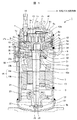
図1は、スクロール圧縮機の縦断面図である。 FIG. 1 is a longitudinal sectional view of a scroll compressor.
本図において、スクロール圧縮機1は、固定スクロール7(固定スクロール部材)、旋回スクロール8(旋回スクロール部材)、モータ部16(16a:回転子、16b:固定子)、シャフト10(回転軸)等をケース9(密閉容器)に収納した構成を有する。ケース9は、円筒形状である。
In this figure, the
本図に示すように、固定スクロール7は、円板状の台板7aと、この台板7aの片面に渦巻状に立設されたラップ7bと、台板7aの外周側に位置しラップ7bの先端面と連続する鏡板面7eを有しラップ7bを囲む筒状の支持部7dと、を含む。なお、ラップ7bは「歯」に見立てられるため、ラップ7bの先端面は、歯先と呼ばれ、ラップ7bが立設された台板7aの表面は、ラップ7bの間にあるため、歯底7cと呼ばれる。
As shown in the figure, the
また、支持部7dが旋回スクロール8の鏡板8aと接する面は、固定スクロール7の鏡板面7eとなっている。固定スクロール7は、その支持部7dがボルトなどによりフレーム17に固定され、固定スクロール7と一体となったフレーム17は溶接などの固定手段によりケース9に固定されている。
Further, the surface where the
旋回スクロール8は、固定スクロール7に対向して配置され、固定スクロール7のラップ7bと旋回スクロールのラップ8bとが噛み合わされて、フレーム17内に旋回可能に設けられている。旋回スクロール8は、円板状の鏡板8aと、この鏡板8aの表面である歯底8cから立設された渦巻状のラップ8bと、鏡板8aの背面中央に設けられたボス部8dと、を有する。また、鏡板8aの外周部の固定スクロール7と接する表面は、旋回スクロール8の鏡板面8eとなっている。
The orbiting
ケース9は、上キャップ9a及び下キャップ9bにより密閉されている。以下では、ケース9、上キャップ9a及び下キャップ9bを合わせて「密閉容器」と呼ぶことがある。密閉容器は、円筒形状であることが望ましい。
The
ケース9の内部には、固定スクロール7と旋回スクロール8とで構成されたスクロール部、モータ部16(16a:回転子、16b:固定子)および潤滑油などが収納されている。モータ部16の回転子16aと一体に固定されたシャフト10(回転軸)は、フレーム17に主軸受5を介して回転自在に支持され、固定スクロール7の中心軸線と同軸となっている。
Inside the
シャフト10の先端には、クランク部10aが設けられている。このクランク部10aは、旋回スクロール8の背面に設けられたボス部8dに挿入されている。旋回スクロール8は、シャフト10の回転に伴い、旋回可能に構成されている。クランク部10aとボス部8dとの間には、旋回軸受11が挟まれている。旋回スクロール8の中心軸線は、固定スクロール7の中心軸線に対して所定距離だけ偏心した状態となる。また、旋回スクロール8のラップ8bは、固定スクロール7のラップ7bに周方向に所定角度だけずらして重ね合わされている。さらに、旋回スクロール8を固定スクロール7に対して自転しないように拘束しながら相対的に旋回運動させるためのオルダムリング12が旋回スクロール8とフレーム17との間に組み合わされている。
A
図2は、固定スクロール7と旋回スクロール8との噛み合い状態を示す平面図である。
FIG. 2 is a plan view showing the meshed state of the
本図に示すように、ラップ7b,8b間には、三日月状の複数の圧縮室13(13a,13b)が形成されている。旋回スクロール8を旋回運動させると、各圧縮室は、中央部に移動するに従い、連続的に容積が縮小される。即ち、旋回スクロールラップ8bの内線側および外線側に、それぞれ旋回内線側圧縮室13aおよび旋回外線側圧縮室13bが形成される。符号20は、吸込室であり、流体を吸入している途中の空間である。この吸込室20は、旋回スクロール8の旋回運動の位相が進んで、流体の閉じ込みを完了した時点から圧縮室13となる。
As shown in the figure, a plurality of crescent-shaped compression chambers 13 (13a, 13b) are formed between the
吸込口14は、固定スクロール7に設けられている。この吸込口14は、吸込室20と連通するように台板7aの外周側に穿設されている。また、吐出口15は、最内周側の圧縮室13と連通するように固定スクロール7の台板7aの渦巻中心付近に穿設されている。
The
モータ部16によりシャフト10を回転駆動すると、シャフト10のクランク部10aから旋回軸受11を介して旋回スクロール8に伝えられ、旋回スクロール8は、固定スクロール7の中心軸線を中心に、所定距離の旋回半径をもって旋回運動する。この旋回運動時に旋回スクロール8が自転しないように、オルダムリング12によって拘束される。
When the
旋回スクロール8の旋回運動によって、各ラップ7b,8bの間にできる圧縮室13は、中央に連続的に移動し、その移動に従って圧縮室13の容積が連続的に縮小する。これにより、吸込口14から吸込まれた流体(例えば、冷凍サイクルを循環する冷媒ガス)を各圧縮室13内で順次圧縮し、圧縮された流体は吐出口15からケース上部の吐出空間54に吐出される。吐出された流体は、吐出空間54からフレーム7の外周側に単数または複数本設けられたフレーム外周通路17aを通り、ケース9内のモータ室52に入り、吐出パイプ6から圧縮機の外部、例えば冷凍サイクルに供給される。ここで、フレーム外周通路17aの入り口は、吐出空間54からの排出部であり、台板7aの上面に設けてある。
By the orbiting motion of the
なお、スクロール圧縮機以外の圧縮機においては、固定スクロール部材に対応する固定部材と、旋回スクロール部材に対応する可動部材と、を用い、これらの間に作動流体の圧縮室が形成される。 In a compressor other than the scroll compressor, a fixed member corresponding to the fixed scroll member and a movable member corresponding to the orbiting scroll member are used, and a working fluid compression chamber is formed therebetween.
図1に示すように、潤滑油は、ケース9の底部に貯留されている。シャフト10の下端には、容積型または遠心式の給油ポンプ21を設けている。シャフトの回転により給油ポンプ21も作動させ、潤滑油を給油ポンプケース22に設けた潤滑油吸込口25から吸入して、給油ポンプ21の吐出口28から吐出する。吐出された潤滑油は、シャフトに設けた貫通穴3を通って上部へ供給される。潤滑油の一部は、シャフト10に設けた横穴24を通って副軸受23を潤滑し、ケース底部の油溜り53に戻る。その他大部分の潤滑油は、貫通穴3を通ってシャフト10のクランク10a上部に達し、クランク10aに設けた油溝57を通って旋回軸受11を潤滑する。そして、旋回軸受11の下部に設けた主軸受5を潤滑した後、排油穴26aおよび排油パイプ26bを通ってケース底部の油溜まり53へ戻る。
As shown in FIG. 1, the lubricating oil is stored at the bottom of the
ここで、油溝57、旋回軸受11で形成される空間と、主軸受5を収める空間(フレーム17、シャフト10、フレームシール56、旋回スクロール8のボス部8dに設けられたつば形状の旋回ボス部材34、シール部材32で形成された空間)とをあわせて、第1の空間33と呼ぶことにする。この第1の空間33は、吐出圧力に近い圧力を有する空間である。主軸受5および旋回軸受11の潤滑のために第1の空間33に流入した潤滑油の大部分は、排油穴26aおよび排油パイプ26bを通ってケース底部へ戻るが、一部の潤滑油は、オルダムリング12の潤滑、及び固定スクロール7と旋回スクロール8との摺動部の潤滑に使われる。シールに必要な最低限の量の潤滑油が、シール部材32の上端面と旋回ボス部材34との端面間の後述の油漏出手段を介して背圧室18に入る。背圧室18は、第2の空間と呼ぶことにする。
Here, a space formed by the
シール部材32は、フレーム17に設けられた円環溝31に波状バネ(図示せず)と共に挿入されており、吐出圧力となっている第1の空間33と、吸込圧力と吐出圧力との間の圧力となっている背圧室18とを仕切っている。油漏出手段は、例えば旋回ボス部材34に設けられた複数の穴30とシール部材32とで構成される。複数の穴30は、旋回スクロール8の旋回運動に伴い、シール部材32を跨いだ円運動を行い、第1の空間33と背圧室18との間を移動する。これにより、第1の空間33の潤滑油を穴30に溜め、背圧室18へ間欠的に移送することにより、必要最小限の油を背圧室18に導くことができる。複数の穴30の代わりにスリットなどを設けて背圧室への油漏出手段としても良い。
The
背圧室18に入った潤滑油は、背圧が高くなると、背圧室18と圧縮室13とを連通する背圧孔35を通って圧縮室13へ入り、その後、吐出口15から吐出空間54へ吐出され、一部は、例えば冷媒ガスと共に吐出パイプ6から冷凍サイクルへ吐出され、残りはケース9内で冷媒ガスと分離されてケース底の油溜り53に貯留される。ケース9内において冷媒ガスから潤滑油を分離する割合(分離率)が向上すれば、吐出パイプ6から冷凍サイクルへ吐出される潤滑油を低減することができる。
When the back pressure increases, the lubricating oil that has entered the
次に、上述のスクロール圧縮機1における冷媒ガスと潤滑油との分離の詳細について説明する。
Next, details of separation of the refrigerant gas and the lubricating oil in the
スクロール圧縮機1においては、ケース9内に流入する潤滑油は、主として背圧室18を経由し、固定スクロール7と旋回スクロール8との摺動部の潤滑およびシールを行い、圧縮室13に入った後、吐出口15から吐出空間54へ冷媒ガスと共に吐出される。吐出される冷媒ガス中の潤滑油は、主として微小液滴状態で冷媒ガス中に分散して存在している。
In the
冷媒ガスからの潤滑油の分離は、主として上キャップ9aの内壁面に冷媒ガス及び潤滑油が衝突する際に、慣性効果により潤滑油が壁面へ衝突付着することで分離される。壁面へ衝突付着した潤滑油は、壁面に沿って重力方向に流下し、最終的にケース底の油溜り53に貯留される。
Separation of the lubricating oil from the refrigerant gas is mainly performed when the refrigerant gas and the lubricating oil collide with the inner wall surface of the
冷媒ガス中に含まれる潤滑油の壁面への付着率を高めるためには、潤滑油の液滴の慣性エネルギを大きくすることが有効である。慣性エネルギが大きいと、冷媒ガスが壁面に衝突し、流れ方向が変化する際に、潤滑油が冷媒ガスの流れに追従しきれずに壁面へ衝突する割合が高まる。慣性エネルギが小さい場合は、潤滑油は冷媒ガスの流れに追従しやすくなり、壁面への衝突割合は低下する。慣性エネルギを高めるためには、潤滑油の液滴の運動速度を上げることが有効である。ある冷媒ガス流量においては、流路断面積が小さいほうが冷媒ガス流速および冷媒ガス流れに追従して移動する潤滑油の液滴の運動速度を上げることができる。ノズルから空間中へガス噴流が吐出する場合を考えると、ガス噴流は、ノズル出口から距離が大きくなるに従い、拡散により流速が低下するため、ノズル出口と壁面との距離が近いほど、衝突するガスの流速を大きく取ることができる。 In order to increase the adhesion rate of the lubricating oil contained in the refrigerant gas to the wall surface, it is effective to increase the inertial energy of the lubricating oil droplets. When the inertial energy is large, when the refrigerant gas collides with the wall surface and the flow direction changes, the ratio of the lubricating oil colliding with the wall surface without following the refrigerant gas flow increases. When the inertial energy is small, the lubricating oil easily follows the flow of the refrigerant gas, and the rate of collision with the wall surface decreases. In order to increase the inertial energy, it is effective to increase the motion speed of the lubricant droplets. At a certain refrigerant gas flow rate, the smaller the flow path cross-sectional area, the higher the moving speed of the lubricating oil droplets moving following the refrigerant gas flow rate and the refrigerant gas flow. Considering the case where a gas jet is discharged from the nozzle into the space, the gas jet has a flow velocity that decreases due to diffusion as the distance from the nozzle outlet increases. The flow rate of can be increased.
本実施例では、吐出空間54において、吐出口15の後流側に、吐出口15と一体または別体で形成された誘導流路60を設け、誘導流路60は回転軸方向から見て半径方向に冷媒流が吐出されるようにケース9内壁面に向け流路が形成されている。誘導流路60の半径方向の出口は、吐出空間54に開口した開口部60aである。開口部60aからケース9内壁面までの距離は、吐出口15出口とケース9内壁面との距離以下となるような位置に設置される。これにより、冷媒ガス噴流の拡散の影響を低減し、従来構造より冷媒ガスのケース9内壁面への衝突速度が上がり、潤滑油の壁面への付着量が増え分離効率が高まり、吐出パイプ6から冷凍サイクルへ吐出される潤滑油を低減することができる。
In the present embodiment, in the discharge space 54, a
一般に、開口部60aは、作動流体が密閉容器の中心軸から離れる方向に向かうように設けられていることが望ましい。
In general, it is desirable that the
図1においては、誘導流路60は、回転軸を基準としてほぼ半径方向に作動流体を流し、開口部60aから当該半径方向に作動流体を流出させるように構成されている。この場合、流出した作動流体は、ケース9又は上キャップ9aの内壁面に衝突した後、吐出空間54に広がる。回転軸を基準として開口部60aから180°回転した位置にフレーム外周通路17aの入り口(吐出空間からの排出部)を設ければ、広がった作動流体が開口部60aから最も遠い位置まで旋回することになるため望ましい。
In FIG. 1, the
なお、本発明の誘導流路60及びその開口部60aは、図1の例に限定されるものではなく、上キャップ9aの頂部に向けた構成(回転軸の中心軸方向に向けた構成、すなわち台板7aの表面を基準として仰角90°)としてもよいし、当該仰角を90℃未満として上キャップ9aの内壁面に作動流体を衝突させる構成としてもよい。いずれの場合も、開口部60aとフレーム外周通路17aの入り口(吐出空間からの排出部)との距離を可能な限り大きくするように位置関係を調整するにより、作動流体を旋回させて潤滑油の分離効率を高めることができる。
The
この場合に、誘導流路60の半径方向流路断面積(開口部60aにおける流路断面積)は、壁面衝突位置での冷媒ガス流速が従来形状と比較して高速となる範囲で、吐出口15の出口断面積と同等もしくは大きくなるように設けることができる。
In this case, the radial flow path cross-sectional area of the guide flow path 60 (the flow path cross-sectional area at the
さらに、誘導流路60による圧力損失の影響が小さく、油分離効率の向上効果が優位な場合は、誘導流路60の半径方向流路断面積は、吐出口15の出口断面積以下となるように設置してもよい。これにより、冷媒ガス流速を更に加速することができ、潤滑油の壁面への付着量が増え、分離効率が高まり、吐出パイプ6から冷凍サイクルへ吐出される潤滑油を低減することができる。
Further, when the influence of the pressure loss due to the
一般に、誘導流路の開口部の流路断面積は、吐出口の流路断面積以下であることが望ましい。 Generally, it is desirable that the channel cross-sectional area of the opening portion of the guide channel is equal to or smaller than the channel cross-sectional area of the discharge port.
なお、誘導流路60は、本実施例で示すように、吐出口15を覆うようなカバー状で供されても良いし、固定スクロール台板7aからケース9内壁面まで立設されるような壁面で構成されても良い。
In addition, as shown in the present embodiment, the
上記の構成により、吐出口から吐出される潤滑油を含む作動流体(冷媒等)がその流路断面積の拡大を制限された状態で密閉容器の内壁面に衝突するようになる。 With the configuration described above, the working fluid (refrigerant or the like) including the lubricating oil discharged from the discharge port collides with the inner wall surface of the sealed container in a state where expansion of the flow path cross-sectional area is restricted.
誘導流路60は、例えば、薄板状の金属板をプレス加工し流路壁面を形成することができる。固定方法として、固定スクロールの台板7aに、溶接又はねじにより固定することで取り付けても良い。ただし、加工方法および固定方法はこれに限定されるものではなく、他の方法を用いて実施してもよい。
For example, the
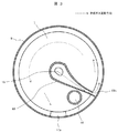
図3は、回転軸方向から見た固定スクロール7上面および誘導流路60の断面を示したものである。
FIG. 3 shows a cross section of the upper surface of the fixed
図3では、誘導流路60の周方向の開口部60bを、回転軸方向から見て一方向側のみに開口するように設けている。これにより、吐出空間54内に回転軸方向から見ていずれかの周方向の流れが形成されるとともに、流れが一方向に限定されることで、誘導流路60の周方向の開口部60bからフレーム外周通路17aに至る流路長を大きくすることができる。これにより、潤滑油の沈降による分離が促進される。
In FIG. 3, the
また、誘導流路60の開口部60a(図1)が、回転軸方向から見て、フレーム外周通路17aから周方向に最も遠い位置に設置されており、これにより誘導流路60の周方向の開口部60bからフレーム外周通路17aに至る流路長を最大化することができる。これにより、潤滑油の沈降による分離が更に促進される。
Further, the
図3に示すように、誘導流路60の開口部60bは、吐出空間からの排出部に対向していない。
As shown in FIG. 3, the
また、誘導流路60の流路断面積は、吐出口15の近くに比べ、ケース9の近くに向かうほど狭くなっている。これにより、開口部60bから流出する作動流体の流速を高め、旋回流に含まれる潤滑油の分離を促進することができる。
In addition, the cross-sectional area of the
図3に示すように、フレーム外周通路17aの入り口(吐出空間からの排出部)は、誘導流路60の開口部60bからの角度で、誘導流路60の開口部60bから流出した作動流体の旋回方向に270°以上の位置に設置することが望ましい。言い換えると、誘導流路60の開口部60bは、発生した旋回流が密閉容器の中心軸の周りに270°以上移動した後、吐出空間からの排出部に流入するように配置されていることが望ましい。
As shown in FIG. 3, the entrance (discharge portion from the discharge space) of the frame outer
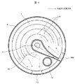
図4は、回転軸方向から見た固定スクロール7上面および誘導流路60の断面およびトラップ流路61の断面を示したものである。
FIG. 4 shows the top surface of the fixed
本実施例では、誘導流路60の下流側の吐出空間54において、同心円状またはらせん状またはそれに類する曲線状のトラップ流路壁61を備えている。トラップ流路壁61により吐出空間54内の旋回流れの誘導を促進するとともに、潤滑油を含む冷媒ガス流れが壁面と接する面積を大きくすることで壁面への潤滑油の付着が増え、潤滑油の分離が促進される。なお、トラップ流路壁61は、金網や多孔壁などの冷媒ガス流れを部分的に透過するような部材で構成されていてもよい。
In the present embodiment, the discharge space 54 on the downstream side of the
また、トラップ流路壁61を誘導流路60の半径方向端面として用いて、ケース9内壁面ではなくトラップ流路壁61に冷媒ガス流れが衝突するように構成してもよい。
Alternatively, the
1:スクロール圧縮機、3:貫通穴、5:主軸受、6:吐出パイプ、7:固定スクロール、7a:台板、7b:ラップ、7c:歯底、7d:支持部、7e:鏡板面、8:旋回スクロール、8a:鏡板、8b:ラップ、8c:歯底、8d:ボス部、8e:鏡板面、9:ケース、9a:上キャップ、9b:下キャップ、10:シャフト、10a:クランク部、11:旋回軸受、12:オルダムリング、13:圧縮室、13a:旋回内線側圧縮室、13b:旋回外線側圧縮室、14:吸込口、15:吐出口、16:モータ部、16a:回転子、16b:固定子、17:フレーム、17a:フレーム外周通路、18:背圧室、20:吸込室、21:給油ポンプ、23:副軸受、30:穴、32:シール部材、33:第1の空間、34:旋回ボス部材、35:背圧孔、52:モータ室、53:油溜り、54:吐出空間、56:フレームシール、60:誘導流路、60a:開口部、60b:周方向の開口部、61:トラップ流路壁。 1: scroll compressor, 3: through hole, 5: main bearing, 6: discharge pipe, 7: fixed scroll, 7a: base plate, 7b: wrap, 7c: tooth bottom, 7d: support, 7e: end plate surface, 8: Orbiting scroll, 8a: End plate, 8b: Lap, 8c: Tooth base, 8d: Boss part, 8e: End face, 9: Case, 9a: Upper cap, 9b: Lower cap, 10: Shaft, 10a: Crank part , 11: slewing bearing, 12: Oldham ring, 13: compression chamber, 13a: internal line side compression chamber, 13b: external line side compression chamber, 14: suction port, 15: discharge port, 16: motor part, 16a: rotation Child, 16b: Stator, 17: Frame, 17a: Frame outer peripheral passage, 18: Back pressure chamber, 20: Suction chamber, 21: Oil pump, 23: Sub bearing, 30: Hole, 32: Seal member, 33: No. 1 space 34: swivel boss member, 5: Back pressure hole, 52: Motor chamber, 53: Oil reservoir, 54: Discharge space, 56: Frame seal, 60: Guide channel, 60a: Opening, 60b: Opening in the circumferential direction, 61: Trap channel wall.
Claims (10)
前記固定部材に設けられ、前記圧縮室で圧縮された作動流体を吐出する吐出口と、
前記吐出口の下流に設けられる吐出空間と、
圧縮された作動流体を前記吐出口から前記密閉容器の内壁面へ導くとともに、前記吐出口から前記内壁面までの間に流路面積が小さくなる誘導流路と、
前記吐出空間から作動流体を排出する排出部と、
前記誘導流路を通過した作動流体を旋回させて前記排出部まで導く流路壁と、を備える圧縮機。 In a compressor including a fixed member and a movable member in a sealed container, and a compression chamber for compressing a working fluid is formed by the fixed member and the movable member.
A discharge port that is provided in the fixing member and discharges the working fluid compressed in the compression chamber;
A discharge space provided downstream of the discharge port;
Guiding the compressed working fluid from the discharge port to the inner wall surface of the hermetic container, and a guide channel having a smaller flow path area from the discharge port to the inner wall surface;
A discharge part for discharging the working fluid from the discharge space;
And a flow path wall that swirls the working fluid that has passed through the guide flow path and guides it to the discharge portion.
前記可動部材は、旋回スクロールであり、
これらがスクロール圧縮機を構成する、請求項1〜9のいずれか一項に記載の圧縮機。 The fixed member is a fixed scroll;
The movable member is an orbiting scroll;
The compressor according to any one of claims 1 to 9, wherein these constitute a scroll compressor.
Priority Applications (1)
| Application Number | Priority Date | Filing Date | Title |
|---|---|---|---|
| JP2015058904A JP2016176449A (en) | 2015-03-23 | 2015-03-23 | Compressor |
Applications Claiming Priority (1)
| Application Number | Priority Date | Filing Date | Title |
|---|---|---|---|
| JP2015058904A JP2016176449A (en) | 2015-03-23 | 2015-03-23 | Compressor |
Publications (2)
| Publication Number | Publication Date |
|---|---|
| JP2016176449A true JP2016176449A (en) | 2016-10-06 |
| JP2016176449A5 JP2016176449A5 (en) | 2017-07-27 |
Family
ID=57070989
Family Applications (1)
| Application Number | Title | Priority Date | Filing Date |
|---|---|---|---|
| JP2015058904A Pending JP2016176449A (en) | 2015-03-23 | 2015-03-23 | Compressor |
Country Status (1)
| Country | Link |
|---|---|
| JP (1) | JP2016176449A (en) |
Cited By (3)
| Publication number | Priority date | Publication date | Assignee | Title |
|---|---|---|---|---|
| WO2018020992A1 (en) * | 2016-07-28 | 2018-02-01 | パナソニックIpマネジメント株式会社 | Compressor |
| JP2019074045A (en) * | 2017-10-17 | 2019-05-16 | 日立ジョンソンコントロールズ空調株式会社 | Displacement type compressor |
| JP2020045845A (en) * | 2018-09-20 | 2020-03-26 | 日立ジョンソンコントロールズ空調株式会社 | Hermetic electric compressor |
Citations (11)
| Publication number | Priority date | Publication date | Assignee | Title |
|---|---|---|---|---|
| JPS61179389U (en) * | 1985-04-27 | 1986-11-08 | ||
| JPS63192984A (en) * | 1987-02-03 | 1988-08-10 | Matsushita Refrig Co | Scroll type compressor |
| JPH0447188U (en) * | 1990-08-28 | 1992-04-22 | ||
| JPH04203488A (en) * | 1990-11-30 | 1992-07-24 | Hitachi Ltd | Hermetic oil supplying type scroll compressor |
| JPH0610852A (en) * | 1992-06-30 | 1994-01-21 | Daikin Ind Ltd | Scroll compressor |
| JPH08151990A (en) * | 1994-11-30 | 1996-06-11 | Daikin Ind Ltd | Scroll fluid device |
| JP2000345978A (en) * | 1999-05-31 | 2000-12-12 | Mitsubishi Heavy Ind Ltd | Scroll compressor |
| JP2005180297A (en) * | 2003-12-19 | 2005-07-07 | Mitsubishi Heavy Ind Ltd | Scroll compressor |
| JP2008128035A (en) * | 2006-11-17 | 2008-06-05 | Sanden Corp | Sealed compressor |
| JP2010223155A (en) * | 2009-03-25 | 2010-10-07 | Panasonic Corp | Hermetic compressor |
| JP2011226296A (en) * | 2010-04-15 | 2011-11-10 | Daikin Industries Ltd | Compressor |
-
2015
- 2015-03-23 JP JP2015058904A patent/JP2016176449A/en active Pending
Patent Citations (11)
| Publication number | Priority date | Publication date | Assignee | Title |
|---|---|---|---|---|
| JPS61179389U (en) * | 1985-04-27 | 1986-11-08 | ||
| JPS63192984A (en) * | 1987-02-03 | 1988-08-10 | Matsushita Refrig Co | Scroll type compressor |
| JPH0447188U (en) * | 1990-08-28 | 1992-04-22 | ||
| JPH04203488A (en) * | 1990-11-30 | 1992-07-24 | Hitachi Ltd | Hermetic oil supplying type scroll compressor |
| JPH0610852A (en) * | 1992-06-30 | 1994-01-21 | Daikin Ind Ltd | Scroll compressor |
| JPH08151990A (en) * | 1994-11-30 | 1996-06-11 | Daikin Ind Ltd | Scroll fluid device |
| JP2000345978A (en) * | 1999-05-31 | 2000-12-12 | Mitsubishi Heavy Ind Ltd | Scroll compressor |
| JP2005180297A (en) * | 2003-12-19 | 2005-07-07 | Mitsubishi Heavy Ind Ltd | Scroll compressor |
| JP2008128035A (en) * | 2006-11-17 | 2008-06-05 | Sanden Corp | Sealed compressor |
| JP2010223155A (en) * | 2009-03-25 | 2010-10-07 | Panasonic Corp | Hermetic compressor |
| JP2011226296A (en) * | 2010-04-15 | 2011-11-10 | Daikin Industries Ltd | Compressor |
Cited By (5)
| Publication number | Priority date | Publication date | Assignee | Title |
|---|---|---|---|---|
| WO2018020992A1 (en) * | 2016-07-28 | 2018-02-01 | パナソニックIpマネジメント株式会社 | Compressor |
| JPWO2018020992A1 (en) * | 2016-07-28 | 2019-05-16 | パナソニックIpマネジメント株式会社 | Compressor |
| JP7113353B2 (en) | 2016-07-28 | 2022-08-05 | パナソニックIpマネジメント株式会社 | compressor |
| JP2019074045A (en) * | 2017-10-17 | 2019-05-16 | 日立ジョンソンコントロールズ空調株式会社 | Displacement type compressor |
| JP2020045845A (en) * | 2018-09-20 | 2020-03-26 | 日立ジョンソンコントロールズ空調株式会社 | Hermetic electric compressor |
Similar Documents
| Publication | Publication Date | Title |
|---|---|---|
| EP3358191B1 (en) | Co-rotating scroll compressor | |
| JP3170109B2 (en) | Scroll type compressor | |
| JP5039869B1 (en) | Compressor | |
| JP2013137030A (en) | Compressor | |
| JP6745992B2 (en) | Scroll compressor and refrigeration cycle device | |
| JP2016176449A (en) | Compressor | |
| US20200149548A1 (en) | Compressor | |
| JP3925229B2 (en) | Hermetic scroll compressor, refrigeration cycle and refrigeration apparatus using the same | |
| WO2020170886A1 (en) | Hermetically sealed compressor | |
| JP6143862B2 (en) | Scroll compressor and air conditioner using the same | |
| JP2001248577A (en) | Scroll type fluid machine | |
| JP6785594B2 (en) | Sealed scroll compressor | |
| JP4164917B2 (en) | High pressure dome compressor | |
| JP5494691B2 (en) | Compressor | |
| WO2018051750A1 (en) | Scroll compressor | |
| JP2016217233A (en) | Scroll compressor | |
| JP4699270B2 (en) | Scroll compressor | |
| JP6108276B2 (en) | Compressor | |
| JP2014095326A (en) | Scroll compressor | |
| US11293440B2 (en) | Compressor | |
| JP5540577B2 (en) | Scroll compressor | |
| WO2021025033A1 (en) | Scroll compressor | |
| JP2010065560A (en) | Scroll compressor | |
| JP6120173B2 (en) | Compressor | |
| JP2020033908A (en) | Scroll compressor |
Legal Events
| Date | Code | Title | Description |
|---|---|---|---|
| A521 | Request for written amendment filed |
Free format text: JAPANESE INTERMEDIATE CODE: A523 Effective date: 20170616 |
|
| A621 | Written request for application examination |
Free format text: JAPANESE INTERMEDIATE CODE: A621 Effective date: 20170616 |
|
| A711 | Notification of change in applicant |
Free format text: JAPANESE INTERMEDIATE CODE: A711 Effective date: 20171018 |
|
| A977 | Report on retrieval |
Free format text: JAPANESE INTERMEDIATE CODE: A971007 Effective date: 20180412 |
|
| A131 | Notification of reasons for refusal |
Free format text: JAPANESE INTERMEDIATE CODE: A131 Effective date: 20180522 |
|
| A521 | Request for written amendment filed |
Free format text: JAPANESE INTERMEDIATE CODE: A523 Effective date: 20180720 |
|
| A131 | Notification of reasons for refusal |
Free format text: JAPANESE INTERMEDIATE CODE: A131 Effective date: 20181211 |
|
| A02 | Decision of refusal |
Free format text: JAPANESE INTERMEDIATE CODE: A02 Effective date: 20190611 |