WO2016051818A1 - 障害物回避システム - Google Patents
障害物回避システム Download PDFInfo
- Publication number
- WO2016051818A1 WO2016051818A1 PCT/JP2015/056702 JP2015056702W WO2016051818A1 WO 2016051818 A1 WO2016051818 A1 WO 2016051818A1 JP 2015056702 W JP2015056702 W JP 2015056702W WO 2016051818 A1 WO2016051818 A1 WO 2016051818A1
- Authority
- WO
- WIPO (PCT)
- Prior art keywords
- obstacle
- vehicle
- travel
- avoidance
- host vehicle
- Prior art date
Links
- 238000001514 detection method Methods 0.000 claims description 50
- 230000001133 acceleration Effects 0.000 claims description 8
- 230000002452 interceptive effect Effects 0.000 abstract description 2
- 238000004891 communication Methods 0.000 description 24
- 238000000034 method Methods 0.000 description 22
- 238000010586 diagram Methods 0.000 description 20
- 230000008569 process Effects 0.000 description 16
- 238000012545 processing Methods 0.000 description 15
- 230000006870 function Effects 0.000 description 12
- 230000008859 change Effects 0.000 description 3
- 230000000694 effects Effects 0.000 description 2
- 239000011435 rock Substances 0.000 description 2
- 230000007704 transition Effects 0.000 description 2
- 230000009471 action Effects 0.000 description 1
- 238000013459 approach Methods 0.000 description 1
- 230000005540 biological transmission Effects 0.000 description 1
- 230000000903 blocking effect Effects 0.000 description 1
- 239000000470 constituent Substances 0.000 description 1
- 230000007423 decrease Effects 0.000 description 1
- 230000003247 decreasing effect Effects 0.000 description 1
- 239000000446 fuel Substances 0.000 description 1
- 230000005764 inhibitory process Effects 0.000 description 1
- 238000002347 injection Methods 0.000 description 1
- 239000007924 injection Substances 0.000 description 1
- 239000004973 liquid crystal related substance Substances 0.000 description 1
- 238000012423 maintenance Methods 0.000 description 1
- 238000004519 manufacturing process Methods 0.000 description 1
- 239000007787 solid Substances 0.000 description 1
- XLYOFNOQVPJJNP-UHFFFAOYSA-N water Substances O XLYOFNOQVPJJNP-UHFFFAOYSA-N 0.000 description 1
Images


Classifications
-
- G—PHYSICS
- G08—SIGNALLING
- G08G—TRAFFIC CONTROL SYSTEMS
- G08G1/00—Traffic control systems for road vehicles
- G08G1/16—Anti-collision systems
- G08G1/165—Anti-collision systems for passive traffic, e.g. including static obstacles, trees
-
- B—PERFORMING OPERATIONS; TRANSPORTING
- B60—VEHICLES IN GENERAL
- B60W—CONJOINT CONTROL OF VEHICLE SUB-UNITS OF DIFFERENT TYPE OR DIFFERENT FUNCTION; CONTROL SYSTEMS SPECIALLY ADAPTED FOR HYBRID VEHICLES; ROAD VEHICLE DRIVE CONTROL SYSTEMS FOR PURPOSES NOT RELATED TO THE CONTROL OF A PARTICULAR SUB-UNIT
- B60W30/00—Purposes of road vehicle drive control systems not related to the control of a particular sub-unit, e.g. of systems using conjoint control of vehicle sub-units, or advanced driver assistance systems for ensuring comfort, stability and safety or drive control systems for propelling or retarding the vehicle
- B60W30/08—Active safety systems predicting or avoiding probable or impending collision or attempting to minimise its consequences
- B60W30/09—Taking automatic action to avoid collision, e.g. braking and steering
-
- B—PERFORMING OPERATIONS; TRANSPORTING
- B60—VEHICLES IN GENERAL
- B60W—CONJOINT CONTROL OF VEHICLE SUB-UNITS OF DIFFERENT TYPE OR DIFFERENT FUNCTION; CONTROL SYSTEMS SPECIALLY ADAPTED FOR HYBRID VEHICLES; ROAD VEHICLE DRIVE CONTROL SYSTEMS FOR PURPOSES NOT RELATED TO THE CONTROL OF A PARTICULAR SUB-UNIT
- B60W30/00—Purposes of road vehicle drive control systems not related to the control of a particular sub-unit, e.g. of systems using conjoint control of vehicle sub-units, or advanced driver assistance systems for ensuring comfort, stability and safety or drive control systems for propelling or retarding the vehicle
- B60W30/10—Path keeping
- B60W30/12—Lane keeping
-
- B—PERFORMING OPERATIONS; TRANSPORTING
- B60—VEHICLES IN GENERAL
- B60W—CONJOINT CONTROL OF VEHICLE SUB-UNITS OF DIFFERENT TYPE OR DIFFERENT FUNCTION; CONTROL SYSTEMS SPECIALLY ADAPTED FOR HYBRID VEHICLES; ROAD VEHICLE DRIVE CONTROL SYSTEMS FOR PURPOSES NOT RELATED TO THE CONTROL OF A PARTICULAR SUB-UNIT
- B60W30/00—Purposes of road vehicle drive control systems not related to the control of a particular sub-unit, e.g. of systems using conjoint control of vehicle sub-units, or advanced driver assistance systems for ensuring comfort, stability and safety or drive control systems for propelling or retarding the vehicle
- B60W30/18—Propelling the vehicle
- B60W30/18009—Propelling the vehicle related to particular drive situations
- B60W30/18163—Lane change; Overtaking manoeuvres
-
- B—PERFORMING OPERATIONS; TRANSPORTING
- B62—LAND VEHICLES FOR TRAVELLING OTHERWISE THAN ON RAILS
- B62D—MOTOR VEHICLES; TRAILERS
- B62D15/00—Steering not otherwise provided for
- B62D15/02—Steering position indicators ; Steering position determination; Steering aids
-
- B—PERFORMING OPERATIONS; TRANSPORTING
- B62—LAND VEHICLES FOR TRAVELLING OTHERWISE THAN ON RAILS
- B62D—MOTOR VEHICLES; TRAILERS
- B62D15/00—Steering not otherwise provided for
- B62D15/02—Steering position indicators ; Steering position determination; Steering aids
- B62D15/025—Active steering aids, e.g. helping the driver by actively influencing the steering system after environment evaluation
- B62D15/0265—Automatic obstacle avoidance by steering
-
- G—PHYSICS
- G01—MEASURING; TESTING
- G01C—MEASURING DISTANCES, LEVELS OR BEARINGS; SURVEYING; NAVIGATION; GYROSCOPIC INSTRUMENTS; PHOTOGRAMMETRY OR VIDEOGRAMMETRY
- G01C21/00—Navigation; Navigational instruments not provided for in groups G01C1/00 - G01C19/00
- G01C21/26—Navigation; Navigational instruments not provided for in groups G01C1/00 - G01C19/00 specially adapted for navigation in a road network
- G01C21/34—Route searching; Route guidance
- G01C21/3407—Route searching; Route guidance specially adapted for specific applications
-
- G—PHYSICS
- G01—MEASURING; TESTING
- G01S—RADIO DIRECTION-FINDING; RADIO NAVIGATION; DETERMINING DISTANCE OR VELOCITY BY USE OF RADIO WAVES; LOCATING OR PRESENCE-DETECTING BY USE OF THE REFLECTION OR RERADIATION OF RADIO WAVES; ANALOGOUS ARRANGEMENTS USING OTHER WAVES
- G01S13/00—Systems using the reflection or reradiation of radio waves, e.g. radar systems; Analogous systems using reflection or reradiation of waves whose nature or wavelength is irrelevant or unspecified
- G01S13/88—Radar or analogous systems specially adapted for specific applications
- G01S13/93—Radar or analogous systems specially adapted for specific applications for anti-collision purposes
- G01S13/931—Radar or analogous systems specially adapted for specific applications for anti-collision purposes of land vehicles
-
- G—PHYSICS
- G01—MEASURING; TESTING
- G01S—RADIO DIRECTION-FINDING; RADIO NAVIGATION; DETERMINING DISTANCE OR VELOCITY BY USE OF RADIO WAVES; LOCATING OR PRESENCE-DETECTING BY USE OF THE REFLECTION OR RERADIATION OF RADIO WAVES; ANALOGOUS ARRANGEMENTS USING OTHER WAVES
- G01S17/00—Systems using the reflection or reradiation of electromagnetic waves other than radio waves, e.g. lidar systems
- G01S17/86—Combinations of lidar systems with systems other than lidar, radar or sonar, e.g. with direction finders
-
- G—PHYSICS
- G01—MEASURING; TESTING
- G01S—RADIO DIRECTION-FINDING; RADIO NAVIGATION; DETERMINING DISTANCE OR VELOCITY BY USE OF RADIO WAVES; LOCATING OR PRESENCE-DETECTING BY USE OF THE REFLECTION OR RERADIATION OF RADIO WAVES; ANALOGOUS ARRANGEMENTS USING OTHER WAVES
- G01S17/00—Systems using the reflection or reradiation of electromagnetic waves other than radio waves, e.g. lidar systems
- G01S17/88—Lidar systems specially adapted for specific applications
- G01S17/93—Lidar systems specially adapted for specific applications for anti-collision purposes
- G01S17/931—Lidar systems specially adapted for specific applications for anti-collision purposes of land vehicles
-
- G—PHYSICS
- G01—MEASURING; TESTING
- G01S—RADIO DIRECTION-FINDING; RADIO NAVIGATION; DETERMINING DISTANCE OR VELOCITY BY USE OF RADIO WAVES; LOCATING OR PRESENCE-DETECTING BY USE OF THE REFLECTION OR RERADIATION OF RADIO WAVES; ANALOGOUS ARRANGEMENTS USING OTHER WAVES
- G01S5/00—Position-fixing by co-ordinating two or more direction or position line determinations; Position-fixing by co-ordinating two or more distance determinations
- G01S5/0009—Transmission of position information to remote stations
- G01S5/0072—Transmission between mobile stations, e.g. anti-collision systems
-
- G—PHYSICS
- G05—CONTROLLING; REGULATING
- G05D—SYSTEMS FOR CONTROLLING OR REGULATING NON-ELECTRIC VARIABLES
- G05D1/00—Control of position, course or altitude of land, water, air, or space vehicles, e.g. automatic pilot
- G05D1/02—Control of position or course in two dimensions
- G05D1/021—Control of position or course in two dimensions specially adapted to land vehicles
- G05D1/0257—Control of position or course in two dimensions specially adapted to land vehicles using a radar
-
- G—PHYSICS
- G05—CONTROLLING; REGULATING
- G05D—SYSTEMS FOR CONTROLLING OR REGULATING NON-ELECTRIC VARIABLES
- G05D1/00—Control of position, course or altitude of land, water, air, or space vehicles, e.g. automatic pilot
- G05D1/02—Control of position or course in two dimensions
- G05D1/021—Control of position or course in two dimensions specially adapted to land vehicles
- G05D1/0268—Control of position or course in two dimensions specially adapted to land vehicles using internal positioning means
- G05D1/0274—Control of position or course in two dimensions specially adapted to land vehicles using internal positioning means using mapping information stored in a memory device
-
- G—PHYSICS
- G05—CONTROLLING; REGULATING
- G05D—SYSTEMS FOR CONTROLLING OR REGULATING NON-ELECTRIC VARIABLES
- G05D1/00—Control of position, course or altitude of land, water, air, or space vehicles, e.g. automatic pilot
- G05D1/02—Control of position or course in two dimensions
- G05D1/021—Control of position or course in two dimensions specially adapted to land vehicles
- G05D1/0287—Control of position or course in two dimensions specially adapted to land vehicles involving a plurality of land vehicles, e.g. fleet or convoy travelling
- G05D1/0291—Fleet control
- G05D1/0297—Fleet control by controlling means in a control room
-
- G—PHYSICS
- G08—SIGNALLING
- G08G—TRAFFIC CONTROL SYSTEMS
- G08G1/00—Traffic control systems for road vehicles
- G08G1/16—Anti-collision systems
-
- G—PHYSICS
- G08—SIGNALLING
- G08G—TRAFFIC CONTROL SYSTEMS
- G08G1/00—Traffic control systems for road vehicles
- G08G1/16—Anti-collision systems
- G08G1/166—Anti-collision systems for active traffic, e.g. moving vehicles, pedestrians, bikes
-
- G—PHYSICS
- G08—SIGNALLING
- G08G—TRAFFIC CONTROL SYSTEMS
- G08G1/00—Traffic control systems for road vehicles
- G08G1/20—Monitoring the location of vehicles belonging to a group, e.g. fleet of vehicles, countable or determined number of vehicles
- G08G1/207—Monitoring the location of vehicles belonging to a group, e.g. fleet of vehicles, countable or determined number of vehicles with respect to certain areas, e.g. forbidden or allowed areas with possible alerting when inside or outside boundaries
-
- B—PERFORMING OPERATIONS; TRANSPORTING
- B60—VEHICLES IN GENERAL
- B60W—CONJOINT CONTROL OF VEHICLE SUB-UNITS OF DIFFERENT TYPE OR DIFFERENT FUNCTION; CONTROL SYSTEMS SPECIALLY ADAPTED FOR HYBRID VEHICLES; ROAD VEHICLE DRIVE CONTROL SYSTEMS FOR PURPOSES NOT RELATED TO THE CONTROL OF A PARTICULAR SUB-UNIT
- B60W2554/00—Input parameters relating to objects
- B60W2554/80—Spatial relation or speed relative to objects
-
- G—PHYSICS
- G01—MEASURING; TESTING
- G01S—RADIO DIRECTION-FINDING; RADIO NAVIGATION; DETERMINING DISTANCE OR VELOCITY BY USE OF RADIO WAVES; LOCATING OR PRESENCE-DETECTING BY USE OF THE REFLECTION OR RERADIATION OF RADIO WAVES; ANALOGOUS ARRANGEMENTS USING OTHER WAVES
- G01S19/00—Satellite radio beacon positioning systems; Determining position, velocity or attitude using signals transmitted by such systems
- G01S19/01—Satellite radio beacon positioning systems transmitting time-stamped messages, e.g. GPS [Global Positioning System], GLONASS [Global Orbiting Navigation Satellite System] or GALILEO
- G01S19/13—Receivers
Definitions
- the present invention relates to an obstacle avoidance system, and more particularly to an obstacle avoidance system in a conveyance path including a plurality of lanes.
- an autonomous traveling system in which a transportation vehicle (hereinafter referred to as “unmanned dump truck”) that autonomously travels without boarding an operator is connected to a control device via a wireless communication line.
- the driving position and work status of unmanned dump trucks, graders, dozers, service cars, water trucks, etc. that are operated by operators (hereinafter referred to as “manned vehicles”) are managed by the autonomous driving system. Is controlled based on the map data generated in advance and the travel position.
- Patent Document 1 discloses that “a relative position between an own vehicle and an obstacle ahead of the own vehicle is detected in order to perform accurate cooperative control of automatic brake control and steering assist control.
- automatic brake control is performed, and the relative position with the detected obstacle is the first position.
- a technique of performing steering assist control when the vehicle is in the second region wide in the vehicle width direction outside the region "(see abstract) is disclosed.
- Patent Document 1 the obstacle avoidance operation is performed based only on the positional relationship with the obstacle in front of the host vehicle that can be detected by a sensor such as a radar mounted on the vehicle. Even when there is an incoming vehicle, there is a risk of determining that avoidance steering to the oncoming lane is permitted. Depending on the positional relationship with the oncoming vehicle and the amount of protrusion to the oncoming lane, there is a risk of contact with the oncoming vehicle, and even if there is no contact, the efficiency of the conveyance work may be reduced due to unscheduled deceleration, etc. Although there is a problem, Patent Literature 1 does not consider this point.
- the present invention has been made in view of the above situation, and in avoiding obstacles on the traveling road, it is safe and efficient without obstructing the traveling of the vehicle on the adjacent lane arranged side by side with the traveling lane of the own vehicle.
- the objective is to avoid obstacles.
- the present invention is arranged such that the traveling lane and the adjacent lane of the host vehicle are arranged side by side, and an obstacle in front of the traveling lane passes through the adjacent lane side of the obstacle.
- An obstacle avoidance system for avoiding, based on an output from an external sensor mounted on the host vehicle, a relative position of the obstacle with respect to the host vehicle, and a vehicle width direction of the obstacle
- An obstacle detection unit for detecting the size of the vehicle, and a maximum movement amount in the vehicle width direction of the host vehicle for avoiding the obstacle, the relative position of the obstacle, and the size of the obstacle in the vehicle width direction.
- a movement amount calculation unit that calculates based on the vehicle width of the host vehicle, and obtains a point that is displaced by the maximum movement amount from the position of the obstacle toward the adjacent lane as an avoidance point, and the avoidance point and the The distance from the center line of the adjacent lane is Is greater than both the width, characterized in that it comprises, avoidance route generating unit for generating an avoidance route for the vehicle passes through the avoidance point.
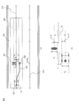
- region in the example of FIG. A diagram showing an example of an unmanned dump truck traveling in the adjacent lane
- each or all of the configurations, functions, processing units, processing means, and the like in the following embodiments may be realized as, for example, an integrated circuit or other hardware.
- each configuration, function, processing unit, processing unit, and the like, which will be described later may be realized as a program executed on a computer. That is, it may be realized as software.
- Information such as programs, tables, files, etc. for realizing each configuration, function, processing unit, processing means, etc. is stored in memory, hard disk, storage device such as SSD (Solid State Drive), storage medium such as IC card, SD card, DVD, etc. Can be stored.
- an obstacle avoidance system for avoiding an obstacle in front of the traveling lane by passing the adjacent lane and the adjacent lane of the host vehicle through the adjacent lane side of the obstacle will be described.
- the adjacent lane is an opposite lane
- the adjacent lane is a lane (parallel lane) that travels in the same direction as the host vehicle on a conveyance path including two or more lanes on one side.
- the traveling lane and the adjacent lane may be adjacent to each other, or may be installed apart from the two lanes.
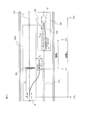
- FIG. 1 is a schematic diagram illustrating a configuration of an obstacle avoidance system.
- FIG. 2 is a block diagram showing a configuration of the control control device shown in FIG.
- FIG. 3 is a block diagram showing a configuration of the unmanned dump truck shown in FIG.
- FIG. 4 is a diagram illustrating an example of map information for the forward path and the return path in the first embodiment.
- the obstacle avoidance system 10 is configured by wirelessly connecting each of a host vehicle 12 and a manned vehicle 13 to a control control device 11.
- the control controller 11 manages the work content, travel position, and travel state of each of the own vehicle 12 and the manned vehicle 13 that perform work at a work site such as a mine. According to the work process at the work site, It plays a role of instructing the own vehicle 12 and the manned vehicle 13 to perform in the future.
- the control control device 11 includes four devices: a control control ECU (Electronic Control Unit) 20, a display device 61, an input device 62, and a communication device 81.
- the control control ECU 20, the display device 61, the input device 62, and the communication device 81 Each is configured to be electrically connected.
- the control control ECU 20 is an electronic control unit (ECU) having various functional means realized by a CPU (Central Processing Unit) executing a program stored in a memory. As shown in FIG. 2, the control control ECU 20 includes an IF control unit 21 that controls input / output of information between the display device 61 and the input device 62, a travel route and travel of the host vehicle 12 and the manned vehicle 13. A control database 22 for setting permission areas, travel conditions, etc., a communication control section 27 for controlling transmission / reception of wireless information to / from the communication device 81, and a map database storing information on travel routes and travel permission areas at work sites 28 (corresponding to a map information storage unit).
- ECU electronice control unit
- IF control unit 21 that controls input / output of information between the display device 61 and the input device 62, a travel route and travel of the host vehicle 12 and the manned vehicle 13.
- a control database 22 for setting permission areas, travel conditions, etc.
- a communication control section 27 for controlling transmission / reception of wireless information to
- the map information stored in the map database 28 includes a plurality of points (nodes) arranged along the traveling direction of each lane, and target tracks (lanes) defined by links connecting adjacent nodes. Center line) and width information along the vehicle width direction of the vehicle traveling on the basis of the target track is used. Details of the map information will be described later with reference to FIG.
- the control control unit 22 sets a travel route and a travel permission region for each of the own vehicle 12 and the manned vehicle 13 working at the mine site, so that the travel route setting unit 23 and the travel condition setting unit 24 are set.
- the travel permission area setting unit 25 and the departure possibility determination unit 26 are provided.
- the travel route setting unit 23 refers to the map information of the travel lane and the opposite lane (neighboring lane) of the host vehicle stored in the map database 28, and the current positions of the host vehicle 12 and the manned vehicle 13, A destination for each vehicle is determined and a travel route to reach the destination is set.
- the travel condition setting unit 24 determines the maximum speed of the vehicle on the travel route for each vehicle based on the speed limit and curvature for each lane defined in relation to the map information, the waiting time for the loading position, and the like. And driving conditions such as maximum acceleration.
- the travel permission area setting unit 25 refers to the map information of the travel lane, permits each vehicle to travel only in the vehicle, and prohibits other vehicles from entering the area. Set. That is, in the travel permission area setting unit 25, a partial area where the vehicle may travel is set as a travel permission area on the travel route set for each vehicle. Each vehicle can travel within a travel permission area (corresponding to the first travel permission area) set for the own vehicle, but it is not allowed to deviate from the travel permission area by the vehicle itself. Further, the other vehicle cannot enter the travel permission area set for the own vehicle, and the host vehicle cannot enter the travel permission area set for the other vehicle.
- the travel permission area setting unit 25 sets the first travel permission area to the length along the target track of the travel lane and the vehicle width direction centered on the target track. It is set using a two-dimensional area defined by the width of.
- the second lane permission area in which the other vehicle is permitted to travel only by the other vehicle with reference to the map information of the adjacent lane is set to the target of the adjacent lane. It is set using a two-dimensional region defined by the length along the track and the width in the vehicle width direction centering on the target track.
- the departure permission / inhibition determination unit 26 determines the position of the other vehicle and the travel permission region set for the other vehicle. Based on at least one of the positions of the (second travel permission area), it is determined whether or not the own vehicle is permitted to deviate from the first travel permission area.
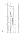
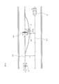
- FIG. 4 shows a scene in which the host vehicle 12 and the other vehicle 18 are traveling on a conveyance path composed of two lanes of an outward path and a return path at the mine site.
- the host vehicle 12 is traveling toward the right side in the plane of FIG. 4
- the other vehicle 18 is traveling toward the left side.
- the map information of each lane is defined using a target track composed of a plurality of nodes (white circles) arranged along the traveling direction, links connecting adjacent nodes, and left and right boundary lines of the target track.
- the target track 210 is configured using a node 211 and a link 212.
- the right boundary line 223 located on the right side in the traveling direction of the traveling lane is configured using the node 221 and the link 222, and the left boundary line 226 located on the left side in the traveling direction of the traveling lane is also composed of the node 224 and the link. 225.
- the right boundary line and the left boundary line are the lane boundary line on the right side of the target track in the direction of travel of the lane and the lane line on the left side.
- the boundary line is called the left boundary line.
- the map information of the oncoming lane is also configured using a target track 510 including a node 511 and a link 512, a right boundary line 523 configured using a node 521 and a link 522, a node 524 and a link 525 being left. Includes a boundary line 526.
- traveling permission areas 220 and 520 are set in the own vehicle 12 and the other vehicle 18, respectively.
- a safety margin distance ⁇ for avoiding interference between the host vehicle 12 and the other vehicle 18 is provided between the travel permission areas 220 and 520.
- symbol 300 shows the road shoulder installed in the both ends of a conveyance path.
- the travel route setting unit 23 sets a travel route for each vehicle by using a combination of all nodes 211 and links 212 or nodes 511 and links 512 from the current location to the destination.
- the control control unit 22 In the unlikely event that the vehicle 12 needs to deviate from the first travel permission area 220 in order to perform an obstacle avoidance operation while traveling, the control control unit 22 is requested to permit the departure.
- the control control unit 22, which is requested to permit the departure determines whether or not the departure from the first travel permission region 220 of the host vehicle 12 in the departure possibility determination unit 26 according to the setting state of the second travel permission region 520 of the other vehicle 18. Judge whether or not to deviate.
- a new first travel permission area of the host vehicle 12 is set by the travel permission area setting unit 25.
- the host vehicle 12 is allowed to travel to node (7) along a travel route represented by seven nodes from node (1) to node (7) in the first travel permission area 220. It will be. Before reaching node (7), the control control unit 22 is inquired whether the travel route after node (8) may be traveled, and the control control unit 22 sets the second travel permission area 520 of the other vehicle 18. Accordingly, the travel permission area of the host vehicle 12 is set for the travel route after node (8). By repeating this to the destination, the host vehicle 12 can travel safely to the destination without contacting the other vehicle 18.
- the display device 61 displays the travel permission area, travel route, travel speed, current travel position, and the like assigned to the host vehicle 12 and the manned vehicle 13 managed by the control control device 11 to the operator.
- an LCD liquid crystal display
- the input device 62 is a user interface through which an operator performs an input operation for giving an instruction to the control control device 11 such as switching contents to be displayed on the display device 61 or changing work contents for a specific vehicle.
- it is composed of a keyboard, a mouse, a touch panel, and a trackball.
- the communication device 81 receives information such as a travel position, a travel speed, and a vehicle state in order to manage the host vehicle 12 and the manned vehicle 13 by the control control device 11, and travels with respect to the host vehicle 12 and the manned vehicle 13. It is a device used for notifying travel instructions such as routes, travel conditions, and travel permission areas. Since work sites cover a wide area, wireless communication is generally used.
- a host vehicle 12 includes an obstacle detection sensor 40 (corresponding to an external sensor), a host vehicle position detection sensor 50, a vehicle control ECU 30, a communication device 82, and a vehicle control device 70.
- the control ECU 30, the obstacle detection sensor 40, the vehicle position detection sensor 50, the communication device 82, and the vehicle control device 70 are electrically connected to each other.
- the obstacle detection sensor 40 is a sensor for detecting an obstacle on the traveling path of the unmanned vehicle 12.
- the obstacle detection sensor 40 is configured using a sensor capable of detecting an obstacle that is an obstacle to the unmanned vehicle 12 traveling, such as a falling rock or uneven road surface, but is not managed by the control control device 11.
- a laser sensor or millimeter wave radar 41 (see FIG. 3) that detects the distance to the reflection target by measuring the time until the reflected light returns and irradiates the laser light.
- a stereo camera 42 (see FIG. 3) or the like that can identify the distance to the shooting target and the target based on the images of the two cameras that are set apart and shot at the same time may be used. However, sensors other than these may be used.
- the own vehicle position detection sensor 50 is a sensor used to detect vehicle movement information such as the position and posture of the own vehicle, the traveling speed, and the acceleration.
- vehicle movement information such as the position and posture of the own vehicle, the traveling speed, and the acceleration.
- a GPS receiver 51 capable of detecting the position and orientation of a vehicle by receiving radio waves transmitted from a plurality of GPS (Global Positioning System) satellites by an antenna 52, and a vehicle
- the gyro device 53 and the acceleration sensor 54 capable of detecting the angular velocity and acceleration of the vehicle, and the wheel speed sensor 55 capable of detecting the wheel rotational speed of the vehicle are included.
- the own vehicle position detection sensor 50 is not limited to the above example.
- the communication device 82 is a communication device for establishing a wireless communication connection between the host vehicle 12 and the control control device 11.
- the vehicle control device 70 includes a braking device 71 for decelerating and stopping the host vehicle 12, a steering device 72 that changes the steering angle, and a traveling device 73 that increases and decreases the fuel injection amount.
- the vehicle control ECU 30 is an electronic control unit (ECU) having various functional means realized by the CPU executing a program stored in the memory. As shown in FIG. 3, the vehicle control ECU 30 includes an obstacle detection unit 31, a vehicle position detection unit 32, a communication control unit 36, a map database 37, a vehicle control unit 33, an avoidance route generation unit 34, and a departure presence / absence determination unit 35. including.
- ECU electronice control unit
- the obstacle detection unit 31 is based on the output data of various types of obstacle detection sensors 40 mounted on the host vehicle 12, and the relative position and speed of the obstacles around the host vehicle 12 and the size of the obstacle in the vehicle width direction. Etc., and has a function of notifying the vehicle control unit 33 of necessary obstacle information.
- the own vehicle position detection unit 32 detects the position, posture, and speed of the own vehicle 12 based on the output data of the own vehicle position detection sensor 50 mounted on the own vehicle 12 and notifies the vehicle control unit 33 of these information. It has a function.
- the communication control unit 36 has a function of controlling mutual communication between the control control device 11 and the host vehicle 12 using the communication device 82.
- the map database 37 stores travel route information on the work site, travel conditions for the travel route notified from the control control device 11, and travel permission area information.
- the avoidance route generation unit 34 generates an avoidance route of the host vehicle for avoiding the obstacle. More specifically, a point where the own vehicle is displaced by the maximum amount of movement from the position of the obstacle toward the adjacent lane is determined as an avoidance point, and the distance between the avoidance point and the target track of the adjacent lane is determined by the distance of the own vehicle. When the vehicle width is larger than the vehicle width, an avoidance route for the host vehicle to pass the avoidance point is generated. Thereby, even when separating with an oncoming vehicle at an avoidance point, both interference can be prevented.
- the avoidance route generation unit 34 detects the own vehicle from the avoidance point when the obstacle detection sensor (external sensor) of the own vehicle does not detect a new obstacle different from the front obstacle while traveling on the avoidance route. A return route for returning to the target track of the traveling lane is further generated. Thereby, when there is no other obstacle ahead of the front obstacle, it can be returned, and the adjacent lane can be released earlier. Interference with another obstacle can be avoided.
- the avoidance route generation unit 34 curvatures of the avoidance route and the return route so that the lateral acceleration applied to the host vehicle traveling on the avoidance route is equal to or less than a reference lateral acceleration provided to suppress the rollover of the own vehicle. May be determined. Thereby, even during the obstacle avoidance / return operation, the host vehicle can be driven more safely without performing steering control at a steep angle.
- Departure presence / absence determination unit 35 determines whether or not to depart from the first travel permission area when the host vehicle travels along the avoidance route. If the vehicle does not deviate, the avoidance operation within the first travel permission area is possible, so there is no influence on the oncoming lane and the host vehicle can perform the avoidance operation. When deviating, it is possible to determine whether or not an avoidance operation is possible by considering the influence on the oncoming lane.
- the vehicle control unit 33 moves the host vehicle 12 on the travel route based on the travel conditions, the travel route, the travel permission area, and the own vehicle position information notified from the own vehicle position detection unit 32 instructed from the control control device 11.
- the vehicle control device 70 has a function of giving a control command so that the vehicle travels in accordance with the travel conditions within the travel permission section set to. Thereby, the own vehicle 12 autonomously travels to the destination.
- the vehicle control unit 33 determines the maximum movement amount in the vehicle width direction of the host vehicle to avoid the obstacle based on the relative position of the obstacle, the size of the obstacle in the vehicle width direction, and the vehicle width of the host vehicle. It has a function as a movement amount calculation unit to calculate. Details of this will be described later.
- the manned vehicle 13 includes a display device 63, an input device 64, a vehicle position detection sensor 65, a communication device 83, and a navigation ECU 90.
- the navigation ECU 90, the display device 63, the input device 64, and the vehicle The position detection sensor 65 and the communication device 83 are electrically connected to each other.
- the own vehicle position detection sensor 65 is used to detect the travel position, posture, and speed of the manned vehicle 13, and a GPS receiver or the like may be used similarly to the sensor mounted on the own vehicle 12.
- the display device 63 displays the travel route, the travel permission area, and the position of the host vehicle, which are instructed from the control control device 11, on a display screen including an LCD, for example. Thereby, it is possible to confirm which position on the mine site the driver of the manned vehicle 13 is currently traveling.
- the input device 64 is used for an instruction to switch the display screen of the display device 63 and for the driver to obtain permission to deviate from the travel permission area to the control control device 11.
- the communication device 83 performs control related to wireless communication between the manned dump 13 and the control control device 11.
- the navigation ECU 90 is a manned vehicle based on the travel permission area obtained via the communication device 83, the vehicle position information output from the vehicle position detection sensor 65, and the travel route information stored in the navigation ECU 90. 13 has a function of calculating which position the vehicle is traveling with respect to the travel route and the travel permission area. If it is determined that the vehicle position may deviate from the travel permission area, the navigation ECU 90 may notify the driver that the vehicle position may deviate from the travel permission area. An alarm may be issued when the permitted area is deviated.
- FIG. 5 is a flowchart showing the flow of the obstacle avoidance process.
- FIG. 6 is a flowchart showing the flow of the determination process of whether or not the travel permitted area departs in step S510 in FIG.
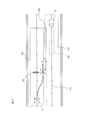
- FIG. 7 is a diagram illustrating an example in which an obstacle exists outside the unmanned dump traveling area.
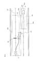
- FIG. 8 is a diagram showing an example in which an obstacle exists in the traveling area of the unmanned dump and can be avoided in the travel permission area, where (a) is an overall view, and (b) is an enlarged view around the vehicle. It is.
- FIG. 5 is a flowchart showing the flow of the obstacle avoidance process.
- FIG. 6 is a flowchart showing the flow of the determination process of whether or not the travel permitted area departs in step S510 in FIG.
- FIG. 7 is a diagram illustrating an example in which an obstacle exists outside the unmanned dump traveling area.
- FIG. 8 is a diagram showing an example in which an obstacle exists in the traveling area of the unmanned dump and can be avoided in
- FIG. 9 is a diagram illustrating a state in which a route that returns to the travel route after the obstacle avoiding operation in the example of FIG. 8 is generated.
- FIG. 10 is a diagram illustrating an example in which an obstacle exists in the traveling area of the unmanned dump and must deviate from the travel permission area.
- FIG. 11 is a diagram showing the update of the travel permission area in the example of FIG.
- FIG. 12 is a diagram illustrating a case where an unmanned dump truck traveling in the adjacent lane exists.
- FIG. 13 is a diagram illustrating the update of the travel permission area in the example of FIG. FIG.
- FIG. 14 is a diagram illustrating an example in which there is an unmanned dump truck traveling in the adjacent lane, and when the travel permission area is changed to avoid an obstacle, the unattended dump traveling in the adjacent lane overlaps with the traveling area.
- description will be made along the order of steps in FIG.
- step S501 the obstacle detection unit 31 acquires obstacle detection information (S501).
- the obstacle detection sensor 40 generates detection data within the detection range 150 and outputs the detection data to the obstacle detection unit 31.
- the obstacle detection unit 31 detects the obstacle 400 in the detection range 150 based on the detection data, and outputs the detection result of the obstacle 400 to the vehicle control unit 33.
- the vehicle control unit 33 detects the relative distance (Xo, Yo) and the size Wo from the host vehicle 12 made of an unmanned dump truck.
- the relative distance (Xo, Yo) is a vehicle width direction perpendicular to the vehicle traveling direction, with the vehicle traveling direction as the X-axis, with the origin as a point perpendicular to the traveling route from the center position of the rear axle of the host vehicle 12 Is a coordinate system along the travel route with Y as the axis.
- step S ⁇ b> 502 the vehicle control unit 33 determines whether or not the detected obstacle 400 exists within the traveling region of the host vehicle 12.
- the travel region is a region 230 having a width in the vehicle width direction along the vehicle travel direction, which is ahead of the current position of the host vehicle 12 in the travel permission region 220. Is set to a length equivalent to the vehicle width Wm of the host vehicle 12 (W ⁇ Wm).
- a determination formula as to whether an obstacle exists in the traveling region 230 is expressed by the following formula.
- the vehicle 12 does not interfere with the obstacle 400 even if the vehicle 12 continues to travel in the travel area 230, so the process returns to step S501 and continues autonomously. Continue to detect obstacles.
- the obstacle 400 exists in the traveling region 230 (S502 / YES), for example, when the host vehicle 12 does not satisfy the above formula (1) as in the positional relationship between the obstacle 401 and the host vehicle 12 shown in FIG. If the vehicle continues to travel in the traveling area 230, it will interfere with the obstacle 400. Then, it progresses to step S503 and the avoidance operation
- step S503 the avoidance route generation unit 34 installed in the vehicle control ECU 30 calculates a lateral movement amount for avoiding an obstacle (S503).
- the avoidance route generation process will be described with reference to FIG.
- the avoidance route generation unit 34 calculates a lateral movement amount D (see FIG. 8A) that the host vehicle 12 must move laterally with respect to the travel route in order to avoid an obstacle.
- D lateral movement amount
- the clearance distance between the host vehicle 12 and the obstacle 401 when approaching the obstacle 401 is ⁇ , the following equation ( The vehicle must travel at a position separated by a distance Dt shown in 2) (see FIG. 8B).
- an avoidance position 250 a position adjacent to an obstacle that must be passed when the obstacle 401 is avoided is referred to as an avoidance position 250.
- the lateral movement amount D from the current position of the host vehicle 12 along the Y-axis direction is the maximum movement amount.
- the lateral movement amount D with respect to the travel route is calculated by the following equation (3).
- the vehicle control unit 33 moves the vehicle 12 through the travel permission area 220 when the vehicle 12 moves by the lateral movement amount D calculated by the equation (3) and passes the avoidance position 250. Whether or not to deviate is determined based on the following equation (4).
- the lateral width of the travel permission area at the avoidance position 250 is set to W1 and Wr on the left and right with respect to the travel route.
- Formula (4) is a judgment formula when avoiding on the right side with respect to the travel route
- Formula (5) is a judgment formula when avoiding on the left side.
- Step S505 When Formula (4) or Formula (5) is satisfied, that is, it is determined that the host vehicle 12 does not depart from the travel permission region 220 (S504 / No), and the process proceeds to Step S505 to execute an obstacle avoidance operation.
- the positional relationship between the dump 12 and the obstacle 401 shown in FIG. 8 transitions from step S504 to step S505 because Expression (4) is established.
- step S505 the vehicle control unit 33 steers the steering device 72 of the vehicle control device 70 in order to avoid the obstacle 401 based on the lateral movement amount D calculated by the avoidance route generation unit 34 in step S503. Control is performed (S505).
- the steering control method calculates a clothoid curve connecting a point 255 on the target trajectory at the current position of the unmanned dump truck 12 and the avoidance position 250, and steers the vehicle so as to travel along the clothoid curve. Control is sufficient. However, the present invention is not limited to this method, and other steering control methods may be used.
- step S506 if the vehicle control unit 33 determines that there is no obstacle on the traveling route of the vehicle, a return route to return to the traveling route is generated (S506).
- the return route may be generated by the same method as in step S505 by generating a route for moving the host vehicle 12 to the target track side by the lateral movement amount D.
- FIG. 9 shows the processing of this step.
- the host vehicle 12 located at the avoidance position 250 monitors the front obstacle in the vehicle traveling direction by the obstacle detection sensor 40.
- the host vehicle 120 may generate a return path based on the lateral movement amount D or the steering amount in step S505 immediately before passing the avoidance position 250, or the clothoid curve calculated in step S505. May be reversed about the vehicle traveling direction axis to generate the return path 270.
- the vehicle control unit 33 performs steering control so as to travel along the return route generated in step S506, and returns the host vehicle 12 to the target track 210 of the travel lane (S507).
- the obstacle avoidance / return operation in the travel permission area shown in FIGS. 8 and 9 is completed.
- step S508 the vehicle control unit 33 calculates the amount of departure from the travel permission area 220 by the following formulas (6) and (7) (S508).
- step S509 the vehicle control unit 33 refers to the map information stored in the map database 28, and checks whether there is a neighboring lane in the departure direction of the travel permission area 220. This is a judgment condition that assumes the case where the travel route is a single lane. In the case of a single lane, there is a risk of falling from the cliff or hitting the earth when deviating from the travel permission region. Without making a transition to step S613.
- the departure possibility determination unit 26 of the control control device 11 determines whether the host vehicle 12 may depart from the travel region 220 (S510). With reference to FIG. 6, the travel permission area deviation permission determination process executed in this step will be described.
- departure permission determination unit 26 determines whether or not departure is possible in the order of steps shown in FIG.
- step S601 the departure possibility determination unit 26 determines whether a travel permission area for another vehicle is set in the adjacent lane. If the result is affirmative (S601 / Yes), the vehicle traveling in the adjacent lane is an unmanned dump. It is determined whether or not (S602).
- step S602 when the vehicle traveling in the adjacent lane is a manned vehicle (S602 / No), the unmanned vehicle 12 is prohibited from deviating from the travel permitted area 220 (S606). Since the manned vehicle is equipped with a display device 63 for displaying the positional relationship between the travel permission area and the own vehicle to the driver, it is possible to notify that the own vehicle 12 approaches the manned vehicle. However, as a safety measure when the driver is not aware of the notification, the host vehicle 12 is stopped (S606 to S511, S517).
- the departure possibility determination unit 26 determines that the travel permission area of the other vehicle is not set in the adjacent lane (S601 / No; see FIG. 10), or the own vehicle does not enter the travel area of the other vehicle (S603). / No), it determines with the own vehicle deviating from a driving
- the departure possibility determination unit 26 avoids the own vehicle in the travel permission area of the other vehicle. If there is no avoidance area to perform, or even if there is an avoidance area, the avoidance action is not in time (S604 / No), it is determined that departure is not possible (S606).
- the travel permission region setting unit 25 sets the travel permission region 220 in accordance with the deviation amount Dd from the travel permission region 220.
- the shape is changed, and the vehicle in which the travel permission area 220 is set is notified of the change in the shape of the travel permission area (S512).
- the travel permission area setting unit 25 extends the width of the travel permission area 220 to a width that includes the host vehicle 12 traveling on the avoidance route.
- the travel permission area setting unit 25 sets the width of the travel permission area 220 to the width of the self-traveling avoidance route. While expanding to a width that encompasses the vehicle, the travel permission area width 520 of the other vehicle 18 is reduced so as not to overlap the expanded first travel area.
- the communication device 81 of the control control device 11 transmits information indicating the change content to the communication device 82 of the host vehicle 12 to transmit the vehicle. Input to the control unit ECU 30.
- the host vehicle 12 executes an obstacle avoidance operation (S513), generates a return path for returning to the target track (S514), and performs a return operation to the target track, as in steps S505 to S507.
- an obstacle avoidance operation S513
- the obstacle avoidance operation is completed, and the process proceeds to step S516.
- step S 516 the control controller 11 is notified that the host vehicle 12 has returned to the target track via the communication device 82.
- the travel permission area setting unit 25 narrows the width of the travel permission area 220 and restores the original state. Further, when the width of the travel permission area 520 of the other vehicle 18 is reduced, this is expanded and the original state is restored.
- the control control device 11 notifies the host vehicle 12 again that the shape of the travel permission area 220 has been restored to its original shape (S516), and completes all avoidance sequences.
- the travel permission area setting unit 25 increases the right width Wr with respect to the target track of the travel permission area 220 by an amount corresponding to the deviation amount Dd (the right boundary line 223 of the travel permission area 220 in FIG. 11 is shifted to 223a). )
- control is performed so that the vehicle 12 does not depart from the new travel permission section 220 set for the vehicle. Since other vehicles do not enter the travel permission section 220 assigned to the host vehicle (blocking control), the host vehicle 12 can travel safely without interfering with the other vehicle during the avoidance operation of the obstacle 402. I can do it.
- FIG. 12 shows a state in which an obstacle cannot be avoided unless the own vehicle 12 departs from the currently set travelable area.
- the width of the travelable area 220 being set is expanded in accordance with the deviation amount Dd, an area 285 that overlaps the currently set travelable area 520 is generated on the other vehicle 18 traveling in the adjacent lane. It does not enter the traveling area 530 of the other vehicle 18. Therefore, in step S603 of FIG. 6, it is determined as “No” in the determination of “Does the host vehicle enter the traveling area of the other vehicle?” And it is determined that the vehicle can deviate (S605).
- the travel permission area setting unit 25 increases the width of the travel permission area 220 according to the deviation amount Dd of the host vehicle 12 from the travel permission area 220 (the right boundary of the travel permission area 220).
- the line 223 is shifted to 223a) and the width of the travel permission area 221 is reduced (the right boundary line 523 of the travel permission area 520 is shifted to 523a) (S612).
- the width of the travel permission area 220 is expanded to the travel permission area 220a, and the width of the travel permission area 520 is contracted to the travel permission area 520a.
- there is no overlapping area between the travel permission area 220a and the travel permission area 520a and the unmanned dump trucks 12 and 18 do not interfere with each other.
- step S603 it is determined that the host vehicle enters the entry area of another vehicle (S603 / Yes), and the process proceeds to step S604.
- the other vehicle 18 avoids the overlap area 290, it is determined whether or not the vehicle 12 deviates from the travel permission area 520 of the other vehicle 18, and when the own vehicle 12 avoids the obstacle 403 based on the lateral movement amount D. Then, it is determined whether or not a sufficient interval L between the host vehicle 12 and the other vehicle 18 is secured. If the overlap area 290 has a width Dlap and the amount of lateral movement that the other vehicle 18 must move to avoid the overlap area 290 is D1, the travel permission is permitted when the other vehicle 18 avoids the overlap area 290. Whether or not to deviate from the area 520 can be determined by Expression (5).
- Whether or not the interval L is sufficiently secured may be determined, for example, by evaluating in advance the braking avoidance limit distance Lth with respect to the traveling speed of the unmanned dump and determining whether L> Lth.
- the process proceeds to step S605, and the departure possibility determination unit 26 determines that the host vehicle 12 may depart from the travel permission area 220 and avoid the obstacle 403.
- the subsequent processing is the same as in FIG. 13 except that the other vehicle 18 moves laterally by the lateral movement amount D1 in step S513.
- the control controller is notified in step S516 that the return to the travel route is completed, the travel permission areas for both unmanned dump trucks are restored.
- the return to the original travel route is executed from the state in which the other vehicle 18 has moved laterally by the lateral movement amount D1.
- all avoidance sequences are completed.
- the own vehicle since the distance between the avoidance point and the center line of the adjacent lane is made wider than the vehicle width of the own vehicle, when avoiding an obstacle, the own vehicle separates from the same type of other vehicle at the avoidance point. Even if it does not interfere with other vehicles.
- the width of the travel permission area of the own vehicle is increased, the travel permission area width of the other vehicle is decreased, By causing the other vehicle to perform the avoidance operation, the obstacle avoidance operation using the adjacent lane can be performed while reducing the influence of the adjacent lane on the traveling state of the vehicle.
- map information of the transport path is generated as one-dimensional information using only nodes and links, and the distance d between the target track, the avoidance route, and the target track of the adjacent lane is compared.
- This is an embodiment for performing an obstacle avoidance operation based on the result.
- the difference from the first embodiment is that the map information is not two-dimensional information but one-dimensional information, and the other components and the flow of processing are the same, and therefore a duplicate description is omitted.
- generation of an avoidance route according to the second embodiment will be described with reference to FIG.
- FIG. 15 is a diagram illustrating an example of a positional relationship between the host vehicle and the adjacent lane according to the second embodiment.
- the map information of the second embodiment is defined using a one-dimensional target trajectory defined from a plurality of nodes along the traveling direction of each lane and links connecting adjacent nodes.
- the travel permission area is defined by a one-dimensional area composed of a partial area of the target track.
- generation part 34 produces
- the obstacle avoidance operation using the adjacent lane can be performed safely without performing processing such as changing the width of the travel permission area.
- the avoidance route generation unit 34 and the deviation presence / absence determination unit 35 in the vehicle control ECU 30 mounted on the host vehicle 12 may be stored in the control control ECU 20 in the control control device 11.
- obstacle detection information and travel information necessary for realizing the functions of the avoidance route generation unit 34 and the deviation presence / absence determination unit 35 may be periodically notified from the own vehicle 12 to the control control device 11.
- the control control device 11 manages the state of the mine site traveling path, the vehicle detection information such as the position and size of the obstacle determined by the host vehicle 12 to be avoided is sent to the control control device 11. You may be notified. By notifying the control control device 11, the maintenance activities at the mine site can be made more efficient.
- the control control ECU 20 of the control control device 11 includes an obstacle information storage unit 29 b that stores obstacle information on the traveling road, and the control control device 11 has the function of the avoidance route generation unit 34.
- the avoidance route may be generated, and the travel permission region setting unit 25 may set the travel permission region on the avoidance route with reference to the obstacle information.
- the detection result of the obstacle detection unit 31 is acquired and compared with the obstacle information stored in the obstacle information storage unit 29b, and the detection result of the obstacle detection unit 31 is not included in the obstacle information.
- an obstacle information management unit 29a that adds the detection result of the obstacle detection unit 31 to the obstacle information storage unit 29b may be further provided.
Abstract
Description
図1乃至図4を参照して、本実施形態に係る障害物回避システム10の概略構成について説明する。図1は、障害物回避システムの構成を示す概略図である。図2は、図1に示す管制制御装置の構成を示すブロック図である。図3は、図1に示す無人ダンプの構成を示すブロック図である。図4は、第一実施形態における往路及び復路の地図情報例を示す図である。


第二実施形態は、搬送路(往路及び復路)の地図情報をノード及びリンクのみを用いて1次元情報として生成し、目標軌道、回避経路、及び隣車線の目標軌道の間の距離dの比較結果に基づき、障害物の回避動作を行う実施形態である。第一実施形態との違いは、地図情報が2次元情報ではなく1次元情報である点であり、その他の構成要素、処理の流れは同一であるので、重複説明は省略する。以下、図15を参照して、第二実施形態に係る回避経路の生成について説明する。図15は、第二実施形態に係る自車両と隣車線との位置関係の一例を示す図である。
Claims (9)
- 自車両の走行車線及び隣車線が並んで配置され、前記走行車線の前方にある障害物を、当該障害物の前記隣車線側を通過して回避するための障害物回避システムであって、
前記自車両に搭載された外界センサからの出力に基づいて、前記自車両を基準とする前記障害物の相対位置、及び前記障害物の車幅方向の大きさを検出する障害物検出部と、
前記障害物を回避するための前記自車両の車幅方向の最大移動量を、前記障害物の相対位置、前記障害物の車幅方向の大きさ、及び前記自車両の車幅に基づいて算出する移動量算出部と、
前記障害物の位置から前記隣車線側に向かって前記最大移動量変位した地点を回避地点として求め、当該回避地点と前記隣車線の中心線との間の距離が前記自車両の車両幅よりも大きい場合に、前記自車両が前記回避地点を通過するための回避経路を生成する回避経路生成部と、
を備えることを特徴とする障害物回避システム。 - 請求項1記載の障害物回避システムにおいて、
前記走行車線及び前記隣車線のそれぞれについて、走行方向に沿った複数のノード、及び隣接するノードを接続するリンクから定義される目標軌道、及び当該目標軌道を中心とし車幅方向の幅情報を用いて定義した地図情報を記憶する地図情報記憶部と、
前記走行車線の地図情報を参照し、前記自車両に対して、当該自車両のみの走行を許可する第一走行許可領域を、前記走行車線の目標軌道に沿った長さ、及び前記目標軌道を中心とする車幅方向の幅により定義された2次元領域を用いて設定するとともに、前記隣車線を他車両が走行する際に、前記隣車線の地図情報を参照して、前記他車両に対して、当該他車両のみの走行を許可する第二走行許可領域を、前記隣車線の目標軌道に沿った長さ、及び前記目標軌道を中心とする車幅方向の幅により定義された2次元領域を用いて設定する走行許可領域設定部と、
前記回避経路に沿って前記自車両が走行した場合に、前記第一走行許可領域から逸脱をするかを判定する逸脱有無判定部と、
前記自車両が前記第一走行許可領域から逸脱すると判定された際に、前記他車両の位置、及び前記第二走行許可領域の位置の少なくとも一つに基づいて、前記自車両が前記第一走行許可領域から逸脱することを許容するかを判定する逸脱可否判定部と、を更に備え、
前記逸脱可否判定部が前記逸脱を許容する場合に、前記走行許可領域設定部は、前記第一走行許可領域幅を、前記回避経路を走行中の自車両を包含する幅に拡張する、
ことを特徴とする障害物回避システム。 - 請求項2に記載の障害物回避システムにおいて、
前記第一走行許可領域幅を拡張すると、前記第二走行許可領域に重なる領域が生じる場合、前記走行許可領域設定部は、前記第一走行許可領域幅を、前記回避経路を走行中の自車両を包含する幅に拡張するとともに、前記第二走行許可領域幅を前記拡張後の第一走行領域と重ならないように縮小する、
ことを特徴とする障害物回避システム。 - 請求項3記載の障害物回避システムにおいて、
前記自車両の前記外界センサが前記回避経路を走行中に、前記前方障害物とは異なる新たな障害物を検知しない場合に、前記回避経路生成部は、前記自車両を前記回避地点から前記走行車線の目標軌道に復帰させるための復帰経路を更に生成する、
ことを特徴とする障害物回避システム。 - 請求項4記載の障害物回避システムにおいて、
前記回避経路生成部は、前記回避経路及び復帰経路を走行中の前記自車両に加わる横加速度が、前記自車両の横転を抑止するために設けられた基準横加速度以下になるように前記回避経路及び復帰経路の曲率を定める、
ことを特徴とする障害物回避システム。 - 請求項5記載の障害物回避システムにおいて、
前記自車両が前記復帰経路を走行して前記走行車線の目標軌道に復帰すると、前記走行許可領域管理部は、前記拡張した第一走行許可領域の幅を拡張前の幅に縮小し、前記縮小した第二走行許可領域の幅を縮小前の幅に拡張する、
ことを特徴とする障害物回避システム。 - 請求項1記載の障害物回避システムにおいて、
前記走行車線上における前記障害物の位置及び前記障害物の車幅方向の大きさを示す障害物情報を記憶する障害物情報記憶部を更に備え、
前記回避経路生成部は、前記障害物情報を参照して、前記回避経路を生成する、
ことを特徴とする障害物回避システム。 - 請求項7記載の障害物回避システムにおいて、
前記障害物検出部の検出結果を取得して、前記障害物情報記憶部に記憶された障害物情報と比較し、当該障害物情報に、前記取得した前記障害物検出部の検出結果が含まれていない場合に、前記障害物情報記憶部に前記障害物検出部の検出結果を追加する障害物情報管理部を更に備える、
ことを特徴とする障害物回避システム。 - 請求項1記載の障害物回避システムにおいて、
前記複数の車線のそれぞれの地図情報を格納する地図情報格納部と、
前記各車両に対して、自車両が走行する走行車線の一部領域を、当該自車両のみの走行を許可する走行許可領域として設定する走行許可領域設定部と、を更に備え、
前記地図情報は、前記各車線の走行方向に沿った複数のノード、及び隣接するノードを接続するリンクから定義される目標軌道を用いて定義され、
前記走行許可領域は、前記目標軌道の部分領域からなる1次元領域により定義され、
前記回避経路生成部は、前記回避地点から前記隣車線の目標軌道までの距離が前記自車両の車両幅よりも大きい場合に、前記回避経路を生成する、
ことを特徴とする障害物回避システム。
Priority Applications (3)
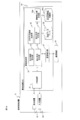
| Application Number | Priority Date | Filing Date | Title |
|---|---|---|---|
| CA2957627A CA2957627C (en) | 2014-09-29 | 2015-03-06 | Obstacle avoidance system |
| US15/502,299 US10255811B2 (en) | 2014-09-29 | 2015-03-06 | Obstacle avoidance system |
| AU2015326186A AU2015326186B2 (en) | 2014-09-29 | 2015-03-06 | Obstacle avoidance system |
Applications Claiming Priority (2)
| Application Number | Priority Date | Filing Date | Title |
|---|---|---|---|
| JP2014-199463 | 2014-09-29 | ||
| JP2014199463A JP6280850B2 (ja) | 2014-09-29 | 2014-09-29 | 障害物回避システム |
Publications (1)
| Publication Number | Publication Date |
|---|---|
| WO2016051818A1 true WO2016051818A1 (ja) | 2016-04-07 |
Family
ID=55629878
Family Applications (1)
| Application Number | Title | Priority Date | Filing Date |
|---|---|---|---|
| PCT/JP2015/056702 WO2016051818A1 (ja) | 2014-09-29 | 2015-03-06 | 障害物回避システム |
Country Status (5)
| Country | Link |
|---|---|
| US (1) | US10255811B2 (ja) |
| JP (1) | JP6280850B2 (ja) |
| AU (1) | AU2015326186B2 (ja) |
| CA (1) | CA2957627C (ja) |
| WO (1) | WO2016051818A1 (ja) |
Cited By (7)
| Publication number | Priority date | Publication date | Assignee | Title |
|---|---|---|---|---|
| WO2016203796A1 (ja) * | 2015-06-17 | 2016-12-22 | 日立建機株式会社 | 管制制御システム、管制制御装置、及び車載端末装置 |
| JP2017211734A (ja) * | 2016-05-24 | 2017-11-30 | ヤンマー株式会社 | 自律走行経路生成システム |
| CN108454625A (zh) * | 2017-02-17 | 2018-08-28 | 通用汽车环球科技运作有限责任公司 | 用于预测并防止当自主或半自主驾驶车辆时的可能车道偏离的系统和方法 |
| CN111273662A (zh) * | 2020-02-05 | 2020-06-12 | 北京百度网讯科技有限公司 | 车辆控制方法、装置、电子设备及可读存储介质 |
| JP2020109693A (ja) * | 2020-03-25 | 2020-07-16 | ヤンマーパワーテクノロジー株式会社 | 自律走行経路生成システム |
| WO2020179386A1 (ja) * | 2019-03-04 | 2020-09-10 | パナソニックIpマネジメント株式会社 | 移動体制御方法、移動体制御システム、及びプログラム |
| US10775805B2 (en) | 2016-08-26 | 2020-09-15 | Crown Equipment Limited | Materials handling vehicle path validation and dynamic path modification |
Families Citing this family (94)
| Publication number | Priority date | Publication date | Assignee | Title |
|---|---|---|---|---|
| US10431099B2 (en) * | 2014-02-21 | 2019-10-01 | FLIR Belgium BVBA | Collision avoidance systems and methods |
| JP2016081403A (ja) * | 2014-10-21 | 2016-05-16 | 株式会社Ihiエアロスペース | 無人移動体とその経路生成方法 |
| DE102015202099A1 (de) * | 2015-02-06 | 2016-08-11 | Bayerische Motoren Werke Aktiengesellschaft | Verarbeiten von Sensordaten für ein Fahrerassistenzsystem |
| JP6376055B2 (ja) * | 2015-06-26 | 2018-08-22 | 株式会社デンソー | 車線逸脱抑制システム |
| JP6657618B2 (ja) * | 2015-06-30 | 2020-03-04 | 株式会社デンソー | 逸脱回避装置 |
| DE102016009764A1 (de) * | 2016-08-11 | 2018-02-15 | Trw Automotive Gmbh | Steuerungssystem und Steuerungsverfahren zum Führen eines Kraftfahrzeugs entlang eines Pfades und zum Vermeiden einer Kollision mit einem anderen Kraftfahrzeug |
| US10480157B2 (en) * | 2016-09-07 | 2019-11-19 | Caterpillar Inc. | Control system for a machine |
| JP6599835B2 (ja) * | 2016-09-23 | 2019-10-30 | 日立建機株式会社 | 鉱山用作業機械、障害物判別装置、及び障害物判別方法 |
| JP2018106473A (ja) * | 2016-12-27 | 2018-07-05 | パイオニア株式会社 | 車両制御装置、車両制御方法及びプログラム |
| RU2734744C1 (ru) | 2017-02-10 | 2020-10-22 | Ниссан Норт Америка, Инк. | Оперативное управление автономным транспортным средством, включающее в себя работу экземпляра модели частично наблюдаемого марковского процесса принятия решений |
| MX2019009395A (es) | 2017-02-10 | 2019-12-05 | Nissan North America Inc | Monitoreo del bloqueo de la administracion operacional de vehiculos autonomos. |
| EP3580620B1 (en) * | 2017-02-10 | 2023-09-06 | Nissan North America, Inc. | Autonomous vehicle operational management control |
| JP2018136700A (ja) * | 2017-02-21 | 2018-08-30 | トヨタ自動車株式会社 | 車両の制御装置 |
| US11320825B2 (en) | 2017-03-30 | 2022-05-03 | Nec Corporation | Vehicle control system, self-driving vehicle, vehicle control method, and program |
| US11150662B2 (en) | 2017-03-30 | 2021-10-19 | Nec Corporation | Vehicle control system, self-driving vehicle, vehicle control method, and program |
| US10725470B2 (en) * | 2017-06-13 | 2020-07-28 | GM Global Technology Operations LLC | Autonomous vehicle driving systems and methods for critical conditions |
| JP6962027B2 (ja) * | 2017-06-23 | 2021-11-05 | 株式会社豊田自動織機 | 移動車両 |
| JP6926723B2 (ja) * | 2017-06-27 | 2021-08-25 | いすゞ自動車株式会社 | 車速制御装置 |
| US20190061765A1 (en) * | 2017-08-23 | 2019-02-28 | Uber Technologies, Inc. | Systems and Methods for Performing Lane Changes Around Obstacles |
| CN108001444B (zh) * | 2017-10-11 | 2019-10-22 | 北京车和家信息技术有限公司 | 自动驾驶车辆控制方法及系统 |
| JP2019079255A (ja) * | 2017-10-24 | 2019-05-23 | 清水建設株式会社 | 情報通信システム、情報発信装置、および情報受信装置 |
| WO2019088977A1 (en) | 2017-10-30 | 2019-05-09 | Nissan North America, Inc. | Continual planning and metareasoning for controlling an autonomous vehicle |
| WO2019089015A1 (en) | 2017-10-31 | 2019-05-09 | Nissan North America, Inc. | Autonomous vehicle operation with explicit occlusion reasoning |
| US11027751B2 (en) | 2017-10-31 | 2021-06-08 | Nissan North America, Inc. | Reinforcement and model learning for vehicle operation |
| WO2019108213A1 (en) | 2017-11-30 | 2019-06-06 | Nissan North America, Inc. | Autonomous vehicle operational management scenarios |
| US11874120B2 (en) | 2017-12-22 | 2024-01-16 | Nissan North America, Inc. | Shared autonomous vehicle operational management |
| US10585434B2 (en) * | 2018-01-10 | 2020-03-10 | GM Global Technology Operations LLC | Relaxable turn boundaries for autonomous vehicles |
| JP7020130B2 (ja) * | 2018-01-17 | 2022-02-16 | トヨタ自動車株式会社 | 車両制御装置、方法、およびプログラム |
| CN111902782A (zh) | 2018-02-26 | 2020-11-06 | 北美日产公司 | 集中式共享自主运载工具操作管理 |
| DE102018202970A1 (de) * | 2018-02-28 | 2019-08-29 | Robert Bosch Gmbh | Verfahren zum Ermitteln einer topologischen Information einer Straßenkreuzung |
| US10775494B2 (en) * | 2018-03-07 | 2020-09-15 | Aptiv Technologies Limited | Method and system for determining the pointing angle of a moving object |
| JP2019166870A (ja) * | 2018-03-22 | 2019-10-03 | 株式会社Soken | 車両走行制御装置、車両走行制御システムおよび車両走行制御方法 |
| JP6945486B2 (ja) * | 2018-04-16 | 2021-10-06 | 三菱電機株式会社 | 通知情報生成装置及び通知情報生成プログラム |
| CN110621541B (zh) * | 2018-04-18 | 2023-03-28 | 百度时代网络技术(北京)有限公司 | 用于生成轨迹以操作自动驾驶车辆的方法和系统 |
| US10614717B2 (en) * | 2018-05-17 | 2020-04-07 | Zoox, Inc. | Drive envelope determination |
| US11120688B2 (en) | 2018-06-29 | 2021-09-14 | Nissan North America, Inc. | Orientation-adjust actions for autonomous vehicle operational management |
| WO2020025991A1 (ja) * | 2018-08-03 | 2020-02-06 | 日産自動車株式会社 | 走行軌跡補正方法、走行制御方法、及び走行軌跡補正装置 |
| US10496100B1 (en) * | 2018-09-11 | 2019-12-03 | Universal City Studios Llc | Ultraviolet paint-based vehicle guidance |
| CN111712417B (zh) * | 2018-09-28 | 2023-09-01 | 百度时代网络技术(北京)有限公司 | 用于自动驾驶车辆的、基于隧道的规划系统 |
| JP2020066300A (ja) * | 2018-10-23 | 2020-04-30 | トヨタ自動車株式会社 | 車両制御装置 |
| US11827241B2 (en) * | 2018-10-29 | 2023-11-28 | Motional Ad Llc | Adjusting lateral clearance for a vehicle using a multi-dimensional envelope |
| JP6935507B2 (ja) * | 2018-12-26 | 2021-09-15 | バイドゥ ドットコム タイムス テクノロジー (ベイジン) カンパニー リミテッド | 自動運転のための自己反転線の相互回避アルゴリズム |
| EP3889722A4 (en) * | 2018-12-29 | 2022-02-09 | Great Wall Motor Company Limited | METHOD AND SYSTEM FOR GENERATING A DYNAMIC TARGET LINE DURING AUTOMATIC DRIVING OF A VEHICLE, AND VEHICLE |
| CN109887056B (zh) * | 2019-01-11 | 2023-01-03 | 安徽宏途机器人科技有限公司 | 基于cad的移动设备所处场地内障碍物检测系统及方法 |
| CN109733392B (zh) * | 2019-01-30 | 2021-01-19 | 浙江吉利汽车研究院有限公司 | 一种避障方法及装置 |
| CN109871787B (zh) * | 2019-01-30 | 2021-05-25 | 浙江吉利汽车研究院有限公司 | 一种障碍物检测方法及装置 |
| US11142196B2 (en) * | 2019-02-03 | 2021-10-12 | Denso International America, Inc. | Lane detection method and system for a vehicle |
| JP7254432B2 (ja) * | 2019-02-14 | 2023-04-10 | 三菱電機株式会社 | 運転支援装置および運転支援方法 |
| DE102019105547A1 (de) * | 2019-03-05 | 2020-09-10 | Bayerische Motoren Werke Aktiengesellschaft | Verfahren und Steuereinheit zur Erkennung eines ein- bzw. ausscherenden Fahrzeugs |
| US11230273B2 (en) | 2019-05-02 | 2022-01-25 | Liebherr Mining Equipment Newport News Co. | Method for autonomously controlling a vehicle |
| JP7350288B2 (ja) * | 2019-06-05 | 2023-09-26 | 株式会社Doog | 無人搬送車、無人搬送車の制御方法及びプログラム |
| KR20210000994A (ko) * | 2019-06-26 | 2021-01-06 | 현대자동차주식회사 | 차량 및 그 제어방법 |
| US11860643B2 (en) | 2019-07-02 | 2024-01-02 | Liebherr Mining Equipment Newport News Co. | System for controlling a plurality of autonomous vehicles on a mine site |
| JP7258677B2 (ja) * | 2019-07-05 | 2023-04-17 | 日産自動車株式会社 | 運転制御方法及び運転制御装置 |
| US11693420B2 (en) | 2019-08-09 | 2023-07-04 | Universal City Studios Llc | Vehicle guidance via infrared projection |
| CN112444402B (zh) * | 2019-08-30 | 2022-05-13 | 大连民族大学 | 路面移动目标对无人驾驶汽车测试的方法 |
| KR20210044961A (ko) * | 2019-10-15 | 2021-04-26 | 현대자동차주식회사 | 자율주행차량의 차선변경 전략 결정 장치 및 그 방법 |
| JP7207257B2 (ja) * | 2019-10-15 | 2023-01-18 | トヨタ自動車株式会社 | 車両制御システム |
| JP7215391B2 (ja) | 2019-10-15 | 2023-01-31 | トヨタ自動車株式会社 | 自動運転車両の車両制御システム及び車両制御装置 |
| US11320830B2 (en) | 2019-10-28 | 2022-05-03 | Deere & Company | Probabilistic decision support for obstacle detection and classification in a working area |
| US11899454B2 (en) | 2019-11-26 | 2024-02-13 | Nissan North America, Inc. | Objective-based reasoning in autonomous vehicle decision-making |
| US11635758B2 (en) | 2019-11-26 | 2023-04-25 | Nissan North America, Inc. | Risk aware executor with action set recommendations |
| US11613269B2 (en) | 2019-12-23 | 2023-03-28 | Nissan North America, Inc. | Learning safety and human-centered constraints in autonomous vehicles |
| US11300957B2 (en) | 2019-12-26 | 2022-04-12 | Nissan North America, Inc. | Multiple objective explanation and control interface design |
| US11816988B2 (en) | 2019-12-30 | 2023-11-14 | Subaru Corporation | Mobility information provision system, server, and vehicle |
| US11816982B2 (en) | 2019-12-30 | 2023-11-14 | Subaru Corporation | Mobility information provision system, server, and vehicle |
| US11674819B2 (en) | 2019-12-30 | 2023-06-13 | Subaru Corporation | Mobility information provision system, server, and vehicle |
| US20210201682A1 (en) * | 2019-12-30 | 2021-07-01 | Subaru Corporation | Mobility information provision system, server, and vehicle |
| US11688279B2 (en) | 2019-12-30 | 2023-06-27 | Subaru Corporation | Mobility information provision system, server, and vehicle |
| US11900796B2 (en) | 2019-12-30 | 2024-02-13 | Subaru Corporation | Map generation system |
| EP4099299A4 (en) * | 2020-01-30 | 2023-07-26 | Hitachi Astemo, Ltd. | VEHICLE CONTROL DEVICE, VEHICLE CONTROL METHOD AND VEHICLE CONTROL SYSTEM |
| US11577746B2 (en) | 2020-01-31 | 2023-02-14 | Nissan North America, Inc. | Explainability of autonomous vehicle decision making |
| US11714971B2 (en) | 2020-01-31 | 2023-08-01 | Nissan North America, Inc. | Explainability of autonomous vehicle decision making |
| US11520009B2 (en) * | 2020-02-05 | 2022-12-06 | Caterpillar Inc. | Method and system for detecting an obstacle |
| JP7022775B2 (ja) * | 2020-02-27 | 2022-02-18 | 三菱ロジスネクスト株式会社 | 演算装置、移動体、移動制御システム、演算方法及びプログラム |
| CN113325832B (zh) * | 2020-02-28 | 2023-08-11 | 杭州萤石软件有限公司 | 一种可移动机器人避障方法以及可移动机器人 |
| WO2021170247A1 (en) * | 2020-02-28 | 2021-09-02 | Volvo Construction Equipment Ab | Management unit for managing material dumping, system, autonomous dump machine and method |
| US11782438B2 (en) | 2020-03-17 | 2023-10-10 | Nissan North America, Inc. | Apparatus and method for post-processing a decision-making model of an autonomous vehicle using multivariate data |
| JP6876178B1 (ja) * | 2020-03-31 | 2021-05-26 | 日立建機株式会社 | 交通管制サーバ及び交通管制システム並びに交通管制サーバと無線通信可能な表示装置 |
| JP7083001B2 (ja) * | 2020-04-17 | 2022-06-09 | ヤンマーパワーテクノロジー株式会社 | 自律走行システム |
| CN111506070B (zh) * | 2020-04-26 | 2023-09-08 | 北京踏歌智行科技有限公司 | 一种基于路径点偏移的局部路径规划方法 |
| CN113968216B (zh) * | 2020-07-25 | 2023-11-17 | 华为技术有限公司 | 一种车辆碰撞检测方法、装置及计算机可读存储介质 |
| EP3960562A1 (en) * | 2020-08-31 | 2022-03-02 | Aptiv Technologies Limited | Methods and systems for path planning |
| CN114537381A (zh) * | 2020-11-24 | 2022-05-27 | 郑州宇通客车股份有限公司 | 一种自动驾驶车辆的车道避障方法及装置 |
| CN113008261B (zh) * | 2021-03-30 | 2023-02-28 | 上海商汤临港智能科技有限公司 | 一种导航方法、装置、电子设备及存储介质 |
| CN113104033B (zh) * | 2021-05-11 | 2022-06-03 | 东风柳州汽车有限公司 | 低速自动驾驶方法、装置、设备及存储介质 |
| CN113335272B (zh) * | 2021-05-14 | 2023-04-25 | 江铃汽车股份有限公司 | 辅助驾驶方法 |
| CN113916246B (zh) * | 2021-09-26 | 2023-09-01 | 江苏徐工工程机械研究院有限公司 | 一种无人驾驶避障路径规划方法和系统 |
| WO2023071959A1 (zh) * | 2021-10-26 | 2023-05-04 | 中国第一汽车股份有限公司 | 避障方法、装置、电子设备和存储介质 |
| WO2023084811A1 (ja) * | 2021-11-10 | 2023-05-19 | 日本電信電話株式会社 | 管理装置、管理方法、およびプログラム |
| CN114264312A (zh) * | 2021-11-30 | 2022-04-01 | 阿波罗智联(北京)科技有限公司 | 自动驾驶车辆的路径规划方法、装置和自动驾驶车辆 |
| CN114152264B (zh) * | 2021-12-03 | 2023-12-05 | 京东鲲鹏(江苏)科技有限公司 | 无人车路径规划方法及装置、电子设备、存储介质 |
| CN116381698B (zh) * | 2023-06-05 | 2024-03-12 | 蘑菇车联信息科技有限公司 | 道路遗撒物的检测方法、装置及电子设备 |
| CN116399364B (zh) * | 2023-06-09 | 2023-08-15 | 青岛慧拓智能机器有限公司 | 车辆行驶路网生成方法、装置、芯片、终端、设备和介质 |
Citations (4)
| Publication number | Priority date | Publication date | Assignee | Title |
|---|---|---|---|---|
| JPS62274312A (ja) * | 1986-05-22 | 1987-11-28 | Toyota Central Res & Dev Lab Inc | 無人者の障害物情報処理装置 |
| JP2005107917A (ja) * | 2003-09-30 | 2005-04-21 | Mazda Motor Corp | 車両用情報提供装置、車両用情報提供方法及び車両用情報提供プログラム |
| JP2007164280A (ja) * | 2005-12-09 | 2007-06-28 | Komatsu Ltd | 車両の走行制御装置 |
| JP2011107793A (ja) * | 2009-11-13 | 2011-06-02 | Hitachi Ltd | 自律走行装置 |
Family Cites Families (4)
| Publication number | Priority date | Publication date | Assignee | Title |
|---|---|---|---|---|
| JP2008191781A (ja) * | 2007-02-01 | 2008-08-21 | Hitachi Ltd | 衝突回避システム |
| JP5554037B2 (ja) | 2009-09-04 | 2014-07-23 | 本田技研工業株式会社 | 車両用接触回避支援装置 |
| JP5426427B2 (ja) * | 2010-02-19 | 2014-02-26 | 日立オートモティブシステムズ株式会社 | 走行支援装置 |
| JP5774966B2 (ja) * | 2011-11-10 | 2015-09-09 | 日立オートモティブシステムズ株式会社 | 車両の障害物回避装置 |
-
2014
- 2014-09-29 JP JP2014199463A patent/JP6280850B2/ja active Active
-
2015
- 2015-03-06 CA CA2957627A patent/CA2957627C/en active Active
- 2015-03-06 WO PCT/JP2015/056702 patent/WO2016051818A1/ja active Application Filing
- 2015-03-06 US US15/502,299 patent/US10255811B2/en active Active
- 2015-03-06 AU AU2015326186A patent/AU2015326186B2/en active Active
Patent Citations (4)
| Publication number | Priority date | Publication date | Assignee | Title |
|---|---|---|---|---|
| JPS62274312A (ja) * | 1986-05-22 | 1987-11-28 | Toyota Central Res & Dev Lab Inc | 無人者の障害物情報処理装置 |
| JP2005107917A (ja) * | 2003-09-30 | 2005-04-21 | Mazda Motor Corp | 車両用情報提供装置、車両用情報提供方法及び車両用情報提供プログラム |
| JP2007164280A (ja) * | 2005-12-09 | 2007-06-28 | Komatsu Ltd | 車両の走行制御装置 |
| JP2011107793A (ja) * | 2009-11-13 | 2011-06-02 | Hitachi Ltd | 自律走行装置 |
Cited By (14)
| Publication number | Priority date | Publication date | Assignee | Title |
|---|---|---|---|---|
| US10446036B2 (en) | 2015-06-17 | 2019-10-15 | Hitachi Construction Machinery Co., Ltd. | Traffic control system, traffic control device, and on-board terminal device |
| WO2016203796A1 (ja) * | 2015-06-17 | 2016-12-22 | 日立建機株式会社 | 管制制御システム、管制制御装置、及び車載端末装置 |
| JP2017211734A (ja) * | 2016-05-24 | 2017-11-30 | ヤンマー株式会社 | 自律走行経路生成システム |
| EP3504602B1 (en) * | 2016-08-26 | 2022-03-16 | Crown Equipment Corporation | Materials handling vehicle path validation and dynamic path modification |
| US10775805B2 (en) | 2016-08-26 | 2020-09-15 | Crown Equipment Limited | Materials handling vehicle path validation and dynamic path modification |
| US11294393B2 (en) | 2016-08-26 | 2022-04-05 | Crown Equipment Corporation | Materials handling vehicle path validation and dynamic path modification |
| EP4050451A1 (en) * | 2016-08-26 | 2022-08-31 | Crown Equipment Corporation | Materials handling vehicle path validation and dynamic path modification |
| US11914394B2 (en) | 2016-08-26 | 2024-02-27 | Crown Equipment Corporation | Materials handling vehicle path validation and dynamic path modification |
| CN108454625A (zh) * | 2017-02-17 | 2018-08-28 | 通用汽车环球科技运作有限责任公司 | 用于预测并防止当自主或半自主驾驶车辆时的可能车道偏离的系统和方法 |
| WO2020179386A1 (ja) * | 2019-03-04 | 2020-09-10 | パナソニックIpマネジメント株式会社 | 移動体制御方法、移動体制御システム、及びプログラム |
| CN113544614A (zh) * | 2019-03-04 | 2021-10-22 | 松下知识产权经营株式会社 | 移动体控制方法、移动体控制系统以及程序 |
| CN111273662A (zh) * | 2020-02-05 | 2020-06-12 | 北京百度网讯科技有限公司 | 车辆控制方法、装置、电子设备及可读存储介质 |
| CN111273662B (zh) * | 2020-02-05 | 2023-09-26 | 北京百度网讯科技有限公司 | 车辆控制方法、装置、电子设备及可读存储介质 |
| JP2020109693A (ja) * | 2020-03-25 | 2020-07-16 | ヤンマーパワーテクノロジー株式会社 | 自律走行経路生成システム |
Also Published As
| Publication number | Publication date |
|---|---|
| US10255811B2 (en) | 2019-04-09 |
| AU2015326186B2 (en) | 2018-03-15 |
| US20170236422A1 (en) | 2017-08-17 |
| CA2957627A1 (en) | 2016-04-07 |
| JP2016071566A (ja) | 2016-05-09 |
| JP6280850B2 (ja) | 2018-02-14 |
| AU2015326186A1 (en) | 2017-03-02 |
| CA2957627C (en) | 2019-10-15 |
Similar Documents
| Publication | Publication Date | Title |
|---|---|---|
| JP6280850B2 (ja) | 障害物回避システム | |
| JP6247622B2 (ja) | 管制制御装置 | |
| US10800406B2 (en) | Mining machine, management system of mining machine, and management method of mining machine | |
| JP6473685B2 (ja) | 車両制御装置及び作業機械 | |
| AU2015200254B2 (en) | Vehicle control system | |
| US10466709B2 (en) | Autonomous driving vehicle and autonomous driving system | |
| CA2956564C (en) | Dump truck | |
| EP2780770B1 (en) | Method and system for driving a mining and/or construction machine in a safe manner without the risk of collision | |
| JP6025848B2 (ja) | 車両の管制制御システム | |
| JP4605805B2 (ja) | 車両の走行管制装置 | |
| CN109074076B (zh) | 管制控制装置和车载通信终端装置 | |
| JP2016071568A5 (ja) | ||
| JP7023806B2 (ja) | 車両管制システム | |
| JP2019501831A (ja) | 安全性を最適化したナビゲーション | |
| WO2015025587A1 (ja) | 鉱山車両及び鉱山車両の管理システム | |
| JP7241606B2 (ja) | 車両管理システム | |
| JP6964062B2 (ja) | 車両制御装置、車両制御方法、およびプログラム | |
| JP4992055B2 (ja) | 無人車両の誘導走行制御装置 | |
| CN117360551A (zh) | 井下无人车控制方法、装置、电子设备和存储介质 | |
| JP2023042394A (ja) | 無人車両、無人車両の制御システム、及び無人車両の制御方法 |
Legal Events
| Date | Code | Title | Description |
|---|---|---|---|
| 121 | Ep: the epo has been informed by wipo that ep was designated in this application |
Ref document number: 15846930 Country of ref document: EP Kind code of ref document: A1 |
|
| ENP | Entry into the national phase |
Ref document number: 2957627 Country of ref document: CA |
|
| ENP | Entry into the national phase |
Ref document number: 2015326186 Country of ref document: AU Date of ref document: 20150306 Kind code of ref document: A |
|
| NENP | Non-entry into the national phase |
Ref country code: DE |
|
| 32PN | Ep: public notification in the ep bulletin as address of the adressee cannot be established |
Free format text: NOTING OF LOSS OF RIGHTS PURSUANT TO RULE 112(1) EPC (EPO FORM 1205A DATED 03.07.2017) |
|
| 122 | Ep: pct application non-entry in european phase |
Ref document number: 15846930 Country of ref document: EP Kind code of ref document: A1 |