WO2016047626A1 - ガスセンサの信号処理装置 - Google Patents
ガスセンサの信号処理装置 Download PDFInfo
- Publication number
- WO2016047626A1 WO2016047626A1 PCT/JP2015/076757 JP2015076757W WO2016047626A1 WO 2016047626 A1 WO2016047626 A1 WO 2016047626A1 JP 2015076757 W JP2015076757 W JP 2015076757W WO 2016047626 A1 WO2016047626 A1 WO 2016047626A1
- Authority
- WO
- WIPO (PCT)
- Prior art keywords
- filter
- engine
- gas sensor
- frequency
- exhaust
- Prior art date
- Legal status (The legal status is an assumption and is not a legal conclusion. Google has not performed a legal analysis and makes no representation as to the accuracy of the status listed.)
- Ceased
Links
Images


Classifications
-
- G—PHYSICS
- G01—MEASURING; TESTING
- G01M—TESTING STATIC OR DYNAMIC BALANCE OF MACHINES OR STRUCTURES; TESTING OF STRUCTURES OR APPARATUS, NOT OTHERWISE PROVIDED FOR
- G01M15/00—Testing of engines
- G01M15/04—Testing internal-combustion engines
- G01M15/10—Testing internal-combustion engines by monitoring exhaust gases or combustion flame
- G01M15/102—Testing internal-combustion engines by monitoring exhaust gases or combustion flame by monitoring exhaust gases
-
- F—MECHANICAL ENGINEERING; LIGHTING; HEATING; WEAPONS; BLASTING
- F02—COMBUSTION ENGINES; HOT-GAS OR COMBUSTION-PRODUCT ENGINE PLANTS
- F02D—CONTROLLING COMBUSTION ENGINES
- F02D41/00—Electrical control of supply of combustible mixture or its constituents
- F02D41/02—Circuit arrangements for generating control signals
- F02D41/14—Introducing closed-loop corrections
- F02D41/1438—Introducing closed-loop corrections using means for determining characteristics of the combustion gases; Sensors therefor
- F02D41/1444—Introducing closed-loop corrections using means for determining characteristics of the combustion gases; Sensors therefor characterised by the characteristics of the combustion gases
- F02D41/1454—Introducing closed-loop corrections using means for determining characteristics of the combustion gases; Sensors therefor characterised by the characteristics of the combustion gases the characteristics being an oxygen content or concentration or the air-fuel ratio
-
- F—MECHANICAL ENGINEERING; LIGHTING; HEATING; WEAPONS; BLASTING
- F01—MACHINES OR ENGINES IN GENERAL; ENGINE PLANTS IN GENERAL; STEAM ENGINES
- F01N—GAS-FLOW SILENCERS OR EXHAUST APPARATUS FOR MACHINES OR ENGINES IN GENERAL; GAS-FLOW SILENCERS OR EXHAUST APPARATUS FOR INTERNAL-COMBUSTION ENGINES
- F01N11/00—Monitoring or diagnostic devices for exhaust-gas treatment apparatus
-
- F—MECHANICAL ENGINEERING; LIGHTING; HEATING; WEAPONS; BLASTING
- F01—MACHINES OR ENGINES IN GENERAL; ENGINE PLANTS IN GENERAL; STEAM ENGINES
- F01N—GAS-FLOW SILENCERS OR EXHAUST APPARATUS FOR MACHINES OR ENGINES IN GENERAL; GAS-FLOW SILENCERS OR EXHAUST APPARATUS FOR INTERNAL-COMBUSTION ENGINES
- F01N13/00—Exhaust or silencing apparatus characterised by constructional features
- F01N13/008—Mounting or arrangement of exhaust sensors in or on exhaust apparatus
-
- F—MECHANICAL ENGINEERING; LIGHTING; HEATING; WEAPONS; BLASTING
- F02—COMBUSTION ENGINES; HOT-GAS OR COMBUSTION-PRODUCT ENGINE PLANTS
- F02D—CONTROLLING COMBUSTION ENGINES
- F02D41/00—Electrical control of supply of combustible mixture or its constituents
- F02D41/02—Circuit arrangements for generating control signals
- F02D41/14—Introducing closed-loop corrections
- F02D41/1438—Introducing closed-loop corrections using means for determining characteristics of the combustion gases; Sensors therefor
- F02D41/1486—Introducing closed-loop corrections using means for determining characteristics of the combustion gases; Sensors therefor with correction for particular operating conditions
-
- F—MECHANICAL ENGINEERING; LIGHTING; HEATING; WEAPONS; BLASTING
- F02—COMBUSTION ENGINES; HOT-GAS OR COMBUSTION-PRODUCT ENGINE PLANTS
- F02D—CONTROLLING COMBUSTION ENGINES
- F02D41/00—Electrical control of supply of combustible mixture or its constituents
- F02D41/24—Electrical control of supply of combustible mixture or its constituents characterised by the use of digital means
- F02D41/26—Electrical control of supply of combustible mixture or its constituents characterised by the use of digital means using computer, e.g. microprocessor
- F02D41/28—Interface circuits
-
- F—MECHANICAL ENGINEERING; LIGHTING; HEATING; WEAPONS; BLASTING
- F02—COMBUSTION ENGINES; HOT-GAS OR COMBUSTION-PRODUCT ENGINE PLANTS
- F02D—CONTROLLING COMBUSTION ENGINES
- F02D41/00—Electrical control of supply of combustible mixture or its constituents
- F02D41/02—Circuit arrangements for generating control signals
- F02D41/14—Introducing closed-loop corrections
- F02D41/1401—Introducing closed-loop corrections characterised by the control or regulation method
- F02D2041/1413—Controller structures or design
- F02D2041/1432—Controller structures or design the system including a filter, e.g. a low pass or high pass filter
-
- F—MECHANICAL ENGINEERING; LIGHTING; HEATING; WEAPONS; BLASTING
- F02—COMBUSTION ENGINES; HOT-GAS OR COMBUSTION-PRODUCT ENGINE PLANTS
- F02D—CONTROLLING COMBUSTION ENGINES
- F02D41/00—Electrical control of supply of combustible mixture or its constituents
- F02D41/24—Electrical control of supply of combustible mixture or its constituents characterised by the use of digital means
- F02D41/26—Electrical control of supply of combustible mixture or its constituents characterised by the use of digital means using computer, e.g. microprocessor
- F02D41/28—Interface circuits
- F02D2041/281—Interface circuits between sensors and control unit
-
- F—MECHANICAL ENGINEERING; LIGHTING; HEATING; WEAPONS; BLASTING
- F02—COMBUSTION ENGINES; HOT-GAS OR COMBUSTION-PRODUCT ENGINE PLANTS
- F02D—CONTROLLING COMBUSTION ENGINES
- F02D41/00—Electrical control of supply of combustible mixture or its constituents
- F02D41/24—Electrical control of supply of combustible mixture or its constituents characterised by the use of digital means
- F02D41/26—Electrical control of supply of combustible mixture or its constituents characterised by the use of digital means using computer, e.g. microprocessor
- F02D41/28—Interface circuits
- F02D2041/286—Interface circuits comprising means for signal processing
-
- F—MECHANICAL ENGINEERING; LIGHTING; HEATING; WEAPONS; BLASTING
- F02—COMBUSTION ENGINES; HOT-GAS OR COMBUSTION-PRODUCT ENGINE PLANTS
- F02D—CONTROLLING COMBUSTION ENGINES
- F02D2200/00—Input parameters for engine control
- F02D2200/02—Input parameters for engine control the parameters being related to the engine
- F02D2200/10—Parameters related to the engine output, e.g. engine torque or engine speed
- F02D2200/101—Engine speed
-
- F—MECHANICAL ENGINEERING; LIGHTING; HEATING; WEAPONS; BLASTING
- F02—COMBUSTION ENGINES; HOT-GAS OR COMBUSTION-PRODUCT ENGINE PLANTS
- F02D—CONTROLLING COMBUSTION ENGINES
- F02D41/00—Electrical control of supply of combustible mixture or its constituents
- F02D41/02—Circuit arrangements for generating control signals
- F02D41/14—Introducing closed-loop corrections
- F02D41/1438—Introducing closed-loop corrections using means for determining characteristics of the combustion gases; Sensors therefor
- F02D41/1493—Details
- F02D41/1495—Detection of abnormalities in the air/fuel ratio feedback system
Definitions
- the present invention relates to a signal processing device for a gas sensor applied to a gas sensor for detecting the concentration of a specific component in engine exhaust.
- This type of gas sensor has been put to practical use as an A / F sensor provided in an exhaust passage of an engine, for example, and feedback control is performed so that the actual air-fuel ratio detected by the A / F sensor matches the target air-fuel ratio.
- the detection accuracy of the air-fuel ratio is lowered.
- a technique has been put to practical use in which a low-pass filter circuit is provided in the control circuit unit for inputting the detection signal of the A / F sensor and noise is removed by the low-pass filter circuit.
- Patent Document 1 focuses on the fact that when exhaust pulsation occurs during supercharging by the supercharger, the exhaust pulsation rides on the sensor detection signal as noise.
- Patent Document 1 discloses a technique in which, in a supercharged state, the detection signal of the gas sensor is filtered by a filter unit, and the filter mode is corrected based on the intake pipe pressure.
- One embodiment provides a signal processing device for a gas sensor that suppresses unintentionally distorting a detection waveform of a gas concentration in a sensor detection signal, and thus can appropriately detect the gas concentration.
- the gas sensor signal processing device of one embodiment is applied to a gas sensor that is provided in an exhaust passage of an engine and detects the concentration of a specific component in exhaust flowing in the exhaust passage.
- the signal processing device includes filter means for attenuating exhaust pulsation noise included in the detection signal of the gas sensor, and filter characteristic setting means for variably setting the filter characteristic of the filter means based on the engine speed.
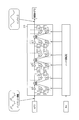
- the block diagram which shows the outline of an engine control system.
- the block diagram which shows the filter process by an IIR filter.
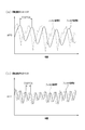
- the time chart which shows the imbalance change waveform and exhaust pulsation noise of a sensor detection signal.
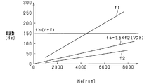
- the figure which shows the frequency characteristic with respect to an engine speed.
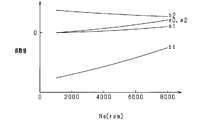
- the figure which shows the correlation of an engine speed and a filter coefficient value.
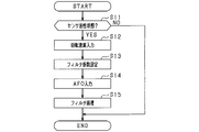
- the flowchart which shows the filter process of 1st Embodiment.
- the time chart which shows the sensor detection voltage AFO before and behind the filter process in when an engine speed is small and large.
- the flowchart which shows the filter process of 2nd Embodiment.
- FIG. 1 is a schematic configuration diagram of an engine control system.
- the engine 10 is an in-line four-cylinder four-cycle gasoline engine.
- the engine 10 is provided with an intake device having an intake manifold 11 and an intake pipe 12 on the upstream side thereof, and an exhaust device having an exhaust manifold 13 and an exhaust pipe 14 on the downstream side thereof.
- An intake passage is formed by the intake device, and an exhaust passage is formed by the exhaust device.
- a throttle valve 15 is provided in the intake pipe 12, and a fuel injection valve 16 is provided in the intake port of the engine 10 for each cylinder.
- An intake pressure sensor 17 for detecting an intake pipe pressure is provided at a collective portion (surge tank) of the intake manifold 11. It should be noted that an in-cylinder injection engine may be employed as the engine 10 instead of the port injection engine.
- an A / F sensor 21 is provided at the assembly portion of the exhaust manifold 13.
- a catalyst 22 such as a three-way catalyst is provided on the downstream side of the A / F sensor 21, that is, on the exhaust pipe 14.
- the A / F sensor 21 has a sensor element made of a solid electrolyte such as zirconia, and generates a sensor detection signal in accordance with the rich component (HC, etc.) and the lean component (O2) of the exhaust, so that the rich region to the lean region
- the air-fuel ratio (A / F) is detected over a wide area. It should be noted that illustration and description of other well-known components such as an intake / exhaust valve and an ignition device in the engine 10 are omitted.
- fuel is injected by the fuel injection valve 16 for each cylinder in a predetermined combustion order (# 1 ⁇ # 3 ⁇ # 4 ⁇ # 2). Inhaled into the combustion chamber. After the air-fuel mixture is combusted in each cylinder, the exhaust gas is sequentially discharged to the exhaust manifold 13 as the exhaust valve (not shown) is opened.
- the ECU 30 is composed mainly of a known microcomputer 31 having a CPU, a ROM, a RAM, and the like, and executes various controls regarding the operation of the engine 10 by executing various control programs stored in the ROM. To do. Specifically, sensor detection signals are sequentially input to the ECU 30 from the above-described intake pressure sensor 17 and A / F sensor 21 and the Ne sensor 23 for detecting the engine rotation speed.
- the microcomputer 31 performs the fuel injection amount control by the fuel injection valve 16, the ignition timing control by the ignition device, and the like based on the intake pressure, the air-fuel ratio, the engine rotation speed, and various parameters representing the respective engine operating states.
- the ECU 30 is provided with a sensor control circuit 32.
- the sensor control circuit 32 includes a current measurement unit and a hard filter unit 34.
- the current measurement unit measures the sensor detection signal of the A / F sensor 21 and amplifies the signal with a predetermined amplification factor.
- the hard filter unit 34 attenuates a signal component having a fixed value or lower than the cutoff frequency fh with respect to the sensor detection signal of the A / F sensor 21.
- a signal after this processing (hereinafter referred to as sensor detection voltage AFO) is output to the microcomputer 31.
- the microcomputer 31 includes an AD conversion unit as an input unit for inputting the sensor detection voltage AFO output from the sensor control circuit 32.
- the sensor detection voltage AFO is AD converted at a predetermined sampling period (2 msec period in the present embodiment).
- the microcomputer 31 includes a soft filter unit 33.
- the soft filter unit 33 includes an IIR filter, and the cutoff frequency fs is determined based on the filter coefficients (a0, a1, a2, b1, b2) of the IIR filter.
- the filter order N of the IIR filter is 3.
- the microcomputer 31 performs air-fuel ratio feedback control so that the actual air-fuel ratio calculated from the output value of the A / F sensor 21 matches the target air-fuel ratio.
- imbalance any one of a plurality of cylinders causes a variation between cylinders (hereinafter referred to as imbalance) in which the fuel injection amount is excessively small or excessive due to a change over time or the like, the exhaust of only that cylinder is on the lean side or Shift to the rich side.
- imbalance change waveform in which the sensor waveform is different only in the corresponding cylinder is generated.
- FIG. 3 shows a case where fuel injection is performed so that the air-fuel ratio of only one cylinder out of four cylinders is rich, and the imbalance changes due to exhaust from the cylinder where the air-fuel ratio was rich.
- a waveform is generated. That is, the A / F sensor 21 detects exhaust for four cylinders of the engine 10 in a predetermined order in time series. If the air-fuel ratio of one cylinder (# 1 in the figure) is rich under the situation where stoichiometric feedback control is being performed, air-fuel ratio fluctuations due to imbalance occur in one cycle at 720 ° CA. It becomes. For this reason, it is desirable to determine the air-fuel ratio imbalance from the detection result of the A / F sensor 21, and to perform the air-fuel ratio feedback control of each cylinder in consideration of the imbalance.
- the exhaust valve is opened in accordance with the combustion of each cylinder and the exhaust is discharged to the exhaust passage, and the exhaust pressure increases every time the exhaust valve in each cylinder is opened. Therefore, when viewed through all the cylinders, as shown in FIG. 3, exhaust pulsation occurs in accordance with the combustion cycle (also the exhaust cycle) of all the cylinders. At this time, the number of molecules per unit volume in the exhaust pipe 14 varies due to exhaust pulsation, and as a result, exhaust pulsation noise is superimposed on the sensor detection voltage AFO. For this reason, there is a possibility that feedback control in consideration of the air-fuel ratio imbalance may not be properly performed.
- the engine rotation speed changes every time, and the exhaust pulsation noise frequency, which is the frequency of the exhaust pulsation noise, and the imbalance frequency, which is the frequency of the imbalance change waveform, change in proportion to the engine rotation speed.
- the cutoff frequency fs is variably set based on the engine speed.
- the filter coefficients (a0, a1, a2, b1, b2) are set so as to take values.
- the filter coefficients (a0, a1, a2, b1, b2) are used as functions of the engine speed, and the filter coefficients are calculated using the relationship shown in FIG.
- the cutoff frequency fs of the IIR filter is uniquely determined between the combustion frequency f1 and the frequency f2 in the entire rotation range of the engine 10, and the exhaust pulsation noise is attenuated in the entire rotation range of the engine 10.
- the filter coefficient of the IIR filter is set so that Thereby, the signal component on the lower frequency side is attenuated as compared with the case where the cutoff frequency fs is closer to the combustion frequency f1.
- the combustion frequency f1 of the engine 10 in the low rotation region and the frequency f2 in the high rotation region have overlapping values.
- the cut-off frequency fh of the hard filter unit 34 is set to a fixed value that attenuates exhaust pulsation noise in the low rotation range, the imbalance change waveform in the high rotation range is smoothed (attenuated). The imbalance change waveform may not be properly detected. Therefore, the cut-off frequency fh of the hard filter unit 34 is a fixed value that is equal to or higher than the frequency f2 in the entire rotation range of the engine 10.
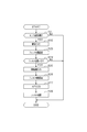
- FIG. 6 is a flowchart showing a signal processing procedure for the sensor detection voltage AFO. This process is repeatedly executed by the microcomputer 31 in the ECU 30 at a predetermined time period (in this embodiment, 2 msec period).
- step S11 the microcomputer 31 determines whether or not the A / F sensor 21 is in the active completion state. If it is not activated, this process is terminated. If the activation is completed, the process proceeds to step S12. In step S12, the microcomputer 31 inputs the engine speed, and then proceeds to step S13.
- step S13 the microcomputer 31 sets the filter coefficient of the IIR filter in the soft filter unit 33 based on the engine speed input in step S12, and after the cutoff frequency fs is determined, the microcomputer 31 proceeds to step S14.
- step S14 the microcomputer 31 inputs the sensor detection voltage AFO and proceeds to step S15.
- step S15 the microcomputer 31 performs filter processing on the sensor detection voltage AFO using an IIR filter, and ends this series of processing.
- FIG. 7A and 7B show waveforms before and after the filter processing of the sensor detection voltage AFO when imbalance occurs.
- FIG. 7A shows a signal waveform at the time of low rotation
- FIG. 7B shows a signal waveform at the time of high rotation.
- the sensor detection voltage AFO greatly fluctuates in a 720 ° CA cycle (four exhaust pulsation noise cycles), and a 180 ° CA cycle (exhaust pulsation).
- the sensor detection voltage AFO fluctuates slightly in one cycle of noise). This is because an air-fuel ratio shift occurs in any one of the four cylinders of the engine 10 and exhaust occurs in the four cylinders of the engine 10. Note that since the air-fuel ratio imbalance has a greater influence on the fluctuation of the sensor detection voltage AFO than the exhaust pulsation, the fluctuation of the sensor detection voltage AFO in the 720 ° CA cycle is larger.
- the combustion cycle of the engine 10 is shorter when the engine speed is high, and therefore the cycle of the exhaust pulsation noise and the imbalance change waveform is shorter.
- the exhaust pulsation noise is properly attenuated and the imbalance change waveform is suppressed from being tempered regardless of the engine speed.
- the exhaust pulsation noise is attenuated in the entire rotation range of the engine 10 by changing the cutoff frequency fs in the soft filter unit 33 based on the engine rotation speed.
- the cutoff frequency fs of the soft filter unit 33 configured by an IIR filter is variably set based on the engine rotation speed. For this reason, the exhaust pulsation noise is appropriately attenuated in the entire rotation range of the engine 10 by the soft filter unit 33, and the imbalance change waveform is prevented from being smoothed. As a result, it is possible to optimize air-fuel ratio detection while ensuring sensor response.
- the cutoff frequency fs is set between the combustion frequency f1 and the frequency f2 obtained by dividing the combustion frequency f1 by the total number of cylinders 4.
- the cutoff frequency fs is set closer to the frequency f2 between the combustion frequency f1 and the frequency f2. According to such a configuration, the attenuation band is wide and the pass band is narrow compared to the case where the cutoff frequency fs is closer to the combustion frequency f1. For this reason, only the imbalance change waveform of the pass band is appropriately extracted. Thereby, determination of imbalance can be implemented appropriately.
- the microcomputer 31 variably sets the filter order N of the soft filter unit 33 based on the engine load. Specifically, when the engine load is high, since the exhaust pressure is large, the exhaust pulsation noise tends to greatly affect the detection accuracy of the imbalance change waveform. For this reason, priority is given to attenuation of exhaust pulsation noise by increasing the filter order N. On the other hand, when the engine load is low, since the exhaust pressure is small, the exhaust pulsation noise hardly affects the detection accuracy of the imbalance change waveform. For this reason, priority is given to reducing the imbalance change waveform by reducing the filter order N. In particular, the difference between the exhaust pulsation frequency and the imbalance frequency is small in the low rotation range. For this reason, by setting the filter order N to be variable, it is possible to prevent the imbalance waveform from being carelessly performed, and to ensure sensor responsiveness.
- the microcomputer 31 variably sets the filter order N based on the intake pressure output from the intake pressure sensor 17 as the engine load. Specifically, the filter order N is reduced when the intake pressure is small. Thereby, it is suppressed that the imbalance change waveform is smoothed according to the engine load.
- FIG. 8 is a flowchart showing a signal processing procedure for the sensor detection voltage AFO. This process is repeatedly executed by the microcomputer 31 in the ECU 30 at a predetermined time period (in this embodiment, 2 msec period).
- step S21 the microcomputer 31 determines whether or not the A / F sensor 21 is in the active completion state. If the microcomputer 31 is inactive, the process is terminated. If the activation is completed, the microcomputer 31 proceeds to step S22.
- step S22 the microcomputer 31 inputs the intake pressure detected by the intake pressure sensor 17. Then, after inputting the intake pressure, in step S23, the microcomputer 31 sets the filter order N based on the intake pressure input in step S22.
- step S24 the microcomputer 31 determines whether or not the filter order N set in step S23 is not zero. If the result in Step S24 is negative, this process is temporarily terminated. If the determination in step S24 is affirmative, the process proceeds to step S25.
- steps S25 to S28 are the same as steps S12 to S15 of FIG. Based on each of these processes, the filter process is performed by the IIR filter in which the filter coefficient is set, and this series of processes ends.
- the filter coefficient is variably set based on the engine rotation speed, and the filter order N is variably set based on the intake pressure. For this reason, the filter processing according to the change in the frequency of the exhaust pulsation noise and the change in the magnitude of the exhaust pulsation is performed, and the imbalance change waveform is suppressed from being smoothed while the exhaust pulsation noise is attenuated. As a result, it is possible to optimize air-fuel ratio detection while ensuring sensor response.
- the filter coefficient of the IIR filter is set so that the cutoff frequency fs becomes a value close to the frequency f2. It is good also as a structure which sets the filter coefficient of an IIR filter so that it may become a value close
- the cutoff frequency fs is increased as the engine speed is increased.
- the filter order N may be reduced as the engine speed increases. As shown in FIG. 4, as the engine speed increases, the difference between the exhaust pulsation noise frequency and the imbalance frequency increases, and the exhaust pulsation noise hardly influences the detection accuracy of the imbalance change waveform in the high rotation range. For this reason, priority is given to reducing the imbalance change waveform by reducing the filter order N.
- the smaller the engine rotation speed the smaller the difference between the exhaust pulsation noise frequency and the imbalance frequency, and the exhaust pulsation noise easily affects the detection accuracy of the imbalance change waveform in the low rotation range.
- the filter order N decreases as the engine load decreases. Even when the engine load is large, the filter order N may be reduced when the engine speed is high. This is because the higher the engine rotation speed, the less influence is exerted on the detection accuracy of the exhaust pulsation frequency. For this reason, when the engine speed is high, the filter order N is reduced to suppress the imbalance change waveform from being smoothed while attenuating the exhaust pulsation noise. As a result, it is possible to optimize air-fuel ratio detection while ensuring sensor response.
- the soft filter unit 33 has an IIR filter, but may have another digital filter such as an FIR filter instead. Even with such a configuration, the filter characteristics can be changed by variably setting the filter coefficient and the filter order N. As a result, the exhaust pulsation noise is appropriately attenuated and the imbalance change waveform is prevented from being smoothed.
- ⁇ Sampling cycle was a predetermined time cycle (2 msec cycle).
- the sampling period may be synchronized with a predetermined crank angle period. According to this configuration, the sampling period changes according to the change in the crank angle period.
- the filter process may be executed intermittently with respect to the sampling period by setting the sampling period to 2 msec and the execution period of the filter process to 10 msec. Thereby, the calculation load of ECU30 with respect to a filter process can be suppressed.
- the A / F sensor 21 is applied to an in-line four-cylinder engine, and the A / F sensor 21 is provided in the collective portion of the exhaust manifold 13.
- the A / F sensor 21 has a common exhaust system, and can be applied to an engine having a plurality of cylinders in which the air-fuel ratio is detected by a common gas sensor.
- an engine having a plurality of banks such as a V-type engine, and an A / F sensor 21 may be provided in each bank.
- This embodiment provides a signal processing device for a gas sensor that is applied to a gas sensor that is provided in an exhaust passage of an engine and detects the concentration of a specific component in the exhaust flowing through the exhaust passage.
- the signal processing device includes filter means for attenuating exhaust pulsation noise included in the detection signal of the gas sensor, and filter characteristic setting means for variably setting the filter characteristic of the filter means based on the engine speed.
- exhaust pulsation noise can be attenuated by using the filter means.
- the detection waveform of the gas concentration is smoothed with the attenuation of the noise, and the sensor responsiveness is lowered.
- the frequency of the exhaust pulsation noise changes depending on the engine rotation speed, there is no inconvenience in a low rotation range, for example.
- inconveniences can occur at high rotational speeds.
- the filter characteristic of the filter means variably based on the engine speed, the exhaust gas pulsation noise is attenuated and the detection of the gas concentration detection waveform is suppressed. As a result, it is possible to optimize gas concentration detection while ensuring sensor response.
Landscapes
- Engineering & Computer Science (AREA)
- Chemical & Material Sciences (AREA)
- Combustion & Propulsion (AREA)
- Mechanical Engineering (AREA)
- General Engineering & Computer Science (AREA)
- Microelectronics & Electronic Packaging (AREA)
- Computer Hardware Design (AREA)
- Analytical Chemistry (AREA)
- Chemical Kinetics & Catalysis (AREA)
- Physics & Mathematics (AREA)
- General Physics & Mathematics (AREA)
- Combined Controls Of Internal Combustion Engines (AREA)
- Electrical Control Of Air Or Fuel Supplied To Internal-Combustion Engine (AREA)
- Exhaust Gas After Treatment (AREA)
Priority Applications (2)
| Application Number | Priority Date | Filing Date | Title |
|---|---|---|---|
| DE112015004355.1T DE112015004355B4 (de) | 2014-09-24 | 2015-09-18 | Signalverarbeitungsvorrichtung für einen Gassensor |
| US15/513,688 US10288526B2 (en) | 2014-09-24 | 2015-09-18 | Signal processing apparatus for gas sensor |
Applications Claiming Priority (2)
| Application Number | Priority Date | Filing Date | Title |
|---|---|---|---|
| JP2014-193796 | 2014-09-24 | ||
| JP2014193796A JP6222027B2 (ja) | 2014-09-24 | 2014-09-24 | ガスセンサの信号処理装置 |
Publications (1)
| Publication Number | Publication Date |
|---|---|
| WO2016047626A1 true WO2016047626A1 (ja) | 2016-03-31 |
Family
ID=55581151
Family Applications (1)
| Application Number | Title | Priority Date | Filing Date |
|---|---|---|---|
| PCT/JP2015/076757 Ceased WO2016047626A1 (ja) | 2014-09-24 | 2015-09-18 | ガスセンサの信号処理装置 |
Country Status (4)
| Country | Link |
|---|---|
| US (1) | US10288526B2 (enExample) |
| JP (1) | JP6222027B2 (enExample) |
| DE (1) | DE112015004355B4 (enExample) |
| WO (1) | WO2016047626A1 (enExample) |
Families Citing this family (2)
| Publication number | Priority date | Publication date | Assignee | Title |
|---|---|---|---|---|
| US11199151B2 (en) * | 2019-06-26 | 2021-12-14 | Cummins Inc. | Vehicle controller with complementary capacitance for analog-to-digital converter (A/D) low pass filter |
| JP2022132769A (ja) * | 2021-03-01 | 2022-09-13 | 村田機械株式会社 | 変位検出装置 |
Citations (3)
| Publication number | Priority date | Publication date | Assignee | Title |
|---|---|---|---|---|
| JP2007332905A (ja) * | 2006-06-16 | 2007-12-27 | Honda Motor Co Ltd | 内燃機関の温度測定装置 |
| JP2010261846A (ja) * | 2009-05-08 | 2010-11-18 | Denso Corp | ガスセンサの信号処理装置 |
| JP2012241554A (ja) * | 2011-05-17 | 2012-12-10 | Mitsubishi Electric Corp | 内燃機関の制御装置 |
Family Cites Families (10)
| Publication number | Priority date | Publication date | Assignee | Title |
|---|---|---|---|---|
| EP1026501B1 (en) | 1999-02-03 | 2010-10-06 | Denso Corporation | Gas concentration measuring apparatus compensating for error component of output signal |
| US6112149A (en) * | 1999-06-28 | 2000-08-29 | Ford Global Technologies, Inc. | Misfire detection system and method using recursive median filtering for high data rate engine control system |
| JP2003269236A (ja) * | 2002-03-18 | 2003-09-25 | Nissan Diesel Motor Co Ltd | エンジンのガス圧検出装置及びパティキュレートフィルタの制御装置 |
| JP4179192B2 (ja) * | 2004-03-08 | 2008-11-12 | 株式会社デンソー | 内燃機関の燃焼状態検出装置 |
| US7292933B2 (en) * | 2004-11-15 | 2007-11-06 | Lotus Engineering, Inc. | Engine misfire detection |
| US7802563B2 (en) | 2008-03-25 | 2010-09-28 | Fors Global Technologies, LLC | Air/fuel imbalance monitor using an oxygen sensor |
| JP4609545B2 (ja) | 2008-08-06 | 2011-01-12 | 株式会社デンソー | ガスセンサの信号処理装置 |
| US7900615B2 (en) | 2008-10-01 | 2011-03-08 | Gm Global Technology Operations, Inc. | Air-fuel imbalance detection based on zero-phase filtering |
| JP2010203413A (ja) | 2009-03-05 | 2010-09-16 | Denso Corp | 内燃機関の気筒別空燃比制御装置 |
| JP5138712B2 (ja) | 2010-01-19 | 2013-02-06 | 日立オートモティブシステムズ株式会社 | 過給機付きエンジンの制御装置 |
-
2014
- 2014-09-24 JP JP2014193796A patent/JP6222027B2/ja active Active
-
2015
- 2015-09-18 DE DE112015004355.1T patent/DE112015004355B4/de not_active Expired - Fee Related
- 2015-09-18 WO PCT/JP2015/076757 patent/WO2016047626A1/ja not_active Ceased
- 2015-09-18 US US15/513,688 patent/US10288526B2/en not_active Expired - Fee Related
Patent Citations (3)
| Publication number | Priority date | Publication date | Assignee | Title |
|---|---|---|---|---|
| JP2007332905A (ja) * | 2006-06-16 | 2007-12-27 | Honda Motor Co Ltd | 内燃機関の温度測定装置 |
| JP2010261846A (ja) * | 2009-05-08 | 2010-11-18 | Denso Corp | ガスセンサの信号処理装置 |
| JP2012241554A (ja) * | 2011-05-17 | 2012-12-10 | Mitsubishi Electric Corp | 内燃機関の制御装置 |
Also Published As
| Publication number | Publication date |
|---|---|
| JP2016065473A (ja) | 2016-04-28 |
| US20170307477A1 (en) | 2017-10-26 |
| JP6222027B2 (ja) | 2017-11-01 |
| DE112015004355B4 (de) | 2022-04-21 |
| US10288526B2 (en) | 2019-05-14 |
| DE112015004355T5 (de) | 2017-06-14 |
Similar Documents
| Publication | Publication Date | Title |
|---|---|---|
| JP4130800B2 (ja) | エンジンの制御装置 | |
| JP6362713B2 (ja) | ノック検出装置 | |
| JP2011027059A (ja) | エンジンの制御装置 | |
| JP2009270543A (ja) | 気筒間の空燃比の不均衡を判断するための装置 | |
| JP6136341B2 (ja) | 内燃機関の異常燃焼検出装置 | |
| US9587575B2 (en) | Cylinder-to-cylinder variation abnormality detecting device | |
| JP6006228B2 (ja) | 筒内圧センサの異常診断装置及びこれを備えた筒内圧センサの感度補正装置 | |
| JP6222027B2 (ja) | ガスセンサの信号処理装置 | |
| JP5152097B2 (ja) | ガスセンサの信号処理装置 | |
| JP2019128308A (ja) | 空気流量測定装置 | |
| JP2008180225A (ja) | エンジンの制御装置 | |
| JP2013083186A (ja) | 空燃比インバランス気筒決定装置 | |
| JP5212194B2 (ja) | 内燃機関の制御装置 | |
| JP2009209865A (ja) | ノック検出系異常診断置 | |
| JP6608794B2 (ja) | 内燃機関の制御装置 | |
| US5067466A (en) | System for measuring air flow rate for internal combustion engines | |
| JP2012117463A (ja) | 気筒間空燃比ばらつき異常検出装置 | |
| JP4361917B2 (ja) | エンジンの制御装置 | |
| JP5260770B2 (ja) | エンジンの制御装置 | |
| JP6407828B2 (ja) | 内燃機関の制御装置 | |
| JP2005240618A (ja) | エンジンの制御装置 | |
| JP5472270B2 (ja) | 車両の制御装置 | |
| JP5537510B2 (ja) | 内燃機関の気筒判定装置 | |
| JP5342618B2 (ja) | 内燃機関の空燃比制御装置 | |
| JP2014013017A (ja) | 空燃比センサ感受性評価装置および気筒間空燃比ばらつき異常検出装置 |
Legal Events
| Date | Code | Title | Description |
|---|---|---|---|
| 121 | Ep: the epo has been informed by wipo that ep was designated in this application |
Ref document number: 15844655 Country of ref document: EP Kind code of ref document: A1 |
|
| WWE | Wipo information: entry into national phase |
Ref document number: 15513688 Country of ref document: US |
|
| WWE | Wipo information: entry into national phase |
Ref document number: 112015004355 Country of ref document: DE |
|
| 122 | Ep: pct application non-entry in european phase |
Ref document number: 15844655 Country of ref document: EP Kind code of ref document: A1 |