WO2016047626A1 - Signal processing device of gas sensor - Google Patents
Signal processing device of gas sensor Download PDFInfo
- Publication number
- WO2016047626A1 WO2016047626A1 PCT/JP2015/076757 JP2015076757W WO2016047626A1 WO 2016047626 A1 WO2016047626 A1 WO 2016047626A1 JP 2015076757 W JP2015076757 W JP 2015076757W WO 2016047626 A1 WO2016047626 A1 WO 2016047626A1
- Authority
- WO
- WIPO (PCT)
- Prior art keywords
- filter
- engine
- gas sensor
- frequency
- exhaust
- Prior art date
Links
Images


Classifications
-
- G—PHYSICS
- G01—MEASURING; TESTING
- G01M—TESTING STATIC OR DYNAMIC BALANCE OF MACHINES OR STRUCTURES; TESTING OF STRUCTURES OR APPARATUS, NOT OTHERWISE PROVIDED FOR
- G01M15/00—Testing of engines
- G01M15/04—Testing internal-combustion engines
- G01M15/10—Testing internal-combustion engines by monitoring exhaust gases or combustion flame
- G01M15/102—Testing internal-combustion engines by monitoring exhaust gases or combustion flame by monitoring exhaust gases
-
- F—MECHANICAL ENGINEERING; LIGHTING; HEATING; WEAPONS; BLASTING
- F02—COMBUSTION ENGINES; HOT-GAS OR COMBUSTION-PRODUCT ENGINE PLANTS
- F02D—CONTROLLING COMBUSTION ENGINES
- F02D41/00—Electrical control of supply of combustible mixture or its constituents
- F02D41/02—Circuit arrangements for generating control signals
- F02D41/14—Introducing closed-loop corrections
- F02D41/1438—Introducing closed-loop corrections using means for determining characteristics of the combustion gases; Sensors therefor
- F02D41/1444—Introducing closed-loop corrections using means for determining characteristics of the combustion gases; Sensors therefor characterised by the characteristics of the combustion gases
- F02D41/1454—Introducing closed-loop corrections using means for determining characteristics of the combustion gases; Sensors therefor characterised by the characteristics of the combustion gases the characteristics being an oxygen content or concentration or the air-fuel ratio
-
- F—MECHANICAL ENGINEERING; LIGHTING; HEATING; WEAPONS; BLASTING
- F01—MACHINES OR ENGINES IN GENERAL; ENGINE PLANTS IN GENERAL; STEAM ENGINES
- F01N—GAS-FLOW SILENCERS OR EXHAUST APPARATUS FOR MACHINES OR ENGINES IN GENERAL; GAS-FLOW SILENCERS OR EXHAUST APPARATUS FOR INTERNAL COMBUSTION ENGINES
- F01N11/00—Monitoring or diagnostic devices for exhaust-gas treatment apparatus, e.g. for catalytic activity
-
- F—MECHANICAL ENGINEERING; LIGHTING; HEATING; WEAPONS; BLASTING
- F01—MACHINES OR ENGINES IN GENERAL; ENGINE PLANTS IN GENERAL; STEAM ENGINES
- F01N—GAS-FLOW SILENCERS OR EXHAUST APPARATUS FOR MACHINES OR ENGINES IN GENERAL; GAS-FLOW SILENCERS OR EXHAUST APPARATUS FOR INTERNAL COMBUSTION ENGINES
- F01N13/00—Exhaust or silencing apparatus characterised by constructional features ; Exhaust or silencing apparatus, or parts thereof, having pertinent characteristics not provided for in, or of interest apart from, groups F01N1/00 - F01N5/00, F01N9/00, F01N11/00
- F01N13/008—Mounting or arrangement of exhaust sensors in or on exhaust apparatus
-
- F—MECHANICAL ENGINEERING; LIGHTING; HEATING; WEAPONS; BLASTING
- F02—COMBUSTION ENGINES; HOT-GAS OR COMBUSTION-PRODUCT ENGINE PLANTS
- F02D—CONTROLLING COMBUSTION ENGINES
- F02D41/00—Electrical control of supply of combustible mixture or its constituents
- F02D41/02—Circuit arrangements for generating control signals
- F02D41/14—Introducing closed-loop corrections
- F02D41/1438—Introducing closed-loop corrections using means for determining characteristics of the combustion gases; Sensors therefor
- F02D41/1486—Introducing closed-loop corrections using means for determining characteristics of the combustion gases; Sensors therefor with correction for particular operating conditions
-
- F—MECHANICAL ENGINEERING; LIGHTING; HEATING; WEAPONS; BLASTING
- F02—COMBUSTION ENGINES; HOT-GAS OR COMBUSTION-PRODUCT ENGINE PLANTS
- F02D—CONTROLLING COMBUSTION ENGINES
- F02D41/00—Electrical control of supply of combustible mixture or its constituents
- F02D41/24—Electrical control of supply of combustible mixture or its constituents characterised by the use of digital means
- F02D41/26—Electrical control of supply of combustible mixture or its constituents characterised by the use of digital means using computer, e.g. microprocessor
- F02D41/28—Interface circuits
-
- F—MECHANICAL ENGINEERING; LIGHTING; HEATING; WEAPONS; BLASTING
- F02—COMBUSTION ENGINES; HOT-GAS OR COMBUSTION-PRODUCT ENGINE PLANTS
- F02D—CONTROLLING COMBUSTION ENGINES
- F02D41/00—Electrical control of supply of combustible mixture or its constituents
- F02D41/02—Circuit arrangements for generating control signals
- F02D41/14—Introducing closed-loop corrections
- F02D41/1401—Introducing closed-loop corrections characterised by the control or regulation method
- F02D2041/1413—Controller structures or design
- F02D2041/1432—Controller structures or design the system including a filter, e.g. a low pass or high pass filter
-
- F—MECHANICAL ENGINEERING; LIGHTING; HEATING; WEAPONS; BLASTING
- F02—COMBUSTION ENGINES; HOT-GAS OR COMBUSTION-PRODUCT ENGINE PLANTS
- F02D—CONTROLLING COMBUSTION ENGINES
- F02D41/00—Electrical control of supply of combustible mixture or its constituents
- F02D41/24—Electrical control of supply of combustible mixture or its constituents characterised by the use of digital means
- F02D41/26—Electrical control of supply of combustible mixture or its constituents characterised by the use of digital means using computer, e.g. microprocessor
- F02D41/28—Interface circuits
- F02D2041/281—Interface circuits between sensors and control unit
-
- F—MECHANICAL ENGINEERING; LIGHTING; HEATING; WEAPONS; BLASTING
- F02—COMBUSTION ENGINES; HOT-GAS OR COMBUSTION-PRODUCT ENGINE PLANTS
- F02D—CONTROLLING COMBUSTION ENGINES
- F02D41/00—Electrical control of supply of combustible mixture or its constituents
- F02D41/24—Electrical control of supply of combustible mixture or its constituents characterised by the use of digital means
- F02D41/26—Electrical control of supply of combustible mixture or its constituents characterised by the use of digital means using computer, e.g. microprocessor
- F02D41/28—Interface circuits
- F02D2041/286—Interface circuits comprising means for signal processing
-
- F—MECHANICAL ENGINEERING; LIGHTING; HEATING; WEAPONS; BLASTING
- F02—COMBUSTION ENGINES; HOT-GAS OR COMBUSTION-PRODUCT ENGINE PLANTS
- F02D—CONTROLLING COMBUSTION ENGINES
- F02D2200/00—Input parameters for engine control
- F02D2200/02—Input parameters for engine control the parameters being related to the engine
- F02D2200/10—Parameters related to the engine output, e.g. engine torque or engine speed
- F02D2200/101—Engine speed
-
- F—MECHANICAL ENGINEERING; LIGHTING; HEATING; WEAPONS; BLASTING
- F02—COMBUSTION ENGINES; HOT-GAS OR COMBUSTION-PRODUCT ENGINE PLANTS
- F02D—CONTROLLING COMBUSTION ENGINES
- F02D41/00—Electrical control of supply of combustible mixture or its constituents
- F02D41/02—Circuit arrangements for generating control signals
- F02D41/14—Introducing closed-loop corrections
- F02D41/1438—Introducing closed-loop corrections using means for determining characteristics of the combustion gases; Sensors therefor
- F02D41/1493—Details
- F02D41/1495—Detection of abnormalities in the air/fuel ratio feedback system
Definitions
- the present invention relates to a signal processing device for a gas sensor applied to a gas sensor for detecting the concentration of a specific component in engine exhaust.
- This type of gas sensor has been put to practical use as an A / F sensor provided in an exhaust passage of an engine, for example, and feedback control is performed so that the actual air-fuel ratio detected by the A / F sensor matches the target air-fuel ratio.
- the detection accuracy of the air-fuel ratio is lowered.
- a technique has been put to practical use in which a low-pass filter circuit is provided in the control circuit unit for inputting the detection signal of the A / F sensor and noise is removed by the low-pass filter circuit.
- Patent Document 1 focuses on the fact that when exhaust pulsation occurs during supercharging by the supercharger, the exhaust pulsation rides on the sensor detection signal as noise.
- Patent Document 1 discloses a technique in which, in a supercharged state, the detection signal of the gas sensor is filtered by a filter unit, and the filter mode is corrected based on the intake pipe pressure.
- One embodiment provides a signal processing device for a gas sensor that suppresses unintentionally distorting a detection waveform of a gas concentration in a sensor detection signal, and thus can appropriately detect the gas concentration.
- the gas sensor signal processing device of one embodiment is applied to a gas sensor that is provided in an exhaust passage of an engine and detects the concentration of a specific component in exhaust flowing in the exhaust passage.
- the signal processing device includes filter means for attenuating exhaust pulsation noise included in the detection signal of the gas sensor, and filter characteristic setting means for variably setting the filter characteristic of the filter means based on the engine speed.
- the block diagram which shows the outline of an engine control system.
- the block diagram which shows the filter process by an IIR filter.
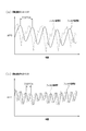
- the time chart which shows the imbalance change waveform and exhaust pulsation noise of a sensor detection signal.
- the figure which shows the frequency characteristic with respect to an engine speed.
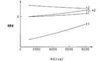
- the figure which shows the correlation of an engine speed and a filter coefficient value.
- the flowchart which shows the filter process of 1st Embodiment.
- the time chart which shows the sensor detection voltage AFO before and behind the filter process in when an engine speed is small and large.
- the flowchart which shows the filter process of 2nd Embodiment.
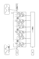
- FIG. 1 is a schematic configuration diagram of an engine control system.
- the engine 10 is an in-line four-cylinder four-cycle gasoline engine.
- the engine 10 is provided with an intake device having an intake manifold 11 and an intake pipe 12 on the upstream side thereof, and an exhaust device having an exhaust manifold 13 and an exhaust pipe 14 on the downstream side thereof.
- An intake passage is formed by the intake device, and an exhaust passage is formed by the exhaust device.
- a throttle valve 15 is provided in the intake pipe 12, and a fuel injection valve 16 is provided in the intake port of the engine 10 for each cylinder.
- An intake pressure sensor 17 for detecting an intake pipe pressure is provided at a collective portion (surge tank) of the intake manifold 11. It should be noted that an in-cylinder injection engine may be employed as the engine 10 instead of the port injection engine.
- an A / F sensor 21 is provided at the assembly portion of the exhaust manifold 13.
- a catalyst 22 such as a three-way catalyst is provided on the downstream side of the A / F sensor 21, that is, on the exhaust pipe 14.
- the A / F sensor 21 has a sensor element made of a solid electrolyte such as zirconia, and generates a sensor detection signal in accordance with the rich component (HC, etc.) and the lean component (O2) of the exhaust, so that the rich region to the lean region
- the air-fuel ratio (A / F) is detected over a wide area. It should be noted that illustration and description of other well-known components such as an intake / exhaust valve and an ignition device in the engine 10 are omitted.
- fuel is injected by the fuel injection valve 16 for each cylinder in a predetermined combustion order (# 1 ⁇ # 3 ⁇ # 4 ⁇ # 2). Inhaled into the combustion chamber. After the air-fuel mixture is combusted in each cylinder, the exhaust gas is sequentially discharged to the exhaust manifold 13 as the exhaust valve (not shown) is opened.
- the ECU 30 is composed mainly of a known microcomputer 31 having a CPU, a ROM, a RAM, and the like, and executes various controls regarding the operation of the engine 10 by executing various control programs stored in the ROM. To do. Specifically, sensor detection signals are sequentially input to the ECU 30 from the above-described intake pressure sensor 17 and A / F sensor 21 and the Ne sensor 23 for detecting the engine rotation speed.
- the microcomputer 31 performs the fuel injection amount control by the fuel injection valve 16, the ignition timing control by the ignition device, and the like based on the intake pressure, the air-fuel ratio, the engine rotation speed, and various parameters representing the respective engine operating states.
- the ECU 30 is provided with a sensor control circuit 32.
- the sensor control circuit 32 includes a current measurement unit and a hard filter unit 34.
- the current measurement unit measures the sensor detection signal of the A / F sensor 21 and amplifies the signal with a predetermined amplification factor.
- the hard filter unit 34 attenuates a signal component having a fixed value or lower than the cutoff frequency fh with respect to the sensor detection signal of the A / F sensor 21.
- a signal after this processing (hereinafter referred to as sensor detection voltage AFO) is output to the microcomputer 31.
- the microcomputer 31 includes an AD conversion unit as an input unit for inputting the sensor detection voltage AFO output from the sensor control circuit 32.
- the sensor detection voltage AFO is AD converted at a predetermined sampling period (2 msec period in the present embodiment).
- the microcomputer 31 includes a soft filter unit 33.
- the soft filter unit 33 includes an IIR filter, and the cutoff frequency fs is determined based on the filter coefficients (a0, a1, a2, b1, b2) of the IIR filter.
- the filter order N of the IIR filter is 3.
- the microcomputer 31 performs air-fuel ratio feedback control so that the actual air-fuel ratio calculated from the output value of the A / F sensor 21 matches the target air-fuel ratio.
- imbalance any one of a plurality of cylinders causes a variation between cylinders (hereinafter referred to as imbalance) in which the fuel injection amount is excessively small or excessive due to a change over time or the like, the exhaust of only that cylinder is on the lean side or Shift to the rich side.
- imbalance change waveform in which the sensor waveform is different only in the corresponding cylinder is generated.
- FIG. 3 shows a case where fuel injection is performed so that the air-fuel ratio of only one cylinder out of four cylinders is rich, and the imbalance changes due to exhaust from the cylinder where the air-fuel ratio was rich.
- a waveform is generated. That is, the A / F sensor 21 detects exhaust for four cylinders of the engine 10 in a predetermined order in time series. If the air-fuel ratio of one cylinder (# 1 in the figure) is rich under the situation where stoichiometric feedback control is being performed, air-fuel ratio fluctuations due to imbalance occur in one cycle at 720 ° CA. It becomes. For this reason, it is desirable to determine the air-fuel ratio imbalance from the detection result of the A / F sensor 21, and to perform the air-fuel ratio feedback control of each cylinder in consideration of the imbalance.
- the exhaust valve is opened in accordance with the combustion of each cylinder and the exhaust is discharged to the exhaust passage, and the exhaust pressure increases every time the exhaust valve in each cylinder is opened. Therefore, when viewed through all the cylinders, as shown in FIG. 3, exhaust pulsation occurs in accordance with the combustion cycle (also the exhaust cycle) of all the cylinders. At this time, the number of molecules per unit volume in the exhaust pipe 14 varies due to exhaust pulsation, and as a result, exhaust pulsation noise is superimposed on the sensor detection voltage AFO. For this reason, there is a possibility that feedback control in consideration of the air-fuel ratio imbalance may not be properly performed.
- the engine rotation speed changes every time, and the exhaust pulsation noise frequency, which is the frequency of the exhaust pulsation noise, and the imbalance frequency, which is the frequency of the imbalance change waveform, change in proportion to the engine rotation speed.
- the cutoff frequency fs is variably set based on the engine speed.
- the filter coefficients (a0, a1, a2, b1, b2) are set so as to take values.
- the filter coefficients (a0, a1, a2, b1, b2) are used as functions of the engine speed, and the filter coefficients are calculated using the relationship shown in FIG.
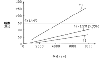
- the cutoff frequency fs of the IIR filter is uniquely determined between the combustion frequency f1 and the frequency f2 in the entire rotation range of the engine 10, and the exhaust pulsation noise is attenuated in the entire rotation range of the engine 10.
- the filter coefficient of the IIR filter is set so that Thereby, the signal component on the lower frequency side is attenuated as compared with the case where the cutoff frequency fs is closer to the combustion frequency f1.
- the combustion frequency f1 of the engine 10 in the low rotation region and the frequency f2 in the high rotation region have overlapping values.
- the cut-off frequency fh of the hard filter unit 34 is set to a fixed value that attenuates exhaust pulsation noise in the low rotation range, the imbalance change waveform in the high rotation range is smoothed (attenuated). The imbalance change waveform may not be properly detected. Therefore, the cut-off frequency fh of the hard filter unit 34 is a fixed value that is equal to or higher than the frequency f2 in the entire rotation range of the engine 10.
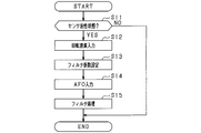
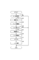
- FIG. 6 is a flowchart showing a signal processing procedure for the sensor detection voltage AFO. This process is repeatedly executed by the microcomputer 31 in the ECU 30 at a predetermined time period (in this embodiment, 2 msec period).
- step S11 the microcomputer 31 determines whether or not the A / F sensor 21 is in the active completion state. If it is not activated, this process is terminated. If the activation is completed, the process proceeds to step S12. In step S12, the microcomputer 31 inputs the engine speed, and then proceeds to step S13.
- step S13 the microcomputer 31 sets the filter coefficient of the IIR filter in the soft filter unit 33 based on the engine speed input in step S12, and after the cutoff frequency fs is determined, the microcomputer 31 proceeds to step S14.
- step S14 the microcomputer 31 inputs the sensor detection voltage AFO and proceeds to step S15.
- step S15 the microcomputer 31 performs filter processing on the sensor detection voltage AFO using an IIR filter, and ends this series of processing.
- FIG. 7A and 7B show waveforms before and after the filter processing of the sensor detection voltage AFO when imbalance occurs.
- FIG. 7A shows a signal waveform at the time of low rotation
- FIG. 7B shows a signal waveform at the time of high rotation.
- the sensor detection voltage AFO greatly fluctuates in a 720 ° CA cycle (four exhaust pulsation noise cycles), and a 180 ° CA cycle (exhaust pulsation).
- the sensor detection voltage AFO fluctuates slightly in one cycle of noise). This is because an air-fuel ratio shift occurs in any one of the four cylinders of the engine 10 and exhaust occurs in the four cylinders of the engine 10. Note that since the air-fuel ratio imbalance has a greater influence on the fluctuation of the sensor detection voltage AFO than the exhaust pulsation, the fluctuation of the sensor detection voltage AFO in the 720 ° CA cycle is larger.
- the combustion cycle of the engine 10 is shorter when the engine speed is high, and therefore the cycle of the exhaust pulsation noise and the imbalance change waveform is shorter.
- the exhaust pulsation noise is properly attenuated and the imbalance change waveform is suppressed from being tempered regardless of the engine speed.
- the exhaust pulsation noise is attenuated in the entire rotation range of the engine 10 by changing the cutoff frequency fs in the soft filter unit 33 based on the engine rotation speed.
- the cutoff frequency fs of the soft filter unit 33 configured by an IIR filter is variably set based on the engine rotation speed. For this reason, the exhaust pulsation noise is appropriately attenuated in the entire rotation range of the engine 10 by the soft filter unit 33, and the imbalance change waveform is prevented from being smoothed. As a result, it is possible to optimize air-fuel ratio detection while ensuring sensor response.
- the cutoff frequency fs is set between the combustion frequency f1 and the frequency f2 obtained by dividing the combustion frequency f1 by the total number of cylinders 4.
- the cutoff frequency fs is set closer to the frequency f2 between the combustion frequency f1 and the frequency f2. According to such a configuration, the attenuation band is wide and the pass band is narrow compared to the case where the cutoff frequency fs is closer to the combustion frequency f1. For this reason, only the imbalance change waveform of the pass band is appropriately extracted. Thereby, determination of imbalance can be implemented appropriately.
- the microcomputer 31 variably sets the filter order N of the soft filter unit 33 based on the engine load. Specifically, when the engine load is high, since the exhaust pressure is large, the exhaust pulsation noise tends to greatly affect the detection accuracy of the imbalance change waveform. For this reason, priority is given to attenuation of exhaust pulsation noise by increasing the filter order N. On the other hand, when the engine load is low, since the exhaust pressure is small, the exhaust pulsation noise hardly affects the detection accuracy of the imbalance change waveform. For this reason, priority is given to reducing the imbalance change waveform by reducing the filter order N. In particular, the difference between the exhaust pulsation frequency and the imbalance frequency is small in the low rotation range. For this reason, by setting the filter order N to be variable, it is possible to prevent the imbalance waveform from being carelessly performed, and to ensure sensor responsiveness.
- the microcomputer 31 variably sets the filter order N based on the intake pressure output from the intake pressure sensor 17 as the engine load. Specifically, the filter order N is reduced when the intake pressure is small. Thereby, it is suppressed that the imbalance change waveform is smoothed according to the engine load.
- FIG. 8 is a flowchart showing a signal processing procedure for the sensor detection voltage AFO. This process is repeatedly executed by the microcomputer 31 in the ECU 30 at a predetermined time period (in this embodiment, 2 msec period).
- step S21 the microcomputer 31 determines whether or not the A / F sensor 21 is in the active completion state. If the microcomputer 31 is inactive, the process is terminated. If the activation is completed, the microcomputer 31 proceeds to step S22.
- step S22 the microcomputer 31 inputs the intake pressure detected by the intake pressure sensor 17. Then, after inputting the intake pressure, in step S23, the microcomputer 31 sets the filter order N based on the intake pressure input in step S22.
- step S24 the microcomputer 31 determines whether or not the filter order N set in step S23 is not zero. If the result in Step S24 is negative, this process is temporarily terminated. If the determination in step S24 is affirmative, the process proceeds to step S25.
- steps S25 to S28 are the same as steps S12 to S15 of FIG. Based on each of these processes, the filter process is performed by the IIR filter in which the filter coefficient is set, and this series of processes ends.
- the filter coefficient is variably set based on the engine rotation speed, and the filter order N is variably set based on the intake pressure. For this reason, the filter processing according to the change in the frequency of the exhaust pulsation noise and the change in the magnitude of the exhaust pulsation is performed, and the imbalance change waveform is suppressed from being smoothed while the exhaust pulsation noise is attenuated. As a result, it is possible to optimize air-fuel ratio detection while ensuring sensor response.
- the filter coefficient of the IIR filter is set so that the cutoff frequency fs becomes a value close to the frequency f2. It is good also as a structure which sets the filter coefficient of an IIR filter so that it may become a value close
- the cutoff frequency fs is increased as the engine speed is increased.
- the filter order N may be reduced as the engine speed increases. As shown in FIG. 4, as the engine speed increases, the difference between the exhaust pulsation noise frequency and the imbalance frequency increases, and the exhaust pulsation noise hardly influences the detection accuracy of the imbalance change waveform in the high rotation range. For this reason, priority is given to reducing the imbalance change waveform by reducing the filter order N.
- the smaller the engine rotation speed the smaller the difference between the exhaust pulsation noise frequency and the imbalance frequency, and the exhaust pulsation noise easily affects the detection accuracy of the imbalance change waveform in the low rotation range.
- the filter order N decreases as the engine load decreases. Even when the engine load is large, the filter order N may be reduced when the engine speed is high. This is because the higher the engine rotation speed, the less influence is exerted on the detection accuracy of the exhaust pulsation frequency. For this reason, when the engine speed is high, the filter order N is reduced to suppress the imbalance change waveform from being smoothed while attenuating the exhaust pulsation noise. As a result, it is possible to optimize air-fuel ratio detection while ensuring sensor response.
- the soft filter unit 33 has an IIR filter, but may have another digital filter such as an FIR filter instead. Even with such a configuration, the filter characteristics can be changed by variably setting the filter coefficient and the filter order N. As a result, the exhaust pulsation noise is appropriately attenuated and the imbalance change waveform is prevented from being smoothed.
- ⁇ Sampling cycle was a predetermined time cycle (2 msec cycle).
- the sampling period may be synchronized with a predetermined crank angle period. According to this configuration, the sampling period changes according to the change in the crank angle period.
- the filter process may be executed intermittently with respect to the sampling period by setting the sampling period to 2 msec and the execution period of the filter process to 10 msec. Thereby, the calculation load of ECU30 with respect to a filter process can be suppressed.
- the A / F sensor 21 is applied to an in-line four-cylinder engine, and the A / F sensor 21 is provided in the collective portion of the exhaust manifold 13.
- the A / F sensor 21 has a common exhaust system, and can be applied to an engine having a plurality of cylinders in which the air-fuel ratio is detected by a common gas sensor.
- an engine having a plurality of banks such as a V-type engine, and an A / F sensor 21 may be provided in each bank.
- This embodiment provides a signal processing device for a gas sensor that is applied to a gas sensor that is provided in an exhaust passage of an engine and detects the concentration of a specific component in the exhaust flowing through the exhaust passage.
- the signal processing device includes filter means for attenuating exhaust pulsation noise included in the detection signal of the gas sensor, and filter characteristic setting means for variably setting the filter characteristic of the filter means based on the engine speed.
- exhaust pulsation noise can be attenuated by using the filter means.
- the detection waveform of the gas concentration is smoothed with the attenuation of the noise, and the sensor responsiveness is lowered.
- the frequency of the exhaust pulsation noise changes depending on the engine rotation speed, there is no inconvenience in a low rotation range, for example.
- inconveniences can occur at high rotational speeds.
- the filter characteristic of the filter means variably based on the engine speed, the exhaust gas pulsation noise is attenuated and the detection of the gas concentration detection waveform is suppressed. As a result, it is possible to optimize gas concentration detection while ensuring sensor response.
Landscapes
- Engineering & Computer Science (AREA)
- Chemical & Material Sciences (AREA)
- Combustion & Propulsion (AREA)
- Mechanical Engineering (AREA)
- General Engineering & Computer Science (AREA)
- Microelectronics & Electronic Packaging (AREA)
- Computer Hardware Design (AREA)
- Analytical Chemistry (AREA)
- Chemical Kinetics & Catalysis (AREA)
- Physics & Mathematics (AREA)
- General Physics & Mathematics (AREA)
- Combined Controls Of Internal Combustion Engines (AREA)
- Electrical Control Of Air Or Fuel Supplied To Internal-Combustion Engine (AREA)
Abstract
A signal processing device of a gas sensor is applied to a gas sensor which is provided to an engine exhaust passage and which detects the concentration of specific components in exhaust gas flowing through the exhaust passage. This signal processing device is provided with a filter means for reducing exhaust pulse noise included within the detection signal of the gas sensor, and a filter characteristic setting means for variably setting the filter characteristics of the filter means on the basis of the engine speed.
Description
本発明は、エンジンの排気中における特定成分の濃度を検出するガスセンサに適用されるガスセンサの信号処理装置に関する。
The present invention relates to a signal processing device for a gas sensor applied to a gas sensor for detecting the concentration of a specific component in engine exhaust.
この種のガスセンサは、例えばエンジンの排気通路に設けられるA/Fセンサとして実用化されており、A/Fセンサにより検出された実空燃比を目標空燃比に一致させるべくフィードバック制御が実施される。ここで、エンジンの運転時においてはそのエンジン運転に起因して生じるノイズがA/Fセンサの検出信号に重畳し、結果として空燃比の検出精度の低下が生じることが懸念される。そこで、A/Fセンサの検出信号を入力する制御回路部にローパスフィルタ回路を設け、そのローパスフィルタ回路によりノイズ除去を行うようにした技術が実用化されている。
This type of gas sensor has been put to practical use as an A / F sensor provided in an exhaust passage of an engine, for example, and feedback control is performed so that the actual air-fuel ratio detected by the A / F sensor matches the target air-fuel ratio. . Here, when the engine is operating, there is a concern that noise caused by the engine operation is superimposed on the detection signal of the A / F sensor, and as a result, the detection accuracy of the air-fuel ratio is lowered. In view of this, a technique has been put to practical use in which a low-pass filter circuit is provided in the control circuit unit for inputting the detection signal of the A / F sensor and noise is removed by the low-pass filter circuit.
また、例えば特許文献1には、過給機による過給時に排気脈動が生じると、その排気脈動がセンサ検出信号にノイズとして乗ることに着目している。特許文献1には、過給状態である場合に、ガスセンサの検出信号をフィルタ手段によりフィルタ処理するとともに、吸気管内圧力に基づいてフィルタ態様を補正するようにした技術が開示されている。
For example, Patent Document 1 focuses on the fact that when exhaust pulsation occurs during supercharging by the supercharger, the exhaust pulsation rides on the sensor detection signal as noise. Patent Document 1 discloses a technique in which, in a supercharged state, the detection signal of the gas sensor is filtered by a filter unit, and the filter mode is corrected based on the intake pipe pressure.
しかしながら、ガスセンサの検出信号に対してフィルタ処理を実施する場合、ノイズの除去に加えて、本来の検出対象であるガス濃度の検出波形までもがなまされてしまう(減衰される)ことが懸念される。例えば、上記特許文献1に記載のものでは、センサ検出信号に重畳する排気脈動ノイズを除去する際において、ガス濃度の検出波形がなまされてしまい、結果としてガス濃度の検出精度が低下することが懸念される。この点、改善の余地があると考えられる。
However, when filter processing is performed on the detection signal of the gas sensor, in addition to removing noise, there is a concern that the detection waveform of the gas concentration that is the original detection target is also distorted (attenuated). Is done. For example, in the thing of the said patent document 1, when removing the exhaust pulsation noise superimposed on a sensor detection signal, the detection waveform of gas concentration will be smoothed, and, as a result, the detection accuracy of gas concentration falls. Is concerned. There is room for improvement in this regard.
一実施形態は、センサ検出信号におけるガス濃度の検出波形が意図せずなまされることを抑制し、ひいてはガス濃度の検出を適正に実施することができるガスセンサの信号処理装置を提供する。
One embodiment provides a signal processing device for a gas sensor that suppresses unintentionally distorting a detection waveform of a gas concentration in a sensor detection signal, and thus can appropriately detect the gas concentration.
一実施形態のガスセンサの信号処理装置は、エンジンの排気通路に設けられ該排気通路内を流れる排気中の特定成分の濃度を検出するガスセンサに適用される。この信号処理装置は、前記ガスセンサの検出信号に含まれる排気脈動ノイズを減衰するフィルタ手段と、エンジン回転速度に基づいて前記フィルタ手段のフィルタ特性を可変に設定するフィルタ特性設定手段と、を備える。
The gas sensor signal processing device of one embodiment is applied to a gas sensor that is provided in an exhaust passage of an engine and detects the concentration of a specific component in exhaust flowing in the exhaust passage. The signal processing device includes filter means for attenuating exhaust pulsation noise included in the detection signal of the gas sensor, and filter characteristic setting means for variably setting the filter characteristic of the filter means based on the engine speed.
(第1実施形態)
以下、本発明を具体化した一実施形態を図面に基づいて説明する。本実施形態は、車両に搭載される多気筒火花点火式のガソリンエンジンを制御対象とするエンジン制御システムに具体化しており、電子制御ユニット(ECU)により同エンジンの運転状態を制御する。図1は、エンジン制御システムの概略構成図である。 (First embodiment)
DESCRIPTION OF EXEMPLARY EMBODIMENTS Hereinafter, an embodiment of the invention will be described with reference to the drawings. The present embodiment is embodied in an engine control system that controls a multi-cylinder spark ignition gasoline engine mounted on a vehicle, and an electronic control unit (ECU) controls the operating state of the engine. FIG. 1 is a schematic configuration diagram of an engine control system.
図1において、エンジン10は直列4気筒4サイクルガソリンエンジンである。エンジン10には、吸気マニホールド11とその上流側の吸気管12とを備えてなる吸気装置と、排気マニホールド13とその下流側の排気管14とを備えてなる排気装置が設けられている。吸気装置により吸気通路が形成され、排気装置により排気通路が形成されている。吸気管12にはスロットル弁15が設けられ、エンジン10の吸気ポートには気筒ごとに燃料噴射弁16が設けられている。吸気マニホールド11の集合部分(サージタンク)には、吸気管圧力を検出するための吸気圧センサ17が設けられている。なお、エンジン10として、ポート噴射式エンジンに代えて、筒内噴射式エンジンを採用することも可能である。
In FIG. 1, the engine 10 is an in-line four-cylinder four-cycle gasoline engine. The engine 10 is provided with an intake device having an intake manifold 11 and an intake pipe 12 on the upstream side thereof, and an exhaust device having an exhaust manifold 13 and an exhaust pipe 14 on the downstream side thereof. An intake passage is formed by the intake device, and an exhaust passage is formed by the exhaust device. A throttle valve 15 is provided in the intake pipe 12, and a fuel injection valve 16 is provided in the intake port of the engine 10 for each cylinder. An intake pressure sensor 17 for detecting an intake pipe pressure is provided at a collective portion (surge tank) of the intake manifold 11. It should be noted that an in-cylinder injection engine may be employed as the engine 10 instead of the port injection engine.
また、排気マニホールド13の集合部分にはA/Fセンサ21が設けられている。A/Fセンサ21の下流側、すなわち排気管14には三元触媒等の触媒22が設けられている。A/Fセンサ21は、ジルコニア等の固体電解質よりなるセンサ素子を有し、排気のリッチ成分(HC等)及びリーン成分(O2)に応じてセンサ検出信号を生じることで、リッチ領域からリーン領域にかけて広域に空燃比(A/F)を検出するものとなっている。なお、エンジン10において吸気・排気バルブや点火装置等、他の周知構成については図示及びその説明を割愛する。
In addition, an A / F sensor 21 is provided at the assembly portion of the exhaust manifold 13. A catalyst 22 such as a three-way catalyst is provided on the downstream side of the A / F sensor 21, that is, on the exhaust pipe 14. The A / F sensor 21 has a sensor element made of a solid electrolyte such as zirconia, and generates a sensor detection signal in accordance with the rich component (HC, etc.) and the lean component (O2) of the exhaust, so that the rich region to the lean region The air-fuel ratio (A / F) is detected over a wide area. It should be noted that illustration and description of other well-known components such as an intake / exhaust valve and an ignition device in the engine 10 are omitted.
エンジン10では、所定の燃焼順序(#1→#3→#4→#2)で気筒ごとに燃料噴射弁16による燃料噴射が行われ、図示しない吸気バルブの開弁に伴い混合気が各気筒の燃焼室内に吸入される。そして、各気筒で混合気が燃焼に供された後、排気が図示しない排気バルブの開弁に伴い排気マニホールド13に順次排出される。
In the engine 10, fuel is injected by the fuel injection valve 16 for each cylinder in a predetermined combustion order (# 1 → # 3 → # 4 → # 2). Inhaled into the combustion chamber. After the air-fuel mixture is combusted in each cylinder, the exhaust gas is sequentially discharged to the exhaust manifold 13 as the exhaust valve (not shown) is opened.
ECU30は、CPUやROM、RAM等を有する周知のマイクロコンピュータ31を主体として構成されており、ROM内に格納されている各種の制御プログラムを実行することでエンジン10の運転に関して各種の制御を実行する。詳しくは、上述した吸気圧センサ17及びA/Fセンサ21や、エンジン回転速度を検出するためのNeセンサ23からセンサ検出信号がECU30に逐次入力される。マイクロコンピュータ31は、吸気圧、空燃比、エンジン回転速度、都度のエンジン運転状態を表す各種パラメータに基づいて、燃料噴射弁16による燃料噴射量制御や点火装置による点火時期制御等を実施する。
The ECU 30 is composed mainly of a known microcomputer 31 having a CPU, a ROM, a RAM, and the like, and executes various controls regarding the operation of the engine 10 by executing various control programs stored in the ROM. To do. Specifically, sensor detection signals are sequentially input to the ECU 30 from the above-described intake pressure sensor 17 and A / F sensor 21 and the Ne sensor 23 for detecting the engine rotation speed. The microcomputer 31 performs the fuel injection amount control by the fuel injection valve 16, the ignition timing control by the ignition device, and the like based on the intake pressure, the air-fuel ratio, the engine rotation speed, and various parameters representing the respective engine operating states.
ECU30には、センサ制御回路32が設けられている。センサ制御回路32は電流計測部及びハードフィルタ部34を備えている。電流計測部は、A/Fセンサ21のセンサ検出信号を計測し、所定の増幅率で増幅する。ハードフィルタ部34は、A/Fセンサ21のセンサ検出信号に対し、固定値である遮断周波数fh以下の信号成分を減衰する。この処理後の信号(以下、センサ検出電圧AFO)は、マイクロコンピュータ31に出力される。
The ECU 30 is provided with a sensor control circuit 32. The sensor control circuit 32 includes a current measurement unit and a hard filter unit 34. The current measurement unit measures the sensor detection signal of the A / F sensor 21 and amplifies the signal with a predetermined amplification factor. The hard filter unit 34 attenuates a signal component having a fixed value or lower than the cutoff frequency fh with respect to the sensor detection signal of the A / F sensor 21. A signal after this processing (hereinafter referred to as sensor detection voltage AFO) is output to the microcomputer 31.
マイクロコンピュータ31は、センサ制御回路32から出力されたセンサ検出電圧AFOを入力する入力部としてAD変換部を備えている。このAD変換部では、センサ検出電圧AFOが所定のサンプリング周期(本実施形態では、2msec周期)でAD変換される。また、マイクロコンピュータ31は、ソフトフィルタ部33を備えている。ソフトフィルタ部33は、図2に示すように、IIRフィルタを備え、IIRフィルタのフィルタ係数(a0、a1、a2、b1、b2)に基づいて、遮断周波数fsが決まる。これにより、センサ制御回路32から出力された信号に含まれる所定の遮断周波数fs以上の信号成分が減衰される。また、IIRフィルタのフィルタ次数Nは3となっている。
The microcomputer 31 includes an AD conversion unit as an input unit for inputting the sensor detection voltage AFO output from the sensor control circuit 32. In this AD converter, the sensor detection voltage AFO is AD converted at a predetermined sampling period (2 msec period in the present embodiment). Further, the microcomputer 31 includes a soft filter unit 33. As shown in FIG. 2, the soft filter unit 33 includes an IIR filter, and the cutoff frequency fs is determined based on the filter coefficients (a0, a1, a2, b1, b2) of the IIR filter. As a result, a signal component having a frequency equal to or higher than the predetermined cutoff frequency fs included in the signal output from the sensor control circuit 32 is attenuated. The filter order N of the IIR filter is 3.
燃料噴射量制御について具体的には、マイクロコンピュータ31は、A/Fセンサ21の出力値により演算した実空燃比が目標空燃比に一致するよう空燃比フィードバック制御を実施する。エンジン10では、複数の気筒のうちいずれか1つで、経時変化等により燃料噴射量が過少又は過多になる気筒間ばらつき(以下、インバランスという)が生じると、その気筒だけ排気がリーン側又はリッチ側にずれる。それに起因して該当気筒だけセンサ波形が相違したインバランス変化波形が生じる。
Specifically, regarding the fuel injection amount control, the microcomputer 31 performs air-fuel ratio feedback control so that the actual air-fuel ratio calculated from the output value of the A / F sensor 21 matches the target air-fuel ratio. In the engine 10, when any one of a plurality of cylinders causes a variation between cylinders (hereinafter referred to as imbalance) in which the fuel injection amount is excessively small or excessive due to a change over time or the like, the exhaust of only that cylinder is on the lean side or Shift to the rich side. As a result, an imbalance change waveform in which the sensor waveform is different only in the corresponding cylinder is generated.
例えば、図3では、4気筒のうち1気筒のみの空燃比がリッチとなるような燃料噴射が行われる場合を示しており、空燃比がリッチであった気筒から排気されたことによりインバランス変化波形が生じている。すなわち、A/Fセンサ21は、エンジン10の4気筒分の排気を所定順序で時系列に検出する。ストイキフィードバック制御が実施されている状況下で、1つの気筒(図では#1)の空燃比がリッチになっていると、720°CAに1回の周期でインバランスによる空燃比変動が生じることとなる。このため、A/Fセンサ21の検出結果から空燃比のインバランスを判定し、そのインバランスを考慮して、各気筒の空燃比フィードバック制御を実施することが望ましい。
For example, FIG. 3 shows a case where fuel injection is performed so that the air-fuel ratio of only one cylinder out of four cylinders is rich, and the imbalance changes due to exhaust from the cylinder where the air-fuel ratio was rich. A waveform is generated. That is, the A / F sensor 21 detects exhaust for four cylinders of the engine 10 in a predetermined order in time series. If the air-fuel ratio of one cylinder (# 1 in the figure) is rich under the situation where stoichiometric feedback control is being performed, air-fuel ratio fluctuations due to imbalance occur in one cycle at 720 ° CA. It becomes. For this reason, it is desirable to determine the air-fuel ratio imbalance from the detection result of the A / F sensor 21, and to perform the air-fuel ratio feedback control of each cylinder in consideration of the imbalance.
ところで、エンジン10では、各気筒の燃焼に合わせて排気バルブが開弁されて排気が排気通路に排出され、各気筒での排気バルブが開弁する都度、排気圧力が上昇する。そのため、全気筒を通じて見ると、図3に示すように、全気筒の燃焼周期(排気周期でもある)に合わせて排気脈動が生じる。このとき、排気脈動により排気管14内の単位体積あたりの分子数が変動し、それに起因してセンサ検出電圧AFOに排気脈動ノイズが重畳する。このため、空燃比のインバランスを考慮したフィードバック制御が適正に実施されないおそれがある。
By the way, in the engine 10, the exhaust valve is opened in accordance with the combustion of each cylinder and the exhaust is discharged to the exhaust passage, and the exhaust pressure increases every time the exhaust valve in each cylinder is opened. Therefore, when viewed through all the cylinders, as shown in FIG. 3, exhaust pulsation occurs in accordance with the combustion cycle (also the exhaust cycle) of all the cylinders. At this time, the number of molecules per unit volume in the exhaust pipe 14 varies due to exhaust pulsation, and as a result, exhaust pulsation noise is superimposed on the sensor detection voltage AFO. For this reason, there is a possibility that feedback control in consideration of the air-fuel ratio imbalance may not be properly performed.
また、エンジン回転速度は都度変化し、排気脈動ノイズの周波数である排気脈動ノイズ周波数及びインバランス変化波形の周波数であるインバランス周波数はエンジン回転速度に対し比例変化する。
Also, the engine rotation speed changes every time, and the exhaust pulsation noise frequency, which is the frequency of the exhaust pulsation noise, and the imbalance frequency, which is the frequency of the imbalance change waveform, change in proportion to the engine rotation speed.
そこで、遮断周波数fsをエンジン回転速度に基づいて可変に設定する。特に、エンジン10の全回転域において、遮断周波数fsは、排気脈動ノイズ周波数に相当する燃焼周波数f1と、その燃焼周波数f1を気筒数4で除した周波数f2(=f1/4)との間の値をとるようにフィルタ係数(a0、a1、a2、b1、b2)を設定する。具体的には、フィルタ係数(a0、a1、a2、b1、b2)をエンジン回転速度の関数とし、図5の関係を用いてフィルタ係数を算出する。これにより、エンジン10の全回転域においてIIRフィルタの遮断周波数fsが燃焼周波数f1と周波数f2との間で一義的に決まり、エンジン10の全回転域において排気脈動ノイズが減衰される。
Therefore, the cutoff frequency fs is variably set based on the engine speed. In particular, in the entire rotation range of the engine 10, the cutoff frequency fs is between a combustion frequency f1 corresponding to the exhaust pulsation noise frequency and a frequency f2 (= f1 / 4) obtained by dividing the combustion frequency f1 by the number of cylinders 4. The filter coefficients (a0, a1, a2, b1, b2) are set so as to take values. Specifically, the filter coefficients (a0, a1, a2, b1, b2) are used as functions of the engine speed, and the filter coefficients are calculated using the relationship shown in FIG. Thus, the cutoff frequency fs of the IIR filter is uniquely determined between the combustion frequency f1 and the frequency f2 in the entire rotation range of the engine 10, and the exhaust pulsation noise is attenuated in the entire rotation range of the engine 10.
さらに、図4に示すように、エンジン10の全回転域において、遮断周波数fsが燃焼周波数f1と周波数f2との間において、周波数f2寄りの値(本実施形態ではfs=1.5×f2)となるように、IIRフィルタのフィルタ係数を設定する。これにより、遮断周波数fsが燃焼周波数f1寄りにある場合に比べて、より低周波側の信号成分が減衰される。
Further, as shown in FIG. 4, in the entire rotation range of the engine 10, the cutoff frequency fs is a value close to the frequency f2 between the combustion frequency f1 and the frequency f2 (in this embodiment, fs = 1.5 × f2). The filter coefficient of the IIR filter is set so that Thereby, the signal component on the lower frequency side is attenuated as compared with the case where the cutoff frequency fs is closer to the combustion frequency f1.
図4に示すように、エンジン10の低回転域での燃焼周波数f1と、高回転域での周波数f2とは値が重複している。このため、ハードフィルタ部34の遮断周波数fhが、低回転域での排気脈動ノイズを減衰させるような固定値に設定されると、高回転域におけるインバランス変化波形がなまされ(減衰され)、インバランス変化波形が適正に検出されないおそれがある。そこで、ハードフィルタ部34の遮断周波数fhはエンジン10の全回転域における周波数f2以上となる固定値としている。
As shown in FIG. 4, the combustion frequency f1 of the engine 10 in the low rotation region and the frequency f2 in the high rotation region have overlapping values. For this reason, when the cut-off frequency fh of the hard filter unit 34 is set to a fixed value that attenuates exhaust pulsation noise in the low rotation range, the imbalance change waveform in the high rotation range is smoothed (attenuated). The imbalance change waveform may not be properly detected. Therefore, the cut-off frequency fh of the hard filter unit 34 is a fixed value that is equal to or higher than the frequency f2 in the entire rotation range of the engine 10.
図6は、センサ検出電圧AFOについての信号処理手順を示すフローチャートである。本処理は、ECU30内のマイクロコンピュータ31により所定の時間周期(本実施形態では、2msec周期)で繰り返し実行される。
FIG. 6 is a flowchart showing a signal processing procedure for the sensor detection voltage AFO. This process is repeatedly executed by the microcomputer 31 in the ECU 30 at a predetermined time period (in this embodiment, 2 msec period).
図6において、ステップS11では、マイクロコンピュータ31は、A/Fセンサ21が活性完了状態にあるか否かを判定する。未活性であれば本処理を終了し、活性完了であればステップS12に進む。そして、ステップS12でマイクロコンピュータ31はエンジン回転速度を入力した後、ステップS13に進む。
In FIG. 6, in step S11, the microcomputer 31 determines whether or not the A / F sensor 21 is in the active completion state. If it is not activated, this process is terminated. If the activation is completed, the process proceeds to step S12. In step S12, the microcomputer 31 inputs the engine speed, and then proceeds to step S13.
ステップS13では、マイクロコンピュータ31は、ステップS12で入力したエンジン回転速度に基づいて、ソフトフィルタ部33におけるIIRフィルタのフィルタ係数を設定し、遮断周波数fsが定まった後、ステップS14に進む。
In step S13, the microcomputer 31 sets the filter coefficient of the IIR filter in the soft filter unit 33 based on the engine speed input in step S12, and after the cutoff frequency fs is determined, the microcomputer 31 proceeds to step S14.
ステップS14では、マイクロコンピュータ31は、センサ検出電圧AFOを入力し、ステップS15に進む。ステップS15では、マイクロコンピュータ31は、センサ検出電圧AFOに対し、IIRフィルタによりフィルタ処理を実施し、この一連の処理を終了する。
In step S14, the microcomputer 31 inputs the sensor detection voltage AFO and proceeds to step S15. In step S15, the microcomputer 31 performs filter processing on the sensor detection voltage AFO using an IIR filter, and ends this series of processing.
図7の(a)、(b)は、インバランスが生じている場合におけるセンサ検出電圧AFOのフィルタ処理前後の波形を示している。図7の(a)は低回転時の信号波形、図7の(b)は高回転時の信号波形を示している。
7A and 7B show waveforms before and after the filter processing of the sensor detection voltage AFO when imbalance occurs. FIG. 7A shows a signal waveform at the time of low rotation, and FIG. 7B shows a signal waveform at the time of high rotation.
フィルタ処理前は、図7の(a)、(b)に示すように、720°CA周期(排気脈動ノイズの4周期分)でセンサ検出電圧AFOが大きく変動し、180°CA周期(排気脈動ノイズの1周期分)でセンサ検出電圧AFOが小さく変動している。これは、エンジン10の4気筒のうちいずれか1気筒で空燃比ずれが生じ、エンジン10の4気筒で排気が生じているためである。なお、排気脈動よりも空燃比のインバランスの方が、センサ検出電圧AFOの変動に対して大きく影響するため、720°CA周期のセンサ検出電圧AFOの変動の方が大きくなっている。また、エンジン回転速度が小さい場合と大きい場合とでは、エンジン回転速度が大きい場合の方が、エンジン10の燃焼周期が短いため、排気脈動ノイズ及びインバランス変化波形の周期が短くなっている。
Before the filter processing, as shown in FIGS. 7A and 7B, the sensor detection voltage AFO greatly fluctuates in a 720 ° CA cycle (four exhaust pulsation noise cycles), and a 180 ° CA cycle (exhaust pulsation). The sensor detection voltage AFO fluctuates slightly in one cycle of noise). This is because an air-fuel ratio shift occurs in any one of the four cylinders of the engine 10 and exhaust occurs in the four cylinders of the engine 10. Note that since the air-fuel ratio imbalance has a greater influence on the fluctuation of the sensor detection voltage AFO than the exhaust pulsation, the fluctuation of the sensor detection voltage AFO in the 720 ° CA cycle is larger. In addition, when the engine speed is low and when the engine speed is high, the combustion cycle of the engine 10 is shorter when the engine speed is high, and therefore the cycle of the exhaust pulsation noise and the imbalance change waveform is shorter.
フィルタ処理後は、図7の(a)、(b)に示すように、エンジン回転速度の大小によらず、排気脈動ノイズが適正に減衰されつつ、インバランス変化波形がなまされることを抑制されている。つまり、ソフトフィルタ部33においてエンジン回転速度に基づいて遮断周波数fsが変化されることにより、エンジン10の全回転域において排気脈動ノイズが減衰されている。
After the filter processing, as shown in FIGS. 7A and 7B, the exhaust pulsation noise is properly attenuated and the imbalance change waveform is suppressed from being tempered regardless of the engine speed. Has been. That is, the exhaust pulsation noise is attenuated in the entire rotation range of the engine 10 by changing the cutoff frequency fs in the soft filter unit 33 based on the engine rotation speed.
本実施形態によれば、以下の効果が得られる。
According to this embodiment, the following effects can be obtained.
本実施形態は、IIRフィルタで構成されるソフトフィルタ部33の遮断周波数fsをエンジン回転速度に基づいて可変に設定する構成とした。このため、ソフトフィルタ部33で排気脈動ノイズがエンジン10の全回転域において適正に減衰されるとともに、インバランス変化波形がなまされることを抑制する。その結果、センサ応答性を確保しつつ、空燃比検出の適正化を図ることができる。
In the present embodiment, the cutoff frequency fs of the soft filter unit 33 configured by an IIR filter is variably set based on the engine rotation speed. For this reason, the exhaust pulsation noise is appropriately attenuated in the entire rotation range of the engine 10 by the soft filter unit 33, and the imbalance change waveform is prevented from being smoothed. As a result, it is possible to optimize air-fuel ratio detection while ensuring sensor response.
本実施形態は、燃焼周波数f1と、燃焼周波数f1を全気筒数4で除した周波数f2との間に、遮断周波数fsを設定する構成にした。かかる構成によれば、4気筒のうちいずれか1つの気筒で排気成分が相違し、それに起因して該当気筒だけセンサ波形が相違したインバランス変化波形が生じる場合に、そのインバランス変化波形に重畳する排気脈動ノイズを減衰しつつ、インバランス変化波形がなまされることを抑制する。これにより、インバランスの判定を適正に実施できる。
In the present embodiment, the cutoff frequency fs is set between the combustion frequency f1 and the frequency f2 obtained by dividing the combustion frequency f1 by the total number of cylinders 4. According to such a configuration, when an exhaust component is different in any one of the four cylinders, and an imbalance change waveform in which the sensor waveform is different only in the corresponding cylinder is generated due to this, it is superimposed on the imbalance change waveform. While the exhaust pulsation noise is attenuated, the imbalance change waveform is prevented from being smoothed. Thereby, determination of imbalance can be implemented appropriately.
本実施形態は、燃焼周波数f1と、周波数f2との間において周波数f2寄りに、遮断周波数fsを設定する構成とした。かかる構成によれば、遮断周波数fsが、燃焼周波数f1寄りにある場合と比べて、減衰帯域は広く、通過帯域は狭い。このため、通過帯域のインバランス変化波形のみが適切に抽出される。これにより、インバランスの判定を適正に実施できる。
In this embodiment, the cutoff frequency fs is set closer to the frequency f2 between the combustion frequency f1 and the frequency f2. According to such a configuration, the attenuation band is wide and the pass band is narrow compared to the case where the cutoff frequency fs is closer to the combustion frequency f1. For this reason, only the imbalance change waveform of the pass band is appropriately extracted. Thereby, determination of imbalance can be implemented appropriately.
(第2実施形態)
以下、第2の実施形態について、第1実施形態との相違点を中心に図面を参照しつつ説明する。この実施形態では、エンジン負荷に基づいてフィルタ次数Nを変更する点で第1実施形態と異なる。 (Second Embodiment)
Hereinafter, the second embodiment will be described with reference to the drawings with a focus on differences from the first embodiment. This embodiment differs from the first embodiment in that the filter order N is changed based on the engine load.
マイクロコンピュータ31は、エンジン負荷に基づいて、ソフトフィルタ部33のフィルタ次数Nを可変に設定する。具体的には、エンジン負荷が高負荷である場合は、排気圧力が大きいため、排気脈動ノイズはインバランス変化波形の検出精度に大きく影響しやすい。このため、フィルタ次数Nを大きくすることにより、排気脈動ノイズの減衰が優先される。一方、エンジン負荷が低負荷である場合は、排気圧力が小さいため、排気脈動ノイズはインバランス変化波形の検出精度に影響しにくい。このため、フィルタ次数Nを小さくすることにより、インバランス変化波形がなまされることを抑制することが優先される。特に、低回転域では排気脈動周波数とインバランス周波数との差は小さい。このため、フィルタ次数Nが可変に設定されていることにより、不用意にインバランス波形がなまされてしまうことを抑制でき、センサ応答性を確保できる。
The microcomputer 31 variably sets the filter order N of the soft filter unit 33 based on the engine load. Specifically, when the engine load is high, since the exhaust pressure is large, the exhaust pulsation noise tends to greatly affect the detection accuracy of the imbalance change waveform. For this reason, priority is given to attenuation of exhaust pulsation noise by increasing the filter order N. On the other hand, when the engine load is low, since the exhaust pressure is small, the exhaust pulsation noise hardly affects the detection accuracy of the imbalance change waveform. For this reason, priority is given to reducing the imbalance change waveform by reducing the filter order N. In particular, the difference between the exhaust pulsation frequency and the imbalance frequency is small in the low rotation range. For this reason, by setting the filter order N to be variable, it is possible to prevent the imbalance waveform from being carelessly performed, and to ensure sensor responsiveness.
そこで、本実施形態では、マイクロコンピュータ31は、エンジン負荷として吸気圧センサ17から出力される吸気圧に基づいて、フィルタ次数Nを可変に設定する。具体的には、吸気圧が小さい場合に、フィルタ次数Nを小さくする。これにより、エンジン負荷に応じてインバランス変化波形がなまされることを抑制する。
Therefore, in the present embodiment, the microcomputer 31 variably sets the filter order N based on the intake pressure output from the intake pressure sensor 17 as the engine load. Specifically, the filter order N is reduced when the intake pressure is small. Thereby, it is suppressed that the imbalance change waveform is smoothed according to the engine load.
図8は、センサ検出電圧AFOについての信号処理手順を示すフローチャートである。本処理は、ECU30内のマイクロコンピュータ31により所定の時間周期(本実施形態では、2msec周期)で繰り返し実行される。
FIG. 8 is a flowchart showing a signal processing procedure for the sensor detection voltage AFO. This process is repeatedly executed by the microcomputer 31 in the ECU 30 at a predetermined time period (in this embodiment, 2 msec period).
図8において、ステップS21では、マイクロコンピュータ31は、A/Fセンサ21が活性完了状態にあるか否かを判定する。マイクロコンピュータ31は、未活性であれば本処理を終了し、活性完了であればステップS22に進む。
In FIG. 8, in step S21, the microcomputer 31 determines whether or not the A / F sensor 21 is in the active completion state. If the microcomputer 31 is inactive, the process is terminated. If the activation is completed, the microcomputer 31 proceeds to step S22.
ステップS22では、マイクロコンピュータ31は、吸気圧センサ17により検出された吸気圧を入力する。そして、吸気圧を入力した後、ステップS23では、マイクロコンピュータ31は、ステップS22で入力した吸気圧に基づいてフィルタ次数Nを設定する。ここでは、フィルタ次数Nを0~3の範囲で設定することとしている。例えばアイドル運転時にはN=0とし、エンジン負荷が大きくなるほど、フィルタ次数Nを大きくする。ただし、フィルタ次数Nを1~3の範囲で実施する構成であってもよい。フィルタ次数Nが設定された後、本処理はステップS24に進む。
In step S22, the microcomputer 31 inputs the intake pressure detected by the intake pressure sensor 17. Then, after inputting the intake pressure, in step S23, the microcomputer 31 sets the filter order N based on the intake pressure input in step S22. Here, the filter order N is set in the range of 0 to 3. For example, when idling, N = 0, and the filter order N is increased as the engine load increases. However, the filter order N may be implemented in the range of 1 to 3. After the filter order N is set, the process proceeds to step S24.
ステップS24では、マイクロコンピュータ31は、ステップS23で設定したフィルタ次数Nが0でないか否かを判定する。ステップS24で否定された場合は、この処理を一旦終了する。ステップS24で肯定された場合は、本処理はステップS25に移る。
In step S24, the microcomputer 31 determines whether or not the filter order N set in step S23 is not zero. If the result in Step S24 is negative, this process is temporarily terminated. If the determination in step S24 is affirmative, the process proceeds to step S25.
以降、ステップS25~ステップS28は上述した図6のステップS12~ステップS15と同様の処理である。これらの各処理に基づいて、フィルタ係数が設定されたIIRフィルタにより、フィルタ処理が実施され、この一連の処理を終了する。
Thereafter, steps S25 to S28 are the same as steps S12 to S15 of FIG. Based on each of these processes, the filter process is performed by the IIR filter in which the filter coefficient is set, and this series of processes ends.
このように本実施形態では、エンジン回転速度に基づいてフィルタ係数を可変に設定するとともに、吸気圧に基づいてフィルタ次数Nを可変に設定する構成とした。
このため、排気脈動ノイズの周波数の変化と排気脈動の大きさの変化に応じたフィルタ処理が実施され、排気脈動ノイズを減衰しつつ、インバランス変化波形がなまされることを抑制する。その結果、センサ応答性を確保しつつ、空燃比検出の適正化を図ることができる。 As described above, in this embodiment, the filter coefficient is variably set based on the engine rotation speed, and the filter order N is variably set based on the intake pressure.
For this reason, the filter processing according to the change in the frequency of the exhaust pulsation noise and the change in the magnitude of the exhaust pulsation is performed, and the imbalance change waveform is suppressed from being smoothed while the exhaust pulsation noise is attenuated. As a result, it is possible to optimize air-fuel ratio detection while ensuring sensor response.
(他の実施形態)
上記の実施形態を例えば次のように変更してもよい。 (Other embodiments)
The above embodiment may be modified as follows, for example.
上記の実施形態を例えば次のように変更してもよい。 (Other embodiments)
The above embodiment may be modified as follows, for example.
・第1実施形態では、遮断周波数fsが周波数f2寄りの値となるように、IIRフィルタのフィルタ係数を設定した。燃焼周波数f1寄りの値となるように、IIRフィルタのフィルタ係数を設定する構成としてもよい。これは、実際のフィルタ処理においては、遮断周波数fs近傍において、これよりも低周波の信号成分も減衰されることに鑑みたものである。これにより、遮断周波数fsが周波数f2寄りの値の場合と比べ、インバランス変化波形がなまされることを抑制でき、センサ応答性を確保できる。
In the first embodiment, the filter coefficient of the IIR filter is set so that the cutoff frequency fs becomes a value close to the frequency f2. It is good also as a structure which sets the filter coefficient of an IIR filter so that it may become a value close | similar to the combustion frequency f1. This is because, in actual filter processing, a signal component having a frequency lower than this is attenuated in the vicinity of the cutoff frequency fs. Thereby, compared with the case where the cut-off frequency fs is a value close to the frequency f2, it is possible to suppress the imbalance change waveform from being smoothed and to secure the sensor response.
・第1実施形態では、エンジン回転速度が大きいほど、遮断周波数fsを大きくする構成とした。これに加えて、エンジン回転速度が大きいほど、フィルタ次数Nを小さくする構成としてもよい。図4に示すように、エンジン回転速度が大きいほど、排気脈動ノイズ周波数とインバランス周波数との差は大きくなり、高回転域では排気脈動ノイズがインバランス変化波形の検出精度に影響しにくい。このため、フィルタ次数Nを小さくすることにより、インバランス変化波形がなまされることを抑制することが優先される。一方、エンジン回転速度が小さいほど、排気脈動ノイズ周波数とインバランス周波数との差は小さくなり、低回転域では排気脈動ノイズがインバランス変化波形の検出精度に影響しやすい。このため、フィルタ次数Nを大きくすることにより、排気脈動ノイズの減衰が優先される。これにより、排気脈動ノイズを減衰しつつ、インバランス変化波形がなまされることを抑制する。その結果、センサ応答性を確保しつつ、空燃比検出の適正化を図ることができる。
In the first embodiment, the cutoff frequency fs is increased as the engine speed is increased. In addition to this, the filter order N may be reduced as the engine speed increases. As shown in FIG. 4, as the engine speed increases, the difference between the exhaust pulsation noise frequency and the imbalance frequency increases, and the exhaust pulsation noise hardly influences the detection accuracy of the imbalance change waveform in the high rotation range. For this reason, priority is given to reducing the imbalance change waveform by reducing the filter order N. On the other hand, the smaller the engine rotation speed, the smaller the difference between the exhaust pulsation noise frequency and the imbalance frequency, and the exhaust pulsation noise easily affects the detection accuracy of the imbalance change waveform in the low rotation range. For this reason, priority is given to attenuation of exhaust pulsation noise by increasing the filter order N. Thereby, it is possible to suppress the imbalance change waveform from being made while attenuating the exhaust pulsation noise. As a result, it is possible to optimize air-fuel ratio detection while ensuring sensor response.
・第2実施形態では、エンジン負荷が小さいほど、フィルタ次数Nが小さくなる構成とした。エンジン負荷が大きい場合であっても、エンジン回転速度が大きい場合には、フィルタ次数Nを小さくしてもよい。これはエンジン回転速度が大きいほど、排気脈動周波数の検出精度に影響を及ぼしにくいことに鑑みたものである。このため、エンジン回転速度が大きい場合はフィルタ次数Nを小さくすることにより、排気脈動ノイズを減衰しつつ、インバランス変化波形がなまされることを抑制する。その結果、センサ応答性を確保しつつ、空燃比検出の適正化を図ることができる。
In the second embodiment, the filter order N decreases as the engine load decreases. Even when the engine load is large, the filter order N may be reduced when the engine speed is high. This is because the higher the engine rotation speed, the less influence is exerted on the detection accuracy of the exhaust pulsation frequency. For this reason, when the engine speed is high, the filter order N is reduced to suppress the imbalance change waveform from being smoothed while attenuating the exhaust pulsation noise. As a result, it is possible to optimize air-fuel ratio detection while ensuring sensor response.
・ソフトフィルタ部33はIIRフィルタを有する構成としたが、これに代えて、FIRフィルタ等の他のデジタルフィルタを有する構成であってもよい。このような構成であっても、フィルタ係数やフィルタ次数Nを可変に設定することで、フィルタ特性を変化させることができる。これにより、排気脈動ノイズを適正に減衰しつつ、インバランス変化波形がなまされることを抑制する。
The soft filter unit 33 has an IIR filter, but may have another digital filter such as an FIR filter instead. Even with such a configuration, the filter characteristics can be changed by variably setting the filter coefficient and the filter order N. As a result, the exhaust pulsation noise is appropriately attenuated and the imbalance change waveform is prevented from being smoothed.
・サンプリング周期は所定の時間周期(2msec周期)とした。これに代えて、サンプリング周期は所定のクランク角周期に同期してもよい。かかる構成によれば、クランク角周期の変化に応じて、サンプリング周期が変化する。
· Sampling cycle was a predetermined time cycle (2 msec cycle). Alternatively, the sampling period may be synchronized with a predetermined crank angle period. According to this configuration, the sampling period changes according to the change in the crank angle period.
・ソフトフィルタ部33において、サンプリング周期とフィルタ処理の実行周期を各々異なるよう設定することも可能である。例えば、サンプリング周期を2msecとし、フィルタ処理の実行周期を10msecとすることで、サンプリング周期に対して間欠的にフィルタ処理を実行してもよい。これにより、フィルタ処理に対するECU30の演算負荷を抑制することができる。
In the soft filter unit 33, it is possible to set the sampling period and the execution period of the filter process to be different from each other. For example, the filter process may be executed intermittently with respect to the sampling period by setting the sampling period to 2 msec and the execution period of the filter process to 10 msec. Thereby, the calculation load of ECU30 with respect to a filter process can be suppressed.
・上記実施形態では、A/Fセンサ21は、直列4気筒エンジンに適用され、排気マニホールド13の集合部にA/Fセンサ21が設けられる構成とした。A/Fセンサ21は、排気系を共通にし、共通のガスセンサにより空燃比の検出が行われる複数の気筒を有するエンジンへの適用が可能である。例えば、V型エンジンのように複数のバンクを有するエンジンであって、各バンクにA/Fセンサ21が設けられる構成であってもよい。
In the above-described embodiment, the A / F sensor 21 is applied to an in-line four-cylinder engine, and the A / F sensor 21 is provided in the collective portion of the exhaust manifold 13. The A / F sensor 21 has a common exhaust system, and can be applied to an engine having a plurality of cylinders in which the air-fuel ratio is detected by a common gas sensor. For example, an engine having a plurality of banks such as a V-type engine, and an A / F sensor 21 may be provided in each bank.
本実施形態は、エンジンの排気通路に設けられ該排気通路内を流れる排気中の特定成分の濃度を検出するガスセンサに適用されるガスセンサの信号処理装置を提供する。この信号処理装置は、前記ガスセンサの検出信号に含まれる排気脈動ノイズを減衰するフィルタ手段と、エンジン回転速度に基づいて前記フィルタ手段のフィルタ特性を可変に設定するフィルタ特性設定手段と、を備える。
This embodiment provides a signal processing device for a gas sensor that is applied to a gas sensor that is provided in an exhaust passage of an engine and detects the concentration of a specific component in the exhaust flowing through the exhaust passage. The signal processing device includes filter means for attenuating exhaust pulsation noise included in the detection signal of the gas sensor, and filter characteristic setting means for variably setting the filter characteristic of the filter means based on the engine speed.
排気通路において排気脈動が生じ、その排気脈動に起因する排気脈動ノイズがガスセンサの検出信号に重畳すると、ガス濃度の検出精度に影響する。しかし、フィルタ手段を用いることで排気脈動ノイズの減衰が可能となる。ただし、そのノイズの減衰に伴いガス濃度の検出波形がなまされ、センサ応答性が低下することが懸念される。この場合、排気脈動ノイズの周波数はエンジン回転速度に依存して変化するため、例えば低回転域では不都合は生じない。しかし、高回転域で不都合が生じ得ることとなる。この点、フィルタ手段のフィルタ特性をエンジン回転速度に基づいて可変に設定することで、排気脈動ノイズを減衰しつつ、ガス濃度の検出波形がなまされることを抑制する。その結果、センサ応答性を確保しつつ、ガス濃度検出の適正化を図ることができる。
If exhaust pulsation occurs in the exhaust passage, and exhaust pulsation noise caused by the exhaust pulsation is superimposed on the detection signal of the gas sensor, the gas concentration detection accuracy is affected. However, exhaust pulsation noise can be attenuated by using the filter means. However, there is a concern that the detection waveform of the gas concentration is smoothed with the attenuation of the noise, and the sensor responsiveness is lowered. In this case, since the frequency of the exhaust pulsation noise changes depending on the engine rotation speed, there is no inconvenience in a low rotation range, for example. However, inconveniences can occur at high rotational speeds. In this regard, by setting the filter characteristic of the filter means variably based on the engine speed, the exhaust gas pulsation noise is attenuated and the detection of the gas concentration detection waveform is suppressed. As a result, it is possible to optimize gas concentration detection while ensuring sensor response.
10…エンジン、14…排気管(排気通路)、21…A/Fセンサ(ガスセンサ)、30…ECU(フィルタ手段、フィルタ特性設定手段)
DESCRIPTION OF SYMBOLS 10 ... Engine, 14 ... Exhaust pipe (exhaust passage), 21 ... A / F sensor (gas sensor), 30 ... ECU (filter means, filter characteristic setting means)
Claims (7)
- エンジン(10)の排気通路(14)に設けられ該排気通路内を流れる排気中の特定成分の濃度を検出するガスセンサ(21)に適用されるガスセンサの信号処理装置(30)であり、
前記ガスセンサの検出信号に含まれる排気脈動ノイズを減衰するフィルタ手段と、
エンジン回転速度に基づいて前記フィルタ手段のフィルタ特性を可変に設定するフィルタ特性設定手段と、
を備えるガスセンサの信号処理装置。 A gas sensor signal processing device (30) applied to a gas sensor (21) provided in an exhaust passage (14) of an engine (10) and detecting a concentration of a specific component in exhaust flowing in the exhaust passage,
Filter means for attenuating exhaust pulsation noise included in the detection signal of the gas sensor;
Filter characteristic setting means for variably setting the filter characteristic of the filter means based on the engine rotation speed;
A signal processing apparatus for a gas sensor. - 前記エンジンは、排気系を共通にし、共通の前記ガスセンサによりガス濃度の検出が行われる複数の気筒を有し、燃料噴射手段(16)から各気筒に噴射される燃料が燃焼される多気筒エンジンであり、
前記フィルタ手段は、遮断周波数よりも低い周波数を通過帯域とするローパスフィルタであり、
前記フィルタ特性設定手段は、前記複数の気筒の燃焼周波数f1と、その燃焼周波数f1を前記複数の気筒の気筒数nで除した周波数f2(=f1/n)との間に、前記遮断周波数を設定する請求項1に記載のガスセンサの信号処理装置。 The engine has a common exhaust system, has a plurality of cylinders whose gas concentration is detected by the common gas sensor, and is a multi-cylinder engine in which fuel injected from each fuel injection means (16) is burned. And
The filter means is a low-pass filter whose pass band is a frequency lower than the cutoff frequency,
The filter characteristic setting means sets the cutoff frequency between a combustion frequency f1 of the plurality of cylinders and a frequency f2 (= f1 / n) obtained by dividing the combustion frequency f1 by the number of cylinders n of the plurality of cylinders. The signal processing device of the gas sensor according to claim 1 to set. - 前記フィルタ特性設定手段は、前記燃焼周波数f1と、前記周波数f2との間において前記周波数f2寄りに、前記遮断周波数を設定する請求項2に記載のガスセンサの信号処理装置。 3. The signal processing device for a gas sensor according to claim 2, wherein the filter characteristic setting means sets the cutoff frequency closer to the frequency f2 between the combustion frequency f1 and the frequency f2.
- 前記フィルタ特性設定手段は、エンジン回転速度に基づいてフィルタ次数を可変に設定する請求項2又は3に記載のガスセンサの信号処理装置。 The gas sensor signal processing device according to claim 2 or 3, wherein the filter characteristic setting means sets the filter order to be variable based on the engine rotational speed.
- 前記フィルタ特性設定手段は、エンジン回転速度が高回転である場合に、エンジン回転速度が低回転である場合に比べて、前記フィルタ次数を小さくする請求項4に記載のガスセンサの信号処理装置。 The gas sensor signal processing device according to claim 4, wherein the filter characteristic setting means reduces the filter order when the engine speed is high compared to when the engine speed is low.
- 前記フィルタ特性設定手段は、エンジン負荷に基づいてフィルタ次数を可変に設定する請求項1乃至5のいずれか1項に記載のガスセンサの信号処理装置。 The gas sensor signal processing device according to any one of claims 1 to 5, wherein the filter characteristic setting means variably sets a filter order based on an engine load.
- 前記フィルタ特性設定手段は、エンジン負荷が低負荷である場合に、エンジン負荷が高負荷である場合に比べて、前記フィルタ次数を小さくする請求項6に記載のガスセンサの信号処理装置。 The gas sensor signal processing device according to claim 6, wherein the filter characteristic setting means reduces the filter order when the engine load is low compared to when the engine load is high.
Priority Applications (2)
| Application Number | Priority Date | Filing Date | Title |
|---|---|---|---|
| DE112015004355.1T DE112015004355B4 (en) | 2014-09-24 | 2015-09-18 | Signal processing device for a gas sensor |
| US15/513,688 US10288526B2 (en) | 2014-09-24 | 2015-09-18 | Signal processing apparatus for gas sensor |
Applications Claiming Priority (2)
| Application Number | Priority Date | Filing Date | Title |
|---|---|---|---|
| JP2014193796A JP6222027B2 (en) | 2014-09-24 | 2014-09-24 | Gas sensor signal processing device |
| JP2014-193796 | 2014-09-24 |
Publications (1)
| Publication Number | Publication Date |
|---|---|
| WO2016047626A1 true WO2016047626A1 (en) | 2016-03-31 |
Family
ID=55581151
Family Applications (1)
| Application Number | Title | Priority Date | Filing Date |
|---|---|---|---|
| PCT/JP2015/076757 WO2016047626A1 (en) | 2014-09-24 | 2015-09-18 | Signal processing device of gas sensor |
Country Status (4)
| Country | Link |
|---|---|
| US (1) | US10288526B2 (en) |
| JP (1) | JP6222027B2 (en) |
| DE (1) | DE112015004355B4 (en) |
| WO (1) | WO2016047626A1 (en) |
Families Citing this family (3)
| Publication number | Priority date | Publication date | Assignee | Title |
|---|---|---|---|---|
| WO2019044256A1 (en) | 2017-09-04 | 2019-03-07 | パナソニックIpマネジメント株式会社 | Gas sensor, gas detection device, fuel cell vehicle, and method for manufacturing gas sensor |
| US11199151B2 (en) * | 2019-06-26 | 2021-12-14 | Cummins Inc. | Vehicle controller with complementary capacitance for analog-to-digital converter (A/D) low pass filter |
| JP2022132769A (en) * | 2021-03-01 | 2022-09-13 | 村田機械株式会社 | Displacement detection device |
Citations (3)
| Publication number | Priority date | Publication date | Assignee | Title |
|---|---|---|---|---|
| JP2007332905A (en) * | 2006-06-16 | 2007-12-27 | Honda Motor Co Ltd | Temperature measuring device of internal combustion engine |
| JP2010261846A (en) * | 2009-05-08 | 2010-11-18 | Denso Corp | Signal processor of gas sensor |
| JP2012241554A (en) * | 2011-05-17 | 2012-12-10 | Mitsubishi Electric Corp | Control unit of internal combustion engine |
Family Cites Families (10)
| Publication number | Priority date | Publication date | Assignee | Title |
|---|---|---|---|---|
| EP1026501B1 (en) * | 1999-02-03 | 2010-10-06 | Denso Corporation | Gas concentration measuring apparatus compensating for error component of output signal |
| US6112149A (en) * | 1999-06-28 | 2000-08-29 | Ford Global Technologies, Inc. | Misfire detection system and method using recursive median filtering for high data rate engine control system |
| JP2003269236A (en) * | 2002-03-18 | 2003-09-25 | Nissan Diesel Motor Co Ltd | Gas pressure sensing device of engine and control device for particulate filter |
| JP4179192B2 (en) * | 2004-03-08 | 2008-11-12 | 株式会社デンソー | Combustion state detection device for internal combustion engine |
| US7292933B2 (en) * | 2004-11-15 | 2007-11-06 | Lotus Engineering, Inc. | Engine misfire detection |
| US7802563B2 (en) | 2008-03-25 | 2010-09-28 | Fors Global Technologies, LLC | Air/fuel imbalance monitor using an oxygen sensor |
| JP4609545B2 (en) | 2008-08-06 | 2011-01-12 | 株式会社デンソー | Gas sensor signal processing device |
| US7900615B2 (en) | 2008-10-01 | 2011-03-08 | Gm Global Technology Operations, Inc. | Air-fuel imbalance detection based on zero-phase filtering |
| JP2010203413A (en) | 2009-03-05 | 2010-09-16 | Denso Corp | Air-fuel ratio control device for each of cylinders of internal combustion engine |
| JP5138712B2 (en) | 2010-01-19 | 2013-02-06 | 日立オートモティブシステムズ株式会社 | Control device for supercharged engine |
-
2014
- 2014-09-24 JP JP2014193796A patent/JP6222027B2/en active Active
-
2015
- 2015-09-18 DE DE112015004355.1T patent/DE112015004355B4/en not_active Expired - Fee Related
- 2015-09-18 WO PCT/JP2015/076757 patent/WO2016047626A1/en active Application Filing
- 2015-09-18 US US15/513,688 patent/US10288526B2/en not_active Expired - Fee Related
Patent Citations (3)
| Publication number | Priority date | Publication date | Assignee | Title |
|---|---|---|---|---|
| JP2007332905A (en) * | 2006-06-16 | 2007-12-27 | Honda Motor Co Ltd | Temperature measuring device of internal combustion engine |
| JP2010261846A (en) * | 2009-05-08 | 2010-11-18 | Denso Corp | Signal processor of gas sensor |
| JP2012241554A (en) * | 2011-05-17 | 2012-12-10 | Mitsubishi Electric Corp | Control unit of internal combustion engine |
Also Published As
| Publication number | Publication date |
|---|---|
| JP6222027B2 (en) | 2017-11-01 |
| DE112015004355B4 (en) | 2022-04-21 |
| US20170307477A1 (en) | 2017-10-26 |
| JP2016065473A (en) | 2016-04-28 |
| US10288526B2 (en) | 2019-05-14 |
| DE112015004355T5 (en) | 2017-06-14 |
Similar Documents
| Publication | Publication Date | Title |
|---|---|---|
| JP4130800B2 (en) | Engine control device | |
| JP4700079B2 (en) | Device for determining an air-fuel ratio imbalance between cylinders | |
| JP5182157B2 (en) | Diesel engine control device | |
| JP6362713B2 (en) | Knock detection device | |
| JP2011027059A (en) | Engine cotrol apparatus | |
| US9587575B2 (en) | Cylinder-to-cylinder variation abnormality detecting device | |
| JP6006228B2 (en) | In-cylinder pressure sensor abnormality diagnosis device and in-cylinder pressure sensor sensitivity correction device including the same | |
| WO2016047626A1 (en) | Signal processing device of gas sensor | |
| WO2014129389A1 (en) | Abnormal combustion detection device for internal combustion engine | |
| JPH0215010B2 (en) | ||
| JP2019128308A (en) | Air flow rate measurement device | |
| JP2008180225A (en) | Engine control device | |
| JP5152097B2 (en) | Gas sensor signal processing device | |
| JP5461373B2 (en) | Cylinder air-fuel ratio variation abnormality detection device | |
| JP5212194B2 (en) | Control device for internal combustion engine | |
| JP2009209865A (en) | Device for diagnosing abnormality of knock detection system | |
| JP2007303354A (en) | Control device for engine | |
| US5067466A (en) | System for measuring air flow rate for internal combustion engines | |
| JP2013083186A (en) | Device for determining cylinder having air-fuel ratio imbalance | |
| JP2018062922A (en) | Control device of internal combustion engine | |
| JP6407828B2 (en) | Control device for internal combustion engine | |
| JP2005240618A (en) | Engine control device | |
| JP5472270B2 (en) | Vehicle control device | |
| JP5537510B2 (en) | Cylinder determination device for internal combustion engine | |
| JP5342618B2 (en) | Air-fuel ratio control device for internal combustion engine |
Legal Events
| Date | Code | Title | Description |
|---|---|---|---|
| 121 | Ep: the epo has been informed by wipo that ep was designated in this application |
Ref document number: 15844655 Country of ref document: EP Kind code of ref document: A1 |
|
| WWE | Wipo information: entry into national phase |
Ref document number: 15513688 Country of ref document: US |
|
| WWE | Wipo information: entry into national phase |
Ref document number: 112015004355 Country of ref document: DE |
|
| 122 | Ep: pct application non-entry in european phase |
Ref document number: 15844655 Country of ref document: EP Kind code of ref document: A1 |