WO2016027552A1 - インシュレータ - Google Patents
インシュレータ Download PDFInfo
- Publication number
- WO2016027552A1 WO2016027552A1 PCT/JP2015/066547 JP2015066547W WO2016027552A1 WO 2016027552 A1 WO2016027552 A1 WO 2016027552A1 JP 2015066547 W JP2015066547 W JP 2015066547W WO 2016027552 A1 WO2016027552 A1 WO 2016027552A1
- Authority
- WO
- WIPO (PCT)
- Prior art keywords
- stopper surface
- insulator
- protrusion
- stopper
- mounting hole
- Prior art date
Links
Images


Classifications
-
- F—MECHANICAL ENGINEERING; LIGHTING; HEATING; WEAPONS; BLASTING
- F01—MACHINES OR ENGINES IN GENERAL; ENGINE PLANTS IN GENERAL; STEAM ENGINES
- F01N—GAS-FLOW SILENCERS OR EXHAUST APPARATUS FOR MACHINES OR ENGINES IN GENERAL; GAS-FLOW SILENCERS OR EXHAUST APPARATUS FOR INTERNAL COMBUSTION ENGINES
- F01N13/00—Exhaust or silencing apparatus characterised by constructional features ; Exhaust or silencing apparatus, or parts thereof, having pertinent characteristics not provided for in, or of interest apart from, groups F01N1/00 - F01N5/00, F01N9/00, F01N11/00
- F01N13/18—Construction facilitating manufacture, assembly, or disassembly
- F01N13/1805—Fixing exhaust manifolds, exhaust pipes or pipe sections to each other, to engine or to vehicle body
- F01N13/1811—Fixing exhaust manifolds, exhaust pipes or pipe sections to each other, to engine or to vehicle body with means permitting relative movement, e.g. compensation of thermal expansion or vibration
- F01N13/1822—Fixing exhaust manifolds, exhaust pipes or pipe sections to each other, to engine or to vehicle body with means permitting relative movement, e.g. compensation of thermal expansion or vibration for fixing exhaust pipes or devices to vehicle body
-
- B—PERFORMING OPERATIONS; TRANSPORTING
- B60—VEHICLES IN GENERAL
- B60K—ARRANGEMENT OR MOUNTING OF PROPULSION UNITS OR OF TRANSMISSIONS IN VEHICLES; ARRANGEMENT OR MOUNTING OF PLURAL DIVERSE PRIME-MOVERS IN VEHICLES; AUXILIARY DRIVES FOR VEHICLES; INSTRUMENTATION OR DASHBOARDS FOR VEHICLES; ARRANGEMENTS IN CONNECTION WITH COOLING, AIR INTAKE, GAS EXHAUST OR FUEL SUPPLY OF PROPULSION UNITS IN VEHICLES
- B60K13/00—Arrangement in connection with combustion air intake or gas exhaust of propulsion units
- B60K13/04—Arrangement in connection with combustion air intake or gas exhaust of propulsion units concerning exhaust
-
- F—MECHANICAL ENGINEERING; LIGHTING; HEATING; WEAPONS; BLASTING
- F01—MACHINES OR ENGINES IN GENERAL; ENGINE PLANTS IN GENERAL; STEAM ENGINES
- F01N—GAS-FLOW SILENCERS OR EXHAUST APPARATUS FOR MACHINES OR ENGINES IN GENERAL; GAS-FLOW SILENCERS OR EXHAUST APPARATUS FOR INTERNAL COMBUSTION ENGINES
- F01N13/00—Exhaust or silencing apparatus characterised by constructional features ; Exhaust or silencing apparatus, or parts thereof, having pertinent characteristics not provided for in, or of interest apart from, groups F01N1/00 - F01N5/00, F01N9/00, F01N11/00
- F01N13/16—Selection of particular materials
-
- F—MECHANICAL ENGINEERING; LIGHTING; HEATING; WEAPONS; BLASTING
- F16—ENGINEERING ELEMENTS AND UNITS; GENERAL MEASURES FOR PRODUCING AND MAINTAINING EFFECTIVE FUNCTIONING OF MACHINES OR INSTALLATIONS; THERMAL INSULATION IN GENERAL
- F16F—SPRINGS; SHOCK-ABSORBERS; MEANS FOR DAMPING VIBRATION
- F16F1/00—Springs
- F16F1/36—Springs made of rubber or other material having high internal friction, e.g. thermoplastic elastomers
- F16F1/373—Springs made of rubber or other material having high internal friction, e.g. thermoplastic elastomers characterised by having a particular shape
- F16F1/377—Springs made of rubber or other material having high internal friction, e.g. thermoplastic elastomers characterised by having a particular shape having holes or openings
-
- F—MECHANICAL ENGINEERING; LIGHTING; HEATING; WEAPONS; BLASTING
- F16—ENGINEERING ELEMENTS AND UNITS; GENERAL MEASURES FOR PRODUCING AND MAINTAINING EFFECTIVE FUNCTIONING OF MACHINES OR INSTALLATIONS; THERMAL INSULATION IN GENERAL
- F16F—SPRINGS; SHOCK-ABSORBERS; MEANS FOR DAMPING VIBRATION
- F16F15/00—Suppression of vibrations in systems; Means or arrangements for avoiding or reducing out-of-balance forces, e.g. due to motion
- F16F15/02—Suppression of vibrations of non-rotating, e.g. reciprocating systems; Suppression of vibrations of rotating systems by use of members not moving with the rotating systems
- F16F15/04—Suppression of vibrations of non-rotating, e.g. reciprocating systems; Suppression of vibrations of rotating systems by use of members not moving with the rotating systems using elastic means
- F16F15/08—Suppression of vibrations of non-rotating, e.g. reciprocating systems; Suppression of vibrations of rotating systems by use of members not moving with the rotating systems using elastic means with rubber springs ; with springs made of rubber and metal
-
- F—MECHANICAL ENGINEERING; LIGHTING; HEATING; WEAPONS; BLASTING
- F16—ENGINEERING ELEMENTS AND UNITS; GENERAL MEASURES FOR PRODUCING AND MAINTAINING EFFECTIVE FUNCTIONING OF MACHINES OR INSTALLATIONS; THERMAL INSULATION IN GENERAL
- F16L—PIPES; JOINTS OR FITTINGS FOR PIPES; SUPPORTS FOR PIPES, CABLES OR PROTECTIVE TUBING; MEANS FOR THERMAL INSULATION IN GENERAL
- F16L55/00—Devices or appurtenances for use in, or in connection with, pipes or pipe systems
- F16L55/02—Energy absorbers; Noise absorbers
- F16L55/033—Noise absorbers
- F16L55/035—Noise absorbers in the form of specially adapted hangers or supports
-
- F—MECHANICAL ENGINEERING; LIGHTING; HEATING; WEAPONS; BLASTING
- F16—ENGINEERING ELEMENTS AND UNITS; GENERAL MEASURES FOR PRODUCING AND MAINTAINING EFFECTIVE FUNCTIONING OF MACHINES OR INSTALLATIONS; THERMAL INSULATION IN GENERAL
- F16L—PIPES; JOINTS OR FITTINGS FOR PIPES; SUPPORTS FOR PIPES, CABLES OR PROTECTIVE TUBING; MEANS FOR THERMAL INSULATION IN GENERAL
- F16L59/00—Thermal insulation in general
- F16L59/12—Arrangements for supporting insulation from the wall or body insulated, e.g. by means of spacers between pipe and heat-insulating material; Arrangements specially adapted for supporting insulated bodies
-
- F—MECHANICAL ENGINEERING; LIGHTING; HEATING; WEAPONS; BLASTING
- F01—MACHINES OR ENGINES IN GENERAL; ENGINE PLANTS IN GENERAL; STEAM ENGINES
- F01N—GAS-FLOW SILENCERS OR EXHAUST APPARATUS FOR MACHINES OR ENGINES IN GENERAL; GAS-FLOW SILENCERS OR EXHAUST APPARATUS FOR INTERNAL COMBUSTION ENGINES
- F01N2530/00—Selection of materials for tubes, chambers or housings
- F01N2530/22—Flexible elastomeric material
Definitions
- the present invention relates to an insulator made of a rubber-like elastic body that elastically supports an exhaust pipe, and particularly to an insulator that can suppress abnormal noise.
- an insulator made of a rubber-like elastic body is interposed between the vehicle body and the exhaust pipe (Patent Document 1).
- the insulator connects the first part in which the first mounting hole is formed, the second part in which the second mounting hole is formed, and the first part and the second part. A pair of connecting portions.
- the above-described conventional technique has a problem that when the insulator vibrates due to the vibration of the engine or the vibration of the exhaust pipe accompanying the running of the vehicle, the first mounting hole or the second mounting hole and the pin rub against each other to generate noise. .
- the present invention has been made to solve the above-described problems, and an object thereof is to provide an insulator capable of suppressing abnormal noise.
- the first mounting hole that engages the vehicle body side is formed in the first portion
- the second mounting hole that engages the exhaust pipe side is the first mounting hole. It is formed in a second part that is spaced apart from the part.
- the exhaust pipe is elastically supported by an insulator made of rubber-like elastic material.
- Inner stopper surfaces facing inward from each other are formed in a pair of connecting portions that connect the first portion and the second portion. The first portion and the second portion are spaced apart from the inner stopper surface formed in the connecting portion, and the first stopper surface and the second stopper surface are formed, respectively.
- At least the inner peripheral surfaces of the first mounting hole and the second mounting hole are made of a rubber-like elastic body having self-lubricating properties.
- the self-lubricating property of the inner peripheral surfaces of the first mounting hole and the second mounting hole has an effect of suppressing noise generated when the first mounting hole or the second mounting hole and the pin are rubbed.
- the whole is composed of a rubber-like elastic body having self-lubricating properties.
- the first stopper surface and the second stopper surface come into contact with each other, and excessive deformation of the insulator is suppressed.
- noise generated when the first stopper surface and the second stopper surface are rubbed can be suppressed by the self-lubricating property of the rubber-like elastic body.
- At least one of the first stopper surface and the second stopper surface facing each other is formed in a curved surface shape that is a part of a cylindrical side surface.
- the first stopper surface (first portion) or the second stopper surface (second portion) formed in a curved surface shape that is a part of the cylindrical side surface has nonlinear characteristics at the time of contact and separation. Can do. Therefore, in addition to the effect of the first or second aspect, there is an effect that it is possible to suppress abnormal noise generated at the time of contact and separation of the stopper surface.
- the first stopper surface or the second stopper surface formed in a curved shape that is a part of the cylindrical side surface extends in parallel with the axial direction of the first stopper surface or the second stopper surface.
- a first protrusion having a protruding shape is provided. Since the 1st protrusion protrudes toward the opposing stopper surface, the nonlinear characteristic at the time of contact and separation of the 1st stopper surface and the 2nd stopper surface can be made more remarkable. Therefore, in addition to the effect of the third aspect, it is possible to improve the effect of suppressing abnormal noise generated at the time of contact or separation of the stopper surface.
- the first protrusion extends in parallel with the axial direction of the first stopper surface or the second stopper surface, the first protrusion is also detected even when the first stopper surface and the second stopper surface are relatively displaced in the axial direction. There is an effect that the non-linear characteristic by the part can be obtained.
- the first stopper surface or the second stopper surface formed in a curved shape that is a part of the cylindrical side surface is orthogonal to the axial direction of the first stopper surface or the second stopper surface.
- the extending second protrusion is provided. Since the second protrusion protrudes toward the opposing stopper surface, the non-linear characteristics at the time of contact and separation between the first stopper surface and the second stopper surface can be made more remarkable. Therefore, in addition to the effect of the third or fourth aspect, it is possible to improve the effect of suppressing abnormal noise generated at the time of contact or separation of the stopper surface.
- the first stopper surface and the second stopper surface can also be displaced even when they are relatively displaced in the direction perpendicular to the axis. There is an effect that a nonlinear characteristic by two protrusions can be obtained.
- FIG. 10 is a cross-sectional view of an insulator taken along line -Ic.
- A) is a front view of the insulator in 2nd Embodiment,
- (b) is sectional drawing of the insulator in the IIb-IIb line
- (A) is the front view of the insulator in 3rd Embodiment
- (b) is sectional drawing of the insulator in the IIIb-IIIb line
- (c) is IIIc of Fig.3 (a). It is sectional drawing of the insulator in the -IIIc line.
- (A) is a front view of an insulator in the fourth embodiment
- (b) is a cross-sectional view of the insulator taken along the line IVb-IVb in FIG. 4 (a)
- (c) is an IVc in FIG. 4 (a). It is sectional drawing of the insulator in the -IVc line.
- FIG. 6 is a cross-sectional view of an insulator taken along line -VIc.
- (A) is the front view of the insulator in 7th Embodiment
- (b) is sectional drawing of the insulator in the VIIb-VIIb line
- (c) is VIIc of Fig.7 (a). It is sectional drawing of the insulator in the -VIIc line.
- (A) is a front view of an insulator in the eighth embodiment
- (b) is a cross-sectional view of the insulator taken along line VIIIb-VIIIb in FIG. 8 (a)
- (c) is a VIIIc in FIG. 8 (a). It is sectional drawing of the insulator in the -VIIIc line.
- FIG. 10 is a cross-sectional view of an insulator taken along line -IXc.
- A) is a front view of an insulator in the tenth embodiment
- (b) is a cross-sectional view of the insulator taken along line Xb-Xb in FIG. 10 (a)
- (c) is an Xc in FIG. 10 (a). It is sectional drawing of the insulator in the -Xc line.
- FIG. 10 is a cross-sectional view of an insulator taken along a line -XIc.
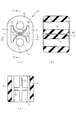
- FIG. 1A is a front view of the insulator 1 in the first embodiment
- FIG. 1B is a cross-sectional view of the insulator 1 taken along the line Ib-Ib in FIG. 1A
- FIG. 2 is a cross-sectional view of the insulator 1 taken along the line Ic-Ic in FIG.
- the insulator 1 is a substantially oval member when viewed from the front, and is integrally formed of a rubber-like elastic body having self-lubricating properties.
- a rubber-like elastic body having a self-lubricating property a rubber-like elastic body such as a fatty acid amide that bleeds on the surface of the rubber-like elastic body to reduce the friction coefficient of the surface and exhibit lubricity is used.
- Insulators 11, 21, 31, 41, 51, 61, 71, 81, 91, and 101, which will be described later, are also integrally formed from a rubber-like elastic body having self-lubricating properties.
- the insulator 1 includes a first part 2 attached to a vehicle body (not shown) side, a second part 4 attached to an exhaust pipe (not shown), and a pair of first parts 2 and the second part 4 connected to each other. And a connecting portion 6.
- the first portion 2 is formed with a circular first mounting hole 3, and the second portion 4 is formed with a circular second mounting hole 5.
- a pin (not shown) attached to the vehicle body is inserted into the first attachment hole 3, and a pin (not shown) attached to an exhaust pipe extending from the engine (not shown) is inserted into the second attachment hole 5. .
- the exhaust pipe includes a silencer and an exhaust gas purification device connected to the exhaust pipe.
- the first portion 2 and the second portion 4 are spaced apart from each other by a pair of connecting portions 6 formed with inner stopper surfaces 6a facing inward.
- the first stopper surface 2a and the second stopper surface 4a facing each other are formed on the first portion 2 and the second portion 4, respectively.
- the first stopper surface 2a is a surface formed in a flat surface shape and intersects the side surface 2b formed in a flat surface shape perpendicularly.
- the side surface 2b is opposed to the flat inner stopper surface 6a formed in the connecting portion 6 with a gap.
- the second stopper surface 4a is a surface formed in a curved surface shape (semi-cylindrical shape) which is a part of the cylindrical side surface (substantially half a circle), and the end portion 4b formed in a concave shape is connected to both side edges.
- a portion near the end portion 4b (a part of the cylindrical side surface) faces the flat inner surface stopper surface 6a formed in the connecting portion 6 with a gap.
- the first portion 2, the second portion 4 and the connecting portion 6 expand and contract vertically to absorb the vibration.
- the 1st part 2 and the 2nd part 4 are comprised from the rubber-like elastic body which has a self-lubricating property
- the internal peripheral surface of the 1st mounting hole 3 and the 2nd mounting hole 5 has a self-lubricating property. ing.
- noise generated when the pin (not shown) inserted into the first mounting hole 3 or the second mounting hole 5 and the inner peripheral surface of the first mounting hole 3 or the second mounting hole 5 are rubbed. Can be suppressed.
- the first stopper surface 2a and the second stopper surface 4a come into contact with each other, and excessive deformation of the insulator 1 is suppressed. Since the second stopper surface 4a is formed in a part of the curved shape of the cylindrical side surface, nonlinear characteristics are given to the first portion 2 and the second portion 4 when the first stopper surface 2a and the second stopper surface 4a come into contact with each other. Can be given.
- the area in contact with the first stopper surface 2a gradually increases along the circumferential direction of the second stopper surface 4a (cylindrical side surface). Since the close contact region expands from the center of the second stopper surface 4a along the circumferential direction of the cylindrical side surface, it is possible to suppress the air from being trapped between the first stopper surface 2a and the second stopper surface 4a. As a result, abnormal noise (noise) generated at the time of contact can be reduced.
- the first portion 2 and the second portion 4 can have nonlinear characteristics. That is, due to the deformation of the first stopper surface 2a and the second stopper surface 4a, the area in contact with the first stopper surface 2a is gradually reduced along the circumferential direction of the second stopper surface 4a (cylindrical side surface). Since the contact area is narrowed along the circumferential direction of the cylindrical side surface from both sides of the second stopper surface 4a, it is possible to reduce abnormal noise generated at the time of attachment / detachment compared to the case where the contacted flat surfaces are attached / detached at a stretch. .
- the second stopper surface 4a is formed in a curved surface shape that is a part of the side surface of the cylinder, the first stopper surface 2a and the second stopper surface 4a are in contact with each other as compared with a protrusion in which a part of the flat surface is raised.
- the stress at the time (during compression deformation) can be relieved. Therefore, fatigue (plastic flow, so-called sag) can be made less likely to occur than the protrusions where stress is concentrated, and the effect of suppressing abnormal noise can be ensured for a long period of time.
- the first stopper surface 2a By forming the first stopper surface 2a in contact with the second stopper surface 4a into a flat surface, the first stopper surface 2a (plane) and the second stopper surface 4a (curved surface) are in contact. Since the stress can be relaxed as compared with the case where the curved surfaces come into contact with each other, the first portion 2 and the second portion 4 can be hardly fatigued. Therefore, the durability of the insulator 1 can be ensured.
- first portion 2 and the second portion 4 are made of a rubber-like elastic body having self-lubricating surfaces (the first stopper surface 2a and the second stopper surface 4a), the first stopper surface 2a and the second portion 4 When the stopper surface 4a comes into contact with the stopper surface, it is possible to suppress noise generated by rubbing each other.
- the connecting portion 6 bends and the first portion 2 and the second portion 4 are displaced relative to each other in the lateral direction (the left-right direction in FIG. 1A).
- the side surface 2b, the inner stopper surface 6a, the second stopper surface 4a, and the inner stopper surface 6a come into contact with each other, and excessive deformation of the connecting portion 6 is suppressed.
- the second stopper surface 4a is formed in a part of the curved shape of the cylindrical side surface, the second portion 4 and the connecting portion 6 have non-linear characteristics when the second stopper surface 4a and the inner stopper surface 6a come into contact with each other. Can be given.
- the area in contact with the inner stopper surface 6a gradually increases along the circumferential direction of the second stopper surface 4a (cylindrical side surface). Since the close contact region expands along the circumferential direction of the cylindrical side surface of the second stopper surface 4a, it is possible to prevent air from being trapped between the inner stopper surface 6a and the second stopper surface 4a. As a result, it is possible to reduce abnormal noise generated at the time of contact.
- the second portion 4 and the connecting portion 6 can be provided with nonlinear characteristics. That is, at the time of separation / attachment, the area in contact with the inner stopper surface 6a gradually decreases along the circumferential direction of the second stopper surface 4a (cylindrical side surface). Unlike the case where the closely contacted flat surfaces are separated from each other at once, the contact region is narrowed along the circumferential direction of the cylindrical side surface of the second stopper surface 4a.
- the second stopper surface 4a is formed in a part of the curved shape of the cylindrical side surface, and the end portion 4b formed in a concave shape is connected to both side edges, so that the curvature of the end portion 4b is set to the side surface 2b of the first portion 2.
- the inner stopper surface 6a can be made smaller than the terminal end portion.
- the connecting portion 6 is made of a rubber-like elastic body having a self-lubricating surface (inner stopper surface 6a), abnormal noise generated by rubbing each other when the inner stopper surface 6a and the side surface 2b come into contact with each other. Can be suppressed. Similarly, when the inner stopper surface 6a and the second stopper surface 4a come into contact with each other, it is possible to suppress noise generated by rubbing each other.
- FIG. 2A is a front view of the insulator 11 in the second embodiment
- FIG. 2B is a cross-sectional view of the insulator 11 taken along the line IIb-IIb in FIG. 2A.
- the insulator 11 has a plurality of protrusions 12 formed on a part of the inner stopper surface 6a facing the side surface 2b of the first portion 2.
- the protrusion 12 is a portion protruding toward the side surface 2b of the first portion 2, and as shown in FIG. 2B, the second stopper surface 4a (part of the cylindrical side surface) is axially (see FIG. b) It is provided over the entire length of the inner stopper surface 6a in parallel with the left-right direction).
- FIG. 3A is a front view of the insulator 21 according to the third embodiment
- FIG. 3B is a cross-sectional view of the insulator 21 taken along the line IIIb-IIIb in FIG. 3A
- FIG. 4 is a cross-sectional view of the insulator 21 taken along the line IIIc-IIIc in FIG.
- both the first stopper surface 22a and the second stopper surface 4a come into contact with each other, and excessive deformation of the insulator 21 is suppressed. Since both the first stopper surface 22a and the second stopper surface 4a are formed in a curved surface shape (semi-cylindrical shape) of a part of the cylindrical side surface (substantially a half circumference), the first stopper surface 22a and the second stopper surface 4a.
- the first portion 22 and the second portion 4 can have a non-linear characteristic at the time of contact.
- the areas of close contact with each other gradually increase along the circumferential direction of the first stopper surface 22a and the second stopper surface 4a (cylindrical side surface). Since the close contact region expands from the center of the first stopper surface 22a and the second stopper surface 4a along the circumferential direction of the cylindrical side surface, air is confined between the first stopper surface 22a and the second stopper surface 4a. Can be prevented. Since both the first stopper surface 22a and the second stopper surface 4a are formed in a curved surface shape of a part of the cylindrical side surface, air is contained more than in the case where one stopper surface is formed in a flat surface shape. The effect which prevents can be improved. As a result, it is possible to improve the effect of reducing abnormal noise generated at the time of contact.
- the first stopper surface 22a and the second stopper surface 4a that are in close contact with each other are detached, the first stopper surface 22a and the second stopper surface 4a are deformed so that the circumference of the first stopper surface 22a and the second stopper surface 4a (cylindrical side surface).
- the area that adheres to each other along the direction gradually decreases. Since the contact area is narrowed from both sides of the first stopper surface 22a and the second stopper surface 4a along the circumferential direction of the cylindrical side surface, it is separated from the case where one stopper surface is formed in a flat surface shape. The noise reduction effect that occurs when wearing can be improved.
- the first stopper surface 22a is formed in a curved surface shape that is a part of the cylindrical side surface, the inner stopper surface 6a (flat surface) and the first stopper surface 22a (part of the cylindrical side surface) are in contact with and detached from each other. You can reduce the noise during the time.
- the first portion 22 and the second portion 4 are made of a rubber-like elastic body having self-lubricating surfaces (the first stopper surface 22a and the second stopper surface 4a). When the stopper surface 4a comes into contact with the stopper surface, it is possible to suppress noise generated by rubbing each other.
- FIG. 4th Embodiment demonstrates the case where a protrusion (1st protrusion 32) is formed in the 2nd stopper surface 4a of the insulator 1 (refer FIG. 1) demonstrated in 1st Embodiment.
- symbol is attached
- 4A is a front view of the insulator 31 according to the fourth embodiment
- FIG. 4B is a cross-sectional view of the insulator 31 taken along the line IVb-IVb in FIG. 4A.
- FIG. 4 is a cross-sectional view of the insulator 31 taken along the line IVc-IVc in FIG.
- the insulator 31 has a first protrusion 32 provided on a part (top) of the second stopper surface 4a closest to the first stopper surface 2a.
- the first protrusion 32 has a semi-cylindrical cross-sectional shape with a curvature larger than that of the second stopper surface 4a, and is parallel to the axial direction of the second stopper surface 4a (cylindrical side surface) (FIG. 4 (b) left-right direction). While extending, it is formed in a ridge shape protruding toward the opposing first stopper surface 2a.
- the first protrusion 32 is provided over substantially the entire length of the second stopper surface 4a.
- the first protrusion 32 When a large vertical compression force acts on the insulator 31, the first protrusion 32 first comes into contact with the first stopper surface 2a. After the first protrusion 32 is crushed, the first stopper surface 22a and the second stopper surface 4a come into close contact with each other. Since the first protrusion 32 has a larger curvature than the second stopper surface 4a, the first stopper surface 2a and the first protrusion 32 are compared with the case where the first stopper surface 2a and the second stopper surface 4a contact each other. It is difficult to keep air in between. Therefore, the effect of suppressing abnormal noise (noise) generated when the first stopper surface 2a and the second stopper surface 4a come into contact with each other can be improved.
- abnormal noise noise
- the connecting portion 6 When a force in the rotation (pitch) direction about the left and right (left and right in FIG. 4A) is input to the insulator 31, the connecting portion 6 is twisted about the left and right. Since the first protrusion 32 is provided over substantially the entire length of the second stopper surface 4a, the first protrusion 32 can be interposed before the first stopper surface 2a and the second stopper surface 4a come into close contact with each other. . Therefore, even when the connecting portion 6 is twisted by pitching, it is possible to improve the effect of suppressing abnormal noise generated when the first stopper surface 2a and the second stopper surface 4a come into contact with each other.
- the first protrusion 32 is made of a rubber-like elastic body having a self-lubricating surface, when the first stopper surface 2a and the first protrusion 32 come into contact with each other, abnormal noise generated by rubbing each other is generated. Can be suppressed.
- FIG. 5A is a front view of the insulator 41 in the fifth embodiment
- FIG. 5B is a cross-sectional view of the insulator 41 taken along the line Vb-Vb in FIG. 5A
- FIG. 6 is a cross-sectional view of the insulator 41 taken along the line Vc-Vc in FIG.
- the insulator 41 has a first protrusion 32 on a part (top) of the second stopper surface 4a closest to the first stopper surface 22a.
- FIG. 6A is a front view of the insulator 51 in the sixth embodiment
- FIG. 6B is a cross-sectional view of the insulator 51 taken along the line VIIb-VIIb of FIG. 6A.
- the insulator 51 is provided with a first protrusion 52 on a part (lower part) of the first stopper surface 22a closest to the second stopper surface 4a.
- the first protrusion 52 has a semi-cylindrical cross-sectional shape having a larger curvature than the first stopper surface 22a, and is parallel to the axial direction of the first stopper surface 22a (cylindrical side surface) (FIG. 6B, left-right direction). While extending, it is formed in a ridge shape projecting toward the opposing second stopper surface 4a.
- the first protrusion 52 is provided over substantially the entire length of the first stopper surface 22a while facing the first protrusion 32 provided on the second stopper surface 4a.
- the first protrusions 32 and 52 When a large vertical compression force acts on the insulator 51, the first protrusions 32 and 52 first come into contact with each other. After the first protrusions 32 and 52 are crushed, the first stopper surface 22a and the second stopper surface 4a come into close contact with each other. Since the first protrusion 52 has a larger curvature than the first stopper surface 22a, air is sealed between the first protrusions 32 and 52 as compared with the case where the first stopper surface 2a and the first protrusion 32 abut. Can be difficult Therefore, the effect of suppressing abnormal noise generated when the first stopper surface 22a and the second stopper surface 4a are brought into contact with each other can be improved.
- the first protrusion 52 is made of a rubber-like elastic body having a self-lubricating surface, it is possible to suppress noise generated by rubbing each other when the first protrusions 32 and 52 come into contact with each other.
- FIG. 7th Embodiment demonstrates the case where a protrusion (2nd protrusion 62) is formed in the 2nd stopper surface 4a of the insulator 31 (refer FIG. 4) demonstrated in 4th Embodiment.
- symbol is attached
- FIG. 7A is a front view of the insulator 61 in the seventh embodiment
- FIG. 7B is a cross-sectional view of the insulator 61 taken along the line VIIb-VIIb in FIG. 7A.
- the insulator 61 is provided with a second protrusion 62 on the second stopper surface 4a that intersects with the first protrusion 32 provided on the second stopper surface 4a.
- the second protrusion 62 has a protrusion height from the second stopper surface 4 a at a portion intersecting the first protrusion 32, so that the first protrusion 32 has a protrusion height. It is set to be the same as the protruding height.
- the second projecting portion 62 extends perpendicular to the axial direction (vertical direction in FIG. 7C) of the second stopper surface 4a (cylindrical side surface) and faces the first.
- the 2nd protrusion 62 is located in the center of the axial direction of the 2nd stopper surface 4a, and is provided over substantially the full length of the circumferential direction of the 2nd stopper surface 4a.
- the protrusion height of the second protrusion 62 from the second stopper surface 4a at both end portions in the circumferential direction gradually decreases toward the end portion 4b, and the protrusion height at the end in the circumferential direction is set to zero. .
- the operation of the insulator 61 when a large vertical compression force is applied is the same as that of the insulator 31 in the fourth embodiment, the description thereof is omitted. According to this insulator 61, the same operation and effect as the insulator 31 in the fourth embodiment can be realized.
- the connecting portion 6 When a force in the rotation (roll) direction around the front and rear (perpendicular to FIG. 7A) is input to the insulator 61, the connecting portion 6 is twisted about the front and rear. Since the 2nd protrusion 62 is provided over the full length of the circumferential direction of the 2nd stopper surface 4a, the 2nd protrusion 62 is interposed before the 1st stopper surface 2a and the 2nd stopper surface 4a contact
- the protrusion height of the second protrusion 62 from the second stopper surface 4a at both end portions in the circumferential direction gradually decreases toward the end portion 4b, and the protrusion height at the end in the circumferential direction is set to zero. .
- a load is applied to the second protrusion 62 (particularly the end in the circumferential direction). It can be difficult to input. This makes it difficult to cause the second protrusion 62 to plastically flow (fatigue), and thus the life of the second protrusion 62 can be extended.
- the second protrusion 62 is made of a rubber-like elastic body having a self-lubricating surface, when the first stopper surface 2a and the second protrusion 62 come into contact with each other, noise generated by rubbing each other is generated. Can be suppressed.
- FIG. 8A is a front view of the insulator 71 in the eighth embodiment
- FIG. 8B is a cross-sectional view of the insulator 71 taken along the line VIIIb-VIIIb in FIG. 8A.
- the insulator 71 is provided with a second protrusion 72 on the second stopper surface 4a that intersects the first protrusion 32 provided on the second stopper surface 4a.
- the second protrusion 72 has a protrusion height from the second stopper surface 4 a at a portion intersecting the first protrusion 32, so that the first protrusion 32 has a protrusion height. It is set to be the same as the protruding height.
- the second protrusion 72 extends in a direction perpendicular to the axial direction (vertical direction in FIG. 8C) of the second stopper surface 4a (cylindrical side surface) and faces the first.
- the 2nd protrusion 72 is located in the center of the axial direction of the 2nd stopper surface 4a, and is provided over substantially the full length of the circumferential direction of the 2nd stopper surface 4a. As for the 2nd protrusion 72, the edge part 72a of the both sides of the circumferential direction protrudes toward the inner side stopper surface 6a from the 2nd stopper surface 4a.
- the operation of the insulator 71 when a large vertical compression force or rotational (roll) direction force is applied is the same as that of the insulator 61 in the seventh embodiment, the description thereof is omitted. According to this insulator 71, the same operation and effect as those of the insulator 61 in the seventh embodiment can be realized.
- the second protrusion 72 has end portions 72a on both sides in the circumferential direction protruding from the second stopper surface 4a toward the inner stopper surface 6a.
- the surface of the second protrusion 72 is made of a rubber-like elastic body having self-lubricating properties, when the first stopper surface 2a and the second protrusion 72 come into contact with each other or when the inner stopper surface 6a and the second protrusion 72 are in contact with each other.
- the projecting portion 72 (end portion 72a) comes into contact, abnormal noise generated by rubbing each other can be suppressed.
- FIG. 9A is a front view of an insulator 81 according to the ninth embodiment
- FIG. 9B is a cross-sectional view of the insulator 81 taken along the line IXb-IXb of FIG. 9A.
- FIG. 10 is a cross-sectional view of the insulator 81 taken along the line IXc-IXc in FIG.
- the insulator 81 has a second protrusion 62 that intersects the first protrusion 32 provided on the second stopper surface 4a on the second stopper surface 4a. It has been. Thereby, the effect
- FIG. 10A is a front view of the insulator 91 according to the tenth embodiment
- FIG. 10B is a cross-sectional view of the insulator 91 taken along the line Xb-Xb in FIG. 10A
- FIG. 11 is a cross-sectional view of the insulator 91 taken along line Xc-Xc in FIG.
- the insulator 91 is provided with a first protrusion 52 on a part of the first stopper surface 22a closest to the second stopper surface 4a.
- the first protrusion 52 has a semi-cylindrical cross-sectional shape having a curvature larger than that of the first stopper surface 22a, and is parallel to the axial direction of the first stopper surface 22a (columnar side surface) (FIG. 10B, left-right direction). While extending, it is formed in a ridge shape projecting toward the opposing second stopper surface 4a.
- the first protrusion 52 is provided over substantially the entire length of the first stopper surface 22a while facing the first protrusion 32 provided on the second stopper surface 4a.
- a second protrusion 92 that intersects the first protrusion 52 is provided on the first stopper surface 22a.
- the second protrusion 92 has a protrusion height from the first stopper surface 22 a at a portion intersecting the first protrusion 52. It is set to be the same as the protruding height.
- the second protrusion 92 extends toward the opposing second stopper surface 4a while extending perpendicular to the axial direction of the first stopper surface 22a (cylindrical side surface) (FIG. 10A, the direction perpendicular to the paper surface). It is formed in a ridge shape.
- the second protrusion 92 is positioned at the center of the first stopper surface 22a in the axial direction, and is opposed to the second protrusion 62 provided on the second stopper surface 4a, and is substantially in the circumferential direction of the first stopper surface 22a. It is provided over the entire length.
- the protruding height from the first stopper surface 22a at both ends in the circumferential direction gradually decreases toward the terminal end 22b, and the protruding height at the end in the circumferential direction is set to zero. .
- the connecting portion 6 When a large compressive force in the roll direction acts on the insulator 91, the connecting portion 6 is twisted about the front and rear (FIG. 10 (a) perpendicular to the paper surface). Since the second protrusions 62 and 92 are provided over substantially the entire length in the circumferential direction of the first stopper surface 22a and the second stopper surface 4a, respectively, the first stopper surface 22a and the second stopper surface 4a are in close contact with each other. The second protrusions 62 and 92 can be interposed in front. Therefore, even when the connecting portion 6 is twisted by rolling, it is possible to improve the effect of suppressing abnormal noise generated when the first stopper surface 22a and the second stopper surface 4a come into contact with each other.
- the second protrusion 92 is formed of a rubber-like elastic body having a self-lubricating surface, the second protrusions 62 and 92 are formed when the second stopper surface 4a and the second protrusion 92 come into contact with each other. Abnormal noise generated by rubbing each other when they come into contact with each other can be suppressed.
- FIG. 11A is a front view of the insulator 101 in the eleventh embodiment, and FIG.
- FIG. 11B is a cross-sectional view of the insulator 101 taken along the line XIb-XIb in FIG. 11A.
- FIG. 12 is a cross-sectional view of the insulator 101 taken along the line XIc-XIc in FIG.
- the first portion 2 and the second portion 102 are connected by a pair of connecting portions 6.
- the second portion 102 is formed with a second stopper surface 102a facing the first stopper surface 2a.
- the second stopper surface 102a is a surface formed in a flat surface shape and intersects the side surface 102b formed in a flat surface shape perpendicularly.
- the side surface 102b faces the flat inner stopper surface 6a formed in the connecting portion 6 with a gap.
- the first portion 2 and the second portion 102 are made of a rubber-like elastic body having self-lubricating properties, pins inserted into the first mounting hole 3 and the second mounting hole 5 (see FIG. (Not shown) and noise generated when the first mounting hole 3 and the inner peripheral surface of the second mounting hole 5 are rubbed.
- first portion 2 and the second portion 102 are made of a rubber-like elastic body having self-lubricating surfaces (the first stopper surface 2a and the second stopper surface 102a), the first stopper surface 2a and the second portion 102 When the stopper surface 102a comes into contact with the stopper surface 102a, it is possible to suppress noise generated by rubbing each other. Further, since the connecting portion 6 is made of a rubber-like elastic body having a self-lubricating surface (inner stopper surface 6a), the inner stopper surface 6a and the side surfaces 2b and 102b rub against each other. Noise can be suppressed.
- the present invention has been described above based on the embodiments. However, the present invention is not limited to the above embodiments, and various improvements and modifications can be made without departing from the spirit of the present invention. It can be easily guessed. For example, the entirety of the insulators 1, 11, 21, 31, 41, 51, 61, 71, 81, 91, 101, the shape of each part, the shape and quantity of the protrusions 12 can be appropriately set.
- the case where the overall shape of the insulators 1, 11, 21, 31, 41, 51, 61, 71, 81, 91, 101 is formed in a substantially oval shape when viewed from the front is described.
- first mounting holes 3 and the second mounting holes 5 are formed in the first portions 2 and 22 and the second portions 4 and 102, respectively. It is not limited to.
- shape and quantity of the first mounting hole 3 and the second mounting hole 5 can be appropriately set according to the shape and quantity of brackets and pins attached to the vehicle body and the exhaust pipe.
- the case where the second stopper surface 4a of the second portion 4 is necessarily formed in a curved shape that is a part of the cylindrical side surface has been described. It is not something that can be done. It is naturally possible to form the first stopper surface 22a of the first portion 22 in a curved shape that is a part of the cylindrical side surface, and form the second stopper surface of the second portion in various shapes such as a flat surface. Also in this case, the first stopper surface 22a of the first portion 22 is formed in a curved surface shape that is a part of the cylindrical side surface, so that the first stopper surface and the second stopper when a large vertical compressive force acts on the insulator. Abnormal noise at the time of contact and separation of the stopper surface can be prevented.
- the second protrusions 62, 72, and 92 when the second protrusions 62, 72, and 92 are provided, the case where the first protrusions 32 and 52 that intersect with the second protrusions 62, 72, and 92 are necessarily provided is described. It is not limited to this. Of course, it is possible to omit the first protrusions 32 and 52 and provide the second protrusions 62, 72 and 92. By providing the second protrusions 62, 72, and 92, it is possible to improve the effect of suppressing abnormal noise when a large compressive force in the roll direction acts on the insulator.
- the protrusion 12 is provided on the inner stopper surface 6a facing the side surface 2b of the first portion 2 formed in a flat surface shape, but the present invention is not necessarily limited thereto.
- the protrusions 12 can improve the effect of suppressing abnormal noise when the second stopper surface 4a (cylindrical side surface) and the inner stopper surface 6a abut.
- the insulators 1, 11, 21, 31, 41, 51, 61, 71, 81, 91, 101 are formed of different materials (a plurality of types of materials are bonded in the forming step). It is possible to manufacture it by the integration method.
- the first stopper surfaces 2a and 22a (first portion 2 and 22) and the second stopper surface 4a (second portion 2) are made of different materials, so that the first stopper surfaces 2a and 22a and the second stopper surface are made of different materials. It is possible to enhance the effect of suppressing abnormal noise that occurs when 4a abuts.
- the case where the insulators 1, 11, 21, 31, 41, 51, 61, 71, 81, 91, 101 are integrally molded from a rubber-like elastic body having self-lubricating properties has been described.
- the inner peripheral surfaces of the first mounting hole 3 and the second mounting hole 5 and the periphery thereof can be formed of a rubber-like elastic body having self-lubricating properties by molding different materials. Thereby, it is possible to suppress noise generated by rubbing a pin (not shown) inserted into the first mounting hole 3 or the second mounting hole 5 and the inner peripheral surface of the first mounting hole 3 or the second mounting hole 5. .
- first parts 2 and 22 and the second parts 4 and 102 with a rubber-like elastic body having self-lubricating property by molding different materials. Thereby, it is possible to suppress noise generated by rubbing a pin (not shown) inserted into the first mounting hole 3 or the second mounting hole 5 and the inner peripheral surface of the first mounting hole 3 or the second mounting hole 5. In addition to this, when the first stopper surfaces 2a and 22a and the second stopper surfaces 4a and 102a come into contact with each other, it is possible to suppress noise generated by rubbing.
- Second protrusion 1, 11, 21, 31, 41, 51, 61, 71, 81, 91, 101 Insulator 2, 22 First part 2a, 22a First stopper surface 3 First mounting hole 4, 102 Second part 4a, 102a First 2 Stopper surface 5 Second mounting hole 6 Connecting portion 6a Inner stopper surface 32, 52 First protrusion 62, 72, 92 Second protrusion
Abstract
異音を抑制できるインシュレータを提供する。車体側に係合する第1取付孔(3)が第1部分(2)に形成され、排気管側に係合する第2取付孔(5)が、第1部分(2)と離隔して配置される第2部分(4)に形成される。第1部分(2)及び第2部分(4)は一対の連結部(6)により連結される。第1部分(2)及び第2部分(4)は、少なくとも第1取付孔(3)及び第2取付孔(5)の内周面が、自己潤滑性を有するゴム状弾性体から構成されている。その結果、第1取付孔(3)及び第2取付孔(5)の内周面の自己潤滑性によって、第1取付孔(3)や第2取付孔(5)とピンとが擦れるときに 生じる異音を抑制できる。
Description
本発明は排気管を弾性支持するゴム状弾性体製のインシュレータに関し、特に異音を抑制できるインシュレータに関するものである。
自動車のエンジンの発生する振動を排気管から車体へ伝えないようにするため、車体と排気管との間にゴム状弾性体製のインシュレータが介設される(特許文献1)。特許文献1に開示される技術では、インシュレータは、第1取付孔が形成される第1部分と、第2取付孔が形成される第2部分と、それら第1部分および第2部分を連結する一対の連結部とを備えている。車体に取り付けられたピンを第1取付孔に挿入し、排気管に取り付けられたピンを第2取付孔に挿入することで、インシュレータを介して排気管が車体に吊り下げ支持される。
しかしながら上述した従来の技術では、エンジンの振動や車両の走行に伴う排気管の振動によってインシュレータが振動すると、第1取付孔や第2取付孔とピンとが擦れて異音が生じるという問題点がある。
本発明は上述した問題点を解決するためになされたものであり、異音を抑制できるインシュレータを提供することを目的としている。
この目的を達成するために請求項1記載のインシュレータによれば、車体側に係合する第1取付孔が第1部分に形成され、排気管側に係合する第2取付孔が、第1部分と離隔して配置される第2部分に形成される。ゴム状弾性体製のインシュレータにより排気管が弾性支持される。互いに内側を向く内側ストッパ面が、第1部分および第2部分を連結する一対の連結部に形成される。第1部分および第2部分は、連結部に形成された内側ストッパ面と間をあけて、それぞれ第1ストッパ面および第2ストッパ面が形成される。第1部分および第2部分は、少なくとも第1取付孔および第2取付孔の内周面が、自己潤滑性を有するゴム状弾性体から構成されている。その結果、第1取付孔および第2取付孔の内周面の自己潤滑性によって、第1取付孔や第2取付孔とピンとが擦れるときに生じる異音を抑制できる効果がある。
請求項2記載のインシュレータによれば、全体が自己潤滑性を有するゴム状弾性体から構成されている。ここで、車両の走行に伴ってインシュレータに大きな外力が入力されると、第1ストッパ面と第2ストッパ面とが相互に当接して、インシュレータの過大な変形が抑制される。請求項1の効果に加え、第1ストッパ面と第2ストッパ面とが擦れるときに生じる異音を、ゴム状弾性体の自己潤滑性によって抑制できる効果がある。
請求項3記載のインシュレータによれば、互いに対向する第1ストッパ面および第2ストッパ面は、少なくとも一方が、円柱側面の一部である曲面形状に形成されている。その結果、円柱側面の一部である曲面形状に形成された第1ストッパ面(第1部分)または第2ストッパ面(第2部分)に、当接時および離着時の非線形特性をもたせることができる。よって、請求項1又は2の効果に加え、ストッパ面の当接時および離着時に生じる異音を抑制できる効果がある。
請求項4記載のインシュレータによれば、円柱側面の一部である曲面形状に形成された第1ストッパ面または第2ストッパ面は、第1ストッパ面または第2ストッパ面の軸方向と平行に延在する突条状の第1突部を備えている。第1突部は、対向するストッパ面へ向かって突出するので、第1ストッパ面および第2ストッパ面の当接時および離着時の非線形特性をさらに顕著にすることができる。よって、請求項3の効果に加え、ストッパ面の当接時または離着時に生じる異音の抑制効果を向上できる。
また、第1突部は、第1ストッパ面または第2ストッパ面の軸方向と平行に延在するので、第1ストッパ面および第2ストッパ面が軸方向へ相対変位した場合も、第1突部による非線形特性を得ることができる効果がある。
請求項5記載のインシュレータによれば、円柱側面の一部である曲面形状に形成された第1ストッパ面または第2ストッパ面は、第1ストッパ面または第2ストッパ面の軸方向と直交して延在する突条状の第2突部を備えている。第2突部は、対向するストッパ面へ向かって突出するので、第1ストッパ面および第2ストッパ面の当接時および離着時の非線形特性をさらに顕著にすることができる。よって、請求項3又は4の効果に加え、ストッパ面の当接時または離着時に生じる異音の抑制効果を向上できる。
また、第2突部は、第1ストッパ面または第2ストッパ面の軸方向と直交して延在するので、第1ストッパ面および第2ストッパ面が軸直角方向へ相対変位した場合も、第2突部による非線形特性を得ることができる効果がある。
以下、本発明の好ましい実施の形態について添付図面を参照して説明する。図1を参照して本発明の第1実施の形態におけるインシュレータ1について説明する。図1(a)は第1実施の形態におけるインシュレータ1の正面図であり、図1(b)は図1(a)のIb-Ib線におけるインシュレータ1の断面図であり、図1(c)は図1(a)のIc-Ic線におけるインシュレータ1の断面図である。
図1(a)から図1(c)に示すように、インシュレータ1は正面視が略長円形状の部材であり、自己潤滑性を有するゴム状弾性体から一体に構成されている。自己潤滑性を有するゴム状弾性体としては、脂肪酸アミド等の潤滑剤がゴム状弾性体の表面にブリードして、表面の摩擦係数を低減して潤滑性を発揮するものが用いられる。なお、後述するインシュレータ11,21,31,41,51,61,71,81,91,101も、自己潤滑性を有するゴム状弾性体から一体に構成されている。
インシュレータ1は、車体(図示せず)側に取り付けられる第1部分2と、排気管(図示せず)に取り付けられる第2部分4と、第1部分2及び第2部分4を連結する一対の連結部6とを備えている。第1部分2は円形の第1取付孔3が形成され、第2部分4は円形の第2取付孔5が形成される。車体に取り付けられたピン(図示せず)を第1取付孔3に挿入し、エンジン(図示せず)から延びる排気管に取り付けられたピン(図示せず)を第2取付孔5に挿入する。これにより、インシュレータ1を介して排気管が車体に吊り下げ支持される。なお、排気管は、それに接続される消音器や排気ガス浄化装置を含むものである。
第1部分2及び第2部分4は、互いに内側を向く内側ストッパ面6aが形成された一対の連結部6によって互いに離隔して配置される。その結果、互いに対向する第1ストッパ面2a及び第2ストッパ面4aが、第1部分2及び第2部分4にそれぞれ形成される。第1ストッパ面2aは、平坦面状に形成される面であり、平坦面状に形成された側面2bと垂直に交わる。側面2bは、連結部6に形成された平坦面状の内側ストッパ面6aと隙間をあけて対向する。
第2ストッパ面4aは、円柱側面の一部(ほぼ半周分)である曲面形状(半円柱状)に形成される面であり、凹面状に形成された終端部4bと両側縁が連なる。第2ストッパ面4aは、終端部4b近くの部分(円柱側面の一部)が、連結部6に形成された平坦面状の内側ストッパ面6aと隙間をあけて対向する。
インシュレータ1によれば、エンジンの振動や車両の走行に伴って排気管(図示せず)が上下動すると、第1部分2、第2部分4及び連結部6が上下に伸縮して振動を吸収する。第1部分2及び第2部分4は自己潤滑性を有するゴム状弾性体から構成されているので、少なくとも第1取付孔3及び第2取付孔5の内周面は、自己潤滑性を有している。その結果、第1取付孔3や第2取付孔5に挿入されたピン(図示せず)と、第1取付孔3や第2取付孔5の内周面とが擦れるときに生じる異音を抑制できる。
インシュレータ1に大きな上下の圧縮力が作用すると、第1ストッパ面2a及び第2ストッパ面4aが相互に当接して、インシュレータ1の過大な変形が抑制される。第2ストッパ面4aは円柱側面の一部の曲面形状に形成されているので、第1ストッパ面2a及び第2ストッパ面4aの当接時に、第1部分2及び第2部分4に非線形特性をもたせることができる。
即ち、第1ストッパ面2a及び第2ストッパ面4aの変形により、第2ストッパ面4a(円柱側面)の周方向に沿って第1ストッパ面2aに接する面積が次第に大きくなる。第2ストッパ面4aの中央から円柱側面の周方向に沿って密着領域が広がっていくので、第1ストッパ面2aと第2ストッパ面4aとの間に空気が封じ込められることを抑制できる。その結果、当接時に生じる異音(騒音)を軽減できる。
密着した第1ストッパ面2a及び第2ストッパ面4aの離着時にも、第1部分2及び第2部分4に非線形特性をもたせることができる。即ち、第1ストッパ面2a及び第2ストッパ面4aの変形により、第2ストッパ面4a(円柱側面)の周方向に沿って第1ストッパ面2aに接する面積が次第に小さくなる。第2ストッパ面4aの両側から円柱側面の周方向に沿って密着領域が狭められていくので、密着した平坦面同士が一気に離着する場合と比較して、離着時に生じる異音を軽減できる。
第2ストッパ面4aは円柱側面の一部である曲面形状に形成されているので、平坦面の一部が隆起した突起と比較して、第1ストッパ面2a及び第2ストッパ面4aの当接時(圧縮変形時)の応力を緩和できる。そのため、応力が集中する突起と比較して疲労(塑性流動、所謂へたり)を生じ難くすることができ、異音の抑制効果を長期間確保できる。
第2ストッパ面4aと当接する第1ストッパ面2aを平坦面状に形成することで、第1ストッパ面2a(平面)と第2ストッパ面4a(曲面)とが当接することになる。曲面同士が当接する場合と比較して応力を緩和できるので、第1部分2及び第2部分4を疲労し難くできる。よって、インシュレータ1の耐久性を確保できる。
第1部分2及び第2部分4は、表面(第1ストッパ面2a及び第2ストッパ面4a)が自己潤滑性を有するゴム状弾性体から構成されているので、第1ストッパ面2aと第2ストッパ面4aとが当接したときに、互いに擦れて生じる異音を抑制できる。
車体に対して排気管が横揺れすると、連結部6が屈曲して第1部分2と第2部分4とが横方向(図1(a)左右方向)に相対変位する。この相対変位により側面2b及び内側ストッパ面6a、第2ストッパ面4a及び内側ストッパ面6aが相互に当接して、連結部6の過大な変形が抑制される。このとき、第2ストッパ面4aは円柱側面の一部の曲面形状に形成されているので、第2ストッパ面4a及び内側ストッパ面6aの当接時に、第2部分4及び連結部6に非線形特性をもたせることができる。
即ち、内側ストッパ面6aと第2ストッパ面4aとが当接するときには、第2ストッパ面4a(円柱側面)の周方向に沿って内側ストッパ面6aに接する面積が次第に大きくなる。第2ストッパ面4aの円柱側面の周方向に沿って密着領域が広がっていくので、内側ストッパ面6aと第2ストッパ面4aとの間に空気が封じ込められることを防止できる。その結果、当接時に生じる異音を軽減できる。
密着した内側ストッパ面6a及び第2ストッパ面4aの離着時にも、第2部分4及び連結部6に非線形特性をもたせることができる。即ち、離着時は第2ストッパ面4a(円柱側面)の周方向に沿って内側ストッパ面6aに接する面積が次第に小さくなる。密着した平坦面同士が一気に離着する場合とは異なり、第2ストッパ面4aの円柱側面の周方向に沿って密着領域が狭められていくので、離着時に生じる異音を軽減できる。
第2ストッパ面4aは円柱側面の一部の曲面形状に形成されると共に、凹面状に形成された終端部4bと両側縁が連なるので、終端部4bの曲率を、第1部分2の側面2bと内側ストッパ面6aとが連なる終端部と比較して小さくできる。その結果、第1部分2の終端部と比較して、終端部4bに加わる応力を小さくできる(分散できる)。よって、インシュレータ1に加わる外力に起因する亀裂を終端部4bに生じ難くできる。その結果、インシュレータ1の耐久性を高めることができる。
連結部6は、表面(内側ストッパ面6a)が自己潤滑性を有するゴム状弾性体から構成されているので、内側ストッパ面6aと側面2bとが当接したときに、互いに擦れて生じる異音を抑制できる。同様に、内側ストッパ面6aと第2ストッパ面4aとが当接したときに、互いに擦れて生じる異音を抑制できる。
図2を参照して第2実施の形態について説明する。第2実施の形態では、内側ストッパ面6aに凸起12が形成される場合について説明する。なお、第1実施の形態と同一の部分については、同一の符号を付して以下の説明を省略する。図2(a)は第2実施の形態におけるインシュレータ11の正面図であり、図2(b)は図2(a)のIIb-IIb線におけるインシュレータ11の断面図である。
図2(a)に示すようにインシュレータ11は、第1部分2の側面2bと対向する内側ストッパ面6aの一部に複数の凸起12が形成されている。凸起12は、第1部分2の側面2bへ向かって突出する部位であり、図2(b)に示すように、第2ストッパ面4a(円柱側面の一部)の軸方向(図2(b)左右方向)と平行に内側ストッパ面6aの全長に亘って設けられている。
インシュレータ11を用いて車体(図示せず)に弾性支持された排気管(図示せず)が横揺れすると、連結部6が屈曲して第1部分2と第2部分4とが横方向(図2(a)左右方向)に相対変位する。この相対変位により側面2b及び内側ストッパ面6a、第2ストッパ面4a及び内側ストッパ面6aが相互に当接して、連結部6の過大な変形が抑制される。このとき、内側ストッパ面6aに凸起12が設けられているので、側面2b及び内側ストッパ面6aが密着する前に突起12を介在させることができる。凸起12が潰れた後に側面2b及び内側ストッパ面6aが密着するので、側面2b及び内側ストッパ面6a間(平坦面間)に空気を封じ込ませ難くできる。よって、側面2b及び内側ストッパ面6aの当接時に生じる異音を抑制できる。また、凸起12や側面2bの自己潤滑性により、それらが互いに擦れて生じる異音を抑制できる。
ここで、上下(図2(a)上下)を軸にした回転(ヨー)方向の力がインシュレータ11に入力されると、上下を軸にして連結部6が捩じられる。凸起12は内側ストッパ面6aの全長に亘って設けられているので、側面2b及び内側ストッパ面6aが密着する前に突起12を介在させることができる。よって、ヨーイングによって連結部6が捩じられた場合も、側面2b及び内側ストッパ面6aの当接時に生じる異音を抑制できる。
なお、連結部6の内側ストッパ面6aに凸起12が設けられた場合について説明したが、必ずしもこれに限られるものではなく、第1部分2の側面2bに凸起を設けることは当然可能である。この場合も、上記実施の形態と同様の作用・効果を実現できる。
図3を参照して第3実施の形態について説明する。第1及び第2実施の形態では、第1部分2に形成された第1ストッパ面2aが平坦面形状に形成される場合について説明した。これに対し第3実施の形態では、第1部分22に形成された第1ストッパ面22aが円柱側面の一部である曲面形状に形成される場合について説明する。なお、第1実施の形態と同一の部分については、同一の符号を付して以下の説明を省略する。図3(a)は第3実施の形態におけるインシュレータ21の正面図であり、図3(b)は図3(a)のIIIb-IIIb線におけるインシュレータ21の断面図であり、図3(c)は図3(a)のIIIc-IIIc線におけるインシュレータ21の断面図である。
インシュレータ21に大きな上下の圧縮力が作用すると、第1ストッパ面22a及び第2ストッパ面4aが相互に当接して、インシュレータ21の過大な変形が抑制される。第1ストッパ面22a及び第2ストッパ面4aはいずれも円柱側面の一部(ほぼ半周分)の曲面形状(半円柱状)に形成されているので、第1ストッパ面22a及び第2ストッパ面4aの当接時に、第1部分22及び第2部分4に非線形特性をもたせることができる。
即ち、第1ストッパ面22a及び第2ストッパ面4aの変形により、第1ストッパ面22a及び第2ストッパ面4a(円柱側面)の周方向に沿って、互いに密着する面積が次第に大きくなる。第1ストッパ面22a及び第2ストッパ面4aの中央から円柱側面の周方向に沿って密着領域が広がっていくので、第1ストッパ面22aと第2ストッパ面4aとの間に空気が封じ込められることを防止できる。第1ストッパ面22a及び第2ストッパ面4aはいずれも円柱側面の一部の曲面形状に形成されているので、一方のストッパ面が平坦面状に形成される場合と比較して、空気の封じ込めを防ぐ効果を向上できる。その結果、当接時に生じる異音の軽減効果を向上できる。
密着した第1ストッパ面22a及び第2ストッパ面4aの離着時には、第1ストッパ面22a及び第2ストッパ面4aの変形により、第1ストッパ面22a及び第2ストッパ面4a(円柱側面)の周方向に沿って互いに密着する面積が次第に小さくなる。第1ストッパ面22a及び第2ストッパ面4aの両側から円柱側面の周方向に沿って密着領域が狭められていくので、一方のストッパ面が平坦面状に形成される場合と比較して、離着時に生じる異音の軽減効果を向上できる。
第1ストッパ面22aは円柱側面の一部である曲面形状に形成されているので、内側ストッパ面6a(平坦面)及び第1ストッパ面22a(円柱側面の一部)の当接時および離着時の異音を軽減できる。
第1部分22及び第2部分4は、表面(第1ストッパ面22a及び第2ストッパ面4a)が自己潤滑性を有するゴム状弾性体から構成されているので、第1ストッパ面22aと第2ストッパ面4aとが当接したときに、互いに擦れて生じる異音を抑制できる。
図4を参照して第4実施の形態について説明する。第4実施の形態では、第1実施の形態で説明したインシュレータ1(図1参照)の第2ストッパ面4aに突部(第1突部32)が形成される場合について説明する。なお、第1実施の形態と同一の部分については、同一の符号を付して以下の説明を省略する。図4(a)は第4実施の形態におけるインシュレータ31の正面図であり、図4(b)は図4(a)のIVb-IVb線におけるインシュレータ31の断面図であり、図4(c)は図4(a)のIVc-IVc線におけるインシュレータ31の断面図である。
図4(a)に示すようにインシュレータ31は、第1ストッパ面2aに最も近い第2ストッパ面4aの一部(頂部)に第1突部32が設けられている。第1突部32は、第2ストッパ面4aより曲率が大きい半円柱状の断面形状を有し、第2ストッパ面4a(円柱側面)の軸方向(図4(b)左右方向)と平行に延在しつつ、対向する第1ストッパ面2aへ向かって突出する突条状に形成されている。第1突部32は、第2ストッパ面4aのほぼ全長に亘って設けられている。
インシュレータ31に大きな上下の圧縮力が作用すると、第1ストッパ面2aに第1突部32が最初に当接する。第1突部32が潰れた後に第1ストッパ面22a及び第2ストッパ面4aが密着する。第1突部32は第2ストッパ面4aより曲率が大きいので、第1ストッパ面2aと第2ストッパ面4aとが当接する場合と比較して、第1ストッパ面2aと第1突部32との間に空気を封じ込ませ難くできる。よって、第1ストッパ面2a及び第2ストッパ面4aの当接時に生じる異音(騒音)の抑制効果を向上できる。
左右(図4(a)左右)を軸にした回転(ピッチ)方向の力がインシュレータ31に入力されると、左右を軸にして連結部6が捩じられる。第1突部32は第2ストッパ面4aのほぼ全長に亘って設けられているので、第1ストッパ面2a及び第2ストッパ面4aが密着する前に第1突部32を介在させることができる。よって、ピッチングによって連結部6が捩じられた場合も、第1ストッパ面2a及び第2ストッパ面4aの当接時に生じる異音の抑制効果を向上できる。
第1突部32は表面が自己潤滑性を有するゴム状弾性体から構成されているので、第1ストッパ面2aと第1突部32とが当接したときに、互いに擦れて生じる異音を抑制できる。
図5を参照して第5実施の形態について説明する。第5実施の形態では、第3実施の形態で説明したインシュレータ21(図3参照)の第2ストッパ面4aに突部(第1突部32)が形成される場合について説明する。なお、第3及び第4実施の形態と同一の部分については、同一の符号を付して以下の説明を省略する。図5(a)は第5実施の形態におけるインシュレータ41の正面図であり、図5(b)は図5(a)のVb-Vb線におけるインシュレータ41の断面図であり、図5(c)は図5(a)のVc-Vc線におけるインシュレータ41の断面図である。
図5(a)から図5(c)に示すようにインシュレータ41は、第1ストッパ面22aに最も近い第2ストッパ面4aの一部(頂部)に第1突部32が設けられている。これにより、第4実施の形態で説明したインシュレータ31と同様の作用・効果を実現できる。
図6を参照して第6実施の形態について説明する。第6実施の形態では、第5実施の形態で説明したインシュレータ41(図5参照)の第1ストッパ面22aに突部(第1突部52)が形成される場合について説明する。なお、第5実施の形態と同一の部分については、同一の符号を付して以下の説明を省略する。図6(a)は第6実施の形態におけるインシュレータ51の正面図であり、図6(b)は図6(a)のVIIb-VIIb線におけるインシュレータ51の断面図であり、図6(c)は図6(a)のVIIc-VIIc線におけるインシュレータ51の断面図である。
図6(a)に示すようにインシュレータ51は、第2ストッパ面4aに最も近い第1ストッパ面22aの一部(下部)に第1突部52が設けられている。第1突部52は、第1ストッパ面22aより曲率が大きい半円柱状の断面形状を有し、第1ストッパ面22a(円柱側面)の軸方向(図6(b)左右方向)と平行に延在しつつ、対向する第2ストッパ面4aへ向かって突出する突条状に形成されている。第1突部52は、第2ストッパ面4aに設けられた第1突部32と対向しつつ、第1ストッパ面22aのほぼ全長に亘って設けられている。
インシュレータ51に大きな上下の圧縮力が作用すると、第1突部32,52同士が最初に当接する。第1突部32,52が潰れた後に第1ストッパ面22a及び第2ストッパ面4aが密着する。第1突部52は第1ストッパ面22aより曲率が大きいので、第1ストッパ面2aと第1突部32とが当接する場合と比較して、第1突部32,52間に空気を封じ込ませ難くできる。よって、第1ストッパ面22a及び第2ストッパ面4aの当接時に生じる異音の抑制効果を向上できる。
第1突部52は表面が自己潤滑性を有するゴム状弾性体から構成されているので、第1突部32,52同士が当接したときに、互いに擦れて生じる異音を抑制できる。
図7を参照して第7実施の形態について説明する。第7実施の形態では、第4実施の形態で説明したインシュレータ31(図4参照)の第2ストッパ面4aに突部(第2突部62)が形成される場合について説明する。なお、第4実施の形態と同一の部分については、同一の符号を付して以下の説明を省略する。図7(a)は第7実施の形態におけるインシュレータ61の正面図であり、図7(b)は図7(a)のVIIb-VIIb線におけるインシュレータ61の断面図であり、図7(c)は図7(a)のVIIc-VIIc線におけるインシュレータ61の断面図である。
図7(a)に示すようにインシュレータ61は、第2ストッパ面4aに設けられた第1突部32と交差する第2突部62が、第2ストッパ面4aに設けられている。図7(a)及び図7(b)に示すように、第2突部62は、第1突部32と交差する部分の第2ストッパ面4aからの突出高さが、第1突部32の突出高さと同一に設定されている。図7(c)に示すように第2突部62は、第2ストッパ面4a(円柱側面)の軸方向(図7(c)上下方向)と直交して延在しつつ、対向する第1ストッパ面2aへ向かって突出する突条状に形成される。第2突部62は、第2ストッパ面4aの軸方向の中央に位置し、第2ストッパ面4aの周方向のほぼ全長に亘って設けられている。第2突部62は、周方向の両端部分の第2ストッパ面4aからの突出高さが、終端部4bへ向かうにつれて次第に小さくなり、周方向の端部の突出高さが0に設定される。
大きな上下の圧縮力が作用したときのインシュレータ61の動作は、第4実施の形態におけるインシュレータ31と同様なので説明を省略する。このインシュレータ61によれば、第4実施の形態におけるインシュレータ31と同様の作用・効果を実現できる。
前後(図7(a)紙面垂直)を軸にした回転(ロール)方向の力がインシュレータ61に入力されると、前後を軸にして連結部6が捩じられる。第2突部62は第2ストッパ面4aの周方向のほぼ全長に亘って設けられているので、第1ストッパ面2a及び第2ストッパ面4aが密着する前に第2突部62を介在させることができる。よって、ローリングによって連結部6が捩じられた場合も、第1ストッパ面2a及び第2ストッパ面4aの当接時に生じる異音の抑制効果を向上できる。
第2突部62は、周方向の両端部分の第2ストッパ面4aからの突出高さが、終端部4bへ向かうにつれて次第に小さくなり、周方向の端部の突出高さが0に設定される。その結果、車体に対して排気管が横揺れして、第2ストッパ面4aと内側ストッパ面6aとが相互に当接する場合に、第2突部62(特に周方向の端部)に荷重を入力させ難くできる。これにより第2突部62を塑性流動(疲労)させ難くできるので、第2突部62の寿命を長くすることができる。
第2突部62は表面が自己潤滑性を有するゴム状弾性体から構成されているので、第1ストッパ面2aと第2突部62とが当接したときに、互いに擦れて生じる異音を抑制できる。
図8を参照して第8実施の形態について説明する。第8実施の形態では、第7実施の形態で説明したインシュレータ61(図7参照)の第2ストッパ面4aに形成された第2突部62に代えて、第2突部72が形成される場合について説明する。なお、第4実施の形態と同一の部分については、同一の符号を付して以下の説明を省略する。図8(a)は第8実施の形態におけるインシュレータ71の正面図であり、図8(b)は図8(a)のVIIIb-VIIIb線におけるインシュレータ71の断面図であり、図8(c)は図8(a)のVIIIc-VIIIc線におけるインシュレータ71の断面図である。
図8(a)に示すようにインシュレータ71は、第2ストッパ面4aに設けられた第1突部32と交差する第2突部72が、第2ストッパ面4aに設けられている。図8(a)及び図8(b)に示すように、第2突部72は、第1突部32と交差する部分の第2ストッパ面4aからの突出高さが、第1突部32の突出高さと同一に設定されている。図8(c)に示すように第2突部72は、第2ストッパ面4a(円柱側面)の軸方向(図8(c)上下方向)と直交して延在しつつ、対向する第1ストッパ面2aへ向かって突出する突条状に形成される。第2突部72は、第2ストッパ面4aの軸方向の中央に位置し、第2ストッパ面4aの周方向のほぼ全長に亘って設けられている。第2突部72は、周方向の両側の端部72aが、第2ストッパ面4aから内側ストッパ面6aへ向かって突出している。
大きな上下の圧縮力や回転(ロール)方向の力が作用したときのインシュレータ71の動作は、第7実施の形態におけるインシュレータ61と同様なので説明を省略する。このインシュレータ71によれば、第7実施の形態におけるインシュレータ61と同様の作用・効果を実現できる。
第2突部72は、周方向の両側の端部72aが、第2ストッパ面4aから内側ストッパ面6aへ向かって突出している。その結果、車体に対して排気管が横揺れして、第2ストッパ面4aと内側ストッパ面6aとが相互に当接する場合に、第2ストッパ面4a及び内側ストッパ面6aが密着する前に端部72aを介在させることができる。端部72aが潰れた後に第2ストッパ面4a及び内側ストッパ面6aが密着するので、第2ストッパ面4a(円柱側面)及び内側ストッパ面6a間(平坦面間)に空気を封じ込ませ難くできる。よって、第2ストッパ面4a及び内側ストッパ面6aの当接時に生じる異音の抑制効果を向上できる。
第2突部72は表面が自己潤滑性を有するゴム状弾性体から構成されているので、第1ストッパ面2aと第2突部72とが当接したときや、内側ストッパ面6aと第2突部72(端部72a)とが当接したときに、互いに擦れて生じる異音を抑制できる。
図9を参照して第9実施の形態について説明する。第9実施の形態では、第5実施の形態で説明したインシュレータ41(図5参照)の第2ストッパ面4aに突部(第2突部62)が形成される場合について説明する。なお、第5及び第7実施の形態と同一の部分については、同一の符号を付して以下の説明を省略する。図9(a)は第9実施の形態におけるインシュレータ81の正面図であり、図9(b)は図9(a)のIXb-IXb線におけるインシュレータ81の断面図であり、図9(c)は図9(a)のIXc-IXc線におけるインシュレータ81の断面図である。
図9(a)から図9(c)に示すようにインシュレータ81は、第2ストッパ面4aに設けられた第1突部32と交差する第2突部62が、第2ストッパ面4aに設けられている。これにより、第7実施の形態で説明したインシュレータ61と同様の作用・効果を実現できる。
図10を参照して第10実施の形態について説明する。第10実施の形態では、第9実施の形態で説明したインシュレータ81(図9参照)の第1ストッパ面22aに突部(第1突部52及び第2突部92)が形成される場合について説明する。なお、第6及び第7実施の形態と同一の部分については、同一の符号を付して以下の説明を省略する。図10(a)は第10実施の形態におけるインシュレータ91の正面図であり、図10(b)は図10(a)のXb-Xb線におけるインシュレータ91の断面図であり、図10(c)は図10(a)のXc-Xc線におけるインシュレータ91の断面図である。
図10(a)に示すようにインシュレータ91は、第2ストッパ面4aに最も近い第1ストッパ面22aの一部に第1突部52が設けられている。第1突部52は、第1ストッパ面22aより曲率が大きい半円柱状の断面形状を有し、第1ストッパ面22a(円柱側面)の軸方向(図10(b)左右方向)と平行に延在しつつ、対向する第2ストッパ面4aへ向かって突出する突条状に形成されている。第1突部52は、第2ストッパ面4aに設けられた第1突部32と対向しつつ、第1ストッパ面22aのほぼ全長に亘って設けられている。
インシュレータ91は、第1突部52と交差する第2突部92が、第1ストッパ面22aに設けられている。図10(a)及び図10(b)に示すように、第2突部92は、第1突部52と交差する部分の第1ストッパ面22aからの突出高さが、第1突部52の突出高さと同一に設定されている。第2突部92は、第1ストッパ面22a(円柱側面)の軸方向(図10(a)紙面垂直方向)と直交して延在しつつ、対向する第2ストッパ面4aへ向かって突出する突条状に形成される。第2突部92は、第1ストッパ面22aの軸方向の中央に位置し、第2ストッパ面4aに設けられた第2突部62と対向しつつ、第1ストッパ面22aの周方向のほぼ全長に亘って設けられている。第2突部92は、周方向の両端部分の第1ストッパ面22aからの突出高さが、終端部22bへ向かうにつれて次第に小さくなり、周方向の端部の突出高さが0に設定される。
インシュレータ91に大きなロール方向の圧縮力が作用すると、前後(図10(a)紙面垂直)を軸にして連結部6が捩じられる。第2突部62,92は、それぞれ第1ストッパ面22a及び第2ストッパ面4aの周方向のほぼ全長に亘って設けられているので、第1ストッパ面22a及び第2ストッパ面4aが密着する前に第2突部62,92を介在させることができる。よって、ローリングによって連結部6が捩じられた場合も、第1ストッパ面22a及び第2ストッパ面4aの当接時に生じる異音の抑制効果を向上できる。
第2突部92は表面が自己潤滑性を有するゴム状弾性体から構成されているので、第2ストッパ面4aと第2突部92とが当接したときや、第2突部62,92同士が当接したときに、互いに擦れて生じる異音を抑制できる。
図11を参照して第11実施の形態について説明する。第1から第10実施の形態では、第1ストッパ面2a,22a、第2ストッパ面4aの少なくとも一方が円柱側面の一部である曲面形状に形成される場合について説明した。これに対し第11実施の形態では、第1ストッパ面2a及び第2ストッパ面102aがいずれも平坦面状に形成される場合について説明する。なお、第1実施の形態で説明した部分と同一の部分については、同一の符号を付して以下の説明を省略する。図11(a)は第11実施の形態におけるインシュレータ101の正面図であり、図11(b)は図11(a)のXIb-XIb線におけるインシュレータ101の断面図であり、図11(c)は図11(a)のXIc-XIc線におけるインシュレータ101の断面図である。
インシュレータ101は、一対の連結部6によって第1部分2及び第2部分102が連結されている。第2部分102は、第1ストッパ面2aに対向する第2ストッパ面102aが形成されている。第2ストッパ面102aは、平坦面状に形成される面であり、平坦面状に形成された側面102bと垂直に交わる。側面102bは、連結部6に形成された平坦面状の内側ストッパ面6aと隙間をあけて対向する。
インシュレータ101によれば、第1部分2及び第2部分102は自己潤滑性を有するゴム状弾性体から構成されているので、第1取付孔3や第2取付孔5に挿入されたピン(図示せず)と、第1取付孔3や第2取付孔5の内周面とが擦れるときに生じる異音を抑制できる。
第1部分2及び第2部分102は、表面(第1ストッパ面2a及び第2ストッパ面102a)が自己潤滑性を有するゴム状弾性体から構成されているので、第1ストッパ面2aと第2ストッパ面102aとが当接したときに、互いに擦れて生じる異音を抑制できる。さらに、連結部6は、表面(内側ストッパ面6a)が自己潤滑性を有するゴム状弾性体から構成されているので、内側ストッパ面6aと側面2b,102bとが当接したときに、互いに擦れて生じる異音を抑制できる。
以上、実施の形態に基づき本発明を説明したが、本発明は上記実施の形態に何ら限定されるものではなく、本発明の趣旨を逸脱しない範囲内で種々の改良変形が可能であることは容易に推察できるものである。例えば、インシュレータ1,11,21,31,41,51,61,71,81,91,101の全体や各部の形状、凸起12の形状や数量等は適宜設定することが可能である。
上記各実施の形態では、インシュレータ1,11,21,31,41,51,61,71,81,91,101の全体の形状が正面視で略長円形状に形成される場合について説明したが、必ずしもこれに限られるものではない。インシュレータの全体を正面視で略円形状、角丸矩形状、略半円形状等の周知な形状にすることは当然可能である。
上記各実施の形態では、第1部分2,22及び第2部分4,102にそれぞれ一つずつ円形の第1取付孔3、第2取付孔5が形成される場合について説明したが、必ずしもこれに限られるものではない。車体や排気管に取り付けられるブラケットやピンの形状や数量に応じて、第1取付孔3や第2取付孔5の形状や数量を適宜設定することは当然可能である。
上記各実施の形態では、上下方向へ直線状に延びるように一対の連結部6が平板状に形成される場合について説明したが、必ずしもこれに限られるものではなく、連結部6を湾曲板状に形成することは当然可能である。
上記第1実施の形態から第10実施の形態では、第2部分4の第2ストッパ面4aが、円柱側面の一部である曲面形状に必ず形成される場合について説明したが、必ずしもこれに限られるものではない。第1部分22の第1ストッパ面22aを円柱側面の一部である曲面形状に形成し、第2部分の第2ストッパ面を平坦面等の種々の形状に形成することは当然可能である。この場合も、第1部分22の第1ストッパ面22aが円柱側面の一部である曲面形状に形成されることで、インシュレータに上下の大きな圧縮力が作用したときの第1ストッパ面および第2ストッパ面の当接時および離着時の異音を防止できる。
上記第1実施の形態から第10実施の形態では、第2突部62,72,92が設けられる場合に、それと交差する第1突部32,52が必ず設けられる場合について説明したが、必ずしもこれに限られるものではない。第1突部32,52を省略して、第2突部62,72,92を設けることは当然可能である。第2突部62,72,92を設けることで、インシュレータに大きなロール方向の圧縮力が作用したときの異音の抑制効果を向上できる。
上記第2実施の形態では、平坦面状に形成された第1部分2の側面2bに対向する内側ストッパ面6aに凸起12が設けられる場合について説明したが、必ずしもこれに限られるものではない。円柱側面の一部である曲面形状に形成された第2ストッパ面4aに対向する内側ストッパ面6aに凸起12を設けることは当然可能である。凸起12により、第2ストッパ面4a(円柱側面)と内側ストッパ面6aとが当接するときの異音の抑制効果を向上できる。
上記実施の形態では説明を省略したが、インシュレータ1,11,21,31,41,51,61,71,81,91,101は、異材質成形(複数種の材料を成形工程で接着させることにより一体化する方法)により製造することが可能である。例えば、第1ストッパ面2a,22a(第1部分2,22)と第2ストッパ面4a(第2部分2)とを異材質にすることで、第1ストッパ面2a,22aと第2ストッパ面4aとが当接するときに生じる異音の抑制効果を高めることができる。
上記各実施の形態では、自己潤滑性を有するゴム状弾性体からインシュレータ1,11,21,31,41,51,61,71,81,91,101が一体に成形される場合について説明したが、必ずしもこれに限られるものではない。第1取付孔3及び第2取付孔5の内周面およびその周囲を、異材質成形により、自己潤滑性を有するゴム状弾性体で成形することは当然可能である。これにより、第1取付孔3や第2取付孔5に挿入されたピン(図示せず)と第1取付孔3や第2取付孔5の内周面とが擦れて生じる異音を抑制できる。
また、第1部分2,22及び第2部分4,102を、異材質成形により、自己潤滑性を有するゴム状弾性体で成形することは当然可能である。これにより、第1取付孔3や第2取付孔5に挿入されたピン(図示せず)と第1取付孔3や第2取付孔5の内周面とが擦れて生じる異音を抑制できるのに加え、第1ストッパ面2a,22aと第2ストッパ面4a,102aとが互いに当接したときに、擦れて生じる異音を抑制できる。
1,11,21,31,41,51,61,71,81,91,101 インシュレータ
2,22 第1部分
2a,22a 第1ストッパ面
3 第1取付孔
4,102 第2部分
4a,102a 第2ストッパ面
5 第2取付孔
6 連結部
6a 内側ストッパ面
32,52 第1突部
62,72,92 第2突部
2,22 第1部分
2a,22a 第1ストッパ面
3 第1取付孔
4,102 第2部分
4a,102a 第2ストッパ面
5 第2取付孔
6 連結部
6a 内側ストッパ面
32,52 第1突部
62,72,92 第2突部
Claims (5)
- 排気管を弾性支持するゴム状弾性体製のインシュレータにおいて、
車体側に係合する第1取付孔が形成される第1部分と、
前記第1部分と離隔して配置されると共に排気管側に係合する第2取付孔が形成される第2部分と、
前記第2部分および前記第1部分を連結すると共に互いに内側を向く内側ストッパ面が形成される一対の連結部と、
前記一対の連結部の内側ストッパ面と間をあけて前記第1部分および前記第2部分にそれぞれ形成されると共に互いに対向する第1ストッパ面および第2ストッパ面とを備え、
前記第1部分および前記第2部分は、少なくとも前記第1取付孔および前記第2取付孔の内周面が、自己潤滑性を有するゴム状弾性体から構成されていることを特徴とするインシュレータ。 - 全体が自己潤滑性を有するゴム状弾性体から構成されていることを特徴とする請求項1記載のインシュレータ。
- 前記第1ストッパ面および前記第2ストッパ面は、少なくとも一方が、円柱側面の一部である曲面形状に形成されていることを特徴とする請求項1又は2に記載のインシュレータ。
- 円柱側面の一部である曲面形状に形成された前記第1ストッパ面または前記第2ストッパ面は、前記第1ストッパ面または前記第2ストッパ面の軸方向と平行に延在しつつ対向するストッパ面へ向かって突出する突条状の第1突部を備えていることを特徴とする請求項3記載のインシュレータ。
- 円柱側面の一部である曲面形状に形成された前記第1ストッパ面または前記第2ストッパ面は、前記第1ストッパ面または前記第2ストッパ面の軸方向と直交して延在しつつ対向するストッパ面へ向かって突出する突条状の第2突部を備えていることを特徴とする請求項3又は4に記載のインシュレータ。
Priority Applications (3)
| Application Number | Priority Date | Filing Date | Title |
|---|---|---|---|
| CN201580035257.3A CN106662199B (zh) | 2014-08-19 | 2015-06-09 | 隔振件 |
| MX2017000065A MX2017000065A (es) | 2014-08-19 | 2015-06-09 | Aislador. |
| US15/316,290 US10280826B2 (en) | 2014-08-19 | 2015-06-09 | Insulator |
Applications Claiming Priority (2)
| Application Number | Priority Date | Filing Date | Title |
|---|---|---|---|
| JP2014-166418 | 2014-08-19 | ||
| JP2014166418A JP6395501B2 (ja) | 2014-08-19 | 2014-08-19 | インシュレータ |
Publications (1)
| Publication Number | Publication Date |
|---|---|
| WO2016027552A1 true WO2016027552A1 (ja) | 2016-02-25 |
Family
ID=55350505
Family Applications (1)
| Application Number | Title | Priority Date | Filing Date |
|---|---|---|---|
| PCT/JP2015/066547 WO2016027552A1 (ja) | 2014-08-19 | 2015-06-09 | インシュレータ |
Country Status (5)
| Country | Link |
|---|---|
| US (1) | US10280826B2 (ja) |
| JP (1) | JP6395501B2 (ja) |
| CN (1) | CN106662199B (ja) |
| MX (1) | MX2017000065A (ja) |
| WO (1) | WO2016027552A1 (ja) |
Cited By (2)
| Publication number | Priority date | Publication date | Assignee | Title |
|---|---|---|---|---|
| CN107585017A (zh) * | 2016-07-06 | 2018-01-16 | 铃木株式会社 | 车辆用排气管的安装装置 |
| EP3385594A1 (en) * | 2017-04-06 | 2018-10-10 | Toyo Tire&Rubber Co., Ltd. | Insulator |
Families Citing this family (2)
| Publication number | Priority date | Publication date | Assignee | Title |
|---|---|---|---|---|
| JP6401739B2 (ja) * | 2016-05-27 | 2018-10-10 | 本田技研工業株式会社 | 車両及び排気管支持部材 |
| DE102020002585A1 (de) | 2020-04-29 | 2021-11-04 | Süddeutsche Gelenkscheibenfabrik Gesellschaft mit beschränkter Haftung & Co. KG. | Elastisches Lager |
Citations (7)
| Publication number | Priority date | Publication date | Assignee | Title |
|---|---|---|---|---|
| JPS62156030U (ja) * | 1986-03-26 | 1987-10-03 | ||
| JPH0361049A (ja) * | 1989-07-29 | 1991-03-15 | Nec San-Ei Instr Co Ltd | 記録器 |
| JPH1182624A (ja) * | 1997-09-09 | 1999-03-26 | Honda Motor Co Ltd | 排気管のマウント部材 |
| JP2000065138A (ja) * | 1998-08-19 | 2000-03-03 | Bridgestone Corp | 吊下支持装置 |
| JP2009024706A (ja) * | 2007-07-17 | 2009-02-05 | Tokai Rubber Ind Ltd | 排気管支持装置 |
| JP2009073358A (ja) * | 2007-09-21 | 2009-04-09 | Tokai Rubber Ind Ltd | スタビライザブッシュ |
| JP2009125625A (ja) * | 2007-11-20 | 2009-06-11 | Tokai Rubber Ind Ltd | 潤滑剤付きゴムブッシュおよび潤滑剤付きゴムブッシュの製造方法 |
Family Cites Families (12)
| Publication number | Priority date | Publication date | Assignee | Title |
|---|---|---|---|---|
| JPS62156030A (ja) * | 1985-12-16 | 1987-07-11 | Horie Kinzoku Kogyo Kk | パイプ・複数スプ−ルの一挙動形成装置 |
| JPH0728434Y2 (ja) * | 1989-05-26 | 1995-06-28 | スズキ株式会社 | 排気管の防振支持体 |
| DE4127728A1 (de) * | 1991-08-22 | 1993-02-25 | Ford Werke Ag | Elastische aufhaengung fuer eine abgasanlage eines kraftfahrzeuges |
| DE4406729A1 (de) * | 1994-03-02 | 1995-09-14 | Henniges Elastomer Kunststoff | Aufhängung bewegter Bauteile bei Kraftfahrzeugen |
| FR2805870B1 (fr) * | 2000-03-06 | 2002-06-14 | Hutchinson | Dispositif elastique de suspension d'une structure vibrante a une structure rigide |
| DE10013121C1 (de) * | 2000-03-17 | 2001-01-25 | Sgf Gmbh & Co Kg | Aufhängevorrichtung für eine schwingende Last, insbesondere für eine Abgasanlage eines Kraffahrzeugs |
| DE102008021916C5 (de) * | 2008-05-02 | 2019-04-18 | WEGU GmbH Schwingungsdämpfung | Seitenstabiles Pendellager |
| CN101775164B (zh) * | 2010-02-03 | 2012-05-09 | 上海众力汽车部件有限公司 | 一种汽车底盘自润滑稳定杆衬套橡胶组合物 |
| JP5780639B2 (ja) * | 2011-06-30 | 2015-09-16 | 住友理工株式会社 | 防振ゴム部材およびその製造方法 |
| GB2502273A (en) * | 2012-05-21 | 2013-11-27 | Nissan Motor Mfg Uk Ltd | Exhaust hanger |
| ES2536604B2 (es) * | 2013-11-22 | 2015-12-15 | Cikautxo, S.Coop. | Soporte antivibratorio y método para fabricar dicho soporte |
| DE102014005286B3 (de) * | 2014-04-09 | 2015-05-21 | Anvis Deutschland Gmbh | Befestigungsvorrichtung, Aufhängevorrichtung und Verfahren zum Montieren einer Aufhängevorrichtung |
-
2014
- 2014-08-19 JP JP2014166418A patent/JP6395501B2/ja not_active Expired - Fee Related
-
2015
- 2015-06-09 CN CN201580035257.3A patent/CN106662199B/zh not_active Expired - Fee Related
- 2015-06-09 WO PCT/JP2015/066547 patent/WO2016027552A1/ja active Application Filing
- 2015-06-09 MX MX2017000065A patent/MX2017000065A/es unknown
- 2015-06-09 US US15/316,290 patent/US10280826B2/en active Active
Patent Citations (7)
| Publication number | Priority date | Publication date | Assignee | Title |
|---|---|---|---|---|
| JPS62156030U (ja) * | 1986-03-26 | 1987-10-03 | ||
| JPH0361049A (ja) * | 1989-07-29 | 1991-03-15 | Nec San-Ei Instr Co Ltd | 記録器 |
| JPH1182624A (ja) * | 1997-09-09 | 1999-03-26 | Honda Motor Co Ltd | 排気管のマウント部材 |
| JP2000065138A (ja) * | 1998-08-19 | 2000-03-03 | Bridgestone Corp | 吊下支持装置 |
| JP2009024706A (ja) * | 2007-07-17 | 2009-02-05 | Tokai Rubber Ind Ltd | 排気管支持装置 |
| JP2009073358A (ja) * | 2007-09-21 | 2009-04-09 | Tokai Rubber Ind Ltd | スタビライザブッシュ |
| JP2009125625A (ja) * | 2007-11-20 | 2009-06-11 | Tokai Rubber Ind Ltd | 潤滑剤付きゴムブッシュおよび潤滑剤付きゴムブッシュの製造方法 |
Cited By (3)
| Publication number | Priority date | Publication date | Assignee | Title |
|---|---|---|---|---|
| CN107585017A (zh) * | 2016-07-06 | 2018-01-16 | 铃木株式会社 | 车辆用排气管的安装装置 |
| EP3385594A1 (en) * | 2017-04-06 | 2018-10-10 | Toyo Tire&Rubber Co., Ltd. | Insulator |
| CN108691937A (zh) * | 2017-04-06 | 2018-10-23 | 东洋橡胶工业株式会社 | 隔振件 |
Also Published As
| Publication number | Publication date |
|---|---|
| US20170234204A1 (en) | 2017-08-17 |
| CN106662199A (zh) | 2017-05-10 |
| US10280826B2 (en) | 2019-05-07 |
| CN106662199B (zh) | 2019-07-09 |
| JP2016041968A (ja) | 2016-03-31 |
| JP6395501B2 (ja) | 2018-09-26 |
| MX2017000065A (es) | 2017-05-01 |
Similar Documents
| Publication | Publication Date | Title |
|---|---|---|
| WO2016027552A1 (ja) | インシュレータ | |
| JP3349132B2 (ja) | 低荷重シール | |
| JP6340284B2 (ja) | インシュレータ | |
| US20170008365A1 (en) | Stabilizer bushing | |
| EP2960540B1 (en) | Vibration isolator | |
| JP4978840B2 (ja) | ラバーブッシュ | |
| JP2014077519A (ja) | ボールジョイント用ダストカバー | |
| KR20160142425A (ko) | 부시형 마운트 | |
| JP2020067157A (ja) | 防振ブッシュ | |
| KR101734253B1 (ko) | Ctba 부시 | |
| JP2017149371A (ja) | 接着タイプのスタビライザブッシュ | |
| CN207609492U (zh) | 一种汽车空滤外壳的管路紧固卡扣 | |
| JP2007112318A (ja) | スタビライザブッシュ | |
| JP2010047108A (ja) | 構造部材 | |
| CN107345537A (zh) | 一种防断裂异形紧固件 | |
| JP2008240987A (ja) | 防振装置 | |
| JP5819253B2 (ja) | 皿ばね | |
| JP4261567B2 (ja) | ゴムブッシュ | |
| JP5420382B2 (ja) | トルクロッド | |
| JP2009002493A (ja) | 防振ブッシュ及びその製造方法 | |
| JP6513388B2 (ja) | 防振装置 | |
| JP6666584B2 (ja) | シール構造 | |
| JP2005003048A (ja) | 自在軸継手用ブーツ | |
| JP2017214973A (ja) | サスペンションブッシュ | |
| JP2010014258A (ja) | 防振装置 |
Legal Events
| Date | Code | Title | Description |
|---|---|---|---|
| 121 | Ep: the epo has been informed by wipo that ep was designated in this application |
Ref document number: 15834276 Country of ref document: EP Kind code of ref document: A1 |
|
| WWE | Wipo information: entry into national phase |
Ref document number: MX/A/2017/000065 Country of ref document: MX |
|
| NENP | Non-entry into the national phase |
Ref country code: DE |
|
| 122 | Ep: pct application non-entry in european phase |
Ref document number: 15834276 Country of ref document: EP Kind code of ref document: A1 |