WO2016024324A1 - 回転電機 - Google Patents
回転電機 Download PDFInfo
- Publication number
- WO2016024324A1 WO2016024324A1 PCT/JP2014/071252 JP2014071252W WO2016024324A1 WO 2016024324 A1 WO2016024324 A1 WO 2016024324A1 JP 2014071252 W JP2014071252 W JP 2014071252W WO 2016024324 A1 WO2016024324 A1 WO 2016024324A1
- Authority
- WO
- WIPO (PCT)
- Prior art keywords
- rotor
- holes
- center
- machine according
- center bridge
- Prior art date
- Legal status (The legal status is an assumption and is not a legal conclusion. Google has not performed a legal analysis and makes no representation as to the accuracy of the status listed.)
- Ceased
Links
Images



Classifications
-
- H—ELECTRICITY
- H02—GENERATION; CONVERSION OR DISTRIBUTION OF ELECTRIC POWER
- H02K—DYNAMO-ELECTRIC MACHINES
- H02K1/00—Details of the magnetic circuit
- H02K1/06—Details of the magnetic circuit characterised by the shape, form or construction
- H02K1/22—Rotating parts of the magnetic circuit
- H02K1/27—Rotor cores with permanent magnets
- H02K1/2706—Inner rotors
- H02K1/272—Inner rotors the magnetisation axis of the magnets being perpendicular to the rotor axis
- H02K1/274—Inner rotors the magnetisation axis of the magnets being perpendicular to the rotor axis the rotor consisting of two or more circumferentially positioned magnets
- H02K1/2753—Inner rotors the magnetisation axis of the magnets being perpendicular to the rotor axis the rotor consisting of two or more circumferentially positioned magnets the rotor consisting of magnets or groups of magnets arranged with alternating polarity
- H02K1/276—Magnets embedded in the magnetic core, e.g. interior permanent magnets [IPM]
-
- H—ELECTRICITY
- H02—GENERATION; CONVERSION OR DISTRIBUTION OF ELECTRIC POWER
- H02K—DYNAMO-ELECTRIC MACHINES
- H02K1/00—Details of the magnetic circuit
- H02K1/06—Details of the magnetic circuit characterised by the shape, form or construction
- H02K1/22—Rotating parts of the magnetic circuit
- H02K1/27—Rotor cores with permanent magnets
- H02K1/2706—Inner rotors
- H02K1/272—Inner rotors the magnetisation axis of the magnets being perpendicular to the rotor axis
- H02K1/274—Inner rotors the magnetisation axis of the magnets being perpendicular to the rotor axis the rotor consisting of two or more circumferentially positioned magnets
- H02K1/2753—Inner rotors the magnetisation axis of the magnets being perpendicular to the rotor axis the rotor consisting of two or more circumferentially positioned magnets the rotor consisting of magnets or groups of magnets arranged with alternating polarity
- H02K1/276—Magnets embedded in the magnetic core, e.g. interior permanent magnets [IPM]
- H02K1/2766—Magnets embedded in the magnetic core, e.g. interior permanent magnets [IPM] having a flux concentration effect
-
- H—ELECTRICITY
- H02—GENERATION; CONVERSION OR DISTRIBUTION OF ELECTRIC POWER
- H02K—DYNAMO-ELECTRIC MACHINES
- H02K15/00—Processes or apparatus specially adapted for manufacturing, assembling, maintaining or repairing of dynamo-electric machines
- H02K15/02—Processes or apparatus specially adapted for manufacturing, assembling, maintaining or repairing of dynamo-electric machines of stator or rotor bodies
- H02K15/03—Processes or apparatus specially adapted for manufacturing, assembling, maintaining or repairing of dynamo-electric machines of stator or rotor bodies having permanent magnets
-
- H—ELECTRICITY
- H02—GENERATION; CONVERSION OR DISTRIBUTION OF ELECTRIC POWER
- H02K—DYNAMO-ELECTRIC MACHINES
- H02K19/00—Synchronous motors or generators
- H02K19/02—Synchronous motors
- H02K19/10—Synchronous motors for multi-phase current
-
- H—ELECTRICITY
- H02—GENERATION; CONVERSION OR DISTRIBUTION OF ELECTRIC POWER
- H02K—DYNAMO-ELECTRIC MACHINES
- H02K21/00—Synchronous motors having permanent magnets; Synchronous generators having permanent magnets
- H02K21/12—Synchronous motors having permanent magnets; Synchronous generators having permanent magnets with stationary armatures and rotating magnets
- H02K21/14—Synchronous motors having permanent magnets; Synchronous generators having permanent magnets with stationary armatures and rotating magnets with magnets rotating within the armatures
Definitions
- the present invention relates to a rotating electrical machine such as a motor or a generator.
- FIG. 8 (a) and 8 (b) are cross-sectional views showing the configuration of the rotor of an IPM motor which is an example of a conventional permanent magnet embedded type rotary electric machine, and FIG. 8 (c) shows the outer peripheral surface thereof.
- FIG. The conventional IPM motor is disclosed in Patent Document 1.
- two permanent magnets 13a and 13b arranged in a V shape so as to spread toward the outer side of the rotor 10 constitute one pole, and the two permanent magnets 13a and 13b are inside the rotor 10 A plurality of pairs are embedded in a plurality of pairs to form a plurality of poles.
- the rotor 10 is alternately laminated steel plates 11 shown in FIG. 8 (a) and laminated steel plates 12 shown in FIG. 8 (b) one by one or in units of several sheets. It is laminated and configured.
- two holding holes 18a and 18b, two hollows 14a and 14b, and two hollows 15a and 15b are formed as one pole. And these are formed in multiple sets. Specifically, two holding holes 18a and 18b which are arranged in a V shape and hold two permanent magnets 13a and 13b as one pole, and a portion between the two holding holes 18a and 18b. (V-shaped central portion), and is disposed in a portion (end portion of V-shaped) between two hollow portions 14a and 14b respectively communicating with the respective holding holes 18a and 18b and the adjacent other pole Further, two hollow portions 15a and 15b respectively communicating with the holding hole portions 18a and 18b are formed.
- the holding hole 18a, the cavity 14a, and the cavity 15a form one continuous region (hole), and the holding hole 18b, the cavity 14b, and the cavity 15b also form one continuous region (hole When punching the laminated steel plate 11, each may be punched as one hole.
- side bridges 19a and 19b are formed on the outer edge side of the hollow portions 15a and 15b.
- two holding holes 18a 'and 18b', two hollows 14a 'and 14b', and two notches as one pole. 16a and 16b are formed, and a plurality of these are formed.
- the holding holes 18a 'and 18b' and the cavities 14a 'and 14b' in the laminated steel plate 12 are respectively equivalent to the holding holes 18a and 18b and the cavities 14a and 14b in the laminated steel plate 11.
- two holding hole portions 18a 'and 18b' which are arranged in a V shape and hold two permanent magnets 13a and 13b as one pole
- two holding hole portions 18a 'and 18b' Two hollow portions 14a 'and 14b' respectively disposed in the middle portion (V-shaped central portion) and in communication with the respective holding holes 18a 'and 18b' and the respective hollow portions 15a and 15b
- Two notches 16a and 16b are disposed, respectively communicating with the holding holes 18a 'and 18b' and leading to the outer edge of the laminated steel plate 12.
- the notches 16a and 16b are disposed so as to include the respective cavities 15a and 15b therein, and are thereby disposed to overlap the respective cavities 15a and 15b.
- the holding hole 18a ', the cavity 14a' and the notch 16a form one continuous region (notch), and the holding hole 18b ', the cavity 14b' and the notch 16b are also continuous.
- One region (notch) is formed, and when punching the laminated steel plate 12, each may be punched as one notch.
- a center bridge 19 c is provided between the hollow portion 14 a and the hollow portion 14 b in the laminated steel plate 11 and between the hollow portion 14 a ′ and the hollow portion 14 b ′ in the laminated steel plate 12.
- the region on the inner circumferential side relative to the permanent magnet and the region on the outer circumferential side are connected via the center bridge 19c.
- the outer peripheral surface of the rotor 3 has an appearance shown in FIG. 8C, and the notch portions 16a and 16b are arranged in a row, respectively. It will be arranged every other steel plate.
- the laminated steel plates 11 and the laminated steel plates 12 are alternately laminated, and in the laminated steel plates 12, the magnetic flux passes through the notches 16a and 16b.
- the magnetic short circuit can be reduced without narrowing the widths 19a and 19b.
- the laminated steel plate 12 since the laminated steel plate 12 has the notches 16a and 16b, the total cross-sectional area obtained by summing the cross-sectional areas of the iron cores between the permanent magnets and the rotor outer peripheral surface in each steel plate (ie, the side bridges 19a and 19b)
- the total cross-sectional area (total cross-sectional area of the portions) is halved, resulting in reduction of the magnetic short.
- the notches 16a and 16b are formed in the portion between the adjacent other electrodes, and there is no iron core. Therefore, the magnetic resistance in the notches 16a and 16b can be compared with the magnetic resistance in the side bridges 19a and 19b. It can be larger than the resistance. Then, since the laminated steel plates 11 and the laminated steel plates 12 are alternately laminated, the magnetic resistance can be made larger than when only the laminated steel plates 11 are used. Therefore, magnetic flux leakage can be suppressed and a large amount of magnetic flux can be supplied to the stator side by reducing the magnetic short circuit in the notches 16a and 16b, and the motor efficiency can be improved. Furthermore, in the laminated steel sheet 12, since an iron core exists in the passage part of d axis magnetic flux and q axis magnetic flux, desired reluctance torque can be maintained.
- the above-described conventional permanent magnet embedded-type electric rotating machine has the following problems because the rotor is formed of a plurality of types of rotor steel materials having different shapes.
- rotor steels having different shapes have different strength characteristics.
- the conventional permanent magnet embedded type rotary electric machine has the side bridges 19a and 19b as one of the two types of steel plates constituting the rotor, there are the following problems.
- the leakage flux of the permanent magnet still remains to some extent, and the reluctance is also far from zero. This prevents the torque generated by the rotor from increasing.
- the conventional permanent magnet embedded-type rotary electric machine has the side bridges 19a and 19b in the rotor, the ventilation in the axial direction of the rotor is poor. This poor ventilation of the rotor has been a factor that impedes the cooling of the rotor, and more particularly the permanent magnets.
- the side bridges 19a and 19b are provided in the rotor, there is a problem that the force supporting the permanent magnet against the centrifugal force becomes uneven, and a large stress is generated inside the permanent magnet.
- the assembly residual stress in the circumferential direction remains on the rotor steel material.
- the range in which the assembly residual stress mainly remains is a radius range in which no hole or notch exists on the circumference centered on the rotor axis (i.e., a range connected in a ring shape).
- the side bridges 19a and 19b are present, there is a ring-like region on the outermost periphery of the rotor, and tensile residual stress remains in the ring-like region on the outermost periphery.
- a large assembly residual stress remains near the position where the center bridge 19c is located.
- centrifugal stress a large tensile stress due to centrifugal force
- the region where the assembly residual stress is generated is close to the region where the centrifugal stress is generated, and it is difficult to design the strength of the rotor.
- the harmonic component of the torque generated in the rotor can be converted to the fundamental wave component, and the torque pulsation can be reduced and the torque can be increased.
- assembly residual stress remains in the outermost peripheral ring-shaped area. Therefore, in the conventional rotor, it is difficult to provide asperities that cause stress concentration on the outermost peripheral surface of the rotor where such residual stress remains. For this reason, it has been difficult for the conventional permanent magnet embedded type rotary electric machine to increase the torque by providing unevenness on the outer peripheral surface of the rotor.
- the present invention has been made in view of the above circumstances, and its first object is to provide a rotating electrical machine which is excellent in the strength of the rotor and can be manufactured at low cost.
- a second object of the present invention is to increase the torque generated by the rotor without reducing the strength of the rotor.
- the present invention has a rotor having an even number of holes circumferentially adjacent to each other with a center bridge interposed therebetween, and an even number of holes interposing the center bridge at each pole of the rotor. Is in communication with the outer periphery of the rotor on the opposite side of the center bridge, and the center bridge is demagnetized or the permeability is lower than that of the portion of the rotor other than the center bridge. I will provide a.
- the rotor since the even number of holes for one pole are communicated with the outer periphery of the rotor, the residual stress residual area does not occur at the outermost periphery of the rotor. Therefore, the strength of the rotor at the time of rotation can be increased. Also, the configuration is such that an even number of holes for one pole are communicated with the outer periphery of the rotor, and since no side bridge is necessary in the first place, a steel plate without side bridges and a steel plate with side bridges are combined to reduce leakage flux. There is no need to configure the rotor. Therefore, the rotor can be manufactured by laminating only one type of steel plate. Furthermore, since the center bridge is demagnetized or reduced in magnetic permeability, the leakage flux is extremely small. Thereby, even with the same amount of magnet, it is possible to increase the magnetic flux contributing to the output torque.
- FIG. 1 is a longitudinal sectional view showing an entire configuration of a permanent magnet embedded type rotary electric machine according to an embodiment of the present invention.
- a frame 1 is a casing that covers the entire permanent magnet embedded type rotary electric machine, and is made of iron, aluminum, stainless steel or the like.
- a hollow cylindrical fixed side iron core 2 is provided inside the frame 1, a hollow cylindrical fixed side iron core 2 is provided inside the frame 1, a hollow cylindrical fixed side iron core 2 is provided inside the frame 1, a hollow cylindrical fixed side iron core 2 is provided inside the frame 1, a hollow cylindrical fixed side iron core 2 is provided.
- the stationary core 2 is formed by laminating silicon steel plates.
- a hole is provided in the stationary core 2, and a stator winding made of a copper wire or the like is inserted through the hole (not shown).
- the rotor 3 which is a rotating side iron core, is inserted inside the fixed side iron core 2 with a predetermined gap between the fixed side iron core 2 and the stationary side iron core 2.
- the rotor 3 is formed by laminating silicon steel plates.
- a shaft 4 made of iron or the like penetrates the center of the rotor 3.
- the central axis of the shaft 4 is the rotational central axis 4 a of the rotor 3.
- the shaft 4 is supported by shields 6 provided at the front and rear ends of the frame 1 via rolling bearings 5 made of bearing steel or the like.
- the permanent magnet embedded type rotary electric machine is a motor.
- the rotor 3 is energized by the rotating magnetic field produced by the stator windings (not shown) and rotates around the central rotation axis 4a.
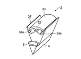
- FIG. 2 is a perspective view showing the configuration of one pole of the rotor 3 in the present embodiment.
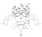
- FIG. 3 is a front view of one pole of the rotor 3 as viewed from the direction of the rotation center axis 4a.
- FIG. 3 in order to facilitate understanding of the configuration of the rotor 3, in addition to the configuration of one pole, the configuration of the pole on both sides in the rotational direction is shown by a broken line.
- the rotor 3 has a core 31 near the rotation center axis 4a, two permanent magnets 34a and 34b provided for each pole, and a rotor outside the permanent magnets 34a and 34b when viewed from the rotation center axis 4a.
- a center bridge 32 of each pole formed between the outer peripheral edge 33 of each pole made of steel material and between the magnet embedded holes 35a and 35b and connecting the core 31 and the outer peripheral edge 33, and provided between the poles It can be roughly divided into q-axis protrusions 37.
- the outer peripheral edge portion 33 for one pole has a substantially arc-shaped cross-sectional shape, and is connected to the core portion 31 via the center bridge 32 at the center in the rotor rotation direction.
- the outer peripheral surface of the outer peripheral edge portion 33 has a curvature radius smaller than the distance from the rotation center axis 4 a to the rotor outermost peripheral portion.
- the radius of curvature of a part of the outer peripheral edge 33 may be smaller than the distance from the rotation center axis 4a to the outermost periphery of the rotor, instead of the entire outer peripheral edge 33 as described above.
- the outer peripheral surface of the outer peripheral edge portion 33 does not have to be a curved surface, and the outer peripheral surface of the outer peripheral edge portion 33 located on the extension passing through the center bridge 32 as viewed from the rotor rotation center The distance from the rotation center should be long.
- the torque of the permanent magnet embedded type rotating electrical machine can be increased by increasing the magnetic resistance of the center bridge 32 and decreasing the magnetic resistance of the stator and the outer peripheral edge portion 33 disposed on the outer periphery of the rotor. it can.
- a magnet embedding hole 35a for holding the permanent magnet 34a and a magnet embedding hole 35b for holding the permanent magnet 34b are provided inside the outer peripheral edge portion 33.
- the magnet embedding holes 35 a and 35 b are surrounded in three directions by the outer peripheral edge portion 33, the center bridge 32 and the core portion 31.
- the outer peripheral edge portion 33 supports the permanent magnets 34 a and 35 b on the side of the central rotation axis 4 a against the centrifugal force acting on the permanent magnets 34 a and 34 b when the rotor 3 rotates.
- Each outer peripheral edge portion 33 corresponding to each pole is aligned in the rotor rotational direction with a gap between adjacent outer peripheral portions.
- the gap between the two outer peripheral portions 33 is located on the opposite side to the center bridge 32, that is, in the middle between the poles.
- the magnet embedding holes 35 a and 35 b are in communication with the outer periphery of the rotor via the gap between the two outer peripheral portions 33.
- Magnet embedding holes 35a and 35b are arranged in an inverted V-shape.
- the region (core 31) on the rotation center axis 4a side of the inner peripheral wall of the magnet embedding holes 35a and 35b is apart from the center between adjacent poles and between the two magnet embedding holes (that is, the center bridge 32) Is inclined in a direction away from the central axis 4a of rotation. For this reason, the center bridge 32 is located at a position radially outwardly of the inscribed circle 36 of all the magnet embedding holes 35 a and 35 b of the rotor 3.
- the q-axis projection 37 passes through the gap between the two outer peripheral edge portions 33 at a central position between the poles of the core portion 31 and protrudes in the centrifugal direction (the direction away from the rotation center axis 4a).
- the magnet embedding holes 35a and 35b are provided with positioning projections 38a and 38b for restricting the movement of the permanent magnets 34a and 34b to the q-axis projection 37 side.
- the positioning projections 38a and 38b are regions of the inner walls of the magnet embedding holes 35a and 35b which are radially outward of the rotor when viewed from the permanent magnets 34a and 34b, that is, the end on the q axis projection 37 side of the outer peripheral edge 33 And protrudes toward the rotation center axis 4a.
- the permanent magnets 34a and 34b are pressed against the positioning projections 38a and 38b and fixed in the magnet embedding holes 35a and 35b. At this time, an adhesive is used to help fix the permanent magnets 34a and 34b to the magnet embedding holes 35a and 35b.
- the center bridge 32 constituting the rotor 3 is austenitized (demagnetized) by nitriding and heating by the method disclosed in Japanese Patent Application Laid-Open No. 2002-69593, and then it is thermally cooled by cooling and annealing. The distortion is removed. Specifically, it is as follows.
- the center bridge 32 is nitrided to generate a nitrided phase having a low saturation magnetic flux density in that portion, thereby reducing the saturation magnetic flux density of a part of the member.
- a rolled ferromagnetic material plate is used as a rotor steel plate to be subjected to the nitriding treatment.
- nitriding treatment such as ion nitriding, ion implantation, gas nitriding and the like is used. It is usually processed at a temperature of 800 ° C. or less. Moreover, it is not necessary to attach nonmagnetic metal etc. beforehand.
- the material is not limited as long as it is a ferromagnetic material that can be nitrided. Therefore, as long as it is an Fe-based material, it may be a mass-produced, relatively inexpensive Fe—Si-based electromagnetic steel plate or the like, or a ferritic stainless steel or the like.
- the portion not to be nitrided is masked with a metal plate or the like.
- the masked rotor steel plate is housed in a chamber, the substrate temperature is heated to 500-800 ° C., and a gas containing nitrogen, for example, a mixed gas of nitrogen and hydrogen, is introduced into the chamber, and then the gas is used to generate plasma for nitriding Form a nitrided phase from the surface of the magnetic steel sheet.
- austenite is formed or Fe 4 N and Fe 2-3 N are formed depending on the cooling rate after nitriding.
- the saturation magnetic flux density is the largest in Fe 4 N, and the saturation magnetic flux density decreases in the order of Fe 2 -3N and ⁇ Fe-N.
- ⁇ Fe-N is a nonmagnetic phase. The saturation flux density of these phases is smaller than the value of ⁇ Fe.
- Si itself is an element that promotes nitriding.
- the thickness of the nitrided layer also increases and the saturation magnetic flux density decreases. Therefore, it is possible to set the saturation magnetic flux density of the steel plate to a desired value by changing the nitriding treatment conditions such as the nitriding treatment time.
- gas species, gas composition ratio, gas pressure, gas flow rate, crystal orientation, crystal grain size, surface state, cooling rate, acceleration voltage and the like affect the formation of the nitrided phase. That is, in order to form the nitrogen compound from the surface to the inside of the base material, raising the treatment temperature, selecting a gas type during nitriding treatment, and selecting the composition of the base material can be mentioned. In the case of plasma nitriding, a sulfuritriding or carbonitriding method can also be applied. By selecting the gas type and flow rate ratio, it is possible to preferentially grow Fe 2-3 N over Fe 4 N.
- nitriding can be performed by ion implantation or gas nitriding.
- ion implantation the above-described compound is formed in the portion implanted with nitrogen ions, and the saturation magnetic flux density is reduced. Also by these, it is possible to reduce saturation magnetic flux density Bs by optimizing conditions.
- the saturation magnetic flux density is lowered by the nitriding treatment because the nitride is formed. Therefore, in the case of a ferromagnetic alloy steel containing Fe such as a carbon steel or a ferritic stainless steel as well as the silicon steel plate, the nitriding treatment It is possible to realize a reduction in the saturation flux density due to In particular, since the thickness of the nitrided phase changes due to the presence of an alloy element or C (carbon) which easily forms a compound with nitrogen, the alloy element concentration of these base materials is taken into consideration in order to obtain the set saturation magnetic flux density. There is a need to.
- the rotor 3 in the present embodiment has a configuration in which the magnet embedded holes 35a and 35b communicate with the outer periphery of the rotor. The reason why this configuration is adopted will be described below.
- the rotor in order to achieve both the purpose of reducing leakage flux and the purpose of securing the strength of the rotor, the rotor is configured by combining a rotor steel plate with side bridges and a rotor steel plate without side bridges. It was For this reason, the rotor of the conventional example has problems such as increased manufacturing cost.
- a configuration in which the magnet embedded holes 35a and 35b communicate with the outer periphery of the rotor that is, a configuration without the side bridge in the conventional example is adopted as the configuration of the rotor.
- the rotor since the rotor does not have the side bridge at the outermost periphery, no assembly residual stress remains at the outermost periphery of the rotor.
- the centrifugal stress generated by the centrifugal force when the rotor rotates is concentrated on the center bridge, but the centrifugal stress acting on this center bridge is a tensile stress, so that the center bridge will not be damaged by adjustment of the width of the center bridge etc. It is easy to deal with.
- the rotor configuration in which the magnet embedding holes 35a and 35b communicate with the outer periphery of the rotor provides the following great advantages.
- the rotor 3 in the present embodiment has the same cross-sectional shape regardless of any plane perpendicular to the rotor rotation axis. For this reason, the rotor 3 in the present embodiment has an advantage in manufacturing. Even when the rotor 3 is formed of laminated steel plates, it is not necessary to prepare a plurality of types of steel plates having different hole shapes, and only one type of steel plate may be prepared. Therefore, it is possible to suppress the cost of the steel plate overwhelmingly low from the aspect of the investment cost of the internal cutting die for forming the steel plate, from the aspect of parts management as well as from the aspect of strength and magnetic field design.
- the rotor 3 in the present embodiment has less leakage paths of magnetic flux as compared with the conventional example having the side bridge. For this reason, the magnet flux is easily linked to the winding, which contributes to an increase in torque.
- the rotor 3 according to the present embodiment is also advantageous in terms of cooling. That is, the rotor 3 is well ventilated in the direction of the rotational axis, and is advantageous for cooling, particularly magnet cooling. Therefore, by adopting the rotor 3 according to the present embodiment, the restriction on the motor capacity can be relaxed.
- the permanent magnets 34a and 34b are supported by the outer peripheral edge portion 33 with uniform stress over the entire length. Therefore, stress is less likely to be generated inside permanent magnets 34 a and 34 b, and permanent magnets 34 a and 34 b can be protected from breakage.
- the q-axis projection 37 can generate strong reluctance torque, and contributes to an increase in torque generated in the rotor.
- the outer peripheral edge portion 33 there is a shape of the outer peripheral edge portion 33.
- the harmonic component of the torque generated in the rotor can be converted to the fundamental wave component, and the torque pulsation can be reduced and the torque can be increased.
- stress concentration a phenomenon that when a force is applied to the uneven portion, a high stress locally occurs due to a phenomenon called stress concentration.
- the magnet embedding holes 35 a and 35 b are in communication with the outer periphery of the rotor, no residual stress remains in the outer peripheral edge portion 33 which is the outermost peripheral region of the rotor 3. Therefore, in the present embodiment, in order to increase the torque, it is easy to provide unevenness on the outer peripheral surface of the outer peripheral edge portion 33 which is the outermost peripheral region of the rotor 3.
- the radius of curvature of the outer peripheral surface of the outer peripheral edge 33 located outside the permanent magnet as viewed from the rotor rotation center is smaller than the distance from the rotor rotation center to the rotor outermost periphery.
- the center bridge 32 where the centrifugal stress is concentrated when the rotor 3 rotates is far from the inside of the inscribed circle 36 where the residual stress due to the interference fit processing mainly occurs, The strength of the center bridge 32 at the time of rotation can be increased.
- positioning protrusions 38a and 38b are provided on the outer peripheral edge portion 33 which is located radially outward as viewed from the permanent magnets 34a and 34b. Therefore, pressing permanent magnets 34a and 34b against positioning projections 38a and 38b prevents imbalance of centrifugal force generated in two permanent magnets 34a and 34b forming one pole, and each permanent magnet is generated. Unbalanced magnetic flux distribution can be prevented.
- the center bridge 32 is demagnetized to significantly reduce the leakage flux of the permanent magnet which is routed through the center bridge. Thereby, the magnetic flux of the magnet linked to the stator winding can be increased, which contributes to the torque increase.
- the structure for supporting the magnetic centrifugal force with one center bridge as in the present embodiment is advantageous in demagnetizing a part of the rotor for the following reasons.
- Ferrite and martensite are body-centered cubic lattices, and their lattice spacing is long.
- austenite is a face-centered cubic lattice, and the lattice distance is short. That is, generally, there is a property that the size shrinks by reforming ferrite-martensite to austenite.
- leakage flux can be cut off by austenitizing a portion (center bridge) not constrained. is there. Because of the demagnetization of the freely stretchable and contractible parts that are not dimension constrained, no stress is generated.
- the present embodiment is superior in strength to those disclosed in JP-A-2002-69593, JP-A-2005-269840, JP-A-2013-143791 and the like. .
- the present embodiment it is possible to realize a permanent magnet embedded type rotary electric machine which is excellent in the strength of the rotor and can be manufactured at low cost. Further, according to the present embodiment, it is possible to increase the torque generated by the rotor without reducing the strength of the rotor.
- the permeability may be lowered by using work hardening or thermal strain.
- the permeability of the center bridge may be lowered by performing slow cooling.
- the occurrence of processing and distortion always involves dimensional changes, so that stress is generated when there is a side bridge.
- such a stress does not occur even if a dimensional change occurs due to work hardening or the like.
- a silicon steel plate is used as a rotor material, but a general steel material may be used, or a ferritic / martensitic ferromagnetic stainless steel or austenitic stainless steel may be hardened by work hardening. You may use what you did.
- an interference fit was mentioned as a method of coupling with the shaft, but a method of transmitting torque with a key on a clearance fit, a method of transmitting torque with a spline or similar structure is also possible Good.
- clearance fit although assembly side stress does not occur, residual stress does not occur, but stress occurs due to dimensional change due to austenitization or thermal strain, and shear stress also occurs due to centrifugal force.
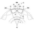
- FIG. 4 is a front view showing the configuration of a rotor 3 'of a synchronous reluctance motor according to another embodiment of the present invention.
- the holes 35a and 35b do not hold the magnets and serve to reduce the horizontal axis inductance.
- a part or all of the outer peripheral surface of the outer peripheral edge portion 33 has a curvature radius larger than the distance from the rotor rotation center axis 4a to the rotor outermost peripheral portion. Is preferred.
- the outer peripheral surface of the outer peripheral edge portion 33 does not have to be a curved surface, and the outer peripheral surface of the outer peripheral edge portion 33 located on the extension passing through the center bridge 32 as viewed from the rotor rotation center
- the distance from the rotation center should be short.
- This shape has the effect of increasing the torque in the reluctance motor.
- the centrifugal stress is small due to the absence of the magnet, but if there is a side bridge, the assembly residual stress is generated there and the shear stress is caused due to the centrifugal force generated in the outer peripheral portion 33. Also occur. In the configuration shown in FIG. 4, such problems do not occur because the holes 35a and 35b communicate with the outer periphery of the rotor.
- the same effect as the above embodiment can be obtained by making the center bridge 32 nonmagnetic or reducing the magnetic permeability.
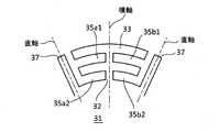
- FIG. 5 shows an example of the configuration of the rotor of such a synchronous reluctance motor.
- each of the horizontal shaft holes 35a1, 35a2, 35b1 and 35b2 communicates with the outer periphery of the rotor on the side opposite to the center bridge 32.
- two pairs of holes are formed in the radial direction of the rotor with the center bridge 32 interposed therebetween to form one pole, three or more pairs of holes may be formed. .
- this configuration is applicable not only to synchronous reluctance rotary electric machines but also to permanent magnet embedded type rotary electric machines. That is, the horizontal axis hole in FIG. 5 may be used as a hole for embedding a permanent magnet, and the rotor of a permanent magnet embedded type rotary electric machine may be configured.
- FIG. 6 shows an example of the configuration of the rotor of such a permanent magnet embedded type rotary electric machine.
- the pair of holes 35a3 and 35b3 and the pair of holes 35a4 and 35b4 are formed with the center bridge 32 interposed therebetween to form one pole, but three or more pairs of holes are formed. You may
- FIG. 7 is a view showing the configuration of the rotor 3b of such a permanent magnet embedded type rotary electric machine.
- two center bridges 32 are formed per pole along the rotor rotation direction.
- Two holes 35 are formed on both sides of each center bridge 32 in the rotational direction of the rotor.
- the core portion 31 of the rotor 3 b is connected to the outer peripheral edge portion 33 on the outer side in the rotor rotational direction of the hole 35 via each center bridge 32.
- Two magnets 34 are embedded in the center two holes 35 among the four holes 35 in one pole along the rotor rotational direction. Further, among the four holes 35 in one pole, one magnet 34 is embedded inside the rotor rotation direction inside two holes 35 outside the rotor rotation direction, and one weight 34a outside the rotor rotation direction. Is embedded.
- two radiation protrusions 39 protrude near the boundary between the magnetic poles, and one radiation protrusion 39a protrudes near the center of the magnetic pole.
- the above is the schematic configuration of one magnetic pole in the rotor 3b. And in the example shown in FIG. 7, four magnetic poles are comprised by the rotor 3b whole.
- the central radiation protrusion 39a is in the form of an umbrella. Therefore, the radiation protrusion 39a at the center in the rotor rotational direction is hereinafter referred to as an umbrella-like radiation protrusion 39a.
- the umbrella-like radial projections 39a have side projections 392 covering part or all of the two outer peripheral edge portions 33 on both sides in the rotor rotational direction from the outer peripheral side of the rotor.
- the two radiation protrusions 39 have mountain-shaped side protrusions 391, the side protrusions 391 are separated from the end of the outer peripheral edge portion 33 in the rotor rotation direction.
- the distance from the outer peripheral edge portion 33 in the rotor rotation direction is different among the plurality of radial projections, and the distance between the umbrella-like radial projection 39a located at the center of the magnetic pole and the outer peripheral edge portion 33 It is shorter than the distance between the band-like radiation projection 39 located at the boundary and the outer peripheral edge portion 33.
- the distance between the outermost periphery of the umbrella-like radiation projection 39a located at the center of the magnetic pole and the rotation center axis 4a is greater than the distance between the outermost periphery of the outer peripheral edge 33 and the rotation center axis 4a. long. That is, the outermost periphery of the umbrella-like radiation projection 39 a is closer to the stator than the outermost periphery of the outer peripheral edge portion 33.
- the outer peripheral surface of the rotor is a smooth connection of the radial projections 39 and 39a having the outer peripheral edge portion 33 and the side projections 391 and 392, respectively, so that the air flow is less likely to occur. Therefore, according to this aspect, the windage loss of the rotor 3b can be reduced.
- the number of magnetic poles of the rotor 3b can be reduced as compared with the above embodiment (see FIGS. 2 and 3). Hereinafter, this effect will be described.
- the umbrella-like radial projection 39a at the center of the magnetic pole covers a wide range of the outer peripheral edge 33 on both sides in the rotor rotational direction, and the distance to the outer peripheral edge 33 is short. For this reason, in this aspect, the magnetic resistance between the umbrella-like radial projection 39a at the center of the magnetic pole and the two outer peripheral portions 33 is small.
- the umbrella-like radial projection 39a at the center of the magnetic pole is closer to the stator than the outer peripheral edge portion 33, and the magnetic resistance with the stator is small. For this reason, the magnetic flux is likely to pass through the center of the magnetic pole where the umbrella-like radiation protrusion 39a is located.
- the umbrella-like radiation protrusion 39a has a narrow width in the vicinity of the center in the radial direction. For this reason, the magnetic short circuit which makes a path
- the weight 35a having no magnetomotive force is disposed on both sides in the rotor rotation direction, and the magnetomotive force in the vicinity of the umbrella-like radiation projection 39a is high. Therefore, within the range of one magnetic pole, a distribution of magnetomotive force close to one sine wave can be obtained.
- the range including two center bridges 32 can be set as one magnetic pole, and the number of magnetic poles of the entire rotor can be halved. Therefore, compared to a rotor including one center bridge 32 per magnetic pole, it is possible to reduce the control speed of the inverter for driving the permanent magnet embedded type rotary electric machine by half.
- the center bridge 32 is demagnetized as in the above embodiment (FIGS. 2 and 3). Therefore, as in the above embodiment, it is possible to widen the width of the center bridge 32 in the rotor rotational direction, and to increase the strength of the center bridge 32 when the rotor 3 rotates.
Landscapes
- Engineering & Computer Science (AREA)
- Power Engineering (AREA)
- Manufacturing & Machinery (AREA)
- Permanent Field Magnets Of Synchronous Machinery (AREA)
- Iron Core Of Rotating Electric Machines (AREA)
Abstract
ロータの強度に優れ、かつ、低コストで製造することができ、ロータが発生するトルクを増加させることが可能な回転電機を提供する。ロータ(3)には、周方向に沿って1極当たり2個の穴(35a)および(35b)が形成されている。2個の穴(35a)および(35b)は、ロータ外周と連通し、各極において2個の穴のロータの半径方向外側の外周縁部(33)がロータの半径方向内側の芯部(31)と当該2個の穴間のセンタブリッジ(32)を介して繋がっている。このセンタブリッジ(32)は、非磁性化または低透磁率化されている。従って、センタブリッジ(32)の幅を広くしても、センタブリッジ(32)を介した漏れ磁束を低減することができる。
Description
この発明は、電動機、発電機等の回転電機に関する。
図8(a)、図8(b)は、従来の永久磁石埋め込み式回転電機の一例であるIPM電動機のロータの構成を示す断面図であり、図8(c)は、その外周面を示す図である。この従来例のIPM電動機は、特許文献1に開示されたものである。このIPM電動機は、ロータ10の外側に向かって広がるようにV字状に配置した2つの永久磁石13a、13bを一極分とするものであり、2つの永久磁石13a、13bをロータ10の内部に複数組埋め込んで、複数の極を形成したものである。また、ロータ10は、図8(a)に示す積層鋼板11と、図8(b)に示す積層鋼板12を、図8(c)に示すように一枚ずつ、または数枚単位で交互に積層して構成したものである。
図8(a)に示すように、積層鋼板11には、一極分として、2つの保持穴部18a、18bと、2つの空洞部14a、14bと、2つの空洞部15a、15bとを形成し、これらを複数組形成している。具体的には、一極分として、V字状に配置され、2つの永久磁石13a、13bを保持する2つの保持穴部18a、18bと、2つの保持穴部18a、18b同士の間の部分(V字の中央部分)に配置され、各保持穴部18a、18bと各々連通する2つの空洞部14a、14bと、隣接する他極との間の部分(V字の端部分)に配置され、各保持穴部18a、18bと各々連通する2つの空洞部15a、15bとを形成している。
保持穴部18a、空洞部14a、空洞部15aは、連続した1つの領域(穴)となっており、また、保持穴部18b、空洞部14b、空洞部15bも、連続した1つの領域(穴)となっており、積層鋼板11の打ち抜き加工時には、各々、1つの穴として打ち抜けばよい。打ち抜き加工により、空洞部15a、15bの外縁側にサイドブリッジ19a、19bが形成されることになる。
また、図8(b)に示すように、積層鋼板12には、一極分として、2つの保持穴部18a’、18b’と、2つの空洞部14a’、14b’と、2つの切欠部16a、16bとを形成し、これらを複数組形成している。積層鋼板12における保持穴部18a’、18b’、空洞部14a’、14b’は、各々、積層鋼板11における保持穴部18a、18b、空洞部14a、14bと同等のものである。具体的には、一極分として、V字状に配置され、2つの永久磁石13a、13bを保持する2つの保持穴部18a’、18b’と、2つの保持穴部18a’、18b’同士の間の部分(V字の中央部分)に配置され、各保持穴部18a’、18b’と各々連通する2つの空洞部14a’、14b’と、各空洞部15a、15bと各々重なるように配置され、各保持穴部18a’、18b’と各々連通すると共に積層鋼板12の外縁まで通じる2つの切欠部16a、16bとを形成している。各切欠部16a、16bは、各空洞部15a、15bを各々内部に含むように配置されており、これにより、各空洞部15a、15bと各々重なるように配置される。
保持穴部18a’、空洞部14a’、切欠部16aは、連続した1つの領域(切り欠き)となっており、また、保持穴部18b’、空洞部14b’、切欠部16bも、連続した1つの領域(切り欠き)となっており、積層鋼板12の打ち抜き加工時には、各々、1つの切り欠きとして打ち抜けばよい。
積層鋼板11における空洞部14aと空洞部14bの間、積層鋼板12における空洞部14a’と空洞部14b’との間には、センタブリッジ19cがある。積層鋼板11および12において、永久磁石よりも内周側の領域と外周側の領域は、このセンタブリッジ19cを介して繋がっている。
そして、上記積層鋼板11、12を一枚ずつ交互に積層した場合には、ロータ3の外周面は、図8(c)に示す外観となり、切欠部16a、16bが各々列になって、積層鋼板1枚おきに配置されることになる。
この従来例においては、積層鋼板11と積層鋼板12とを交互積層しており、積層鋼板12においては、磁束が切欠部16a、16bを通過することになるので、積層鋼板11においては、サイドブリッジ19a、19bの幅を細くしなくても、磁気短絡を低減することができる。具体的には、積層鋼板12に切欠部16a、16bが有るため、各鋼板における永久磁石とロータ外周面との間の鉄心の断面積を総計した総断面積(即ち、サイドブリッジ19a、19bの部分の断面積を総計した総断面積)が1/2となり、その結果、磁気短絡を低減することになる。
また、積層鋼板12においては、隣接する他極との間の部位に切欠部16a、16bが形成され、鉄心が存在しないため、切欠部16a、16bにおける磁気抵抗を、サイドブリッジ19a、19bにおける磁気抵抗よりも大きくすることができる。そして、積層鋼板11と積層鋼板12とを交互積層しているので、積層鋼板11のみを用いた場合よりも磁気抵抗を大きくすることができる。従って、切欠部16a、16bにおける磁気短絡の低減により、磁束漏れを抑制して、多くの磁束をステータ側に供給でき、電動機効率の向上を図ることができる。更に、積層鋼板12において、d軸磁束、q軸磁束の通過部分には鉄心が存在しているので、所望のリラクタンストルクを維持することができる。
上記構成により、打ち抜き加工性や耐遠心力性のために、サイドブリッジ19a、19bを所定の幅とする必要がある場合でも、切欠部16a、16bの存在により、サイドブリッジ19a、19bの幅として、所定の幅を確保しつつ、磁気抵抗を大きくして、磁束漏れを抑制することができる。
ところで、上述した従来の永久磁石埋め込み式回転電機は、形状の異なる複数種類のロータ鋼材によりロータが構成されていたため、次のような問題があった。まず、ロータの製造時に、ロータ鋼材を製造するための複数種類の打ち抜き型が必要になり、部材・型の管理が煩雑になる問題があった。また、形状の異なるロータ鋼材は強度特性が互いに異なる。それにも拘わらず、従来の永久磁石埋め込み式回転電機では、複数種類のロータ鋼材の各間で、磁石・シャフトの形状・配置を同一とする必要がある。このため、磁石・シャフトの形状・配置の設計範囲が大幅に狭められることとなる。この結果、小さな磁石・細いシャフトとせざるを得ず、このため、回転電機の回転数若しくはトルクが大きく制限される。また、形状の異なる複数種類のロータ鋼材を積層させてロータを構成する場合、ロータの設計時に、3次元での磁界計算・強度計算が必要であり、計算負荷が増大し、また、計算精度が低下する問題があった。また、形状の異なる複数種類のロータ鋼材は、一体物の鋼材から例えばワイヤカットなどによる除去加工によって形成することができない。このため、加工コストが増大する問題があった。
また、従来の永久磁石埋め込み式回転電機は、ロータを構成する2種類の鋼板のうちの1種類にサイドブリッジ19aおよび19bがあるため、以下の問題があった。まず、サイドブリッジ19aおよび19bがあることにより、永久磁石の漏れ磁束が依然として少なからず残存しており、また、磁気抵抗もゼロには程遠い。これがロータに発生させるトルクを増加させるのを妨げていた。また、従来の永久磁石埋め込み式回転電機は、ロータにサイドブリッジ19aおよび19bがあるため、ロータ軸方向の風通しが悪い。このロータの風通しの悪さが、ロータ、その中でも特に永久磁石の冷却を妨げる要因となっていた。また、ロータにサイドブリッジ19aおよび19bがあるため、遠心力に対して永久磁石を支える力が不均一になり、永久磁石内部に大きな応力が発生する、という問題があった。
また、一般に永久磁石埋め込み式回転電機は、シャフトに対してロータ鋼材を嵌め合い固定する場合に、ロータ鋼材に周方向の組み立て残留応力が残る。この組み立て残留応力が主に残留する範囲は、ロータ軸を中心とした円周上に穴や切り欠きが存在しない半径範囲(つまりリング状につながっている範囲)である。従来例の場合、サイドブリッジ19aおよび19bがあるので、ロータの最外周にはリング状領域があり、この最外周のリング状領域には引張残留応力が残る。また、サイドブリッジ19aおよび19bには、ロータの回転時に遠心力に起因したせん断応力が加わる。従って、ロータの回転時にサイドブリッジ19aおよび19bが破損するのを防止するために、サイドブリッジ19aおよび19bの幅を広げる必要がある。このため、従来例では、漏れ磁束を削減することが困難であった。
また、従来例では、センタブリッジ19cのある位置の近くに大きな組み立て残留応力が残存する。加えて、ロータの回転時には、遠心力による大きな引っ張り応力(以下、遠心応力)がセンタブリッジ19cに発生する。従来の永久磁石埋め込み式回転電機のロータは、この組み立て残留応力が発生する領域と、遠心応力が発生する領域が近接しており、ロータの強度設計が難しかった。ロータの高速回転を可能にするためには、引張残留応力の発生範囲に大きな応力が発生しないようにする必要がある。この応力緩和のために、例えばセンタブリッジ19cに曲率半径の大きな面取りを行うことも考えられる。しかし、そのような曲率半径の大きな面取りを施すと、磁石を配置するスペースが減り、トルクが制限される。このように、従来例においては、応力を緩和する有効な手段がなかったため、ロータの回転数が制約され、あるいは磁石の大きさが制約されてトルクが制約されるといった問題があった。
また、一般に、ロータの外周面に凹凸を設けると、ロータに発生するトルクの高調波成分を基本波成分に転換することができ、トルク脈動を減らし、トルクを増大させることができる。しかし、従来例のように、磁石埋め込み穴の外側に穴や窪みのないリング状の最外周領域のあるロータの場合、最外周のリング状の領域に組み立て残留応力が残存する。従って、従来のロータにおいて、このような残留応力の残存しているロータの最外周面に応力集中を招く凹凸を設けるのは困難である。このため、従来の永久磁石埋め込み式回転電機は、ロータの外周面に凹凸を設けてトルクを高めることが困難であった。
また、従来例では、センタブリッジが強磁性材料のままのため、永久磁石の漏れ磁束が依然として少なからず残存しておりゼロには程遠い。これがロータに発生させるトルクを増大させるのを妨げていた。
この発明は以上のような事情に鑑みてなされたものであり、その第1の目的は、ロータの強度に優れ、かつ、低コストで製造することができる回転電機を提供することにある。また、この発明の第2の目的は、ロータの強度を低下させることなく、ロータが発生するトルクを増加させることにある。
この発明は、センタブリッジを間に挟んで周方向に隣り合った偶数個の穴が極毎に形成されてなるロータを有し、前記ロータの各極において前記センタブリッジを挟んだ偶数個の穴は前記センタブリッジの反対側において前記ロータの外周と連通しており、前記センタブリッジを非磁性化または前記ロータにおける前記センタブリッジ以外の部分よりも透磁率を低下させたことを特徴とする回転電機を提供する。
この発明によれば、1極分の偶数個の穴をロータ外周に連通させたため、ロータの最外周に組み立て残留応力の残存領域が発生しない。このため、回転時におけるロータの強度を高めることができる。また、1極分の偶数個の穴をロータ外周に連通させる構成であり、そもそもサイドブリッジが不要であるため、漏れ磁束低減のためにサイドブリッジのない鋼板とサイドブリッジのある鋼板とを組み合わせてロータを構成する必要もない。従って、1種類の鋼板のみを積層させてロータを製造できる。さらに、センタブリッジが非磁性化、或いは低透磁率化されているため、漏れ磁束は極めて少ない。これにより、同じ磁石量でも、出力トルクに寄与する磁束を増やすことができる。
以下、図面を参照しつつこの発明の実施形態について説明する。
図1は、この発明の一実施形態である永久磁石埋め込み式回転電機の全体構成を示す縦断面図である。図1において、フレーム1は、永久磁石埋め込み式回転電機全体を覆う筐体であり、鉄、アルミ、ステンレスなどにより構成されている。フレーム1の内側には、中空円筒状の固定側鉄心2が設けられている。この固定側鉄心2は、珪素鋼板を積層してなるものである。この固定側鉄心2には、穴が設けられており、この穴には銅線などによるステータ巻線が挿通されている(図示略)。固定側鉄心2の内側には、固定側鉄心2との間に所定のギャップを挟んだ状態で、回転側鉄心であるロータ3が挿通されている。このロータ3は、珪素鋼板を積層してなるものである。ロータ3は、その中心を鉄などによるシャフト4が貫通している。理想的には、シャフト4の中心軸がロータ3の回転中心軸4aとなる。そして、シャフト4は、ベアリング鋼などからなる転がり軸受け5を介して、フレーム1の前後両端に設けられたシールド6に支持されている。
図1は、この発明の一実施形態である永久磁石埋め込み式回転電機の全体構成を示す縦断面図である。図1において、フレーム1は、永久磁石埋め込み式回転電機全体を覆う筐体であり、鉄、アルミ、ステンレスなどにより構成されている。フレーム1の内側には、中空円筒状の固定側鉄心2が設けられている。この固定側鉄心2は、珪素鋼板を積層してなるものである。この固定側鉄心2には、穴が設けられており、この穴には銅線などによるステータ巻線が挿通されている(図示略)。固定側鉄心2の内側には、固定側鉄心2との間に所定のギャップを挟んだ状態で、回転側鉄心であるロータ3が挿通されている。このロータ3は、珪素鋼板を積層してなるものである。ロータ3は、その中心を鉄などによるシャフト4が貫通している。理想的には、シャフト4の中心軸がロータ3の回転中心軸4aとなる。そして、シャフト4は、ベアリング鋼などからなる転がり軸受け5を介して、フレーム1の前後両端に設けられたシールド6に支持されている。
この例において、永久磁石埋め込み式回転電機は電動機である。この電動機においてロータ3は、ステータ巻線(図示せず)によって作られる回転磁界によってエネルギを与えられ、回転中心軸4a廻りに回転する。
本実施形態の特徴は、ロータ3の構成にある。図2は本実施形態におけるロータ3の1極分の構成を示す斜視図である。また、図3は回転中心軸4a方向からロータ3の1極分を見た正面図である。なお、図3では、ロータ3の構成の理解を容易にするため、1極分の構成に加えて、その回転方向両隣の極の構成を破線により示した。
本実施形態によるロータ3は、回転中心軸4a寄りの芯部31と、極毎に設けられた2個の永久磁石34aおよび34bと、回転中心軸4aからみて永久磁石34aおよび34bの外側のロータ鋼材からなる各極の外周縁部33と、磁石埋め込み穴35aおよび35bの間に形成され、芯部31と外周縁部33とを各々繋ぐ各極のセンタブリッジ32と、極間に設けられたq軸突起37とに大別することができる。
1極分の外周縁部33は、略円弧状の断面形状を有しており、ロータ回転方向中央において、センタブリッジ32を介して芯部31と繋がっている。この外周縁部33の外周面は、回転中心軸4aからロータ最外周部までの距離よりも小さい曲率半径を有している。なお、このように外周縁部33の全部ではなく、外周縁部33の一部の曲率半径を回転中心軸4aからロータ最外周部までの距離より小さくしてもよい。また、外周縁部33の外周面は曲面である必要はなく、ロータ回転中心からみてセンタブリッジ32を通る延長線上に位置する外周縁部33の外周面がその他の位置の外周面に対し、ロータ回転中心からの距離が長ければよい。このようにして、センタブリッジ32は磁気抵抗を高くし、ロータの外周に配置されたステータと外周縁部33との磁気抵抗を低くすることで永久磁石埋め込み式回転電機のトルクを増大することができる。
外周縁部33の内側には、永久磁石34aを保持するための磁石埋め込み穴35aと、永久磁石34bを保持するための磁石埋め込み穴35bが設けられている。この磁石埋め込み穴35aおよび35bは、外周縁部33、センタブリッジ32および芯部31により3方向から囲まれている。外周縁部33は、ロータ3の回転時に永久磁石34aおよび34bに働く遠心力に対抗して永久磁石34aおよび35bを回転中心軸4a側に支持する。各極に対応した各外周縁部33は、隣のものとの間に隙間を挟んでロータ回転方向に並んでいる。2個の外周縁部33間の隙間は、センタブリッジ32と反対側、すなわち、極間の中央に位置している。磁石埋め込み穴35aおよび35bは、この2個の外周縁部33間の隙間を介してロータ外周に連通している。
磁石埋め込み穴35aおよび35bは、逆V字状に配列されている。そして、磁石埋め込み穴35aおよび35bの内周壁における回転中心軸4a側の領域(芯部31)は、隣接する極間の中心から離れて2個の磁石埋め込み穴の間(すなわち、センタブリッジ32)に近づくに従って回転中心軸4aから離れる方向に傾いている。このため、センタブリッジ32は、ロータ3の全ての磁石埋め込み穴35a、35bの内接円36からロータ半径方向外側に離れた位置にある。
q軸突起37は、芯部31の極間の中央の位置において2個の外周縁部33間の隙間を通過して遠心方向(回転中心軸4aから離れる方向)に突き出している。磁石埋め込み穴35aおよび35bには、このq軸突起37側への永久磁石34aおよび34bの移動を規制する位置決め突起38aおよび38bが設けられている。この位置決め突起38aおよび38bは、磁石埋め込み穴35aおよび35bの内壁のうち永久磁石34aおよび34bからみてロータ半径方向外側にある領域、すなわち、外周縁部33の内側のq軸突起37側の端部において、回転中心軸4aに向けて突出している。永久磁石34aおよび34bは、この位置決め突起38aおよび38bに押し当てられ、磁石埋め込み穴35aおよび35b内に固定される。その際、永久磁石34aおよび34bの磁石埋め込み穴35aおよび35bへの固定を補助するために接着剤が使用される。
また、ロータ3を構成するセンタブリッジ32は、特開2002-69593号公報に開示された方法で、窒化および加熱されることでオーステナイト化(非磁性化)されており、その後冷却および焼き鈍しにより熱歪が除去されている。具体的には次の通りである。
本実施形態では、ロータ3の積層鋼板の製造時、センタブリッジ32について窒化処理し、その部分に飽和磁束密度の低い窒化相を生成することで、部材の一部の飽和磁束密度を低下させる。窒化処理の対象となるロータ鋼板としては、例えば、圧延した強磁性材料板が用いられる。窒化処理は、イオン窒化、イオン注入、ガス窒化等の窒化処理が用いられる。通常、800℃以下の温度で処理する。また、非磁性金属等をあらかじめ付着させる必要はない。さらに窒化可能な強磁性材料であればよく、その材質は限定されない。従って、Fe系材料であれば、量産されていて、比較的コストの安いFe-Si系の電磁鋼板等、または、フェライト系ステンレス鋼等であっても良い。
ロータ鋼板において飽和磁束密度を小さくしたいセンタブリッジ32のみ窒化させるため、窒化させない部分については、金属板等でマスキングする。マスキングしたロータ鋼板をチャンバに収容し、基板温度を500-800℃に加熱し、チャンバ内に窒素を含むガス、例えば、窒素と水素の混合ガスを導入後、ガスによりプラズマを生成して窒化処理し、電磁鋼板の表面から窒化相を形成する。
窒素はオーステナイト形成元素であるので、窒化後の冷却速度に依存してオーステナイト(γFe-N)が形成されるか、あるいは、Fe4N、Fe2-3Nが形成される。これらの相の中で飽和磁束密度はFe4Nがもっとも大きく、Fe2-3N、γFe-Nの順に飽和磁束密度は小さくなる。特に、γFe-Nは非磁性相となっている。これらの相の飽和磁束密度はαFeの値よりも小さい。
窒化を加速させるために、母合金中に他の添加元素を含ませるか、または、窒化処理中に別の元素を添加しても良い。ケイ素鋼の場合、Si自体が窒化を促進させる元素である。
窒化処理を高温で長時間進めれば、窒化層の厚さも厚くなり、飽和磁束密度は減少する。そのため、窒化処理時間等の窒化処理条件を変えることにより、鋼板の飽和磁束密度を目的の値にすることが可能となる。
このような温度、時間以外に、ガス種、ガス組成比、ガス圧力、ガス流量、結晶方位、結晶粒径、表面状態、冷却速度、加速電圧等が、窒化相の形成に影響する。すなわち、窒素化合物を表面から母材内部まで形成するためには、処理温度を高くすること、窒化処理中のガス種を選択すること、母材の組成を選択することが挙げられる。プラズマ窒化の場合には、浸硫窒化あるいは浸炭窒化方法も適用することができる。ガス種および流量比を選択することにより、Fe4NよりもFe2-3Nを優先的に成長させることが可能である。
また、プラズマ窒化以外にも、イオン注入法あるいはガス窒化法によって窒化が可能である。例えば、イオン注入法を用いる場合に、窒素イオンを注入した部分で上記化合物が形成され、飽和磁束密度が減少する。これらによっても、条件を適正化することにより飽和磁束密度Bsを低下させることが可能である。
窒化処理で飽和磁束密度が低下するのは窒化物が形成されるためであるから、ケイ素鋼板のみでなく、炭素鋼、フェライト系ステンレス鋼等のFeを含む強磁性合金鋼であれば、窒化処理による飽和磁束密度の低下を実現することが可能である。特に、窒素との化合物を形成しやすい合金元素やC(炭素)の存在によって窒化相の厚さが変化するので、設定した飽和磁束密度を得るためにはこれらの母材の合金元素濃度を考慮する必要がある。
窒化処理後は、歪みを除去するため、または、歪みを拡散させるために、追加熱処理を行う。
以上がセンタブリッジ32を非磁性化する方法の詳細である。
以上がセンタブリッジ32を非磁性化する方法の詳細である。
本実施形態におけるロータ3は、磁石埋め込み穴35aおよび35bがロータ外周に連通した構成となっている。以下、この構成を採用した理由を説明する。
電動機の製造では、焼き嵌めなどの締り嵌めによって、シャフトとロータ鋼材を組み立てる方法が一般的である。この締り嵌めの工程において、ロータ鋼材には周方向に引張応力が残留する。このロータの組み立て時に発生する残留応力は、ロータの高速回転中にも残ったままである。本願発明者らが有限要素法により計算したところ、この残留応力は、ロータ鋼材に穴や窪みなどのある部分と同じ半径を持つ円周上には殆ど発生しないことが確認された(すなわち、穴も窪みもなく、リング状につながっている部分でないと応力は残存しない)。
一方、ロータの回転時、特に高速回転時には、ロータの各部分に強大な遠心力が発生する。その際、従来例のように、ロータがセンタブリッジとサイドブリッジを持つ場合には、このセンタブリッジとサイドブリッジに大きな遠心応力が発生する。この場合、ロータの回転により発生する遠心力により、センタブリッジに引っ張り応力が働くのに対し、サイドブリッジにはせん断応力が発生する。このため、高速回転によるロータの破損を防止するためには、センタブリッジよりはむしろサイドブリッジの強度を十分に高くする必要があり、この点がロータの強度設計を難しくしていた。
また、従来例では、漏れ磁束の低減という目的とロータの強度を確保するという目的の両方を達成するために、サイドブリッジのあるロータ鋼板とサイドブリッジのないロータ鋼板とを組み合わせてロータを構成していた。このため、従来例のロータには、製造コストが嵩む等の問題があった。
そこで、本実施形態では、ロータの構成として、磁石埋め込み穴35aおよび35bがロータ外周に連通した構成、すなわち、従来例におけるサイドブリッジのない構成を採用した。本実施形態によれば、ロータが最外周にサイドブリッジを有していないため、ロータの最外周には組み立て残留応力が残存しない。ロータの回転時の遠心力により発生する遠心応力はセンタブリッジに集中するが、このセンタブリッジに働く遠心応力は引っ張り応力であるため、センタブリッジの幅の調整等によりセンタブリッジが破損に至らないように対処することが容易である。しかも、磁石埋め込み穴35aおよび35bがロータ外周に連通したロータ構成は、以下に述べる大きな利点をもたらす。
まず、従来例と異なり、本実施形態におけるロータ3は、ロータ回転軸に垂直な如何なる平面で切断しても同じ断面形状となる。このため、本実施形態におけるロータ3には、製作面での利点がある。ロータ3を積層鋼板で形成する場合も、穴形状の異なる複数種類の鋼板を用意する必要がなく、1種類の鋼板のみを用意すればよい。従って、鋼板を形成するための内抜き型の投資費用の面からも、部品管理の面からも、強度・磁界設計の面からも鋼板のコストを圧倒的に低く抑えることができる。
また、本実施形態におけるロータ3は、サイドブリッジのある従来例に比して磁束の漏れ経路が少ない。このため、磁石磁束が巻線に鎖交しやすく、これがトルクの増加に貢献する。
さらに本実施形態によるロータ3には冷却面でも利点がある。すなわち、ロータ3は、回転軸方向の風通しがよく、冷却、とりわけ磁石冷却に有利である。従って、本実施形態によるロータ3を採用することにより、電動機容量に関する規制を緩和することができる。
さらに全ての磁石埋め込み穴35aおよび35bをロータ外周に連通させた場合には、永久磁石34aおよび34bは、外周縁部33により全長に亙って均一な応力で支えられることになる。このため、永久磁石34aおよび34bの内部に応力が発生しにくく、永久磁石34aおよび34bを破損から保護することができる。
本実施形態の他の特徴としてq軸突起37がある。このq軸突起37は、強いリラクタンストルクを生むことができ、ロータに発生するトルクの増加に貢献する。
さらに本実施形態の他の特徴として、外周縁部33の形状がある。ロータの外周面に凹凸を設けると、ロータに発生するトルクの高調波成分を基本波成分に転換することができ、トルク脈動を減らし、トルクを増大させることができる。一方、凹凸部に力が加わると、応力集中と呼ばれる現象により、局所的に高い応力が発生することが広く知られている。
従来例のように磁石埋め込み穴がロータ外周に連通しておらず、最外周がリング状に連続したロータの場合、ロータ外周面付近のリング状の領域に組み立て残留応力が残存する。このため従来例のロータにおいて、このような残留応力の残存しているロータの最外周面に応力集中を招く凹凸を設けるのは困難である。
しかしながら、本実施形態において、磁石埋め込み穴35aおよび35bをロータ外周と連通させているため、ロータ3の最外周領域である外周縁部33に残留応力は残存しない。従って、本実施形態では、トルクを増大させるために、ロータ3の最外周領域である外周縁部33の外周面に凹凸を設けることが容易である。
そこで、本実施形態において、ロータ回転中心からみて永久磁石の外側にある外周縁部33の外周面の曲率半径を、ロータ回転中心からロータ最外周部までの距離よりも小さくしている。このように本実施形態では、発生応力を高めることなく、ロータ3に発生するトルクの脈動を減らし、トルクを増大させることができる。
また、本実施形態の特徴として、逆V字状に配列された磁石埋め込み穴35aおよび35bがある。この特徴により得られる効果を説明すると、次の通りである。
まず、シャフト4のロータ3への締り嵌め工程において、ロータ鋼材には周方向に引張応力が残留する。この残留応力は、磁石埋め込み穴35aおよび35bと同じ半径を持つ円周上には殆ど発生しない。従って、本実施形態におけるロータ3では、磁石埋め込み穴35aおよび35bの内接円36よりもロータ半径方向外側には、組み立て残留応力は殆ど残存しない。
一方、ロータ3の回転時には、遠心力による引っ張り応力(遠心応力)がセンタブリッジ32に発生する。磁石埋め込み穴35aおよび35bを逆V字状に配列した場合、このセンタブリッジ32の位置は、残留応力が主に発生する内接円36内よりもロータ半径方向外側に遠ざかる。
このように本実施形態によれば、ロータ3の回転時に遠心応力が集中するセンタブリッジ32は、締り嵌め加工による残留応力が主に発生する内接円36内から遠ざかっているため、ロータ3の回転時におけるセンタブリッジ32の強度を高めることができる。
また、本実施形態では、永久磁石34aおよび34bからみて半径方向外側にある外周縁部33に位置決め突起38aおよび38bが設けられている。従って、永久磁石34aおよび34bを位置決め突起38aおよび38bに押し当てて固定することで、1極をなす2つの永久磁石34aおよび34bに発生する遠心力のアンバランスを防ぐとともに、各永久磁石が発生する磁束分布のアンバランスを防ぐことができる。
なお、従来例のように、永久磁石から見て半径方向内側のロータ鋼材に位置決め突起を設ける方法もあるが、磁石埋め込み穴35aおよび35bを逆V字状に配置してこれを行うには問題がある。組み立て残留応力が発生する範囲近くに、位置決め突起を設けることになるからである。位置決め突起を設ければ同時に凹みもできる。凹みは元来応力集中が発生し易い。この場合、面取り半径を大きくして凹部の面取りをすることができれば、応力集中をある程度は緩和することができるが、十分に応力を緩和できる面取り半径は、磁石の厚みと同等、若しくはそれ以上となることが多く、位置決めの用を成さない。よって従来例のように永久磁石から見て半径方向内側のロータ鋼材に位置決め突起を設けることは、組み立て残留応力に対する位置決め突起の強度を弱めることとなるので好ましくない。
加えて本実施形態においては、センタブリッジ32が非磁性化されていることで、センタブリッジを経路とした永久磁石の漏れ磁束を大幅に削減している。これによりステータ巻線に鎖交する磁石磁束が増加させることができ、トルクアップに寄与している。
本実施形態のようにセンタブリッジ1本で磁石遠心力を支える構造は、以下の理由により、ロータの一部を非磁性化する上で有利である。
フェライトやマルテンサイトは体心立方格子であり、格子間距離が長い。一方、オーステナイトは面心立方格子であり、格子間距離が短い。つまり、一般的に、フェライト・マルテンサイトからオーステナイトに改質することで寸法が縮む性質がある。
本実施形態と同様にブリッジのオーステナイト化による非磁性化によりを行ってトルクアップを図った例として、特開2002-69593号公報、特開2005-269840号公報、特開2013-143791号公報などがあるが、これらは非磁性化処理と同時に大きな応力を発生する。何故なら、これらは回転軸を中心としてリング状に繋がっている部分をオーステナイト化しているからである。
このような形状ではブリッジ部の寸法が拘束されているため、伸縮が起きると大きな応力を生じる。例えば一般的な電磁鋼板の場合、ヤング率は200[GPa]程度であり、例え0.1[%]程度の小さな伸縮が発生したとしても、単純計算で200[MPa]もの応力が発生する。しかし、一般的な電磁鋼板の降伏応力は400[MPa]程度のため、組み立て残留応力や、遠心応力を、残りの200[MPa]の範囲内に収まるよう設計する必要がある。このような理由により特開2002-69593号公報、特開2005-269840号公報、特開2013-143791号公報などは、非磁性化した時点でブリッジに大きな応力を生じ、その結果許容できる遠心応力が小さくなる。これが回転数の制限や磁石量の制限となり、電動機性能を制限する。
なお、これらはサイドブリッジがある場合のセンタブリッジに関しても同様である(サイドブリッジによりセンタブリッジの寸法が拘束される)。
これに対し、本実施形態による構造のように、センタブリッジ1本で磁石の遠心力を支える構造の場合は、寸法拘束されない部位(センタブリッジ)をオーステナイト化すれば漏れ磁束を絶つことが可能である。寸法拘束されていない自由に伸び縮みできる部位の非磁性化のため、応力が発生することはない。
以上のように本実施形態は、特開2002-69593号公報、特開2005-269840号公報、特開2013-143791号公報などに開示されたものと比較しても、強度的に優位である。
以上のように、本実施形態によれば、ロータの強度に優れ、かつ、低コストで製造することができる永久磁石埋め込み式回転電機を実現することができる。また、本実施形態によれば、ロータの強度を低下させることなく、ロータが発生するトルクを増加させることができる。
以上、この発明の一実施形態について説明したが、この発明には他にも実施形態が考えられる。
(1)例えば上記実施形態では、オーステナイト化の例として予め窒化処理するものを挙げたが窒化処理がなくてもよい。
(2)また、上記実施形態ではオーステナイト安定化元素であるNiやCrの付与を行わない例を挙げたが、NiやCrを付与してもよい。
(3)また、上記実施形態では、非磁性化の例として改質を挙げたが、加工硬化や熱歪を用いて透磁率を低下させても良い。例えば、ロータの製造時、レーザあるいは電子ビームを使ってロータ鋼板におけるセンタブリッジの局部加熱を行った後、徐冷を行うことにより、センタブリッジの透磁率を低下させてもよい。加工や歪みが起きるということは、必ず寸法変化を伴うため、サイドブリッジがある場合には応力が発生する。しかしながら、センタブリッジの場合は加工硬化等によって寸法変化が発生したとしてもそのような応力は発生しない。
(4)また、上記実施形態では、ロータ材として珪素鋼板を用いたが一般鋼材を用いても良いし、フェライト系・マルテンサイト系の強磁性ステンレスや、オーステナイト系ステンレスを加工硬化により強磁性化させたものを用いても良い。
(5)また、上記実施形態では、シャフトとの結合方法として締り嵌めを挙げたが、隙間嵌めの上、トルク伝達をキーで行う方法や、スプラインやそれに類似した構造でトルク伝達を行う方法でもよい。隙間嵌めの場合、サイドブリッジがあっても組み立て残留応力は発生しないが、オーステナイト化や熱歪による寸法変化を原因とした応力は発生し、遠心力によるせん断応力も発生する。
(6)また、上記実施形態ではこの発明を電動機に適用したが、この発明は発電機にも勿論適用可能である。
(7)また、上記実施例では永久磁石埋め込み式電動機を例として挙げたが、同期リラクタンス電動機等の磁石レス電動機にも適用可能である。図4はこの発明の他の実施形態である同期リラクタンス電動機のロータ3’の構成を示す正面図である。このロータ3’において、穴35aおよび35bは、磁石を保持せず、横軸インダクタンスを小さくする役割を果たす。トルクアップを図るためには、図4において、外周縁部33の外周面の一部または全部が、ロータ回転中心軸4aからロータ最外周部までの距離よりも大きい曲率半径を有していることが好ましい。また、外周縁部33の外周面は曲面である必要はなく、ロータ回転中心からみてセンタブリッジ32を通る延長線上に位置する外周縁部33の外周面がその他の位置の外周面に対し、ロータ回転中心からの距離が短ければよい。この形状は、リラクタンスモータにおいてトルクを増大させる効果がある。このような同期リラクタンス電動機の場合、磁石がない分だけ遠心応力は小さいが、サイドブリッジがあればそこには組み立て残留応力が発生し、外周縁部33に発生する遠心力を原因として、せん断応力も発生する。図4に示す構成では、穴35aおよび35bがロータ外周に連通しているため、そのような問題は生じない。また、センタブリッジ32を非磁性化または低透磁率化することにより上記実施形態と同様な効果が得られる。
(8)上記実施形態では、1つの極を形成するためにセンタブリッジを間に挟んだ2個の穴をロータに形成した。しかし、1つのセンタブリッジに対して設ける穴は、2個に限定されるものではなく、偶数個であればよい。例えば1つの極を形成するために、ロータ回転方向にセンタブリッジ32を間に挟んだ穴の対をロータ半径方向に沿って複数対形成してもよい。図5は、そのような同期リラクタンス電動機のロータの構成例を示すものである。この例では、センタブリッジ32のロータ回転方向左側にロータ半径方向に並んだ2個の横軸穴35a1および35a2があり、センタブリッジ32のロータ回転方向右側にロータ半径方向に並んだ2個の横軸穴35b1および35b2がある。各横軸穴35a1、35a2、35b1、35b2は、センタブリッジ32と反対側においてロータ外周と連通している。なお、この例では、1つの極を形成するためにセンタブリッジ32を間に挟んだ穴の対をロータ半径方向に2対形成したが、穴の対を3対またはそれ以上形成してもよい。また、この構成は、同期リラクタンス回転電機のみならず、永久磁石埋め込み式回転電機にも適用可能である。すなわち、図5における横軸穴を永久磁石を埋め込むための穴として使用し、永久磁石埋め込み式回転電機のロータを構成してもよい。
(9)上記実施形態では、1つの極を形成するためにセンタブリッジのロータ回転方向両側に各1個の穴をロータに形成したが、1つの極を形成するために、ロータ回転方向両側に2個以上の穴を形成してもよい。図6は、そのような永久磁石埋め込み式回転電機のロータの構成例を示すものである。この例では、センタブリッジ32のロータ回転方向左側にロータ回転方向に並んだ2個の永久磁石埋め込み穴35a3および35a4があり、センタブリッジ32のロータ回転方向右側にロータ回転方向に並んだ2個の永久磁石埋め込み穴35b3および35b4がある。なお、この例では、1つの極を形成するためにセンタブリッジ32を間に挟んだ穴35a3および35b3の対と穴35a4および35b4の対を形成したが、穴の対を3対またはそれ以上形成してもよい。
(10)上記実施形態では、ロータ回転方向に1極当たり1個のセンタブリッジを設けたが、ロータ回転方向に1極当たり複数個のセンタブリッジを設けてもよい。図7はそのような永久磁石埋め込み式回転電機のロータ3bの構成を示す図である。
このロータ3bでは、ロータ回転方向に沿って1極当たり2個のセンタブリッジ32が形成されている。各センタブリッジ32のロータ回転方向両側には2個の穴35が形成されている。ロータ3bの芯部31は、各センタブリッジ32を介して穴35のロータ回転方向外側の外周縁部33と各々接続されている。1極内の4個の穴35のうち中央の2個の穴35には磁石34がロータ回転方向に沿って2個ずつ埋め込まれている。また、1極内の4個の穴35のうちロータ回転方向外側の2個の穴35はそれぞれ、ロータ回転方向内側に1個の磁石34が埋め込まれ、ロータ回転方向外側に1個のオモリ34aが埋め込まれている。また、ロータ3bにおいて、磁極間の境界付近には、2個の放射突起39が突出しており、磁極中央付近に1個の放射突起39aが突出している。以上がロータ3bにおける1磁極分の概略構成である。そして、図7に示す例では、ロータ3b全体で4磁極が構成されている。
1磁極内の3個の放射突起のうちロータ回転方向両側の2個の放射突起39は、回転中心軸4aから離れる方向に突き出している。この放射突起39のロータ回転方向両側の側面には、放射突起39の両側の外周縁部33の外周面の角部に頂上部を向けた山形状の側面突起391が形成されている。また、1磁極内の3個の放射突起のうち中央の放射突起39aは傘状になっている。そこで、以下、このロータ回転方向中央の放射突起39aを傘状放射突起39aという。この傘状放射突起39aは、ロータ回転方向両側の2個の外周縁部33の一部または全部をロータ外周側から覆う側面突起392を有している。これに対し、2個の放射突起39は、山形状の側面突起391を有しているものの、この側面突起391は、外周縁部33の端部からロータ回転方向に離れている。すなわち、この態様では、ロータ回転方向の外周縁部33との距離が複数の放射突起間で異なっており、磁極中央に位置する傘状放射突起39aと外周縁部33との距離は、磁極間境界に位置する帯状の放射突起39と外周縁部33との距離よりも短い。
また、この態様において、磁極中央に位置する傘状放射突起39aの側面突起392よりもロータ半径方向内側の部分の幅(ロータ回転方向の寸法)は、そのロータ回転方向両側の帯状の放射突起39の幅よりも狭くなっている。
また、この態様において、磁極中央に位置する傘状放射突起39aの最外周と回転中心軸4aとの間の距離は、外周縁部33の最外周と回転中心軸4aとの間の距離よりも長い。すなわち、傘状放射突起39aの最外周は、外周縁部33の最外周よりもステータに接近している。
この態様において、ロータ外周面は、外周縁部33と側面突起391および392を各々有する放射突起39および39aが概略滑らかに繋がったものとなり、気流の剥離が起こり難い。従って、この態様によれば、ロータ3bの風損を低減することができる。
また、この態様では、上記実施形態(図2および図3参照)に比べて、ロータ3bの磁極数を低減することができる。以下、この効果について説明する。
a.まず、この態様では、磁極中央の傘状放射突起39aが、そのロータ回転方向両側の外周縁部33の広い範囲を覆い、かつ、外周縁部33との距離が近い。このため、この態様では、磁極中央の傘状放射突起39aと2個の外周縁部33との間の磁気抵抗が小さい。
b.また、磁極中央の傘状放射突起39aは、外周縁部33よりもステータに近く、ステータとの間の磁気抵抗が小さい。このため、磁束は、傘状放射突起39aのある磁極中央を通り易い。
c.また、傘状放射突起39aは、半径方向中央付近の部分の幅が狭い。このため、傘状放射突起39aを経路とした磁気短絡が起きにくい。
d.また、この態様では、ロータ回転方向両側に起磁力を持たないオモリ35aが配置されており、傘状放射突起39a付近の起磁力が高くなっている。このため、1磁極の範囲内において、1正弦波に近い起磁力の分布が得られる。
以上のa~dの効果により、この態様では、図7に示すように、センタブリッジ32を2個含む範囲を1磁極とし、ロータ全体の磁極数を半減させることができる。このため、1磁極当たり1個のセンタブリッジ32を含むロータに比べて、永久磁石埋め込み式回転電機を駆動するインバータの制御速度を半分に低下させることができる。
そして、この態様では、上記実施形態(図2および図3)と同様、センタブリッジ32が非磁性化されている。従って、上記実施形態と同様、センタブリッジ32のロータ回転方向の幅を広げて、ロータ3の回転時におけるセンタブリッジ32の強度を高めることが可能になる。
1……フレーム、2……鉄心、3,3’,3b……ロータ、31……芯部、32……センタブリッジ、33……外周縁部、34a,34b……永久磁石、35a,35b,35a1~35a4,35b1~35b4……穴、36……内接円、37……q軸突起、38a、38b……位置決め突起、39,39a……放射突起、391,392……側面突起、4……シャフト、4a……回転中心軸、5……転がり軸受け、6……シールド。
Claims (14)
- センタブリッジを間に挟んで周方向に隣り合った偶数個の穴が極毎に形成されてなるロータを有し、
前記ロータの各極において前記センタブリッジを挟んだ偶数個の穴は前記センタブリッジの反対側において前記ロータの外周と連通しており、
前記センタブリッジを非磁性化または前記ロータにおける前記センタブリッジ以外の部分よりも透磁率を低下させたことを特徴とする回転電機。 - 前記センタブリッジは、熱処理または加工硬化を利用することにより、変態または歪み発生が行われて非磁性化または低透磁率化されたものであることを特徴とする請求項1に記載の永久磁石埋め込み式回転電機。
- 前記センタブリッジが前記偶数個の穴の内接円よりも前記ロータの半径方向外側に位置していることを特徴とする請求項1に記載の回転電機。
- 前記センタブリッジが前記偶数個の穴の内接円よりも前記ロータの半径方向外側に位置していることを特徴とする請求項2に記載の回転電機。
- 前記ロータは、隣接する極間にロータ回転中心軸から離れる方向に突出したq軸突起を有することを特徴とする請求項1に記載の回転電機。
- 前記ロータは、隣接する極間にロータ回転中心軸から離れる方向に突出したq軸突起を有することを特徴とする請求項2に記載の回転電機。
- 前記ロータは、隣接する極間にロータ回転中心軸から離れる方向に突出したq軸突起を有することを特徴とする請求項3に記載の回転電機。
- 前記ロータは、隣接する極間にロータ回転中心軸から離れる方向に突出したq軸突起を有することを特徴とする請求項4に記載の回転電機。
- 前記穴が永久磁石を保持し、前記回転電機が永久磁石埋め込み型回転電機であることを特徴とする請求項1~8のいずれか1の請求項に記載の回転電機。
- 前記外周縁部の外周面の一部または全部が、ロータ回転中心軸からロータ最外周部までの距離よりも小さい曲率半径を有していることを特徴とする請求項9に記載の回転電機。
- 前記穴の内壁のうち前記ロータ半径方向外側の領域に、前記永久磁石の移動を規制する位置決め突起を有することを特徴とする請求項9に記載の回転電機。
- 前記永久磁石の固定を接着剤により補助したことを特徴とする請求項9に記載の回転電機。
- 前記回転電機が同期リラクタンス回転電機であることを特徴とする請求項1~8のいずれか1の請求項に記載の回転電機。
- 前記外周縁部の外周面の一部または全部が、ロータ回転中心軸からロータ最外周部までの距離よりも大きい曲率半径を有していることを特徴とする請求項13に記載の回転電機。
Priority Applications (4)
| Application Number | Priority Date | Filing Date | Title |
|---|---|---|---|
| PCT/JP2014/071252 WO2016024324A1 (ja) | 2014-08-11 | 2014-08-11 | 回転電機 |
| JP2016542458A JP6210161B2 (ja) | 2014-08-11 | 2014-08-11 | 回転電機 |
| CN201480075629.0A CN106030989B (zh) | 2014-08-11 | 2014-08-11 | 旋转电机 |
| US15/231,821 US10790713B2 (en) | 2014-08-11 | 2016-08-09 | Rotating electrical machine with rotor with plurality of umbrella-shaped portions with demagnetized center bridge portions |
Applications Claiming Priority (1)
| Application Number | Priority Date | Filing Date | Title |
|---|---|---|---|
| PCT/JP2014/071252 WO2016024324A1 (ja) | 2014-08-11 | 2014-08-11 | 回転電機 |
Related Child Applications (1)
| Application Number | Title | Priority Date | Filing Date |
|---|---|---|---|
| US15/231,821 Continuation US10790713B2 (en) | 2014-08-11 | 2016-08-09 | Rotating electrical machine with rotor with plurality of umbrella-shaped portions with demagnetized center bridge portions |
Publications (1)
| Publication Number | Publication Date |
|---|---|
| WO2016024324A1 true WO2016024324A1 (ja) | 2016-02-18 |
Family
ID=55303969
Family Applications (1)
| Application Number | Title | Priority Date | Filing Date |
|---|---|---|---|
| PCT/JP2014/071252 Ceased WO2016024324A1 (ja) | 2014-08-11 | 2014-08-11 | 回転電機 |
Country Status (4)
| Country | Link |
|---|---|
| US (1) | US10790713B2 (ja) |
| JP (1) | JP6210161B2 (ja) |
| CN (1) | CN106030989B (ja) |
| WO (1) | WO2016024324A1 (ja) |
Cited By (2)
| Publication number | Priority date | Publication date | Assignee | Title |
|---|---|---|---|---|
| WO2017220430A1 (en) * | 2016-06-21 | 2017-12-28 | Jaguar Land Rover Limited | Electrical machine |
| JP2018046703A (ja) * | 2016-09-16 | 2018-03-22 | 富士電機株式会社 | 永久磁石式回転電機及びその製造方法 |
Families Citing this family (17)
| Publication number | Priority date | Publication date | Assignee | Title |
|---|---|---|---|---|
| KR102112970B1 (ko) | 2009-05-18 | 2020-05-19 | 젠썸 인코포레이티드 | 배터리 열 관리 시스템 |
| DE112012002935T5 (de) | 2011-07-11 | 2014-05-15 | Gentherm Inc. | Auf Thermoelektrik basierendes Wärmemanagement elektrischer Vorrichtungen |
| WO2014110524A1 (en) | 2013-01-14 | 2014-07-17 | Gentherm Incorporated | Thermoelectric-based thermal management of electrical devices |
| US10270141B2 (en) | 2013-01-30 | 2019-04-23 | Gentherm Incorporated | Thermoelectric-based thermal management system |
| CN106030898B (zh) | 2013-10-29 | 2019-04-05 | 詹思姆公司 | 利用热电学的电池热管理 |
| WO2015189938A1 (ja) * | 2014-06-11 | 2015-12-17 | 三菱電機株式会社 | 永久磁石埋込型電動機 |
| CN106717139B (zh) | 2014-09-12 | 2019-07-12 | 詹思姆公司 | 石墨热电和/或电阻热管理系统和方法 |
| JP2019165586A (ja) * | 2018-03-20 | 2019-09-26 | 本田技研工業株式会社 | 回転電機 |
| CN108900050A (zh) * | 2018-07-06 | 2018-11-27 | 杭州江潮电机有限公司 | 降低横向叠压式转子结构中磁桥部位磁导率的热处理方法 |
| CN121230238A (zh) | 2018-11-30 | 2025-12-30 | 金瑟姆股份公司 | 热电调节系统和方法 |
| GB201900537D0 (en) * | 2019-01-15 | 2019-03-06 | Rolls Royce Plc | Electromechanical system |
| US11152557B2 (en) | 2019-02-20 | 2021-10-19 | Gentherm Incorporated | Thermoelectric module with integrated printed circuit board |
| EP4068575A4 (en) * | 2019-11-25 | 2023-01-11 | Kabushiki Kaisha Toyota Jidoshokki | ROTOR FOR DYNAMOELECTRIC MACHINE |
| US20220399768A1 (en) * | 2020-01-24 | 2022-12-15 | Mitsubishi Electric Corporation | Rotor, motor, pump, refrigeration cycle apparatus, and manufacturing method of rotor |
| DE102020128552A1 (de) * | 2020-10-30 | 2022-05-05 | Bayerische Motoren Werke Aktiengesellschaft | Rotor für eine permanenterregte Synchronmaschine und permanenterregte Synchronmaschine |
| US12074485B2 (en) * | 2022-01-21 | 2024-08-27 | GM Global Technology Operations LLC | Method of making a rotor for an electric machine and system thereof |
| US20240113570A1 (en) * | 2022-09-30 | 2024-04-04 | General Electric Company | Dual-phase magnetic components and methods of forming the same |
Citations (8)
| Publication number | Priority date | Publication date | Assignee | Title |
|---|---|---|---|---|
| JP2004364368A (ja) * | 2003-06-03 | 2004-12-24 | Toyota Motor Corp | スイッチド・リラクタンス・モータ |
| JP2005130604A (ja) * | 2003-10-23 | 2005-05-19 | Nissan Motor Co Ltd | 電磁鋼板形成体、これを用いた永久磁石内蔵型回転機用回転子、永久磁石内蔵型回転機、およびこの永久磁石内蔵型回転機を用いた車両 |
| JP2010193660A (ja) * | 2009-02-19 | 2010-09-02 | Nippon Steel Corp | 分割型回転子及び電動機 |
| JP2010220359A (ja) * | 2009-03-16 | 2010-09-30 | Yaskawa Electric Corp | ロータコアの製造方法と、ロータコア、およびロータとこのロータを有する埋込磁石型回転電機 |
| JP2012080718A (ja) * | 2010-10-05 | 2012-04-19 | Honda Motor Co Ltd | スキューロータとその製造方法 |
| JP2012205472A (ja) * | 2011-03-28 | 2012-10-22 | Toyota Industries Corp | 回転電機の永久磁石埋設型回転子及び回転電機 |
| JP2013046421A (ja) * | 2011-08-21 | 2013-03-04 | Toyota Industries Corp | 永久磁石埋設型電動モータ |
| JP2014079068A (ja) * | 2012-10-10 | 2014-05-01 | Daikin Ind Ltd | ロータコア及びその製造方法 |
Family Cites Families (48)
| Publication number | Priority date | Publication date | Assignee | Title |
|---|---|---|---|---|
| JP3371314B2 (ja) * | 1995-03-24 | 2003-01-27 | セイコーエプソン株式会社 | Dcブラシレスモータおよび制御装置 |
| US5811904A (en) * | 1996-03-21 | 1998-09-22 | Hitachi, Ltd. | Permanent magnet dynamo electric machine |
| JP3308828B2 (ja) * | 1996-10-18 | 2002-07-29 | 株式会社日立製作所 | 永久磁石回転電機及びそれを用いた電動車両 |
| FR2784816B1 (fr) * | 1998-10-20 | 2001-01-05 | Valeo Equip Electr Moteur | Machine electrique tournante possedant un nouvel agencement d'excitation rotorique par aimants permanents |
| DE60141308D1 (de) * | 2000-03-31 | 2010-04-01 | Sanyo Electric Co | Synchronmotor mit internem Dauermagnet |
| JP2002010594A (ja) | 2000-06-15 | 2002-01-11 | Toyo Electric Mfg Co Ltd | シンクロナスリラクタンス電動機の回転子構造 |
| JP2002069593A (ja) | 2000-08-30 | 2002-03-08 | Hitachi Ltd | 強磁性材料およびそれを用いた回転機 |
| JP2002078259A (ja) * | 2000-08-31 | 2002-03-15 | Yamaha Motor Co Ltd | 永久磁石回転子 |
| US6946766B2 (en) * | 2002-08-28 | 2005-09-20 | Emerson Electric Co. | Permanent magnet machine |
| JP4065829B2 (ja) * | 2003-10-10 | 2008-03-26 | 本田技研工業株式会社 | 永久磁石式回転子およびブラシレスモータ |
| US6847144B1 (en) * | 2003-12-10 | 2005-01-25 | Industrial Technology Research Institute | Permanent magnet rotor assembly for interior permanent magnet electric motor |
| JP2005269840A (ja) | 2004-03-22 | 2005-09-29 | Denso Corp | 回転電機および回転電機のロータの製造方法 |
| JP4668721B2 (ja) * | 2004-11-30 | 2011-04-13 | 日立オートモティブシステムズ株式会社 | 永久磁石式回転電機 |
| DE102005004565A1 (de) * | 2005-02-01 | 2006-08-10 | Robert Bosch Gmbh | Stator für eine elektrische Maschine |
| JP4815967B2 (ja) * | 2005-09-21 | 2011-11-16 | トヨタ自動車株式会社 | 永久磁石式回転電機 |
| JP4898201B2 (ja) * | 2005-12-01 | 2012-03-14 | アイチエレック株式会社 | 永久磁石回転機 |
| JP4815204B2 (ja) * | 2005-12-01 | 2011-11-16 | アイチエレック株式会社 | 永久磁石回転機及び圧縮機 |
| CN2894036Y (zh) * | 2006-02-28 | 2007-04-25 | 曹小元 | 经济型自起动永磁同步电动机 |
| JP4135018B2 (ja) * | 2006-04-24 | 2008-08-20 | 株式会社富士通ゼネラル | 磁石埋め込み型回転子、この回転子を用いた電動機及びこの電動機を用いた圧縮機 |
| JP5157138B2 (ja) * | 2006-11-24 | 2013-03-06 | 株式会社日立製作所 | 永久磁石式回転電機及び風力発電システム |
| US8405270B2 (en) * | 2007-05-07 | 2013-03-26 | Panasonic Corporation | Permanent magnet buried type electric motor |
| JP4708448B2 (ja) * | 2008-03-04 | 2011-06-22 | 日立オートモティブシステムズ株式会社 | 回転電機および電気自動車 |
| US20090224624A1 (en) * | 2008-03-06 | 2009-09-10 | Ajith Kuttannair Kumar | Rotor structure for interior permanent magnet electromotive machine |
| JP5380900B2 (ja) * | 2008-05-08 | 2014-01-08 | ダイキン工業株式会社 | 界磁子 |
| EP2403107B1 (en) * | 2009-02-27 | 2019-05-01 | Hitachi, Ltd. | Permanent magnet type rotary machine |
| JP5412978B2 (ja) * | 2009-06-17 | 2014-02-12 | 株式会社明電舎 | 永久磁石埋込式回転電機 |
| US8754560B2 (en) * | 2009-11-25 | 2014-06-17 | Uqm Technologies, Inc. | Rotor for a permanent magnet electric machine |
| JP5516068B2 (ja) * | 2010-05-24 | 2014-06-11 | 株式会社デンソー | 回転電機 |
| JPWO2012014836A1 (ja) * | 2010-07-30 | 2013-09-12 | 本田技研工業株式会社 | ロータおよびモータ |
| US20120074801A1 (en) * | 2010-09-27 | 2012-03-29 | Kollmorgen Corporation | Magnetic Rotor Having Inset Bridges To Promote Cooling |
| JP5684542B2 (ja) * | 2010-11-11 | 2015-03-11 | アスモ株式会社 | ロータ、及びモータ |
| JP5643127B2 (ja) * | 2011-02-03 | 2014-12-17 | トヨタ自動車株式会社 | 回転電機用回転子 |
| JP5328821B2 (ja) * | 2011-02-03 | 2013-10-30 | トヨタ自動車株式会社 | 回転電機用回転子 |
| JP5910036B2 (ja) * | 2011-11-30 | 2016-04-27 | 株式会社ジェイテクト | 回転機用ロータの製造方法 |
| JP2013143791A (ja) | 2012-01-06 | 2013-07-22 | Aichi Steel Works Ltd | 内包磁石型同期機およびその回転子 |
| JP5594303B2 (ja) * | 2012-02-13 | 2014-09-24 | 株式会社安川電機 | 回転電機 |
| JP5948127B2 (ja) * | 2012-04-23 | 2016-07-06 | 日立オートモティブシステムズ株式会社 | 永久磁石回転電機及びそれを用いた電動車両 |
| FR2995469B1 (fr) * | 2012-09-13 | 2017-04-21 | Moteurs Leroy-Somer | Rotor de machine electrique tournante, comportant une masse rotorique dans laquelle sont menages des logements. |
| JP5732447B2 (ja) * | 2012-11-26 | 2015-06-10 | 本田技研工業株式会社 | 回転電機のロータ |
| CN105009416A (zh) * | 2012-11-30 | 2015-10-28 | 阿塞里克股份有限公司 | 轮辐式永磁转子 |
| JP5796569B2 (ja) * | 2012-12-28 | 2015-10-21 | 株式会社デンソー | 回転子、および、これを用いた回転電機 |
| US8766468B1 (en) * | 2013-01-31 | 2014-07-01 | Visedo Oy | Rotor for a permanent magnet electrical machine of a mobile working machine |
| US9118230B2 (en) * | 2013-02-07 | 2015-08-25 | GM Global Technology Operations LLC | Interior permanent magnet machine |
| US9130422B2 (en) * | 2013-03-08 | 2015-09-08 | GM Global Technology Operations LLC | Interior permanent magnet machine having a mixed rare earth magnet and ferrite magnet rotor |
| JP5752194B2 (ja) * | 2013-08-19 | 2015-07-22 | ファナック株式会社 | コギングトルクを低減する電動機 |
| FR3019948B1 (fr) * | 2014-04-10 | 2017-12-22 | Moteurs Leroy-Somer | Rotor de machine electrique tournante. |
| WO2015189938A1 (ja) * | 2014-06-11 | 2015-12-17 | 三菱電機株式会社 | 永久磁石埋込型電動機 |
| US20170338707A1 (en) * | 2014-12-22 | 2017-11-23 | Mitsubishi Electric Corporation | Rotor for rotary electrical machine |
-
2014
- 2014-08-11 CN CN201480075629.0A patent/CN106030989B/zh not_active Expired - Fee Related
- 2014-08-11 WO PCT/JP2014/071252 patent/WO2016024324A1/ja not_active Ceased
- 2014-08-11 JP JP2016542458A patent/JP6210161B2/ja not_active Expired - Fee Related
-
2016
- 2016-08-09 US US15/231,821 patent/US10790713B2/en not_active Expired - Fee Related
Patent Citations (8)
| Publication number | Priority date | Publication date | Assignee | Title |
|---|---|---|---|---|
| JP2004364368A (ja) * | 2003-06-03 | 2004-12-24 | Toyota Motor Corp | スイッチド・リラクタンス・モータ |
| JP2005130604A (ja) * | 2003-10-23 | 2005-05-19 | Nissan Motor Co Ltd | 電磁鋼板形成体、これを用いた永久磁石内蔵型回転機用回転子、永久磁石内蔵型回転機、およびこの永久磁石内蔵型回転機を用いた車両 |
| JP2010193660A (ja) * | 2009-02-19 | 2010-09-02 | Nippon Steel Corp | 分割型回転子及び電動機 |
| JP2010220359A (ja) * | 2009-03-16 | 2010-09-30 | Yaskawa Electric Corp | ロータコアの製造方法と、ロータコア、およびロータとこのロータを有する埋込磁石型回転電機 |
| JP2012080718A (ja) * | 2010-10-05 | 2012-04-19 | Honda Motor Co Ltd | スキューロータとその製造方法 |
| JP2012205472A (ja) * | 2011-03-28 | 2012-10-22 | Toyota Industries Corp | 回転電機の永久磁石埋設型回転子及び回転電機 |
| JP2013046421A (ja) * | 2011-08-21 | 2013-03-04 | Toyota Industries Corp | 永久磁石埋設型電動モータ |
| JP2014079068A (ja) * | 2012-10-10 | 2014-05-01 | Daikin Ind Ltd | ロータコア及びその製造方法 |
Cited By (4)
| Publication number | Priority date | Publication date | Assignee | Title |
|---|---|---|---|---|
| WO2017220430A1 (en) * | 2016-06-21 | 2017-12-28 | Jaguar Land Rover Limited | Electrical machine |
| US11223250B2 (en) | 2016-06-21 | 2022-01-11 | Jaguar Land Rover Limited | Electrical machine |
| US11757316B2 (en) | 2016-06-21 | 2023-09-12 | Jaguar Land Rover Limited | Electrical machine |
| JP2018046703A (ja) * | 2016-09-16 | 2018-03-22 | 富士電機株式会社 | 永久磁石式回転電機及びその製造方法 |
Also Published As
| Publication number | Publication date |
|---|---|
| US10790713B2 (en) | 2020-09-29 |
| JP6210161B2 (ja) | 2017-10-11 |
| JPWO2016024324A1 (ja) | 2017-04-27 |
| CN106030989B (zh) | 2018-09-11 |
| CN106030989A (zh) | 2016-10-12 |
| US20160352164A1 (en) | 2016-12-01 |
Similar Documents
| Publication | Publication Date | Title |
|---|---|---|
| JP6210161B2 (ja) | 回転電機 | |
| US8754560B2 (en) | Rotor for a permanent magnet electric machine | |
| US9343933B2 (en) | Rotating electric machine | |
| US9774223B2 (en) | Permanent magnet synchronous machine | |
| WO2014122947A1 (ja) | 永久磁石埋め込み式回転電機 | |
| US20180198334A1 (en) | Rotary electric-machine rotor | |
| WO2015174145A1 (ja) | 永久磁石埋め込み式回転電機 | |
| JP6083467B2 (ja) | 永久磁石埋め込み式回転電機 | |
| US20120098372A1 (en) | Rotary electric machine and rotor therefor | |
| US11431208B2 (en) | Electric component including custom metal grain orientation | |
| JP2009044893A (ja) | 回転子及び回転電機 | |
| CN108574354B (zh) | 电机转子 | |
| JP2005094845A (ja) | 永久磁石式回転電機の回転子 | |
| CN114342215B (zh) | 旋转电机用的定子及其制造方法、旋转电机及其制造方法 | |
| US10720803B2 (en) | Rotating electrical machine with rotor having plurality of umbrella form portions and radiating projections in between | |
| JP7126557B2 (ja) | 回転電機 | |
| JP2019161795A (ja) | 回転電機 | |
| JP2014183691A (ja) | 磁石埋込型ロータ及び磁石埋込型ロータの製造方法 | |
| JP2018033281A (ja) | アキシャルギャップモータ | |
| JP2005269840A (ja) | 回転電機および回転電機のロータの製造方法 | |
| US9973069B2 (en) | Rotor for synchronous reluctance motor with reduced flux leakage and residual stress | |
| JP2018201287A (ja) | 電動機 |
Legal Events
| Date | Code | Title | Description |
|---|---|---|---|
| 121 | Ep: the epo has been informed by wipo that ep was designated in this application |
Ref document number: 14899914 Country of ref document: EP Kind code of ref document: A1 |
|
| ENP | Entry into the national phase |
Ref document number: 2016542458 Country of ref document: JP Kind code of ref document: A |
|
| NENP | Non-entry into the national phase |
Ref country code: DE |
|
| 122 | Ep: pct application non-entry in european phase |
Ref document number: 14899914 Country of ref document: EP Kind code of ref document: A1 |