WO2016017453A1 - シリンジ着脱機構および当該機構を備える装置 - Google Patents
シリンジ着脱機構および当該機構を備える装置 Download PDFInfo
- Publication number
- WO2016017453A1 WO2016017453A1 PCT/JP2015/070504 JP2015070504W WO2016017453A1 WO 2016017453 A1 WO2016017453 A1 WO 2016017453A1 JP 2015070504 W JP2015070504 W JP 2015070504W WO 2016017453 A1 WO2016017453 A1 WO 2016017453A1
- Authority
- WO
- WIPO (PCT)
- Prior art keywords
- syringe
- attachment
- detachment mechanism
- discharge device
- inner cylinder
- Prior art date
- Legal status (The legal status is an assumption and is not a legal conclusion. Google has not performed a legal analysis and makes no representation as to the accuracy of the status listed.)
- Ceased
Links
Images

Classifications
-
- B—PERFORMING OPERATIONS; TRANSPORTING
- B05—SPRAYING OR ATOMISING IN GENERAL; APPLYING FLUENT MATERIALS TO SURFACES, IN GENERAL
- B05C—APPARATUS FOR APPLYING FLUENT MATERIALS TO SURFACES, IN GENERAL
- B05C11/00—Component parts, details or accessories not specifically provided for in groups B05C1/00 - B05C9/00
- B05C11/11—Vats or other containers for liquids or other fluent materials
-
- B—PERFORMING OPERATIONS; TRANSPORTING
- B05—SPRAYING OR ATOMISING IN GENERAL; APPLYING FLUENT MATERIALS TO SURFACES, IN GENERAL
- B05C—APPARATUS FOR APPLYING FLUENT MATERIALS TO SURFACES, IN GENERAL
- B05C5/00—Apparatus in which liquid or other fluent material is projected, poured or allowed to flow on to the surface of the work
- B05C5/02—Apparatus in which liquid or other fluent material is projected, poured or allowed to flow on to the surface of the work the liquid or other fluent material being discharged through an outlet orifice by pressure, e.g. from an outlet device in contact or almost in contact, with the work
- B05C5/0208—Apparatus in which liquid or other fluent material is projected, poured or allowed to flow on to the surface of the work the liquid or other fluent material being discharged through an outlet orifice by pressure, e.g. from an outlet device in contact or almost in contact, with the work for applying liquid or other fluent material to separate articles
- B05C5/0212—Apparatus in which liquid or other fluent material is projected, poured or allowed to flow on to the surface of the work the liquid or other fluent material being discharged through an outlet orifice by pressure, e.g. from an outlet device in contact or almost in contact, with the work for applying liquid or other fluent material to separate articles only at particular parts of the articles
-
- B—PERFORMING OPERATIONS; TRANSPORTING
- B05—SPRAYING OR ATOMISING IN GENERAL; APPLYING FLUENT MATERIALS TO SURFACES, IN GENERAL
- B05C—APPARATUS FOR APPLYING FLUENT MATERIALS TO SURFACES, IN GENERAL
- B05C11/00—Component parts, details or accessories not specifically provided for in groups B05C1/00 - B05C9/00
-
- B—PERFORMING OPERATIONS; TRANSPORTING
- B05—SPRAYING OR ATOMISING IN GENERAL; APPLYING FLUENT MATERIALS TO SURFACES, IN GENERAL
- B05C—APPARATUS FOR APPLYING FLUENT MATERIALS TO SURFACES, IN GENERAL
- B05C13/00—Means for manipulating or holding work, e.g. for separate articles
-
- B—PERFORMING OPERATIONS; TRANSPORTING
- B05—SPRAYING OR ATOMISING IN GENERAL; APPLYING FLUENT MATERIALS TO SURFACES, IN GENERAL
- B05C—APPARATUS FOR APPLYING FLUENT MATERIALS TO SURFACES, IN GENERAL
- B05C5/00—Apparatus in which liquid or other fluent material is projected, poured or allowed to flow on to the surface of the work
- B05C5/02—Apparatus in which liquid or other fluent material is projected, poured or allowed to flow on to the surface of the work the liquid or other fluent material being discharged through an outlet orifice by pressure, e.g. from an outlet device in contact or almost in contact, with the work
-
- F—MECHANICAL ENGINEERING; LIGHTING; HEATING; WEAPONS; BLASTING
- F16—ENGINEERING ELEMENTS AND UNITS; GENERAL MEASURES FOR PRODUCING AND MAINTAINING EFFECTIVE FUNCTIONING OF MACHINES OR INSTALLATIONS; THERMAL INSULATION IN GENERAL
- F16L—PIPES; JOINTS OR FITTINGS FOR PIPES; SUPPORTS FOR PIPES, CABLES OR PROTECTIVE TUBING; MEANS FOR THERMAL INSULATION IN GENERAL
- F16L37/00—Couplings of the quick-acting type
- F16L37/24—Couplings of the quick-acting type in which the connection is made by inserting one member axially into the other and rotating it to a limited extent, e.g. with bayonet-action
-
- F—MECHANICAL ENGINEERING; LIGHTING; HEATING; WEAPONS; BLASTING
- F16—ENGINEERING ELEMENTS AND UNITS; GENERAL MEASURES FOR PRODUCING AND MAINTAINING EFFECTIVE FUNCTIONING OF MACHINES OR INSTALLATIONS; THERMAL INSULATION IN GENERAL
- F16L—PIPES; JOINTS OR FITTINGS FOR PIPES; SUPPORTS FOR PIPES, CABLES OR PROTECTIVE TUBING; MEANS FOR THERMAL INSULATION IN GENERAL
- F16L19/00—Joints in which sealing surfaces are pressed together by means of a member, e.g. a swivel nut, screwed on, or into, one of the joint parts
- F16L19/04—Joints in which sealing surfaces are pressed together by means of a member, e.g. a swivel nut, screwed on, or into, one of the joint parts using additional rigid rings, sealing directly on at least one pipe end, which is flared either before or during the making of the connection
Definitions
- the present invention relates to a mechanism that facilitates attachment / detachment of a liquid material storage container (syringe) for a discharge device, and an apparatus including the mechanism.
- the present invention relates to a mechanism of a connection portion with a pump for discharging a liquid material and an apparatus including the mechanism.
- an air type and a mechanical type are broadly known.
- An air-type dispenser that can be attached to an XYZ-axis drive device is generally configured such that a nozzle is directly attached to the lower end side of a syringe and a compressed gas is supplied from the upper end side to discharge a liquid material from the nozzle.
- a mechanical dispenser is generally configured such that a pump (for example, a screw pump or a plunger pump) is attached to the lower side of a syringe, and a liquid material is discharged from a nozzle attached to the pump outlet end by the action of the pump. Yes.
- a pipe for supplying compressed gas to the syringe on the opposite side (upper side) to the side to which the pump is connected similar to the air type Is connected.
- Patent Document 1 when connecting by connecting a syringe and a pump by providing a block-shaped connecting member (for example, refer to Patent Document 1), when connecting using piping (pipe or tube) (for example, Patent Document 2) See).
- a general syringe has a cylindrical body portion, a thread portion formed at one end, and a flange portion formed at the other end.
- a nozzle or a pump is connected to the side on which the thread portion is formed, and a pipe (tube) for supplying compressed gas is connected to the side on which the collar portion is formed via an adapter.
- the syringe is not circular when viewed from above, and has a shape in which the upper connecting portion protrudes from the cylindrical body (for example, a hexagonal or more elongated polygonal collar, substantially oval or It has a substantially rectangular buttocks).
- the direction in which the upper connection part (hook part) and the adapter are fixed depends on how the screw part of the connection member is formed (in the metal connection member, always specify the same starting point and machine the screw groove) That is technically difficult.)
- an object of the present invention is to provide a syringe attachment / detachment mechanism that solves the above-described problems and an apparatus including the mechanism.
- a commercially available syringe is generally made of a resin material, and generally has an elongated upper connecting portion (saddle) extending on the same straight line.
- the upper connection part the collar part
- the inventor has created a mechanism for screwing and attaching to the discharge device without rotating the syringe while using a commercially available syringe. That is, this invention is comprised from the following technical means.
- the syringe attachment / detachment mechanism (1) includes an attachment portion (10) and an attachment / detachment mechanism for a syringe for a discharge device to which a syringe (6, 206) having an upper connection portion (7) is screwed.
- the attachment / detachment mechanism (1) includes the inner cylinder ( 62) has a cylindrical insertion portion (23) into which is inserted, and a support member (20) in which a flow path (24, 25) communicating the small diameter opening and the nozzle of the discharge device is formed,
- a rotating member (40) having a threaded portion (46) engaged with the threaded portion (65) of the mounting portion and rotatably mounted on the insertion portion (23). ) Can be mounted by rotating the syringe And butterflies.
- the support member (20) includes an annular groove formed on a side peripheral surface
- the rotating member (40) includes a side insertion hole facing the annular groove
- a taper is formed on an outer peripheral surface so that the inner cylinder (62) becomes narrower toward the small-diameter opening (68), and the insertion portion (23) is connected to the inner cylinder (62).
- an upper insertion hole (26) having an inner peripheral surface formed with a taper that contacts the outer peripheral surface.
- the support member (20) has a support portion (22) having a diameter larger than that of the insertion portion (23), and the rotation member (40) includes the insertion portion (23). ) Having a through hole (44) into which is inserted, an operating portion (41) having a diameter larger than that of the raised portion, and a recess (45) into which the support portion (22) is fitted.
- the side surface of the operation portion (41) is subjected to anti-slip processing.
- the discharge device (2) of the present invention includes a nozzle having a discharge port, a liquid chamber that communicates with the discharge port and is supplied with a liquid material, a main body (12) in which the liquid chamber is disposed, and a nozzle inside
- a discharge apparatus including a driving force applying member driving source for operating the applying member and a discharge control unit includes the syringe attaching / detaching mechanism of the present invention.
- the coating device (100) of the present invention includes the discharge device of the present invention, a compressed gas source (102) that supplies a compressed gas for applying pressure to the syringe, an attachment portion (10), and an upper connection portion (7). And an adapter (8) that is connected to the syringe (6, 206) that is screwed into the syringe attachment / detachment mechanism and a pipe that communicates the syringe and the compressed gas source, and is attached to the upper connection portion.
- An application control unit for controlling the operation of the driving device, and preferably, the upper connection portion of the syringe is constituted by an elongated ridge (72) extending on the same straight line.
- the discharge device (2) may be composed of a plurality of discharge devices arranged so that the connecting members (15) are parallel to each other.
- the syringe for supplying the compressed gas can be easily attached to and detached from the discharge device without twisting, the piping and the syringe are not damaged.
- the syringe and the adapter can be fixed in an arbitrary direction at the time of attachment / detachment, the direction of the upper connecting portion and the adapter is adjusted to suppress the entire width of the discharge device (the width in the direction orthogonal to the connecting member). Can do.
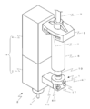
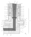
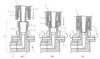
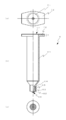
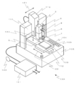
- FIG. 1 It is a perspective view of a liquid material discharge apparatus provided with the attachment / detachment mechanism of this invention. It is side surface sectional drawing of the attachment / detachment mechanism of this invention. It is side surface sectional drawing explaining the effect
- (a) shows when the mounting of the syringe is started,
- (b) shows when the threaded portion is engaged, and
- A) is a top view of a syringe
- (b) is a side half sectional view of the syringe, and (c) is a bottom view of the syringe.
- FIG. 4B is a side view for explaining a component configuration in a mode in which the cartridge cap is attached and detached with a screw portion. It is a perspective view of a coating device provided with the liquid material discharge apparatus of this invention.
- FIG. 1 shows a liquid material discharge device 2 having an attachment / detachment mechanism 1 of the present invention.
- the liquid material discharge device 2 (dispenser) including the attachment / detachment mechanism 1 of the present invention is a mechanical type, and includes a main body 12 including a pump unit 3 and a pump drive unit 4, and a nozzle 5.
- the pump built in the pump unit 3 is a screw type in which a screw having a spiral collar formed in the axial direction of the surface of a rod-like body is rotated, and the collar conveys a liquid material by discharging the liquid by the rotation of the screw.
- a plunger type that moves a desired amount of a plunger that slides in close contact with the inner surface of a measuring portion having a nozzle at the tip and discharges it is exemplified.
- a propulsive force imparting member such as a screw or a plunger communicates with the discharge port and is disposed in the liquid chamber to which the liquid material is supplied, and gives the liquid material a propulsive force necessary for the discharge.
- a nozzle 5 extending vertically is attached to the outlet side of the pump unit 3, and the liquid material 70 is discharged from a discharge port provided at the lower end of the nozzle 5.
- Examples of the driving device for driving the pump built in the pump driving unit 4 include a motor for driving a plunger and a screw, a motor for driving a switching valve, a spring for biasing the plunger, and a pressurized gas supply. Source included.
- the pump unit 3 is in fluid communication with a storage container 6 (syringe) that stores a liquid material, and the liquid material is supplied from the syringe 6.
- a storage container 6 that stores a liquid material
- An elongated upper connection portion 7 extending on the same straight line is formed at the upper end of the syringe 6 illustrated in FIG. 1, and an adapter 8 substantially similar to the upper connection portion 7 can be removably attached.
- a flexible pipe 9 for supplying compressed gas is connected to the adapter 8.
- the lower end of the syringe 6 is provided with an attachment portion 10 having a screw portion 65 formed on the inner surface. The syringe 6 can be attached to the attachment / detachment mechanism 1 by screwing and attaching the attachment portion 10.
- the attachment / detachment mechanism 1 and the metal connecting member 15 are detachably fixed to the pump unit 3 using a fixing member 17 such as a screw.
- the attachment / detachment mechanism 1 and the connecting member 15 may be collectively referred to as a connection member.
- the existing discharge device is of a type in which the attachment / detachment mechanism and the connecting member can be attached / detached with a fixing member such as a screw, the existing attachment / detachment mechanism can be easily replaced by the attachment / detachment mechanism 1 of the present invention. An effect can be obtained.
- FIG. 4 is a side sectional view of the syringe 6.
- the syringe 6 is continuously formed with a storage cylinder 61 in which liquid is stored, an inner cylinder 62 having a smaller diameter than the storage cylinder 61 and formed in communication with the storage space, and an outer peripheral surface of the storage cylinder 61.
- the outer cylinder 63, the connection groove 64 formed between the outer cylinder 63 and the inner cylinder 62, the syringe screw portion 65 formed in the connection groove 64, and the upper connection portion 7 are configured.
- the inner cylinder 62, the outer cylinder 63, the connection groove 64 and the syringe screw part 65 constitute the attachment part 10.
- An outlet channel 66 is provided inside the inner cylinder 62 (see FIG.
- the inner cylinder 62 has a tapered taper, but the inner cylinder 62 may be configured by a cylinder having the same diameter from the upper end to the lower end without the taper.
- the upper connection portion 7 includes a large-diameter opening 71 provided at the center of the upper end portion of the storage cylinder 61 and a flange 72 that extends laterally from the upper end portion of the storage cylinder 61.
- the pair of ridges 72 are symmetrical with respect to the center of the large-diameter opening 71.
- FIGS. 5A and 5B are diagrams showing a syringe 206 according to a modified example, in which FIG. 5A is a side view for explaining a component configuration in a mode of being attached and detached by a cartridge cap and a hook portion, and FIG. 5B is a case where FIG. A side view and (c) are side views explaining the component structure of the aspect which attaches and detaches a cartridge cap with a screw part.
- the liquid material is stored in a resin barrel 261, and a metal or resin connector 210 constituting an attachment portion is connected to the barrel tip.
- the connector 210 includes an inner cylinder having a small diameter opening, an outer cylinder surrounding the inner cylinder, and a screw portion.
- the barrel 251 is inserted into a metal cartridge 263 and used by being covered with a metal cartridge cap 208.
- a hook 209 as shown in FIG. 5A is hooked on a hook groove 207
- a cap screw part 217 and a syringe screw part 219 are fastened as shown in FIG.
- the hook 209 or the syringe screw part 219 constitutes the upper connection part 7.
- a pipe for supplying compressed gas is connected to the cap 208.
- the cartridge type storage container is suitable when the capacity is large (for example, 100 mL or more).
- the resin barrel was illustrated in FIG. 5, a flexible and cylindrical bag as seen with a laminate or metal foil tube as seen with a commercially available adhesive or a commercially available caulking agent or the like.
- the cartridge type can also be applied to the sealed sealant. Even with a cartridge-type storage container, it is possible to produce an effect that the pipe is not twisted when being attached to or detached from the discharge device.
- the “syringe” in this specification includes a cartridge-type storage container.
- the attachment / detachment mechanism 1 of the present invention is mainly composed of a support member 20 connected to the connecting member 15 and a rotation member 40 that is rotatably provided so as to cover the support member 20.
- the support member 20 is a metal member made of a single lump.
- the lower part is called a base part 21, the central part located above the base part 21 is called a support part 22, and the upper part is called an insertion part 23.
- the base 21 has L-shaped flow paths (24, 25) communicating the syringe 6 and the connecting member 15 inside, and is connected to the connecting member 15.
- the support portion 22 is provided on the upper side of the base portion 21 and supports the rotating member 40 with its shoulder portion 28.
- the insertion part 23 is provided on the upper side of the support part 22 and has an upper insertion hole 26 into which the inner cylinder 62 of the syringe 6 is inserted.
- the L-shaped flow path inside the base portion 21 includes a connection-side flow path 24 that communicates with the connecting member flow path 16 and an inlet-side flow path 25 that communicates with the upper insertion hole 26, and the inlet-side flow path 25 and the upper insertion hole 26.
- a mortar-shaped portion 27 is provided between the two.
- the connection-side flow path 24 and the inlet-side flow path 25 communicate with each other through a bent portion.
- the mortar-shaped portion 27 is provided to smoothly reduce the diameter from the upper insertion hole 26 to the inlet-side flow path 25. If the inlet-side channel 25 can be formed to have substantially the same diameter as the outlet channel 66, the mortar-shaped portion 27 may not be provided.
- a base 21 having an upper insertion hole 26 having a shape suitable for various syringe mounting portions is prepared and combined with one or a plurality of types of rotating members 40. May be used.
- the upper insertion hole 26 extending vertically is a flow path having a taper that extends upward, so that the inner circumferential surface 32 of the upper insertion hole is substantially in contact with the outer circumferential surface 67 of the inner cylinder of the syringe 6. It has become. That is, the taper gradient of the upper insertion hole inner peripheral surface 32 shown in the embodiment is substantially the same as the taper gradient of the inner cylinder outer peripheral surface 67 of the syringe 6.
- the liquid material 70 shown in gray in FIG. 2 is supplied from the outlet channel 66 of the syringe 6 toward the connecting member channel 16 in the direction of the arrow (reference numeral 71).
- the support part 22 and the insertion part 23 are continuous concentric cylinders, and the support part 22 has a larger diameter than the insertion part 23, a shoulder part 28 is formed at the connection part between the support part 22 and the insertion part 23.
- a rotary member 40 having through holes (44, 45) is inserted into the support portion 22 and the insertion portion 23, and the rotary member 40 is rotatably supported by the shoulder portion 28 of the support portion 22 having a large diameter. . That is, the support portion 22 and the insertion portion 23 function like a shaft with respect to the rotating member 40.
- the support portion 22 is provided with an annular groove 33 formed in the side surface 29 so as to be recessed.
- the annular groove 33 is fitted with a drop prevention member 51 described later.
- the metal or resin-made rotating member 40 includes an operation portion 41 positioned below, a trunk portion 42 positioned at the center, and a convex portion 43 positioned above.
- the body portion 42 and the convex portion 43 may be collectively referred to as a raised portion.
- the operation portion 41 is a disk-shaped member, and a recess 45 that communicates with the through hole 44 is provided in the central portion of the bottom surface 48.
- the body portion 42 is a disk-shaped member having a smaller diameter than the operation portion 41, and a through hole 44 is provided at the center.
- the rotating member 40 is positioned by being inserted into the insertion portion 23 of the support member 20 from the bottom surface side of the recess 45 and fitting the support portion 22 into the recess 45.
- the through holes (44, 45) into which the support portion 22 and the insertion portion 23, which are stepped cylinders, are closely fitted are formed so as to be concentric with the central axis of the rotating member 40.
- the shoulder 28 is formed at a height at which a slight gap is formed between the bottom surface 48 of the rotating member and the base upper surface 30 and the rotating operation of the rotating member 40 is not hindered.
- a side insertion hole 47 that penetrates into the recess 45 is provided on the side surface 50 of the operation unit 41.
- the side insertion hole 47 is provided at the same height as the annular groove 33 of the support member 20, so that the rotation member 40 does not come off the support member 20 by inserting the removal prevention member 51 from the side insertion hole 47.
- the slip prevention member 51 is a rod-like member having a length that is longer than the total length of the side insertion hole 47 and shorter than the total length of the side insertion hole 47 and the depth of the annular groove 33.
- the diameter of the removal preventing member 51 is slightly smaller than the vertical width (from the upper surface to the lower surface) of the annular groove 33 of the support portion 22, so that the rotation of the rotating member 40 is not hindered.
- the side insertion hole 47 of the operation unit 41 is formed with a thread groove that engages with the removal prevention member 51 or is fitted so that the removal prevention member 51 can be firmly fixed.
- the side insertion hole 47 and the removal preventing member 51 are provided at two locations facing the rotation shaft, but the present invention is not limited to this.
- the side insertion holes 47 and the removal preventing members 51 may be provided at, for example, three locations (Y-shaped when viewed from the top) and four locations (cross-shaped when viewed from the top) at regular intervals.
- the shape of the operation unit 41 is not limited to a circular shape when viewed from above.
- the I shape when viewed from the top in the case of two locations where the side portion insertion holes 47 face each other), May be three), and may be cross-shaped when viewed from above (when there are four side insertion holes 47).
- the surface of the operation unit side surface 50 is preferably provided with a non-slip function in order to make the operation easier. For example, processing such as knurling, satin or sandblasting may be performed.
- the shape of the trunk portion 42 is not limited to a circular shape when viewed from above, and may be, for example, the same diameter as the convex portion 43 (that is, the convex portion 43 may be raised immediately from the operation portion 41 without providing the trunk portion 42. ).
- a screw portion 46 is formed on the outer peripheral surface of the convex portion 43 and engages with a screw portion 65 formed on the inner surface of the attachment portion 10 of the syringe 6.
- the threaded portion (65, 46) is preferably a double thread or luer connector.
- the upper end surface 49 of the rotating member and the upper end surface 31 of the support member do not necessarily have to be on the same plane, but the one on the same plane is a measure of whether the rotating member 40 is fitted to the correct position. This is preferable because it can be performed.
- drum 42, and the convex part 43 may be produced integrally, and may combine several members.
- the discharge device 2 is mounted on a desktop type coating device 100, and the discharge device 2 and the work table 103 are moved relative to each other by an XYZ axis driving device (111, 112, 113), and the work 106 is placed on the work 106.
- XYZ axis driving device 111, 112, 113
- the work 106 is placed on the work 106.
- Reference numeral 111 denotes an X-axis driving device that enables relative movement in the X direction (reference numeral 121)
- reference numeral 112 denotes a Y-axis driving device that enables relative movement in the Y direction (reference numeral 122)
- reference numeral 113 denotes a Z direction ( This Z-axis drive device enables the relative movement to reference numeral 123).
- a servo motor for example, a servo motor, a combination of a stepping motor and a ball screw, a linear motor, or the like can be used.
- These driving devices are arranged on a gantry 105 that incorporates a coating control unit (not shown) that controls the operation of the XYZ axis driving device.
- An operation button 104 is provided on the upper surface of the gantry 105.
- a dispense controller 101 is installed beside the gantry 105, and the compressed gas from the compressed gas source 102 is supplied to the syringe 6 under desired conditions.
- the coating apparatus 100 may be provided with a plurality of ejection devices 2.
- the attachment / detachment mechanism 1 of the present invention has a particularly advantageous effect in a desktop type coating apparatus having a strong demand for space saving, but it is naturally applicable to a non-desktop type coating apparatus.
- FIG. 3 is an explanatory diagram for explaining the operation when the syringe 6 is mounted in the attachment / detachment mechanism 1 of the present invention.
- A First, the inner cylinder 62 of the syringe 6 is inserted into the upper insertion hole 26 of the support member 20, and the syringe 6 is lowered until the screw portion 65 of the syringe 6 and the screw portion 46 of the rotating member 40 contact each other (FIG. 3). (See (a)).
- the syringe 6 will not come off. Further, the taper portions (67, 32) act like a seal, and the liquid material 70 does not leak from this portion. That is, it is not necessary to separately provide a sealing member such as an O-ring. In addition, although not shown in figure, when removing the syringe 6, what is necessary is just to perform operation reverse to the said operation. Also at this time, the syringe 6 can be moved (raised when removed) simply by rotating the rotating member 40 without rotating the syringe 6.
- the attachment / detachment mechanism of the present invention can attach / detach the syringe by rotating the rotating member without rotating the syringe, prevent twisting of the pipe connected to the syringe, or the syringe itself. Can prevent damage. Further, the overall width of the discharge device can be kept small by adjusting the orientation of the upper connecting portion and the adapter.
Landscapes
- Engineering & Computer Science (AREA)
- General Engineering & Computer Science (AREA)
- Mechanical Engineering (AREA)
- Coating Apparatus (AREA)
- Quick-Acting Or Multi-Walled Pipe Joints (AREA)
Priority Applications (8)
| Application Number | Priority Date | Filing Date | Title |
|---|---|---|---|
| MYPI2017700301A MY182987A (en) | 2014-07-30 | 2015-07-17 | Syringe attachment/detachment mechanism and device provided with mechanism |
| CN201580041299.8A CN106573269B (zh) | 2014-07-30 | 2015-07-17 | 注射器装卸机构及具备该机构的装置 |
| EP15826303.8A EP3175928B1 (en) | 2014-07-30 | 2015-07-17 | Syringe attachment/detachment mechanism and device provided with mechanism |
| ES15826303T ES2774088T3 (es) | 2014-07-30 | 2015-07-17 | Mecanismo de conexión / desconexión de jeringas y dispositivo provisto de dicho mecanismo |
| US15/329,359 US10441967B2 (en) | 2014-07-30 | 2015-07-17 | Syringe attachment/detachment mechanism and device provided with mechanism |
| PL15826303T PL3175928T3 (pl) | 2014-07-30 | 2015-07-17 | Mocujący/odłączający strzykawkę mechanizm oraz urządzenie zaopatrzone w mechanizm |
| SG11201700494VA SG11201700494VA (en) | 2014-07-30 | 2015-07-17 | Syringe attachment/detachment mechanism and device provided with mechanism |
| KR1020177004938A KR102306481B1 (ko) | 2014-07-30 | 2015-07-17 | 시린지 착탈 기구 및 상기 기구를 구비하는 장치 |
Applications Claiming Priority (2)
| Application Number | Priority Date | Filing Date | Title |
|---|---|---|---|
| JP2014154387A JP6358885B2 (ja) | 2014-07-30 | 2014-07-30 | シリンジ着脱機構および当該機構を備える装置 |
| JP2014-154387 | 2014-07-30 |
Publications (1)
| Publication Number | Publication Date |
|---|---|
| WO2016017453A1 true WO2016017453A1 (ja) | 2016-02-04 |
Family
ID=55217357
Family Applications (1)
| Application Number | Title | Priority Date | Filing Date |
|---|---|---|---|
| PCT/JP2015/070504 Ceased WO2016017453A1 (ja) | 2014-07-30 | 2015-07-17 | シリンジ着脱機構および当該機構を備える装置 |
Country Status (13)
| Country | Link |
|---|---|
| US (1) | US10441967B2 (enExample) |
| EP (1) | EP3175928B1 (enExample) |
| JP (1) | JP6358885B2 (enExample) |
| KR (1) | KR102306481B1 (enExample) |
| CN (1) | CN106573269B (enExample) |
| ES (1) | ES2774088T3 (enExample) |
| HU (1) | HUE048678T2 (enExample) |
| MY (1) | MY182987A (enExample) |
| PL (1) | PL3175928T3 (enExample) |
| PT (1) | PT3175928T (enExample) |
| SG (1) | SG11201700494VA (enExample) |
| TW (1) | TWI667074B (enExample) |
| WO (1) | WO2016017453A1 (enExample) |
Cited By (1)
| Publication number | Priority date | Publication date | Assignee | Title |
|---|---|---|---|---|
| US11684725B2 (en) | 2018-12-19 | 2023-06-27 | Fenwal, Inc. | Disposable syringe for use with pneumatic drivers |
Families Citing this family (17)
| Publication number | Priority date | Publication date | Assignee | Title |
|---|---|---|---|---|
| JP6452147B2 (ja) * | 2015-01-19 | 2019-01-16 | 武蔵エンジニアリング株式会社 | 液体材料吐出装置 |
| JP6778426B2 (ja) * | 2016-09-20 | 2020-11-04 | 武蔵エンジニアリング株式会社 | 液体材料吐出装置 |
| KR102341945B1 (ko) * | 2017-03-13 | 2021-12-22 | 주식회사 탑 엔지니어링 | 기판 처리 장치 |
| MY200658A (en) | 2017-05-25 | 2024-01-09 | Musashi Eng Inc | Liquid material application apparatus and liquid material application method |
| KR102049000B1 (ko) * | 2017-07-19 | 2019-11-26 | 안동대학교 산학협력단 | 3차원 인공지지체 제조 장치 |
| KR101974747B1 (ko) * | 2017-10-24 | 2019-05-02 | (주)제이월드텍 | 진공믹서기 |
| KR102019591B1 (ko) * | 2018-02-08 | 2019-09-06 | 문병휘 | 시린지의 코트부재 및 이를 이용한 시린지의 재사용방법 |
| JP6471258B2 (ja) * | 2018-06-04 | 2019-02-13 | 武蔵エンジニアリング株式会社 | 液体材料塗布装置および液体材料塗布方法 |
| JP7093285B2 (ja) * | 2018-10-11 | 2022-06-29 | 株式会社Subaru | シール剤吐出装置 |
| JP7037734B2 (ja) * | 2019-09-05 | 2022-03-17 | 日立金属株式会社 | 熱電変換モジュールの製造方法 |
| JP7489092B2 (ja) * | 2020-04-10 | 2024-05-23 | 兵神装備株式会社 | 液剤塗布装置 |
| JP7282060B2 (ja) * | 2020-04-17 | 2023-05-26 | 孝志 上市 | メッキ装置 |
| CN112318099A (zh) * | 2020-10-23 | 2021-02-05 | 胡仓铜 | 一种汽车防尘总成件的装配设备 |
| WO2022216121A1 (ko) * | 2021-04-09 | 2022-10-13 | 엘지전자 주식회사 | 디스펜서 및 그를 갖는 잉크 도포 장비 |
| USD1045074S1 (en) * | 2021-08-20 | 2024-10-01 | Musashi Engineering, Inc. | Tube adapter for liquid precision discharge machine |
| JP2024100053A (ja) * | 2023-01-13 | 2024-07-26 | ブラザー工業株式会社 | 液体供給装置 |
| EP4579077A1 (en) * | 2023-12-27 | 2025-07-02 | Fenwal, Inc. | Fluid processing system with high pressure pneumatic syringe pump |
Citations (7)
| Publication number | Priority date | Publication date | Assignee | Title |
|---|---|---|---|---|
| JPS53107327U (enExample) * | 1977-02-04 | 1978-08-29 | ||
| JPH09505876A (ja) * | 1994-09-15 | 1997-06-10 | エンヴァイロン・プロダクツ・インコーポレーテッド | パイプの継手組立体、システム及び方法 |
| JP2000055273A (ja) * | 1998-08-10 | 2000-02-22 | Kyouseki Sangyo Kk | 自己シール型一重管継手 |
| JP2002509231A (ja) * | 1998-01-20 | 2002-03-26 | オプティマイズ・テクノロジーズ・インコーポレイテッド | 4分の1ターン迅速接続フィッティング |
| JP2009539607A (ja) * | 2006-06-13 | 2009-11-19 | ノードソン コーポレーション | 液体吐出シリンジ |
| JP2013052350A (ja) * | 2011-09-05 | 2013-03-21 | Shibaura Mechatronics Corp | ペースト吐出装置、ペースト塗布装置及びペースト塗布方法 |
| JP2013107034A (ja) * | 2011-11-21 | 2013-06-06 | Panasonic Corp | 液剤塗布装置及び液剤塗布装置における空気抜き方法 |
Family Cites Families (11)
| Publication number | Priority date | Publication date | Assignee | Title |
|---|---|---|---|---|
| US5010841A (en) | 1989-05-23 | 1991-04-30 | Mcdonnell Douglas Corporation | Rotating sealant applicator |
| CN1124661A (zh) * | 1994-12-13 | 1996-06-19 | 斋藤嘉邦 | 注射器及注射器的装配方法 |
| WO2001044707A1 (en) * | 1999-12-15 | 2001-06-21 | Oystertec Plc | Hydraulic connectors |
| JP3570422B2 (ja) | 2002-11-26 | 2004-09-29 | 日立化成工業株式会社 | ディスペンサー用注射筒及びペースト状接着剤 |
| JP2008068245A (ja) | 2006-09-11 | 2008-03-27 | Minoru Nakamura | 補給方式 |
| JP2010022881A (ja) * | 2007-03-30 | 2010-02-04 | Musashi Eng Co Ltd | 液材吐出装置および液材吐出方法 |
| US9156054B2 (en) * | 2007-05-18 | 2015-10-13 | Musashi Engineering, Inc. | Method and apparatus for discharging liquid material |
| USD738495S1 (en) | 2013-08-23 | 2015-09-08 | Nordson Corporation | Piston for a liquid dispensing syringe |
| KR100961759B1 (ko) * | 2008-06-25 | 2010-06-07 | 주식회사 프로텍 | 레진도포장치 |
| CN103491925A (zh) * | 2011-02-13 | 2014-01-01 | 艾力克·严 | 液体输送系统 |
| JP2013055096A (ja) | 2011-09-01 | 2013-03-21 | Panasonic Corp | ペースト塗布装置 |
-
2014
- 2014-07-30 JP JP2014154387A patent/JP6358885B2/ja active Active
-
2015
- 2015-07-17 PT PT158263038T patent/PT3175928T/pt unknown
- 2015-07-17 KR KR1020177004938A patent/KR102306481B1/ko active Active
- 2015-07-17 HU HUE15826303A patent/HUE048678T2/hu unknown
- 2015-07-17 SG SG11201700494VA patent/SG11201700494VA/en unknown
- 2015-07-17 ES ES15826303T patent/ES2774088T3/es active Active
- 2015-07-17 MY MYPI2017700301A patent/MY182987A/en unknown
- 2015-07-17 PL PL15826303T patent/PL3175928T3/pl unknown
- 2015-07-17 WO PCT/JP2015/070504 patent/WO2016017453A1/ja not_active Ceased
- 2015-07-17 US US15/329,359 patent/US10441967B2/en active Active
- 2015-07-17 CN CN201580041299.8A patent/CN106573269B/zh active Active
- 2015-07-17 EP EP15826303.8A patent/EP3175928B1/en active Active
- 2015-07-29 TW TW104124529A patent/TWI667074B/zh active
Patent Citations (7)
| Publication number | Priority date | Publication date | Assignee | Title |
|---|---|---|---|---|
| JPS53107327U (enExample) * | 1977-02-04 | 1978-08-29 | ||
| JPH09505876A (ja) * | 1994-09-15 | 1997-06-10 | エンヴァイロン・プロダクツ・インコーポレーテッド | パイプの継手組立体、システム及び方法 |
| JP2002509231A (ja) * | 1998-01-20 | 2002-03-26 | オプティマイズ・テクノロジーズ・インコーポレイテッド | 4分の1ターン迅速接続フィッティング |
| JP2000055273A (ja) * | 1998-08-10 | 2000-02-22 | Kyouseki Sangyo Kk | 自己シール型一重管継手 |
| JP2009539607A (ja) * | 2006-06-13 | 2009-11-19 | ノードソン コーポレーション | 液体吐出シリンジ |
| JP2013052350A (ja) * | 2011-09-05 | 2013-03-21 | Shibaura Mechatronics Corp | ペースト吐出装置、ペースト塗布装置及びペースト塗布方法 |
| JP2013107034A (ja) * | 2011-11-21 | 2013-06-06 | Panasonic Corp | 液剤塗布装置及び液剤塗布装置における空気抜き方法 |
Non-Patent Citations (1)
| Title |
|---|
| See also references of EP3175928A4 * |
Cited By (2)
| Publication number | Priority date | Publication date | Assignee | Title |
|---|---|---|---|---|
| US11684725B2 (en) | 2018-12-19 | 2023-06-27 | Fenwal, Inc. | Disposable syringe for use with pneumatic drivers |
| US11904147B2 (en) | 2018-12-19 | 2024-02-20 | Fenwal, Inc. | Methods and systems for mating disposable syringes with pneumatic drivers without breaking sterility |
Also Published As
| Publication number | Publication date |
|---|---|
| SG11201700494VA (en) | 2017-03-30 |
| KR20170038006A (ko) | 2017-04-05 |
| KR102306481B1 (ko) | 2021-09-28 |
| TWI667074B (zh) | 2019-08-01 |
| MY182987A (en) | 2021-02-05 |
| EP3175928B1 (en) | 2020-01-01 |
| US20170225188A1 (en) | 2017-08-10 |
| CN106573269B (zh) | 2019-05-14 |
| EP3175928A4 (en) | 2018-05-16 |
| US10441967B2 (en) | 2019-10-15 |
| HUE048678T2 (hu) | 2020-08-28 |
| PT3175928T (pt) | 2020-01-28 |
| ES2774088T3 (es) | 2020-07-16 |
| TW201607622A (zh) | 2016-03-01 |
| JP2016030242A (ja) | 2016-03-07 |
| CN106573269A (zh) | 2017-04-19 |
| EP3175928A1 (en) | 2017-06-07 |
| PL3175928T3 (pl) | 2020-06-29 |
| JP6358885B2 (ja) | 2018-07-18 |
Similar Documents
| Publication | Publication Date | Title |
|---|---|---|
| JP6358885B2 (ja) | シリンジ着脱機構および当該機構を備える装置 | |
| JP6452147B2 (ja) | 液体材料吐出装置 | |
| CN104159676B (zh) | 液体定量吐出装置、其涂布装置及液体定量吐出方法 | |
| TWI402104B (zh) | Liquid material discharge device | |
| JP2017523914A (ja) | 供給システム用の遠隔バルク給送システム及び供給システムに粘性材料を供給する方法 | |
| KR20190057061A (ko) | 액체 재료 토출 장치 | |
| JP2020131182A (ja) | 吐出装置及び産業用ロボット | |
| JP2017527436A (ja) | ディスペンサ用の弁座 | |
| EP3069796B1 (en) | Zero waste color change system | |
| JP2003164783A (ja) | 液体吐出用ディスペンサ | |
| JP2013052350A (ja) | ペースト吐出装置、ペースト塗布装置及びペースト塗布方法 | |
| JP2020044473A (ja) | カートリッジ吐出装置及び栓構造 | |
| HK1234700B (zh) | 注射器装卸机构及具备该机构的装置 | |
| HK1234700A1 (en) | Syringe attachment/detachment mechanism and device provided with mechanism | |
| CN107442315B (zh) | 粘性液体排出设备 | |
| CN108882972B (zh) | 粉末室和用于粉末室的工作台 | |
| JP6233159B2 (ja) | 塗布装置 | |
| JP4927920B2 (ja) | 液状物の吐出装置 | |
| HK1238603A1 (en) | Liquid material discharge apparatus | |
| CN113198687A (zh) | 一种应用于点胶设备的补胶装置 | |
| KR20210022267A (ko) | 팝너트 체결 장치 | |
| HK1238603B (zh) | 液体材料吐出装置 |
Legal Events
| Date | Code | Title | Description |
|---|---|---|---|
| 121 | Ep: the epo has been informed by wipo that ep was designated in this application |
Ref document number: 15826303 Country of ref document: EP Kind code of ref document: A1 |
|
| NENP | Non-entry into the national phase |
Ref country code: DE |
|
| REEP | Request for entry into the european phase |
Ref document number: 2015826303 Country of ref document: EP |
|
| WWE | Wipo information: entry into national phase |
Ref document number: 2015826303 Country of ref document: EP |
|
| ENP | Entry into the national phase |
Ref document number: 20177004938 Country of ref document: KR Kind code of ref document: A |