EP3175928B1 - Syringe attachment/detachment mechanism and device provided with mechanism - Google Patents
Syringe attachment/detachment mechanism and device provided with mechanism Download PDFInfo
- Publication number
- EP3175928B1 EP3175928B1 EP15826303.8A EP15826303A EP3175928B1 EP 3175928 B1 EP3175928 B1 EP 3175928B1 EP 15826303 A EP15826303 A EP 15826303A EP 3175928 B1 EP3175928 B1 EP 3175928B1
- Authority
- EP
- European Patent Office
- Prior art keywords
- syringe
- attachment
- detachment mechanism
- discharge device
- discharge
- Prior art date
- Legal status (The legal status is an assumption and is not a legal conclusion. Google has not performed a legal analysis and makes no representation as to the accuracy of the status listed.)
- Active
Links
Images


Classifications
-
- B—PERFORMING OPERATIONS; TRANSPORTING
- B05—SPRAYING OR ATOMISING IN GENERAL; APPLYING FLUENT MATERIALS TO SURFACES, IN GENERAL
- B05C—APPARATUS FOR APPLYING FLUENT MATERIALS TO SURFACES, IN GENERAL
- B05C11/00—Component parts, details or accessories not specifically provided for in groups B05C1/00 - B05C9/00
- B05C11/11—Vats or other containers for liquids or other fluent materials
-
- B—PERFORMING OPERATIONS; TRANSPORTING
- B05—SPRAYING OR ATOMISING IN GENERAL; APPLYING FLUENT MATERIALS TO SURFACES, IN GENERAL
- B05C—APPARATUS FOR APPLYING FLUENT MATERIALS TO SURFACES, IN GENERAL
- B05C5/00—Apparatus in which liquid or other fluent material is projected, poured or allowed to flow on to the surface of the work
- B05C5/02—Apparatus in which liquid or other fluent material is projected, poured or allowed to flow on to the surface of the work the liquid or other fluent material being discharged through an outlet orifice by pressure, e.g. from an outlet device in contact or almost in contact, with the work
- B05C5/0208—Apparatus in which liquid or other fluent material is projected, poured or allowed to flow on to the surface of the work the liquid or other fluent material being discharged through an outlet orifice by pressure, e.g. from an outlet device in contact or almost in contact, with the work for applying liquid or other fluent material to separate articles
- B05C5/0212—Apparatus in which liquid or other fluent material is projected, poured or allowed to flow on to the surface of the work the liquid or other fluent material being discharged through an outlet orifice by pressure, e.g. from an outlet device in contact or almost in contact, with the work for applying liquid or other fluent material to separate articles only at particular parts of the articles
-
- B—PERFORMING OPERATIONS; TRANSPORTING
- B05—SPRAYING OR ATOMISING IN GENERAL; APPLYING FLUENT MATERIALS TO SURFACES, IN GENERAL
- B05C—APPARATUS FOR APPLYING FLUENT MATERIALS TO SURFACES, IN GENERAL
- B05C11/00—Component parts, details or accessories not specifically provided for in groups B05C1/00 - B05C9/00
-
- B—PERFORMING OPERATIONS; TRANSPORTING
- B05—SPRAYING OR ATOMISING IN GENERAL; APPLYING FLUENT MATERIALS TO SURFACES, IN GENERAL
- B05C—APPARATUS FOR APPLYING FLUENT MATERIALS TO SURFACES, IN GENERAL
- B05C13/00—Means for manipulating or holding work, e.g. for separate articles
-
- B—PERFORMING OPERATIONS; TRANSPORTING
- B05—SPRAYING OR ATOMISING IN GENERAL; APPLYING FLUENT MATERIALS TO SURFACES, IN GENERAL
- B05C—APPARATUS FOR APPLYING FLUENT MATERIALS TO SURFACES, IN GENERAL
- B05C5/00—Apparatus in which liquid or other fluent material is projected, poured or allowed to flow on to the surface of the work
- B05C5/02—Apparatus in which liquid or other fluent material is projected, poured or allowed to flow on to the surface of the work the liquid or other fluent material being discharged through an outlet orifice by pressure, e.g. from an outlet device in contact or almost in contact, with the work
-
- F—MECHANICAL ENGINEERING; LIGHTING; HEATING; WEAPONS; BLASTING
- F16—ENGINEERING ELEMENTS AND UNITS; GENERAL MEASURES FOR PRODUCING AND MAINTAINING EFFECTIVE FUNCTIONING OF MACHINES OR INSTALLATIONS; THERMAL INSULATION IN GENERAL
- F16L—PIPES; JOINTS OR FITTINGS FOR PIPES; SUPPORTS FOR PIPES, CABLES OR PROTECTIVE TUBING; MEANS FOR THERMAL INSULATION IN GENERAL
- F16L37/00—Couplings of the quick-acting type
- F16L37/24—Couplings of the quick-acting type in which the connection is made by inserting one member axially into the other and rotating it to a limited extent, e.g. with bayonet-action
-
- F—MECHANICAL ENGINEERING; LIGHTING; HEATING; WEAPONS; BLASTING
- F16—ENGINEERING ELEMENTS AND UNITS; GENERAL MEASURES FOR PRODUCING AND MAINTAINING EFFECTIVE FUNCTIONING OF MACHINES OR INSTALLATIONS; THERMAL INSULATION IN GENERAL
- F16L—PIPES; JOINTS OR FITTINGS FOR PIPES; SUPPORTS FOR PIPES, CABLES OR PROTECTIVE TUBING; MEANS FOR THERMAL INSULATION IN GENERAL
- F16L19/00—Joints in which sealing surfaces are pressed together by means of a member, e.g. a swivel nut, screwed on, or into, one of the joint parts
- F16L19/04—Joints in which sealing surfaces are pressed together by means of a member, e.g. a swivel nut, screwed on, or into, one of the joint parts using additional rigid rings, sealing directly on at least one pipe end, which is flared either before or during the making of the connection
Definitions
- the present invention relates to a mechanism enabling a liquid material reservoir (syringe) for a discharge device to be easily attached and detached, and further relates to a device provided with the mechanism. More particularly, the present invention relates to a mechanism for a connection portion with respect to a pump that is used to discharge a liquid material, and further relates to a device provided with the mechanism.
- Known discharge devices for discharging a liquid material from a discharge port of a nozzle in communication with a liquid material reservoir (syringe) are mainly divided into the air type and the mechanical type.
- An air type dispenser mountable to an XYZ-axis drive device is generally constituted such that a nozzle is directly mounted to the lower end side of the syringe, and that compressed gas is supplied from the upper end side of the syringe to discharge the liquid material from the nozzle.
- a mechanical type dispenser is generally constituted such that a pump (e.g., a screw pump or a plunger pump) is mounted to the lower side of the syringe, and that the liquid material is discharged from a nozzle, which is mounted to a pump outlet end, by the action of the pump.
- a tubing line through which the compressed gas is supplied to the syringe is also connected to the opposite side (upper side) relative to the side to which the pump is connected, as in the case of the air type, for the purpose of assisting supply of the liquid material to the pump.
- the syringe and the pump are connected, for example, by disposing a block-shaped connection member (see, e.g., Patent Document 1), or by employing a tubing line (i.e., a tube or a pipe) (see, e.g., Patent Document 2).
- a block-shaped connection member see, e.g., Patent Document 1
- a tubing line i.e., a tube or a pipe
- a general syringe includes a barrel portion having a cylindrical shape, a screw portion formed at one end of the syringe, and a flange portion formed at the other end.
- a nozzle or a pump is connected to the syringe on the side where the screw portion is formed, and a tubing line (tube) through which compressed gas is supplied is connected through an adapter to the syringe on the side where the flange portion is formed.
- Japanese Patent Laid-Open Publication No. 2009-539607 discloses the preamble of claim 1.
- a syringe body In order to attach the syringe, which includes the screw portion formed at the one end thereof, to a connection member extending laterally from a body of a discharge device, a syringe body needs to be rotated for the attachment through screwing.
- the syringe is rotated after attaching the adapter to which the tube for supplying the compressed gas is connected, there is a problem that the tube twisted with the rotation of the syringe may be tangled or damaged.
- a relatively weak portion of the syringe, such as the screw portion may be deformed or damaged with a motion of the twisted tube restoring to its original state.
- the syringe is not circular when viewed from above, and the upper connection part has a shape protruding from the cylindrical barrel body (so as to form the flange portion in an elongate hexagonal or more polygonal shape, or the flange portion substantially in an elliptic or rectangular shape, for example).
- orientation the upper connection part (flange portion) and the adapter are fixed depend on how a screw portion of the connection member is formed (it is technically difficult to machine thread grooves in metal-made connection members in a manner of always specifying the same start point for each of the thread grooves).
- variations occur in formation states of the screw portions depending on makers.
- the flange portion and the adapter are sometimes not positioned in the desired orientation.
- the flange portion and the adapter may be protruded in a direction perpendicular to the connection member, and that an overall width of the discharge device may be increased.
- Such a problem is especially serious in the case of arranging the plurality of discharge devices (dispensers) side by side.
- an object of the present invention is to provide a syringe attachment/detachment mechanism and a device provided with the mechanism, which can solve the above-mentioned problems.
- a commercially available syringe is made of a resin material, and it has an elongate upper connection part (flange portion) that extends in one straight line.
- a custom-ordered syringe has to be used to make the upper connection part (flange portion) rotatable relative to a barrel of the syringe.
- the custom-ordered syringe is problematic in increasing the cost.
- the inventor has designed, through intensive studies, a mechanism enabling a syringe, which may be the commercially available syringe, to be attached to the discharge device through screwing without rotating the syringe.
- the present invention is constituted by the following technical features.
- a syringe attachment/detachment mechanism (1) for a discharge device to which a syringe (6, 206) including an attachment part (10) and an upper connection part (7) is attached through screwing wherein the attachment part (10) includes an inner cylindrical portion (62) having a small-diameter opening (68), an outer cylindrical portion (63) surrounding the inner cylindrical portion (62), and a screw portion (65), the attachment/detachment mechanism (1) includes a support member (20) including a cylindrical insertion portion (23) into which the inner cylindrical portion (62) is inserted, and having a channel (24, 25) formed therein for communication between the small-diameter opening and a nozzle of the discharge device, a rotation member (40) including a screw portion (46) engaging with the screw portion (65) of the attachment part is provided to be rotatably fitted over the insertion portion (32), and the syringe is attached with rotation of the rotation member (40).
- the support member (20) may have an annular groove formed in a lateral peripheral surface thereof
- the rotation member (40) may have a lateral insertion hole positioned in an opposing relation to the annular groove
- the attachment/detachment mechanism may further include one or more slip-off preventive members each extending through both the lateral insertion hole and the annular groove.
- the inner cylindrical portion (62) may have a tapered outer peripheral surface gradually thinning toward the small-diameter opening (68), and the insertion portion (23) may be provided with an upper insertion hole (26) having a tapered inner peripheral surface that is contacted with the tapered outer peripheral surface of the inner cylindrical portion (62).
- the support member (20) may include a support portion (22) having a larger diameter than the insertion portion (23), and the rotation member (40) may include a raised portion (42, 43) having a through-hole (44) into which the insertion portion (23) is inserted, an operating portion (41) having a larger diameter than the raised portion, and a recess (45) into which the support portion (22) is fitted.
- a lateral surface of the operating portion (41) is treated with a process for anti-slipping.
- a discharge device (2) comprising a nozzle having a discharge port, a liquid chamber that is communicated with the discharge port, and that is supplied with a liquid material, a main body (12) including the liquid chamber formed therein, a coupling member (15) connected to the main body and including a channel (16) formed therein to be communicated with the nozzle, a propulsion force applying member arranged in the liquid chamber and giving a propulsion force necessary for discharge to the liquid material, a propulsion-force applying member drive source for operating the propulsion force applying member, and a discharge control unit, wherein the discharge device includes the above-described syringe attachment/detachment mechanism according to the present invention.
- an application apparatus comprising the above-described discharge device according to the present invention, a compressed gas source (102) that supplies compressed gas for applying pressure to a syringe, the syringe (6, 206) including an attachment part (10) and an upper connection part (7), and being attached to the syringe attachment/detachment mechanism through screwing, an adapter (8) connected to a tube that communicates the syringe and the compressed gas source with each other, and being mounted to the upper connection part, a worktable (103) on which an application object is placed, XYZ-axis drive devices (111, 112, 113) that relatively move the discharge device (2) and the worktable (103), and an application control unit that controls operations of the XYZ-axis drive devices.
- the upper connection part of the syringe is constituted by an elongate flange (72) extending in one straight line.
- the discharge device (2) may be constituted by the plurality of discharge devices arranged in such a state that the coupling members (15) are positioned parallel to each other.
- the syringe can be easily attached to and detached from the discharge device without causing twisting of a tube through which compressed gas is supplied, the tube and the syringe can be avoided from being damaged.
- an overall width of the discharge device i.e., a width thereof in a direction perpendicular to a coupling member
- an overall width of the discharge device can be held relatively small by adjusting the orientation of the upper connection part and the adapter.
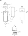
- Fig. 1 illustrates a liquid material discharge device 2 provided with an attachment/detachment mechanism 1 according to the present invention.
- the liquid material discharge device 2 (dispenser) provided with the attachment/detachment mechanism 1 according to the present invention is of the mechanical type, and it includes a main body 12 constituted by a pump section 3 and a pump drive section 4, and a nozzle 5.
- a pump incorporated in the pump section 3 may be of, for example, the screw type rotating a screw that includes a spiral blade formed on a surface of a rod-like member along an axial direction, and feeding a liquid material by the blade with rotation of the screw, thus discharging the liquid material, or the plunger type moving a plunger, which slides in close contact with an inner surface of a metering portion including a nozzle at its tip end, through a desired distance, thus discharging the liquid material.
- a propulsion force applying member e.g., the screw or the plunger, is arranged in a liquid chamber, which is communicated with a discharge port and to which the liquid material is supplied, in order to give the liquid material with a propulsion force necessary for discharging the liquid material.
- the nozzle 5 extending in a vertical direction is mounted to the outlet side of the pump section 3, and the liquid material 70 is discharged from the discharge port that is provided at a lower end of the nozzle 5.
- a drive device for driving the pump incorporated in the pump drive section 4 includes, for example, a motor for driving the plunger or the screw, a motor for driving a switching valve, a spring for biasing the plunger, and a compressed gas supply source.
- the pump section 3 is in fluid-communication with a reservoir 6 (syringe) that stores the liquid material, and the liquid material is supplied to the pump section 3 from the syringe 6.
- a reservoir 6 that stores the liquid material
- the liquid material is supplied to the pump section 3 from the syringe 6.
- an elongate upper connection part 7 extending in one straight line is formed, and an adapter 8 having a substantially similar shape to that of the upper connection part 7 can be attached to the upper connection part 7 in a detachable manner.
- the adapter 8 is connected to a flexible tube 9 through which compressed gas is supplied.
- an attachment part 10 including a screw portion 65 formed in its inner surface is provided at a lower end of the syringe 6.
- the syringe 6 can be attached to the attachment/detachment mechanism 1 by fitting the attachment part 10 through screwing.
- the attachment/detachment mechanism 1 and a metal-made coupling member 15 are fixed to the pump section 3 in a detachable manner with use of fixing members 17 such as screws.
- the attachment/detachment mechanism 1 and the coupling member 15 are collectively called a connection member in some cases.
- an existing discharge device is of the type that an attachment/detachment mechanism and a coupling member can be attached and detached with use of fixing members such as screws, the advantageous effects of the present invention can be easily obtained by replacing the existing attachment/detachment mechanism with the attachment/detachment mechanism 1 of the present invention.
- Fig. 4 is a side sectional view of the syringe 6.
- the syringe 6 includes a storage cylinder 61, an inner cylindrical portion 62, an outer cylindrical portion 63, a connection groove 64, a syringe screw portion 65, and the upper connection part 7.
- the storage cylinder 61 stores the liquid material.
- the inner cylindrical portion 62 has a smaller diameter than the storage cylinder 61 and forms a storage space inside by communicating with the storage cylinder 61.
- the outer cylindrical portion 63 is formed in continuity with an outer peripheral surface of the storage cylinder 61.
- the connection groove 64 is formed between the outer cylindrical portion 63 and the inner cylindrical portion 62.
- the syringe screw portion 65 is formed in the connection groove 64.
- the inner cylindrical portion 62, the outer cylindrical portion 63, the connection groove 64, and the syringe screw portion 65 constitute the attachment part 10.
- An outlet channel 66 is formed inside the inner cylindrical portion 62 (see Fig. 2 ), and a small-diameter opening 68 is formed at a lower end of the inner cylindrical portion 62.
- the inner cylindrical portion 62 has a tapered shape gradually thinning toward a tip end.
- the inner cylindrical portion 62 may be constituted as a non-tapered cylindrical portion having the same diameter from an upper end to a lower end.
- the upper connection part 7 is constituted by a large-diameter opening 71 formed at a center of an upper end portion of the storage cylinder 61, and a pair of flanges 72 extending from the upper end portion of the storage cylinder 61 laterally to the right and the left.
- the pair of flanges 72 have a symmetrical shape with respect to the center of the large-diameter opening 71.
- Fig. 5 illustrates a syringe 206 according to a modification. More specifically, Fig. 5(a) is a side view referenced to explain a component formation in an embodiment in which a cartridge cap and a hook are used for attachment and detachment of the syringe, Fig. 5(b) is a side view representing an assembled state of the embodiment illustrated in Fig. 5(a), and Fig. 5(c) is a side view referenced to explain a component formation in an embodiment in which the cartridge cap and a screw portion are used for attachment and detachment of the syringe.
- the liquid material is stored in a resin-made barrel 261.
- a joint member 210 made of metal or resin and constituting the attachment part is connected to a barrel tip end.
- the joint member 210 includes an inner cylindrical portion having a small-diameter opening, an outer cylindrical portion surrounding the inner cylindrical portion, and a screw portion.
- the barrel 261 is inserted into a metal-made cartridge 263, and the cartridge 263 is closed by a metal-made cartridge cap 208.
- the cap 208 can be fixed using any of different types of mechanisms, i.e., the type latching a hook 209 in a hook slot 207 as illustrated in Fig. 5(a) , or the type tightly engaging a cap screw portion 217 and a syringe screw portion 219 with each other as illustrated in Fig. 5(c) .
- the hook 209 or the syringe screw portion 219 constitutes the upper connection part 7. It is to be noted that the hook 209 is provided at two locations on the front side, as appearing on the drawing, and the rear side. A tube through which compressed gas is supplied is connected to the cap 208.
- the cartridge type reservoir is suitable for the case where a large capacity (not less than, e.g., 100 mL) is desired. While Fig. 5 illustrates the resin-made barrel, by way of example, the cartridge type is further adaptable for a sealant that is filled in not only a tube made of a laminate or a metal foil and used for a commercially available adhesive, etc., but also a flexible tubular bag used for a commercially available caulking agent, etc.
- the cartridge type reservoir can also provide the advantageous effect of not causing twisting of the tube when the reservoir is attached to and detached from the discharge device. It is to be noted that the term "syringe" used in this Description includes the cartridge type reservoir as well.
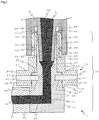
- FIG. 2 is a sectional view of the attachment/detachment mechanism 1 according to the present invention.
- the attachment/detachment mechanism 1 is mainly constituted by a support member 20 that is connected to the coupling member 15, and a rotation member 40 that is rotatably fitted over the support member 20.
- the support member 20 is in the form of an integral metal-made member, a lower portion of the support member 20 is called a base portion 21, a middle portion positioned above the base portion 21 is called a support portion 22, and an upper portion is called an insertion portion 23.
- the base portion 21 has an L-shaped channel (24, 25) formed therein to establish communication between the syringe 6 and the coupling member 15, and it is connected to the coupling member 15.
- the support portion 22 is disposed above the base portion 21, and a shoulder 28 of the support portion 22 supports the rotation member 40.
- the insertion portion 23 is disposed above the support portion 22, and it has an upper insertion hole 26 into which the inner cylindrical portion 62 of the syringe 6 is inserted.
- the L-shaped channel inside the base portion 21 is constituted by a connection-side channel 24 in communication with a channel 16 in the coupling member, and an inlet-side channel 25 in communication with the upper insertion hole 26.
- a mortar-shaped (inverted truncated conical) portion 27 is provided between the inlet-side channel 25 and the upper insertion hole 26.
- the connection-side channel 24 and the inlet-side channel 25 are communicated with each other in an orthogonal relation through a bent portion.
- the mortar-shaped portion 27 is provided to gradually and smoothly reduce a channel diameter from the upper insertion hole 26 toward the inlet-side channel 25.
- the mortar-shaped portion 27 may be omitted.
- the attachment parts of commercially available syringes have various shapes, it is also possible to prepare the plurality of base portions 21 having the upper insertion holes 26 in shapes adapted for a variety of attachment parts of the syringes, and to optionally use the prepared base portions 21 in combination with one or plural types of the rotation members 40.
- the upper insertion hole 26 extending in the vertical direction defines a channel tapered downward, namely gradually spreading upward, such that an inner peripheral surface 32 of the upper insertion hole comes into a close contact with an outer peripheral surface 67 of the inner cylindrical portion of the syringe 6 substantially over the entirety of both the surfaces.
- the inner peripheral surface 32 of the upper insertion hole has substantially the same taper gradient as that of the outer peripheral surface 67 of the inner cylindrical portion of the syringe 6.
- the liquid material 70 denoted by a region filled with a gray color in Fig. 2 , is supplied from the outlet channel 66 of the syringe 6 toward the channel 16 in the coupling member in a direction of an arrow (denoted by a numeral 71).
- the support portion 22 and the insertion portion 23 are in the form of continuous concentric columns, and the support portion 22 has a larger diameter than the insertion portion 23. Therefore, the shoulder 28 is formed at a connection boundary between the support portion 22 and the insertion portion 23.
- the rotation member 40 having through-holes (specifically, a through-hole 44 and a recess 45) is fitted over the support portion 22 and the insertion portion 23, and the fitted rotation member 40 is rotatably supported by the shoulder 28 of the support portion 22, the shoulder 28 having a relatively large diameter.
- the support portion 22 and the insertion portion 23 function like a shaft with respect to the rotation member 40.
- An annular groove 33 is circumferentially formed to be recessed in a lateral surface 29 of the support portion 22.
- a slip-off preventive member 51 described later is fitted into the annular groove 33.
- the rotation member 40 made of metal or resin includes an operating portion 41 positioned on the lower side, a barrel portion 42 positioned at a middle, and a prominent portion 43 positioned on the upper side.
- the barrel portion 42 and the prominent portion 43 are collectively called a raised portion in some cases.
- the operating portion 41 is a disk-shaped member.
- the recess 45 which connects to the through-hole 44 is formed in a central region of a bottom surface 48 of the operating portion 41.
- the barrel portion 42 is a disk-shaped member having a smaller diameter than the operating portion 41, and the through-hole 44 is formed at the center of the barrel portion 42.
- Positioning of the rotation member 40 is made by fitting the rotation member 40 over the insertion portion 23 of the support member 20, starting from the bottom surface side of the recess 45, and by engaging the recess 45 with the support portion 22.
- the through-holes (44 and 45) closely engaging with the support portion 22 and the insertion portion 23, which jointly form a stepped cylindrical column, are formed in the rotation member 40 in a concentric relation to a center axis of the rotation member 40.
- the shoulder 28 is preferably formed at such a height as allowing a slight gap to be defined between the bottom surface 48 of the rotation member and an upper surface 30 of the base portion, and as not impeding the rotation of the rotation member 40.
- a lateral insertion hole 47 penetrating through the operating portion 41 to be communicated with the recess 45 is formed to extend from a lateral surface 50 of the operating portion 41.
- the lateral insertion hole 47 is formed at the same height as the annular groove 33 of the support member 20.
- the lateral insertion hole 47 of the operating portion 41 is preferably formed to have thread grooves or a fitting member, which is engageable with the slip-off preventive member 51, in order to make the slip-off preventive member 51 tightly fixed. While, in the illustrated embodiment, pairs of the lateral insertion holes 47 and the slip-off preventive members 51 are disposed at two locations opposite to each other with a rotation axis interposed therebetween, the present invention is not limited to such an example. The pairs of the lateral insertion holes 47 and the slip-off preventive members 51 may be disposed, for example, at three locations (in a Y-shape when viewed from above) or four locations (in a cross shape when viewed from above) at equal intervals.
- the shape of the operating portion 41 is also not limited to a circle when viewed from above.
- the operating portion 41 may have, for example, an I-shape when viewed from above (in the case where the lateral insertion holes 47 are formed at two opposite locations), a Y-shape when viewed from above (in the case where the lateral insertion holes 47 are formed at three locations), or a cross shape when viewed from above (in the case where the lateral insertion holes 47 are formed at four locations).
- the lateral surface 50 of the operating portion is preferably given with anti-slip properties for the purpose of facilitating the operation.
- the lateral surface 50 may be treated with, e.g., knurling, pear-skin finishing, or sand blasting.
- a shape of the barrel portion 42 is also not limited to a circle when viewed from above.
- the barrel portion 42 may have the same diameter as the prominent portion 43 (namely, the prominent portion 43 may be directly raised from the operating portion 41 without providing the barrel portion 42).
- a screw portion 46 is formed in an outer peripheral surface of the prominent portion 43 and is engaged with the screw portion 65 formed in the inner surface of the attachment part 10 of the syringe 6.
- the screw portions (65 and 46) are each preferably in the form of a double thread screw or a luer connector.
- An upper end surface 49 of the rotation member and an upper end surface 31 of the support member are not always required to be positioned on the same plane. However, both the upper end surfaces 49 and 31 are preferably positioned on the same plane from the viewpoint of providing a guide to check whether the rotation member 40 is fitted up to a proper position.
- the operating portion 41, the barrel portion 42, and the prominent portion 43 may be formed integrally, or they may be constituted by combining a plurality of members with each other.
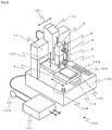
- the discharge device 2 is mounted to a desktop type application apparatus 100, and is used in an operation of applying the liquid material onto a workpiece 106 while the discharge device 2 and a worktable 103 are moved relatively to each other by XYZ-axis drive devices (111, 112 and 113).
- a numeral 111 denotes an X-axis drive device for the relative movement in an X-direction (denoted by a numeral 121)
- a numeral 112 denotes a Y-axis drive device for the relative movement in a Y-direction (denoted by a numeral 122)
- a numeral 113 denotes a Z-axis drive device for the relative movement in a Z-direction (denoted by a numeral 123).
- a servo motor, a combination of a stepping motor and a ball screw, a linear motor, or the like can be used as each of the XYZ-axis drive devices (111, 112 and 113).
- the above-mentioned drive devices are disposed on a base 105 in which an application control unit (not illustrated) for controlling operations of XYZ-axis drive devices is incorporated.
- Manual operation buttons 104 are disposed on an upper surface of the base 105.
- a dispense controller 101 is installed aside of the base 105, and compressed gas from a compressed gas source 102 is supplied to the syringe 6 under the desired conditions.
- the application apparatus 100 may include the plurality of discharge devices 2. Even when the plurality of discharge devices 2 are arranged in a state where the respective coupling members 15 are positioned parallel to each other, the attachment/detachment mechanism 1 according to the present invention can avoid the upper connection part 7 of one discharge device from contacting the upper connection part 7 of another adjacent discharge device. Therefore, an installation space for the plurality of discharge devices 2 can be minimized.
- the attachment/detachment mechanism 1 according to the present invention is particularly advantageous when used in a desktop type application apparatus for which space-saving is demanded strongly. However, it is a matter of course that the attachment/detachment mechanism 1 according to the present invention is applicable to a non-desktop type application apparatus as well.
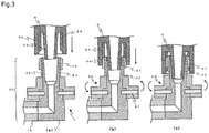
- FIG. 3 is an explanatory view referenced to explain the operation of the attachment/detachment mechanism 1 according to the present invention when the syringe 6 is attached.
- the syringe 6 may be detached through operation procedures that are reversed to the above-described ones. Also in the case of detaching the syringe 6, the syringe 6 can be moved (upward in the case of the detachment) just by rotating the rotation member 40 without rotating the syringe 6.
- the syringe can be attached and detached just by rotating the rotation member without rotating the syringe, it is possible to prevent not only twisting of a tube connected to the syringe, but also damage of the syringe itself.
- an overall width of the discharge device can be held relatively small by adjusting the orientations of the upper connection part and the adapter.
- attachment/detachment mechanism 2: discharge device (dispenser), 3: pump section, 4: pump drive section, 5: nozzle, 6: reservoir (syringe), 7: upper connection part, 8: adapter, 9: compressed gas supply tube, 10: attachment part, 15: coupling member, 16: channel in coupling member, 17: fixing member, 20: support member, 21: base, 22: support portion, 23: insertion portion, 24: connection-side channel, 25: inlet-side channel, 26: upper insertion hole, 27: mortar-shaped portion, 28: shoulder (upper surface of support portion), 29: lateral surface of support portion, 30: upper surface of base, 31: upper end surface of support member, 32: inner peripheral surface of insertion hole, 33: annular groove, 40: rotation member, 41: operating portion, 42: barrel portion, 43: prominent portion, 44: through-hole, 45: recess, 46: screw portion of the rotation member, 47: lateral insertion hole, 48: bottom surface (of rotation member), 49: upper end surface of rotation member, 50
Landscapes
- Engineering & Computer Science (AREA)
- General Engineering & Computer Science (AREA)
- Mechanical Engineering (AREA)
- Coating Apparatus (AREA)
- Quick-Acting Or Multi-Walled Pipe Joints (AREA)
Priority Applications (1)
| Application Number | Priority Date | Filing Date | Title |
|---|---|---|---|
| PL15826303T PL3175928T3 (pl) | 2014-07-30 | 2015-07-17 | Mocujący/odłączający strzykawkę mechanizm oraz urządzenie zaopatrzone w mechanizm |
Applications Claiming Priority (2)
| Application Number | Priority Date | Filing Date | Title |
|---|---|---|---|
| JP2014154387A JP6358885B2 (ja) | 2014-07-30 | 2014-07-30 | シリンジ着脱機構および当該機構を備える装置 |
| PCT/JP2015/070504 WO2016017453A1 (ja) | 2014-07-30 | 2015-07-17 | シリンジ着脱機構および当該機構を備える装置 |
Publications (3)
| Publication Number | Publication Date |
|---|---|
| EP3175928A1 EP3175928A1 (en) | 2017-06-07 |
| EP3175928A4 EP3175928A4 (en) | 2018-05-16 |
| EP3175928B1 true EP3175928B1 (en) | 2020-01-01 |
Family
ID=55217357
Family Applications (1)
| Application Number | Title | Priority Date | Filing Date |
|---|---|---|---|
| EP15826303.8A Active EP3175928B1 (en) | 2014-07-30 | 2015-07-17 | Syringe attachment/detachment mechanism and device provided with mechanism |
Country Status (13)
| Country | Link |
|---|---|
| US (1) | US10441967B2 (enExample) |
| EP (1) | EP3175928B1 (enExample) |
| JP (1) | JP6358885B2 (enExample) |
| KR (1) | KR102306481B1 (enExample) |
| CN (1) | CN106573269B (enExample) |
| ES (1) | ES2774088T3 (enExample) |
| HU (1) | HUE048678T2 (enExample) |
| MY (1) | MY182987A (enExample) |
| PL (1) | PL3175928T3 (enExample) |
| PT (1) | PT3175928T (enExample) |
| SG (1) | SG11201700494VA (enExample) |
| TW (1) | TWI667074B (enExample) |
| WO (1) | WO2016017453A1 (enExample) |
Cited By (1)
| Publication number | Priority date | Publication date | Assignee | Title |
|---|---|---|---|---|
| US11684725B2 (en) | 2018-12-19 | 2023-06-27 | Fenwal, Inc. | Disposable syringe for use with pneumatic drivers |
Families Citing this family (17)
| Publication number | Priority date | Publication date | Assignee | Title |
|---|---|---|---|---|
| JP6452147B2 (ja) * | 2015-01-19 | 2019-01-16 | 武蔵エンジニアリング株式会社 | 液体材料吐出装置 |
| JP6778426B2 (ja) * | 2016-09-20 | 2020-11-04 | 武蔵エンジニアリング株式会社 | 液体材料吐出装置 |
| KR102341945B1 (ko) * | 2017-03-13 | 2021-12-22 | 주식회사 탑 엔지니어링 | 기판 처리 장치 |
| MY200658A (en) | 2017-05-25 | 2024-01-09 | Musashi Eng Inc | Liquid material application apparatus and liquid material application method |
| KR102049000B1 (ko) * | 2017-07-19 | 2019-11-26 | 안동대학교 산학협력단 | 3차원 인공지지체 제조 장치 |
| KR101974747B1 (ko) * | 2017-10-24 | 2019-05-02 | (주)제이월드텍 | 진공믹서기 |
| KR102019591B1 (ko) * | 2018-02-08 | 2019-09-06 | 문병휘 | 시린지의 코트부재 및 이를 이용한 시린지의 재사용방법 |
| JP6471258B2 (ja) * | 2018-06-04 | 2019-02-13 | 武蔵エンジニアリング株式会社 | 液体材料塗布装置および液体材料塗布方法 |
| JP7093285B2 (ja) * | 2018-10-11 | 2022-06-29 | 株式会社Subaru | シール剤吐出装置 |
| JP7037734B2 (ja) * | 2019-09-05 | 2022-03-17 | 日立金属株式会社 | 熱電変換モジュールの製造方法 |
| JP7489092B2 (ja) * | 2020-04-10 | 2024-05-23 | 兵神装備株式会社 | 液剤塗布装置 |
| JP7282060B2 (ja) * | 2020-04-17 | 2023-05-26 | 孝志 上市 | メッキ装置 |
| CN112318099A (zh) * | 2020-10-23 | 2021-02-05 | 胡仓铜 | 一种汽车防尘总成件的装配设备 |
| WO2022216121A1 (ko) * | 2021-04-09 | 2022-10-13 | 엘지전자 주식회사 | 디스펜서 및 그를 갖는 잉크 도포 장비 |
| USD1045074S1 (en) * | 2021-08-20 | 2024-10-01 | Musashi Engineering, Inc. | Tube adapter for liquid precision discharge machine |
| JP2024100053A (ja) * | 2023-01-13 | 2024-07-26 | ブラザー工業株式会社 | 液体供給装置 |
| EP4579077A1 (en) * | 2023-12-27 | 2025-07-02 | Fenwal, Inc. | Fluid processing system with high pressure pneumatic syringe pump |
Family Cites Families (18)
| Publication number | Priority date | Publication date | Assignee | Title |
|---|---|---|---|---|
| JPS53107327U (enExample) * | 1977-02-04 | 1978-08-29 | ||
| US5010841A (en) | 1989-05-23 | 1991-04-30 | Mcdonnell Douglas Corporation | Rotating sealant applicator |
| JPH09505876A (ja) * | 1994-09-15 | 1997-06-10 | エンヴァイロン・プロダクツ・インコーポレーテッド | パイプの継手組立体、システム及び方法 |
| CN1124661A (zh) * | 1994-12-13 | 1996-06-19 | 斋藤嘉邦 | 注射器及注射器的装配方法 |
| US6095572A (en) * | 1998-01-20 | 2000-08-01 | Optimize Technologies, Inc. | Quarter turn quick connect fitting |
| JP4252646B2 (ja) * | 1998-08-10 | 2009-04-08 | 京石産業株式会社 | 自己シール型一重管継手 |
| WO2001044707A1 (en) * | 1999-12-15 | 2001-06-21 | Oystertec Plc | Hydraulic connectors |
| JP3570422B2 (ja) | 2002-11-26 | 2004-09-29 | 日立化成工業株式会社 | ディスペンサー用注射筒及びペースト状接着剤 |
| EP2032467B1 (en) | 2006-06-13 | 2010-08-18 | Nordson Corporation | Liquid dispensing syringe |
| JP2008068245A (ja) | 2006-09-11 | 2008-03-27 | Minoru Nakamura | 補給方式 |
| JP2010022881A (ja) * | 2007-03-30 | 2010-02-04 | Musashi Eng Co Ltd | 液材吐出装置および液材吐出方法 |
| US9156054B2 (en) * | 2007-05-18 | 2015-10-13 | Musashi Engineering, Inc. | Method and apparatus for discharging liquid material |
| USD738495S1 (en) | 2013-08-23 | 2015-09-08 | Nordson Corporation | Piston for a liquid dispensing syringe |
| KR100961759B1 (ko) * | 2008-06-25 | 2010-06-07 | 주식회사 프로텍 | 레진도포장치 |
| CN103491925A (zh) * | 2011-02-13 | 2014-01-01 | 艾力克·严 | 液体输送系统 |
| JP2013055096A (ja) | 2011-09-01 | 2013-03-21 | Panasonic Corp | ペースト塗布装置 |
| JP2013052350A (ja) * | 2011-09-05 | 2013-03-21 | Shibaura Mechatronics Corp | ペースト吐出装置、ペースト塗布装置及びペースト塗布方法 |
| JP2013107034A (ja) * | 2011-11-21 | 2013-06-06 | Panasonic Corp | 液剤塗布装置及び液剤塗布装置における空気抜き方法 |
-
2014
- 2014-07-30 JP JP2014154387A patent/JP6358885B2/ja active Active
-
2015
- 2015-07-17 PT PT158263038T patent/PT3175928T/pt unknown
- 2015-07-17 KR KR1020177004938A patent/KR102306481B1/ko active Active
- 2015-07-17 HU HUE15826303A patent/HUE048678T2/hu unknown
- 2015-07-17 SG SG11201700494VA patent/SG11201700494VA/en unknown
- 2015-07-17 ES ES15826303T patent/ES2774088T3/es active Active
- 2015-07-17 MY MYPI2017700301A patent/MY182987A/en unknown
- 2015-07-17 PL PL15826303T patent/PL3175928T3/pl unknown
- 2015-07-17 WO PCT/JP2015/070504 patent/WO2016017453A1/ja not_active Ceased
- 2015-07-17 US US15/329,359 patent/US10441967B2/en active Active
- 2015-07-17 CN CN201580041299.8A patent/CN106573269B/zh active Active
- 2015-07-17 EP EP15826303.8A patent/EP3175928B1/en active Active
- 2015-07-29 TW TW104124529A patent/TWI667074B/zh active
Non-Patent Citations (1)
| Title |
|---|
| None * |
Cited By (2)
| Publication number | Priority date | Publication date | Assignee | Title |
|---|---|---|---|---|
| US11684725B2 (en) | 2018-12-19 | 2023-06-27 | Fenwal, Inc. | Disposable syringe for use with pneumatic drivers |
| US11904147B2 (en) | 2018-12-19 | 2024-02-20 | Fenwal, Inc. | Methods and systems for mating disposable syringes with pneumatic drivers without breaking sterility |
Also Published As
| Publication number | Publication date |
|---|---|
| SG11201700494VA (en) | 2017-03-30 |
| KR20170038006A (ko) | 2017-04-05 |
| KR102306481B1 (ko) | 2021-09-28 |
| TWI667074B (zh) | 2019-08-01 |
| MY182987A (en) | 2021-02-05 |
| WO2016017453A1 (ja) | 2016-02-04 |
| US20170225188A1 (en) | 2017-08-10 |
| CN106573269B (zh) | 2019-05-14 |
| EP3175928A4 (en) | 2018-05-16 |
| US10441967B2 (en) | 2019-10-15 |
| HUE048678T2 (hu) | 2020-08-28 |
| PT3175928T (pt) | 2020-01-28 |
| ES2774088T3 (es) | 2020-07-16 |
| TW201607622A (zh) | 2016-03-01 |
| JP2016030242A (ja) | 2016-03-07 |
| CN106573269A (zh) | 2017-04-19 |
| EP3175928A1 (en) | 2017-06-07 |
| PL3175928T3 (pl) | 2020-06-29 |
| JP6358885B2 (ja) | 2018-07-18 |
Similar Documents
| Publication | Publication Date | Title |
|---|---|---|
| EP3175928B1 (en) | Syringe attachment/detachment mechanism and device provided with mechanism | |
| CN103786964B (zh) | 用于分配含均匀分布合成材料的流体的流体分配器和方法 | |
| CN104159676B (zh) | 液体定量吐出装置、其涂布装置及液体定量吐出方法 | |
| CN104918712B (zh) | 液态物的排出装置 | |
| KR101395126B1 (ko) | 액체 재료 토출 장치 | |
| KR102389654B1 (ko) | 액체 재료 토출 장치 | |
| US10086399B2 (en) | Device for administering a fluid product | |
| CN102247943A (zh) | 点胶装置 | |
| EP3769855A1 (en) | Liquid material ejecting apparatus | |
| CN107198804A (zh) | 一种针头装卸辅助装置 | |
| EP3590609B1 (en) | Device and method for supplying viscous material | |
| CN216500465U (zh) | 一种用于点酶机的保护套、针座组件和点酶机 | |
| HK1234700A1 (en) | Syringe attachment/detachment mechanism and device provided with mechanism | |
| CN111852818A (zh) | 一种压缩空气适配器、配量系统及其供料方法 | |
| KR20210015310A (ko) | 액체 토출장치 | |
| KR101477070B1 (ko) | 점성 액체 재료의 토출 방법 및 장치 | |
| HK1238603A1 (en) | Liquid material discharge apparatus | |
| HK1133229B (en) | Liquid material delivery apparatus | |
| HK1200401B (en) | Liquid dispensing apparatus, coating apparatus for same, and liquid dispensing method |
Legal Events
| Date | Code | Title | Description |
|---|---|---|---|
| STAA | Information on the status of an ep patent application or granted ep patent |
Free format text: STATUS: THE INTERNATIONAL PUBLICATION HAS BEEN MADE |
|
| 17P | Request for examination filed |
Effective date: 20170202 |
|
| AK | Designated contracting states |
Kind code of ref document: A1 Designated state(s): AL AT BE BG CH CY CZ DE DK EE ES FI FR GB GR HR HU IE IS IT LI LT LU LV MC MK MT NL NO PL PT RO RS SE SI SK SM TR |
|
| AX | Request for extension of the european patent |
Extension state: BA ME |
|
| PUAI | Public reference made under article 153(3) epc to a published international application that has entered the european phase |
Free format text: ORIGINAL CODE: 0009012 |
|
| STAA | Information on the status of an ep patent application or granted ep patent |
Free format text: STATUS: REQUEST FOR EXAMINATION WAS MADE |
|
| DAV | Request for validation of the european patent (deleted) | ||
| DAX | Request for extension of the european patent (deleted) | ||
| A4 | Supplementary search report drawn up and despatched |
Effective date: 20180412 |
|
| RIC1 | Information provided on ipc code assigned before grant |
Ipc: F16L 37/24 20060101ALI20180406BHEP Ipc: F16L 19/04 20060101ALN20180406BHEP Ipc: B05C 5/02 20060101ALI20180406BHEP Ipc: B05C 5/00 20060101ALI20180406BHEP Ipc: B05C 11/00 20060101AFI20180406BHEP |
|
| GRAP | Despatch of communication of intention to grant a patent |
Free format text: ORIGINAL CODE: EPIDOSNIGR1 |
|
| STAA | Information on the status of an ep patent application or granted ep patent |
Free format text: STATUS: GRANT OF PATENT IS INTENDED |
|
| RIC1 | Information provided on ipc code assigned before grant |
Ipc: B05C 11/00 20060101AFI20190619BHEP Ipc: F16L 37/24 20060101ALI20190619BHEP Ipc: B05C 5/00 20060101ALI20190619BHEP Ipc: B05C 5/02 20060101ALI20190619BHEP Ipc: F16L 19/04 20060101ALN20190619BHEP |
|
| INTG | Intention to grant announced |
Effective date: 20190716 |
|
| GRAS | Grant fee paid |
Free format text: ORIGINAL CODE: EPIDOSNIGR3 |
|
| GRAA | (expected) grant |
Free format text: ORIGINAL CODE: 0009210 |
|
| STAA | Information on the status of an ep patent application or granted ep patent |
Free format text: STATUS: THE PATENT HAS BEEN GRANTED |
|
| AK | Designated contracting states |
Kind code of ref document: B1 Designated state(s): AL AT BE BG CH CY CZ DE DK EE ES FI FR GB GR HR HU IE IS IT LI LT LU LV MC MK MT NL NO PL PT RO RS SE SI SK SM TR |
|
| REG | Reference to a national code |
Ref country code: GB Ref legal event code: FG4D |
|
| REG | Reference to a national code |
Ref country code: CH Ref legal event code: EP Ref country code: AT Ref legal event code: REF Ref document number: 1219115 Country of ref document: AT Kind code of ref document: T Effective date: 20200115 |
|
| REG | Reference to a national code |
Ref country code: DE Ref legal event code: R096 Ref document number: 602015044846 Country of ref document: DE |
|
| REG | Reference to a national code |
Ref country code: IE Ref legal event code: FG4D |
|
| REG | Reference to a national code |
Ref country code: PT Ref legal event code: SC4A Ref document number: 3175928 Country of ref document: PT Date of ref document: 20200128 Kind code of ref document: T Free format text: AVAILABILITY OF NATIONAL TRANSLATION Effective date: 20200121 |
|
| REG | Reference to a national code |
Ref country code: NL Ref legal event code: MP Effective date: 20200101 |
|
| REG | Reference to a national code |
Ref country code: LT Ref legal event code: MG4D |
|
| REG | Reference to a national code |
Ref country code: ES Ref legal event code: FG2A Ref document number: 2774088 Country of ref document: ES Kind code of ref document: T3 Effective date: 20200716 |
|
| PG25 | Lapsed in a contracting state [announced via postgrant information from national office to epo] |
Ref country code: RS Free format text: LAPSE BECAUSE OF FAILURE TO SUBMIT A TRANSLATION OF THE DESCRIPTION OR TO PAY THE FEE WITHIN THE PRESCRIBED TIME-LIMIT Effective date: 20200101 Ref country code: NL Free format text: LAPSE BECAUSE OF FAILURE TO SUBMIT A TRANSLATION OF THE DESCRIPTION OR TO PAY THE FEE WITHIN THE PRESCRIBED TIME-LIMIT Effective date: 20200101 Ref country code: LT Free format text: LAPSE BECAUSE OF FAILURE TO SUBMIT A TRANSLATION OF THE DESCRIPTION OR TO PAY THE FEE WITHIN THE PRESCRIBED TIME-LIMIT Effective date: 20200101 Ref country code: NO Free format text: LAPSE BECAUSE OF FAILURE TO SUBMIT A TRANSLATION OF THE DESCRIPTION OR TO PAY THE FEE WITHIN THE PRESCRIBED TIME-LIMIT Effective date: 20200401 Ref country code: FI Free format text: LAPSE BECAUSE OF FAILURE TO SUBMIT A TRANSLATION OF THE DESCRIPTION OR TO PAY THE FEE WITHIN THE PRESCRIBED TIME-LIMIT Effective date: 20200101 |
|
| REG | Reference to a national code |
Ref country code: HU Ref legal event code: AG4A Ref document number: E048678 Country of ref document: HU |
|
| PG25 | Lapsed in a contracting state [announced via postgrant information from national office to epo] |
Ref country code: LV Free format text: LAPSE BECAUSE OF FAILURE TO SUBMIT A TRANSLATION OF THE DESCRIPTION OR TO PAY THE FEE WITHIN THE PRESCRIBED TIME-LIMIT Effective date: 20200101 Ref country code: SE Free format text: LAPSE BECAUSE OF FAILURE TO SUBMIT A TRANSLATION OF THE DESCRIPTION OR TO PAY THE FEE WITHIN THE PRESCRIBED TIME-LIMIT Effective date: 20200101 Ref country code: HR Free format text: LAPSE BECAUSE OF FAILURE TO SUBMIT A TRANSLATION OF THE DESCRIPTION OR TO PAY THE FEE WITHIN THE PRESCRIBED TIME-LIMIT Effective date: 20200101 Ref country code: IS Free format text: LAPSE BECAUSE OF FAILURE TO SUBMIT A TRANSLATION OF THE DESCRIPTION OR TO PAY THE FEE WITHIN THE PRESCRIBED TIME-LIMIT Effective date: 20200501 Ref country code: GR Free format text: LAPSE BECAUSE OF FAILURE TO SUBMIT A TRANSLATION OF THE DESCRIPTION OR TO PAY THE FEE WITHIN THE PRESCRIBED TIME-LIMIT Effective date: 20200402 Ref country code: BG Free format text: LAPSE BECAUSE OF FAILURE TO SUBMIT A TRANSLATION OF THE DESCRIPTION OR TO PAY THE FEE WITHIN THE PRESCRIBED TIME-LIMIT Effective date: 20200401 |
|
| REG | Reference to a national code |
Ref country code: DE Ref legal event code: R097 Ref document number: 602015044846 Country of ref document: DE |
|
| PG25 | Lapsed in a contracting state [announced via postgrant information from national office to epo] |
Ref country code: SK Free format text: LAPSE BECAUSE OF FAILURE TO SUBMIT A TRANSLATION OF THE DESCRIPTION OR TO PAY THE FEE WITHIN THE PRESCRIBED TIME-LIMIT Effective date: 20200101 Ref country code: RO Free format text: LAPSE BECAUSE OF FAILURE TO SUBMIT A TRANSLATION OF THE DESCRIPTION OR TO PAY THE FEE WITHIN THE PRESCRIBED TIME-LIMIT Effective date: 20200101 Ref country code: EE Free format text: LAPSE BECAUSE OF FAILURE TO SUBMIT A TRANSLATION OF THE DESCRIPTION OR TO PAY THE FEE WITHIN THE PRESCRIBED TIME-LIMIT Effective date: 20200101 Ref country code: DK Free format text: LAPSE BECAUSE OF FAILURE TO SUBMIT A TRANSLATION OF THE DESCRIPTION OR TO PAY THE FEE WITHIN THE PRESCRIBED TIME-LIMIT Effective date: 20200101 Ref country code: SM Free format text: LAPSE BECAUSE OF FAILURE TO SUBMIT A TRANSLATION OF THE DESCRIPTION OR TO PAY THE FEE WITHIN THE PRESCRIBED TIME-LIMIT Effective date: 20200101 |
|
| PLBE | No opposition filed within time limit |
Free format text: ORIGINAL CODE: 0009261 |
|
| STAA | Information on the status of an ep patent application or granted ep patent |
Free format text: STATUS: NO OPPOSITION FILED WITHIN TIME LIMIT |
|
| REG | Reference to a national code |
Ref country code: AT Ref legal event code: MK05 Ref document number: 1219115 Country of ref document: AT Kind code of ref document: T Effective date: 20200101 |
|
| 26N | No opposition filed |
Effective date: 20201002 |
|
| PG25 | Lapsed in a contracting state [announced via postgrant information from national office to epo] |
Ref country code: IT Free format text: LAPSE BECAUSE OF FAILURE TO SUBMIT A TRANSLATION OF THE DESCRIPTION OR TO PAY THE FEE WITHIN THE PRESCRIBED TIME-LIMIT Effective date: 20200101 Ref country code: AT Free format text: LAPSE BECAUSE OF FAILURE TO SUBMIT A TRANSLATION OF THE DESCRIPTION OR TO PAY THE FEE WITHIN THE PRESCRIBED TIME-LIMIT Effective date: 20200101 |
|
| PG25 | Lapsed in a contracting state [announced via postgrant information from national office to epo] |
Ref country code: MC Free format text: LAPSE BECAUSE OF FAILURE TO SUBMIT A TRANSLATION OF THE DESCRIPTION OR TO PAY THE FEE WITHIN THE PRESCRIBED TIME-LIMIT Effective date: 20200101 Ref country code: SI Free format text: LAPSE BECAUSE OF FAILURE TO SUBMIT A TRANSLATION OF THE DESCRIPTION OR TO PAY THE FEE WITHIN THE PRESCRIBED TIME-LIMIT Effective date: 20200101 |
|
| REG | Reference to a national code |
Ref country code: CH Ref legal event code: PL |
|
| GBPC | Gb: european patent ceased through non-payment of renewal fee |
Effective date: 20200717 |
|
| REG | Reference to a national code |
Ref country code: BE Ref legal event code: MM Effective date: 20200731 |
|
| PG25 | Lapsed in a contracting state [announced via postgrant information from national office to epo] |
Ref country code: CH Free format text: LAPSE BECAUSE OF NON-PAYMENT OF DUE FEES Effective date: 20200731 Ref country code: GB Free format text: LAPSE BECAUSE OF NON-PAYMENT OF DUE FEES Effective date: 20200717 Ref country code: LU Free format text: LAPSE BECAUSE OF NON-PAYMENT OF DUE FEES Effective date: 20200717 Ref country code: LI Free format text: LAPSE BECAUSE OF NON-PAYMENT OF DUE FEES Effective date: 20200731 |
|
| PG25 | Lapsed in a contracting state [announced via postgrant information from national office to epo] |
Ref country code: BE Free format text: LAPSE BECAUSE OF NON-PAYMENT OF DUE FEES Effective date: 20200731 |
|
| PG25 | Lapsed in a contracting state [announced via postgrant information from national office to epo] |
Ref country code: IE Free format text: LAPSE BECAUSE OF NON-PAYMENT OF DUE FEES Effective date: 20200717 |
|
| PG25 | Lapsed in a contracting state [announced via postgrant information from national office to epo] |
Ref country code: TR Free format text: LAPSE BECAUSE OF FAILURE TO SUBMIT A TRANSLATION OF THE DESCRIPTION OR TO PAY THE FEE WITHIN THE PRESCRIBED TIME-LIMIT Effective date: 20200101 Ref country code: MT Free format text: LAPSE BECAUSE OF FAILURE TO SUBMIT A TRANSLATION OF THE DESCRIPTION OR TO PAY THE FEE WITHIN THE PRESCRIBED TIME-LIMIT Effective date: 20200101 Ref country code: CY Free format text: LAPSE BECAUSE OF FAILURE TO SUBMIT A TRANSLATION OF THE DESCRIPTION OR TO PAY THE FEE WITHIN THE PRESCRIBED TIME-LIMIT Effective date: 20200101 |
|
| PG25 | Lapsed in a contracting state [announced via postgrant information from national office to epo] |
Ref country code: MK Free format text: LAPSE BECAUSE OF FAILURE TO SUBMIT A TRANSLATION OF THE DESCRIPTION OR TO PAY THE FEE WITHIN THE PRESCRIBED TIME-LIMIT Effective date: 20200101 Ref country code: AL Free format text: LAPSE BECAUSE OF FAILURE TO SUBMIT A TRANSLATION OF THE DESCRIPTION OR TO PAY THE FEE WITHIN THE PRESCRIBED TIME-LIMIT Effective date: 20200101 |
|
| P01 | Opt-out of the competence of the unified patent court (upc) registered |
Effective date: 20230519 |
|
| PGFP | Annual fee paid to national office [announced via postgrant information from national office to epo] |
Ref country code: HU Payment date: 20250723 Year of fee payment: 11 |
|
| PGFP | Annual fee paid to national office [announced via postgrant information from national office to epo] |
Ref country code: PT Payment date: 20250703 Year of fee payment: 11 Ref country code: ES Payment date: 20250826 Year of fee payment: 11 |
|
| PGFP | Annual fee paid to national office [announced via postgrant information from national office to epo] |
Ref country code: DE Payment date: 20250722 Year of fee payment: 11 |
|
| PGFP | Annual fee paid to national office [announced via postgrant information from national office to epo] |
Ref country code: PL Payment date: 20250703 Year of fee payment: 11 |
|
| PGFP | Annual fee paid to national office [announced via postgrant information from national office to epo] |
Ref country code: FR Payment date: 20250725 Year of fee payment: 11 |
|
| PGFP | Annual fee paid to national office [announced via postgrant information from national office to epo] |
Ref country code: CZ Payment date: 20250708 Year of fee payment: 11 |