WO2016006651A1 - 光学部材およびその製造方法 - Google Patents
光学部材およびその製造方法 Download PDFInfo
- Publication number
- WO2016006651A1 WO2016006651A1 PCT/JP2015/069750 JP2015069750W WO2016006651A1 WO 2016006651 A1 WO2016006651 A1 WO 2016006651A1 JP 2015069750 W JP2015069750 W JP 2015069750W WO 2016006651 A1 WO2016006651 A1 WO 2016006651A1
- Authority
- WO
- WIPO (PCT)
- Prior art keywords
- moth
- refractive index
- eye structure
- interface
- optical member
- Prior art date
Links
Images


Classifications
-
- G—PHYSICS
- G02—OPTICS
- G02B—OPTICAL ELEMENTS, SYSTEMS OR APPARATUS
- G02B1/00—Optical elements characterised by the material of which they are made; Optical coatings for optical elements
- G02B1/10—Optical coatings produced by application to, or surface treatment of, optical elements
- G02B1/11—Anti-reflection coatings
- G02B1/111—Anti-reflection coatings using layers comprising organic materials
-
- G—PHYSICS
- G02—OPTICS
- G02B—OPTICAL ELEMENTS, SYSTEMS OR APPARATUS
- G02B1/00—Optical elements characterised by the material of which they are made; Optical coatings for optical elements
- G02B1/10—Optical coatings produced by application to, or surface treatment of, optical elements
- G02B1/11—Anti-reflection coatings
- G02B1/118—Anti-reflection coatings having sub-optical wavelength surface structures designed to provide an enhanced transmittance, e.g. moth-eye structures
-
- G—PHYSICS
- G02—OPTICS
- G02B—OPTICAL ELEMENTS, SYSTEMS OR APPARATUS
- G02B1/00—Optical elements characterised by the material of which they are made; Optical coatings for optical elements
- G02B1/10—Optical coatings produced by application to, or surface treatment of, optical elements
- G02B1/11—Anti-reflection coatings
- G02B1/113—Anti-reflection coatings using inorganic layer materials only
- G02B1/115—Multilayers
Definitions
- the present invention relates to an optical member that suppresses reflection of light on the surface and a manufacturing method thereof.
- the conventional one does not have sufficient ability to suppress light reflection, and further improvement in performance is desired. Further, the conventional one only considers reflection when the incident angle of light is constant, and does not consider the case where the incident angle of light has a width. For example, reflection of light could be suppressed when the incident angle of light was close to 0 ° (vertical), but reflection could not be sufficiently suppressed as the incident angle increased. Therefore, when there is a curvature like a lens and there is a width in the incident angle of light, the reflection of light cannot be sufficiently suppressed.
- an object of the present invention is to provide an optical member that can further suppress reflection of light and a method for manufacturing the same. It is another object of the present invention to provide an optical member that can sufficiently suppress the reflection of light even when the incident angle of light has a width, and a manufacturing method thereof.
- the optical member of the present invention is composed of a base material and a moth-eye structure comprising predetermined irregularities, and the refractive index is between the base material and the moth-eye structure.
- One or more buffer layers made of a material lower than the refractive index of the base material and higher than the refractive index of the material of the moth-eye structure are formed.
- the position of the interface on the substrate side of the moth-eye structure is 0, the shortest distance from the interface to the moth-eye structure side is t, the refractive index of the buffer layer closest to the moth-eye structure is n B , and from the interface
- the average refractive index of the moth-eye structure at the position of the distance t is n t
- the shortest distance from the interface to the top of the convex part of the moth-eye structure is h
- the refractive index of the medium in contact with the surface of the moth-eye structure is n M
- Refractive index n t is the following formula (1) ... Formula (1) It is preferable that the average refractive index of the moth-eye structure is adjusted so as to satisfy the above.
- the position of the interface between the base material and the buffer layer is 0, the shortest distance from the interface to the moth-eye structure side is t, the refractive index of the base material is n S , and the buffer layer is at a distance t from the interface the average refractive index of the refractive index or moth-eye structure n t of the shortest distance to the protrusion apex of the interface and the moth-eye structure h, the refractive index of the medium in contact with the surface of the moth-eye structure and n M, refractive index n t Is the following formula (2) ... Formula (2) It is preferable to adjust the refractive index of the buffer layer and the average refractive index of the moth-eye structure so as to satisfy the above.
- the moth-eye structure is preferably a cone shape or a frustum shape.
- the optical member manufacturing method of the present invention is a method for manufacturing an optical member comprising a base material, a moth-eye structure composed of predetermined irregularities, and one or more buffer layers formed between the base material and the moth-eye structure.
- the method is characterized in that a material having a refractive index lower than that of the base material and higher than that of the material of the moth-eye structure is used as the material of the buffer layer.
- the position of the interface on the substrate side of the moth-eye structure is 0, the shortest distance from the interface to the moth-eye structure side is t, the refractive index of the buffer layer closest to the moth-eye structure is n B , and from the interface
- the average refractive index of the moth-eye structure at the position of the distance t is n t
- the shortest distance from the interface to the top of the convex part of the moth-eye structure is h
- the refractive index of the medium in contact with the surface of the moth-eye structure is n M
- Refractive index n t is the following formula (1) ... Formula (1) It is preferable to adjust the refractive index of the buffer layer and the average refractive index of the moth-eye structure so as to satisfy the above.
- the position of the interface between the base material and the buffer layer is 0, the shortest distance from the interface to the moth-eye structure side is t, the refractive index of the base material is n S , and the buffer layer is at a distance t from the interface the average refractive index of the refractive index or moth-eye structure n t of the shortest distance to the protrusion apex of the interface and the moth-eye structure h, the refractive index of the medium in contact with the surface of the moth-eye structure and n M, refractive index n t Is the following formula (2) ... Formula (2) It is preferable to adjust the refractive index of the buffer layer and the average refractive index of the moth-eye structure so as to satisfy
- the moth-eye structure has a cone shape or a frustum shape.
- the optical member of the present invention can provide an optical member that can sufficiently suppress the reflection of light even when the incident angle of light has a width by controlling the change in refractive index.
- the optical member of the present invention comprises a base material 1, a moth-eye structure 3 composed of predetermined irregularities, and one or more buffer layers 2 formed between the base material 1 and the moth-eye structure 3, The refractive index change between the material 1 and the medium is adjusted by the buffer layer 2 and the moth-eye structure 3.
- the optical member means a member having a surface that transmits light, and examples thereof include a lens, a prism, a filter, a mirror, and a display.
- the substrate 1 has a predetermined function as an optical member.
- the shape is not particularly limited, and can be freely designed according to the function and application of the optical member, such as a plate shape like a display or a curved shape like a lens.
- the material can be freely selected according to the function and application of the optical member.
- a material that is optically transparent in the visible light region of 400 nm to 780 nm is preferable because it can be used for various optical applications.
- When used in the ultraviolet region it is preferable to use a material containing quartz glass or sapphire glass having a high ultraviolet transmittance.
- the medium means a substance / object that is a field through which light propagates, and means a gas such as air or a liquid such as water in contact with the surface of the optical member (the surface of the moth-eye structure 3). May be.
- the moth-eye structure 3 is a fine concavo-convex structure that resembles the shape of a “brown eye”. Light is likely to be reflected at portions where the refractive index changes greatly. On the other hand, if the irregularities of the moth-eye structure 3 are formed with a period smaller than the wavelength of the visible light region, the light has the refractive index of the medium at any position in the height direction of the irregularities and the refractive index of the material used for the moth-eye structure 3. It is known that the average average refractive index behaves as if it were the refractive index at that position.
- the concave-convex structure includes a cone shape such as a cone, a frustum shape that is a three-dimensional figure obtained by removing a cone that has been reduced to a similar size and sharing a vertex with the cone, or the side surfaces of the cone are expanded outward.
- a shell shape or the like is used. Of course, it is not restricted to these.
- any conventionally known method may be used, and a technique such as nanoimprint, injection molding, or photolithography may be used.
- the moth-eye structure 3 can suppress the reflection of light on the surface as the refractive index changes more gradually. Therefore, if the refractive index of the material used for the moth-eye structure 3 is the same, the longer the distance between the surface of the substrate 1 and the convex vertex of the moth-eye structure 3, the more light reflection can be suppressed. However, it is difficult to increase the distance only with the moth-eye structure 3 because of processing restrictions. Therefore, in the optical member of the present invention, as shown in FIG. 1, the refractive index between the base material 1 and the moth-eye structure 3 is lower than the refractive index of the base material 1 and higher than the refractive index of the material of the moth-eye structure 3.
- One or more buffer layers 2 made of a high material were formed. When two or more buffer layers 2 are formed, they are arranged so that the refractive index of the buffer layer 2 on the substrate 1 side is higher than the refractive index of the buffer layer 2 on the moth-eye structure 3 side.
- the reason for configuring in this way is that a material having a low refractive index can be used for the moth-eye structure 3, and a change in refractive index can be reduced.
- the material of the buffer layer 2 and the moth-eye structure 3 can be freely selected, for example, a material whose refractive index is adjusted by a siloxane material can be used.
- any method may be used as long as the base material 1 and the buffer layer 2 can be uniformly adhered.
- thermosetting with adjusted refractive index is possible.
- the material can be formed by spin coating and heating.
- optical characteristics show the optical characteristics with and without the buffer layer 2 between the base material 1 and the moth-eye structure 3.
- optical characteristics the relationship between the wavelength of light and the ratio of the intensity of reflected light to incident light (reflected light / incident light) was measured.
- the light was applied to the optical member at an incident angle of 0 ° (perpendicular to the optical member), and the relationship between the intensity of reflected light and the wavelength in the direction of the incident angle of 0 ° was measured.
- the wavelength was measured in the visible light range of 400 nm to 700 nm.
- the optical member includes a base material 1 made of glass (PCD51) having a refractive index of 1.59, a buffer layer 2 made of a siloxane material having a refractive index of 1.52, and a refractive index of 1.47.
- An optical member (Example 1) composed of a moth-eye structure 3 made of a siloxane material, a base material 1 made of glass having a refractive index of 1.59, and a siloxane material having a refractive index of 1.47 as shown in FIG.
- the moth-eye structure 3 a bullet-shaped concavo-convex shape having a height of 220 nm and a bottom diameter of 250 nm in a triangular arrangement with a pitch of 250 nm was used.
- the moth-eye structure was fabricated by nanoimprint technology.
- the thickness of the remaining film of the moth-eye structure 3 between the moth-eye structure 3 and the buffer layer 2 in Example 1 is 20 nm, and the thickness of the buffer layer 2 is 35 nm.
- the thickness of the remaining film of the moth-eye structure 3 lying between 1 and 160 was 160 nm.
- the experiment was performed in the atmosphere. That is, the medium is air having a refractive index of 1.000.
- the moth-eye structure 3 has 0 as the position of the interface on the substrate 1 side of the moth-eye structure 3, t as the shortest distance from the interface to the moth-eye structure 3 side, and the refraction of the substrate 1
- the refractive index is n S
- the average refractive index of the moth-eye structure 3 at a distance t from the interface is n t
- the shortest distance from the interface to the convex vertex of the moth-eye structure 3 is h
- the refractive index of the medium in contact with the surface of the moth-eye structure 3 Is n M
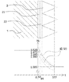
- the refractive index n t is an error of 15% or less of the difference (n S ⁇ n M ) between the refractive index n S of the substrate 1 and the refractive index n M of the medium. It was found that the effect of suppressing reflection of light from a wide range of angles was sufficiently high. This is expressed by the following formula (B). ... Formula (B) In the moth-eye structure 3, the uneven structure that satisfies the formula (A) is a cone such as a cone. FIG. 6 illustrates the relationship between the formulas (A) and (B) and the moth-eye structure 3 that satisfies the formula (A).
- FIG. 7 shows the result of simulating optical characteristics of an optical member (Example 2) that satisfies the formula (B), and FIG.
- the optical characteristics the relationship between the wavelength of light and the ratio of the intensity of reflected light to incident light (reflected light / incident light) was calculated.
- the light was irradiated onto the optical member at incident angles of 0 °, 15 °, 30 °, and 45 °, and the relationship between the intensity of reflected light and the wavelength in the direction of the incident angle of 0 ° was calculated.
- the wavelength was calculated for the visible light range of 400 nm to 700 nm.
- a software DiffractMOD manufactured by Synopsys, Inc. was used.
- the refractive index of the material used for the base material 1 and the moth-eye structure 3 as an optical member is 1.52.
- the moth-eye structure 3 of the optical member has a conical unevenness with a height of 450 nm and a diameter of 200 nm arranged in a triangular arrangement with a pitch of 200 nm (see FIG. 9), and a mean refractive index of 450 nm with a diameter of 200 nm and a linear average refractive index.
- the bullet-shaped irregularities changing in a triangular pattern with a pitch of 200 nm were used (see FIG. 10).
- the medium on the surface of the optical member was air having a refractive index of 1.00.
- the position of the interface (uneven bottom surface) on the base material 1 side of the moth-eye structure 3 is set to 0,
- the shortest distance from the interface to the moth-eye structure 3 side is t
- the refractive index of the buffer layer 2 closest to the moth-eye structure 3 is n B
- the average refractive index of the moth-eye structure 3 at the distance t from the interface is n t
- the moth-eye from the interface When the shortest distance to the top of the convex portion of the structure 3 is h and the refractive index of the medium in contact with the surface of the moth-eye structure 3 is n M , the refractive index n t is expressed by the following formula (1).
- Formula (1) It is preferable to adjust the average refractive index of the moth-eye structure 3 so as to satisfy the above.
- filled arbitrary shapes, such as cone shape other than a cone, frustum shape, and a shell shape, can be applied to the unevenness
- FIG. The error is preferably as small as 10% or less, 8% or less, 5% or less, 3% or less, 2% or less, or 1% or less.
- the thickness and refractive index of the buffer layer 2 are considered, but it is preferable to consider the thickness and refractive index of the buffer layer 2. That is, the position of the interface between the base material 1 and the buffer layer 2 is 0, the shortest distance from the interface to the moth-eye structure side is t, the refractive index of the base material 1 is n S , and the refraction of the buffer layer 2 at the position of the distance t from the interface.
- the refractive index n t is the following formula (2) ... Formula (2) It is more preferable to adjust the refractive index of the buffer layer 2 and the average refractive index of the moth-eye structure 3 so as to satisfy the above. Also in this case, the error is preferably as small as 10% or less, 8% or less, 5% or less, 3% or less, 2% or less, or 1% or less.
- FIG. 11 shows the result of simulating the optical characteristics of an optical member (Example 3) that satisfies the formula (2)
- FIG. 12 shows the optical characteristics of the optical member (Comparative Example 2) that does not satisfy the formula (2).
- the optical characteristics the relationship between the wavelength of light and the ratio of the intensity of reflected light to incident light (reflected light / incident light) was calculated. The light was irradiated onto the optical member at incident angles of 0 °, 15 °, 30 °, and 45 °, and the relationship between the intensity of reflected light and the wavelength in the direction of the incident angle of 0 ° was calculated. The wavelength was calculated for the visible light range of 400 nm to 700 nm. For the simulation, a software DiffractMOD manufactured by Synopsys, Inc. was used.
- the optical member has a refractive index of 1.52, the refractive index of the first buffer layer 21 is 1.473, the refractive index of the second buffer layer 22 is 1.385, and a moth-eye structure.
- the material used for 3 has a refractive index of 1.38 (Example 3) and, as shown in FIG. 14, there is no buffer layer, the refractive index of the substrate 1 is 1.52, and the refractive index of the material used for the moth-eye structure 3 With a value of 1.38 (Comparative Example 3).
- both the example 3 and the comparative example 3 remove the cone having a height of 73 nm and a diameter of 40 nm sharing a vertex from the cone having a height of 366 nm and a diameter of 200 nm.
- a truncated cone having a height of 293 nm and a triangular arrangement with a pitch of 200 nm was used.
- the film thicknesses of the first buffer layer 21 and the second buffer layer 22 were both 42 nm.
- the medium on the surface of the optical member was air having a refractive index of 1.
Abstract
Description

を満たすように前記モスアイ構造の平均屈折率を調節したものである方が好ましい。

を満たすように緩衝層の屈折率およびモスアイ構造の平均屈折率を調節したものである方が好ましい。

を満たすように緩衝層の屈折率およびモスアイ構造の平均屈折率を調節する方が好ましい。
・・・式(2)


なお、モスアイ構造3において、式(A)を満たすような凹凸構造は円錐等の錐体である。図6に、式(A)及び式(B)と、式(A)を満たすモスアイ構造3との関係を図示する。

を満たすようにモスアイ構造3の平均屈折率を調節する方が好ましい。なお、式(1)を満たす限り、モスアイ構造3の凹凸は円錐以外の錐体形状や錐台形状、砲弾形状等、任意の形状を適用することができる。また、誤差は10%以下、8%以下、5%以下、3%以下、2%以下、1%以下と、小さい方が好ましい。

を満たすように緩衝層2の屈折率およびモスアイ構造3の平均屈折率を調節する方がより好ましい。この場合にも、誤差は10%以下、8%以下、5%以下、3%以下、2%以下、1%以下と、小さい方が好ましい。
2 緩衝層
3 モスアイ構造
21 第1緩衝層
22 第2緩衝層
Claims (8)
- 基材と、所定の凹凸からなるモスアイ構造とからなる光学部材であって、
前記基材と前記モスアイ構造との間に、屈折率が前記基材の屈折率よりも低く前記モスアイ構造の材料の屈折率よりも高い材料からなる1以上の緩衝層が形成されていることを特徴とする光学部材。 - 前記モスアイ構造の基材側の界面の位置を0、前記界面から前記モスアイ構造側への最短距離をt、前記モスアイ構造に最も近い前記緩衝層の屈折率をnB、前記界面から距離tの位置における前記モスアイ構造の平均屈折率をnt、前記界面から前記モスアイ構造の凸部頂点までの最短距離をh、前記モスアイ構造の表面と接する媒質の屈折率をnMとすると、屈折率ntが下記式(1)
・・・式(1)
を満たすように前記モスアイ構造の平均屈折率を調節したものであることを特徴とする請求項1記載の光学部材。 - 前記基材と前記緩衝層の界面の位置を0、前記界面から前記モスアイ構造側への最短距離をt、前記基材の屈折率をnS、前記界面から距離tの位置における緩衝層の屈折率又はモスアイ構造の平均屈折率をnt、前記界面とモスアイ構造の凸部頂点までの最短距離をh、モスアイ構造の表面と接する媒質の屈折率をnMとすると、屈折率ntが下記式(2)
・・・式(2)
を満たすように緩衝層の屈折率およびモスアイ構造の平均屈折率を調節したものであることを特徴とする請求項1記載の光学部材。 - 前記モスアイ構造は、錐体形状又は錐台形状であることを特徴とする請求項1ないし3のいずれかに記載の光学部材。
- 基材と、所定の凹凸からなるモスアイ構造と、前記基材と前記モスアイ構造の間に形成される1以上の緩衝層と、からなる光学部材製造方法であって、
前記緩衝層の材料に、屈折率が前記基材の屈折率よりも低く前記モスアイ構造の材料の屈折率よりも高い材料を用いることを特徴とする光学部材製造方法。 - 前記モスアイ構造の基材側の界面の位置を0、前記界面から前記モスアイ構造側への最短距離をt、前記モスアイ構造に最も近い前記緩衝層の屈折率をnB、前記界面から距離tの位置における前記モスアイ構造の平均屈折率をnt、前記界面から前記モスアイ構造の凸部頂点までの最短距離をh、前記モスアイ構造の表面と接する媒質の屈折率をnMとすると、屈折率ntが下記式(1)
・・・式(1)
を満たすように緩衝層の屈折率およびモスアイ構造の平均屈折率を調節することを特徴とする請求項5記載の光学部材製造方法。 - 前記基材と前記緩衝層の界面の位置を0、前記界面から前記モスアイ構造側への最短距離をt、前記基材の屈折率をnS、前記界面から距離tの位置における緩衝層の屈折率又はモスアイ構造の平均屈折率をnt、前記界面とモスアイ構造の凸部頂点までの最短距離をh、モスアイ構造の表面と接する媒質の屈折率をnMとすると、屈折率ntが下記式(2)
・・・式(2)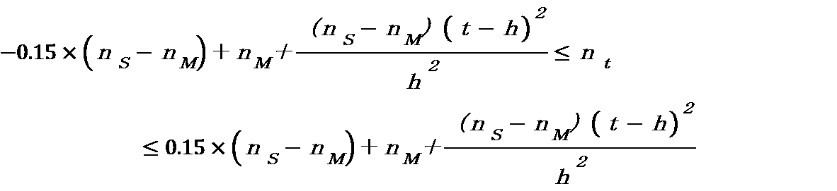
を満たすように緩衝層の屈折率およびモスアイ構造の平均屈折率を調節することを特徴とする請求項5記載の光学部材製造方法。 - 前記モスアイ構造を、錐体形状又は錐台形状にすることを特徴とする請求項5ないし7のいずれかに記載の光学部材製造方法。
Priority Applications (5)
| Application Number | Priority Date | Filing Date | Title |
|---|---|---|---|
| KR1020167032002A KR20170030473A (ko) | 2014-07-10 | 2015-07-09 | 광학 부재 및 그 제조 방법 |
| US14/889,914 US9851474B2 (en) | 2014-07-10 | 2015-07-09 | Optical component and method of producing the same |
| CN201580026483.5A CN106662673B (zh) | 2014-07-10 | 2015-07-09 | 光学部件及其制造方法 |
| JP2016532965A JPWO2016006651A1 (ja) | 2014-07-10 | 2015-07-09 | 光学部材およびその製造方法 |
| EP15785043.9A EP3168656B1 (en) | 2014-07-10 | 2015-07-09 | Optical element and method for producing same |
Applications Claiming Priority (2)
| Application Number | Priority Date | Filing Date | Title |
|---|---|---|---|
| JP2014141958 | 2014-07-10 | ||
| JP2014-141958 | 2014-07-10 |
Publications (1)
| Publication Number | Publication Date |
|---|---|
| WO2016006651A1 true WO2016006651A1 (ja) | 2016-01-14 |
Family
ID=55064279
Family Applications (1)
| Application Number | Title | Priority Date | Filing Date |
|---|---|---|---|
| PCT/JP2015/069750 WO2016006651A1 (ja) | 2014-07-10 | 2015-07-09 | 光学部材およびその製造方法 |
Country Status (6)
| Country | Link |
|---|---|
| US (1) | US9851474B2 (ja) |
| EP (1) | EP3168656B1 (ja) |
| JP (1) | JPWO2016006651A1 (ja) |
| KR (1) | KR20170030473A (ja) |
| CN (1) | CN106662673B (ja) |
| WO (1) | WO2016006651A1 (ja) |
Families Citing this family (3)
| Publication number | Priority date | Publication date | Assignee | Title |
|---|---|---|---|---|
| US20200309995A1 (en) * | 2019-03-26 | 2020-10-01 | Facebook Technologies, Llc | Anti-reflective coatings for transparent electroactive transducers |
| KR20220022303A (ko) | 2020-08-18 | 2022-02-25 | 삼성전기주식회사 | 카메라 모듈 및 휴대 단말기 |
| CN115598794A (zh) * | 2021-07-09 | 2023-01-13 | 大立光电股份有限公司(Tw) | 成像镜头与电子装置 |
Citations (3)
| Publication number | Priority date | Publication date | Assignee | Title |
|---|---|---|---|---|
| JP2010078803A (ja) * | 2008-09-25 | 2010-04-08 | Canon Inc | 光学素子及びそれを有する光学系 |
| JP2014051601A (ja) | 2012-09-07 | 2014-03-20 | Nippon Shokubai Co Ltd | 光学用成形体 |
| JP2014109635A (ja) * | 2012-11-30 | 2014-06-12 | Canon Inc | 光学用部材及びその製造方法 |
Family Cites Families (22)
| Publication number | Priority date | Publication date | Assignee | Title |
|---|---|---|---|---|
| EP1412782A4 (en) * | 2000-11-03 | 2006-02-15 | Mems Optical Inc | ANTI-REFLECTIVE STRUCTURES |
| JP4506070B2 (ja) * | 2002-11-01 | 2010-07-21 | コニカミノルタホールディングス株式会社 | 防眩層の形成方法、防眩フィルムの製造方法及び防眩層形成用のインクジェット装置 |
| JP2007264594A (ja) * | 2006-03-01 | 2007-10-11 | Nissan Motor Co Ltd | 反射防止微細構造、反射防止成形体及びその製造方法 |
| EP1921470A3 (en) * | 2006-11-08 | 2011-11-30 | Nissan Motor Co., Ltd. | Water Repellent Anti-Reflective Structure and Method of Manufacturing the Same |
| EP2031424B1 (en) * | 2007-08-28 | 2011-03-09 | Nissan Motor Co., Ltd. | Antireflective structure and antireflective moulded body |
| JP2009075539A (ja) * | 2007-08-28 | 2009-04-09 | Nissan Motor Co Ltd | 反射防止構造及び反射防止成形体 |
| JP5257066B2 (ja) * | 2008-12-26 | 2013-08-07 | ソニー株式会社 | 光学素子、表示装置、反射防止機能付き光学部品、および原盤 |
| JP2011053496A (ja) * | 2009-09-02 | 2011-03-17 | Sony Corp | 光学素子およびその製造方法、ならびに原盤の製造方法 |
| JP5511307B2 (ja) * | 2009-10-23 | 2014-06-04 | キヤノン株式会社 | 光学部材、及びその製造方法 |
| JP4991943B2 (ja) * | 2010-02-26 | 2012-08-08 | キヤノン株式会社 | 光学用部材、ポリイミド、およびその製造方法 |
| JP5773576B2 (ja) * | 2010-04-01 | 2015-09-02 | キヤノン株式会社 | 反射防止構造および光学機器 |
| JP2012189846A (ja) * | 2011-03-11 | 2012-10-04 | Tamron Co Ltd | 反射防止光学素子及び反射防止光学素子の製造方法 |
| EP2711742A4 (en) * | 2011-05-17 | 2014-10-29 | Canon Denshi Kk | OPTICAL FILTER, OPTICAL DEVICE, ELECTRONIC DEVICE AND ANTI-REFLECTION COMPLEX |
| CN103688195B (zh) * | 2011-05-17 | 2017-03-08 | 佳能电子株式会社 | 光学滤波器和光学设备 |
| JP5840448B2 (ja) * | 2011-10-12 | 2016-01-06 | 株式会社タムロン | 反射防止膜及び反射防止膜の製造方法 |
| EP2827177B1 (en) * | 2012-03-15 | 2017-11-29 | Soken Chemical & Engineering Co., Ltd. | Anti-reflection film |
| RU2604568C2 (ru) * | 2012-04-02 | 2016-12-10 | Асахи Касеи И-Матириалс Корпорейшн | Оптическая подложка, полупроводниковый светоизлучающий элемент и способ изготовления полупроводникового светоизлучающего элемента |
| JPWO2013172448A1 (ja) * | 2012-05-18 | 2016-01-12 | 三菱レイヨン株式会社 | フィルムとその製造方法、板状物、画像表示装置、太陽電池 |
| JP6189612B2 (ja) * | 2012-10-17 | 2017-08-30 | 富士フイルム株式会社 | 反射防止膜を備えた光学部材およびその製造方法 |
| US20150103396A1 (en) * | 2013-05-01 | 2015-04-16 | Byron Zollars | Antireflective Structures for Optics |
| JP2015068853A (ja) * | 2013-09-26 | 2015-04-13 | ソニー株式会社 | 積層体、撮像素子パッケージ、撮像装置および電子機器 |
| US9880328B2 (en) * | 2013-12-12 | 2018-01-30 | Corning Incorporated | Transparent diffusers for lightguides and luminaires |
-
2015
- 2015-07-09 EP EP15785043.9A patent/EP3168656B1/en not_active Not-in-force
- 2015-07-09 WO PCT/JP2015/069750 patent/WO2016006651A1/ja active Application Filing
- 2015-07-09 JP JP2016532965A patent/JPWO2016006651A1/ja active Pending
- 2015-07-09 CN CN201580026483.5A patent/CN106662673B/zh not_active Expired - Fee Related
- 2015-07-09 US US14/889,914 patent/US9851474B2/en active Active
- 2015-07-09 KR KR1020167032002A patent/KR20170030473A/ko unknown
Patent Citations (3)
| Publication number | Priority date | Publication date | Assignee | Title |
|---|---|---|---|---|
| JP2010078803A (ja) * | 2008-09-25 | 2010-04-08 | Canon Inc | 光学素子及びそれを有する光学系 |
| JP2014051601A (ja) | 2012-09-07 | 2014-03-20 | Nippon Shokubai Co Ltd | 光学用成形体 |
| JP2014109635A (ja) * | 2012-11-30 | 2014-06-12 | Canon Inc | 光学用部材及びその製造方法 |
Non-Patent Citations (1)
| Title |
|---|
| See also references of EP3168656A4 |
Also Published As
| Publication number | Publication date |
|---|---|
| EP3168656B1 (en) | 2019-04-17 |
| KR20170030473A (ko) | 2017-03-17 |
| JPWO2016006651A1 (ja) | 2017-04-27 |
| US9851474B2 (en) | 2017-12-26 |
| US20170108623A1 (en) | 2017-04-20 |
| CN106662673B (zh) | 2018-11-30 |
| EP3168656A4 (en) | 2018-03-21 |
| EP3168656A1 (en) | 2017-05-17 |
| CN106662673A (zh) | 2017-05-10 |
Similar Documents
| Publication | Publication Date | Title |
|---|---|---|
| JP6564376B2 (ja) | ライトガイドおよび照明器具用透明拡散器 | |
| JP5082097B2 (ja) | 反射防止構造および該反射防止構造を有する発光素子 | |
| CN105308482A (zh) | 具备防反射膜的光学部件 | |
| TW202041919A (zh) | 繞射光導板以及眼用佩戴品 | |
| WO2016006651A1 (ja) | 光学部材およびその製造方法 | |
| JP2009075539A (ja) | 反射防止構造及び反射防止成形体 | |
| WO2019024572A1 (zh) | 抗反射结构、显示装置及抗反射结构制作方法 | |
| JP2011107195A (ja) | 光学素子および光学素子の製造方法ならびに微細凹凸構造および成形型 | |
| CN110114698A (zh) | 反射型扩散板、显示装置、投影装置及照明装置 | |
| JP6642442B2 (ja) | 光学素子、光学複合素子及び保護フィルム付光学複合素子 | |
| Phillips et al. | Engineered Biomimicry: Chapter 12. Biomimetic Antireflection Surfaces | |
| JP5961906B2 (ja) | 超撥水基板及びその製造方法 | |
| JP2008209448A (ja) | 反射防止構造体 | |
| Leem et al. | Thermal-tolerant polymers with antireflective and hydrophobic grooved subwavelength grating surfaces for high-performance optics | |
| JP2003279706A (ja) | 反射防止部材 | |
| JP2010237419A (ja) | 反射防止体 | |
| JP2012208257A (ja) | 反射防止構造及び光学部材 | |
| JP6807177B2 (ja) | 反射型スクリーン | |
| WO2016035650A1 (ja) | 光学部材およびその製造方法 | |
| Li et al. | FDTD simulation on transmittance of silica microsphere thin films with varying embedding in an optical adhesive | |
| JP2004077957A (ja) | 回折光学素子 | |
| WO2017126673A1 (ja) | 機能構造体 | |
| WO2018212359A1 (ja) | 反射防止部材 | |
| KR101492503B1 (ko) | 가시광 영역에서 낮은 반사율을 갖는 양면 나노 구조체 | |
| JP2012014068A (ja) | 光学素子 |
Legal Events
| Date | Code | Title | Description |
|---|---|---|---|
| REEP | Request for entry into the european phase |
Ref document number: 2015785043 Country of ref document: EP |
|
| WWE | Wipo information: entry into national phase |
Ref document number: 2015785043 Country of ref document: EP |
|
| WWE | Wipo information: entry into national phase |
Ref document number: 14889914 Country of ref document: US |
|
| 121 | Ep: the epo has been informed by wipo that ep was designated in this application |
Ref document number: 15785043 Country of ref document: EP Kind code of ref document: A1 |
|
| ENP | Entry into the national phase |
Ref document number: 2016532965 Country of ref document: JP Kind code of ref document: A |
|
| ENP | Entry into the national phase |
Ref document number: 20167032002 Country of ref document: KR Kind code of ref document: A |
|
| NENP | Non-entry into the national phase |
Ref country code: DE |