EP3168656B1 - Optical element and method for producing same - Google Patents
Optical element and method for producing same Download PDFInfo
- Publication number
- EP3168656B1 EP3168656B1 EP15785043.9A EP15785043A EP3168656B1 EP 3168656 B1 EP3168656 B1 EP 3168656B1 EP 15785043 A EP15785043 A EP 15785043A EP 3168656 B1 EP3168656 B1 EP 3168656B1
- Authority
- EP
- European Patent Office
- Prior art keywords
- moth
- refractive index
- eye structure
- base
- buffer layer
- Prior art date
- Legal status (The legal status is an assumption and is not a legal conclusion. Google has not performed a legal analysis and makes no representation as to the accuracy of the status listed.)
- Not-in-force
Links
Images


Classifications
-
- G—PHYSICS
- G02—OPTICS
- G02B—OPTICAL ELEMENTS, SYSTEMS OR APPARATUS
- G02B1/00—Optical elements characterised by the material of which they are made; Optical coatings for optical elements
- G02B1/10—Optical coatings produced by application to, or surface treatment of, optical elements
- G02B1/11—Anti-reflection coatings
- G02B1/111—Anti-reflection coatings using layers comprising organic materials
-
- G—PHYSICS
- G02—OPTICS
- G02B—OPTICAL ELEMENTS, SYSTEMS OR APPARATUS
- G02B1/00—Optical elements characterised by the material of which they are made; Optical coatings for optical elements
- G02B1/10—Optical coatings produced by application to, or surface treatment of, optical elements
- G02B1/11—Anti-reflection coatings
- G02B1/118—Anti-reflection coatings having sub-optical wavelength surface structures designed to provide an enhanced transmittance, e.g. moth-eye structures
-
- G—PHYSICS
- G02—OPTICS
- G02B—OPTICAL ELEMENTS, SYSTEMS OR APPARATUS
- G02B1/00—Optical elements characterised by the material of which they are made; Optical coatings for optical elements
- G02B1/10—Optical coatings produced by application to, or surface treatment of, optical elements
- G02B1/11—Anti-reflection coatings
- G02B1/113—Anti-reflection coatings using inorganic layer materials only
- G02B1/115—Multilayers
Definitions
- the present disclosure relates to an optical component that reduces reflection of light from a surface, and a method of producing the same.
- transmissive optical components such as light transmissive lenses and displays, solar light, illumination light, etc.
- a coating is applied to a surface of an optical component, and a moth-eye structure is provided on the surface in order to reduce reflection of light (see, for example, Patent Document 1).
- Patent Document 2 discloses an optical member having a high antireflection effect on a base material with a low refractive index, in which a laminated body is formed on a base material surface.
- the laminated body has a porous surface layer or a layer having an uneven structure on the surface and a polymer layer having a specific thickness containing a maleimide copolymer between the porous layer or the layer having an uneven structure and the base material.
- Patent Document 3 discloses an optical element having a good reflection preventing function in a large wavelength region and a large incident angle range and generates little flares or ghosts.
- the optical element includes a reflection preventing structure constituted on at least one side of a light incoming/outgoing side of a substrate so that a fine uneven structure with an average pitch of the shortest wavelength ⁇ L or less is an outermost layer.
- the average pitch P of the fine uneven structure, the index of refraction n1 of a material forming the fine uneven structure, the average height h of the fine uneven structure and the incident angle ⁇ of a light flux entering the fine uneven structure from the air side are suitably set.
- the conventional technologies are made in consideration of reflection only when the incident angle of light is constant, and a case in which the incident angle of light varies is out of consideration.
- the incident angle of light is substantially 0 degree (vertical)
- reflection of light can be reduced, but it becomes more difficult to sufficiently reduce reflection as the incident angle increases more. Therefore, when the optical component has a curvature like a lens, and the incident angle of light varies, sufficient reduction of the reflection of light is not accomplished.
- an objective of the present disclosure to provide an optical component that is capable of further reducing reflection of light, and a method of producing the same.
- an optical component according to the present disclosure includes:
- the moth-eye structure should be in a cone shape or is in a conical trapezoid shape.
- a method of producing an optical component that includes a base, a moth-eye structure with predetermined concavities and convexities, and at least one buffer layer provided between the base and the moth-eye structure as defined in claim 3.
- the moth-eye structure should be formed in a cone shape or is in a conical trapezoid shape.
- an optical component that is capable of sufficiently reducing reflection of light by controlling a change in refractive index although the incident angle of light varies.
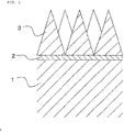
- An optical component according to the present disclosure includes a base 1, a moth-eye structure 3 with predetermined concavities and convexities, and at least one buffer layer 2 provided between the base 1 and the moth-eye structure 3 as defined in claim 1.
- a change in refractive index between the base 1 and a medium is adjusted by the buffer layer 2 and the moth-eye structure 3.
- optical component means a component that has a light-transmissive surface, such as a lens, a prism, a filter, a mirror, or a display.
- the base 1 has a predetermined function as an optical component element.
- the shape of the base is not limited to any particular one, and can be freely designed according to the function of the optical component and the application thereof, such as a plate shape like a display, and a curved shape like a lens.
- the material is also freely selectable according to the function of the optical component and the application thereof, but an optically transparent material within a visible light range between 400 nm and 780 nm is preferable since such a material is applicable to various optical applications.
- a material that contains silica glass and sapphire glass which have high ultraviolet light transmissivity is preferable.
- the term medium means a substance and a physical body that becomes a light propagation field, and is a gas like air that is in contact with the surface of the optical component (the surface of the moth-eye structure 3) and a liquid like water, but may be a vacuum.
- the moth-eye structure 3 is a microscopic concavo-convex structure similar to the shape of "an eye of a moth". Light is likely to be reflected at a part where a change in refractive index is large. Conversely, it is known that, when the concavo-convex structure of the moth-eye structure 3 is formed at a smaller cycle than the wavelength of a visible light range, light behaves as if an average refractive index obtained by averaging the refractive index of the medium at an arbitrary location in the vertical direction of the concavo-convex structure, and, the refractive index of the material applied to the moth-eye structure 3 is the refractive index at this location.
- Example concavo-convex structures applicable are cone shapes like a circular cone, conical trapezoids like a three-dimensional shape obtained by eliminating, from a cone, a cone with a common vertex to that of the former cone but scaled down similarly, and bombshell-like shapes having a side face expanded in the horizontal direction. Needless to say, the present disclosure is not limited to those shapes.
- conventionally well-known arbitrary methods are applicable, such as nano-imprinting, injection molding, and photolithography.
- At least one buffer layer 2 that is formed of a material with a refractive index lower than that of the base 1 but higher than that of the moth-eye structure 3 is formed between the base 1 and the moth-eye structure 3.
- the buffer layers 2 are arranged in such a way that the refractive index of the buffer layer 2 at the base-1 side is higher than that of the buffer layer 2 at the moth-eye-structure-3 side. The reason why such a structure is employed is to enable an application of a material that has a low refractive index to the moth-eye structure 3, thereby reducing a change in refractive index.
- the materials of the buffer layers 2 and moth-eye structure 3 are freely selectable, but for example, a material that has a refractive index adjusted by a siloxane-based material is applicable.
- any methods are applicable as long as the base 1 and the buffer layer 2 are in contact with each other intimately and uniformly, and for example, a thermosetting material with an adjusted refractive index may be applied by spin coating, and the such a material may be heated to form the buffer layer on the base.
- FIGS. 2 and 3 illustrate optical characteristics when the buffer layer 2 is present or is absent between the base 1 and the moth-eye structure 3.
- the optical characteristics a relationship between a wavelength of light and a ratio of an intensity of reflected light relative to incident light (reflected light/incident light) was measured.
- light light was emitted to the optical component at an incident angle of 0 degree (perpendicular to the optical component), and the relationship between the intensity of reflected light and the wavelength in the direction in which the incident angle was 0 degree was measured.
- measurements were made within a range between 400 nm and 700 nm that is a visible light range.
- an optical component that included the base 1 formed of a glass (PCD51) with a refractive index of 1.59, the buffer layer 2 formed of a siloxane-based material with a refractive index of 1.52, and the moth-eye structure 3 formed of a siloxane-based material with a refractive index of 1.47, and, as illustrated in FIG. 5 , an optical component (first comparative example) that included the base 1 formed of a glass with a refractive index of 1.59, and the moth-eye structure 3 formed of a siloxane-based material with a refractive index of 1.47 were applied.
- the applied moth-eye structure bomb-shell like concavities and convexities with a height of 220 nm, and a bottom diameter of 250 nm were arranged in a triangular shape at a pitch of 250 nm.
- the moth-eye structure was produced by nano-imprinting.
- the remaining thickness of the moth-eye structure 3 between the moth-eye structure 3 and the buffer layer 2 in the first example was 20 nm
- the thickness of the buffer layer 2 was 35 nm
- the remaining thickness of the moth-eye structure 3 between the moth-eye structure 3 and the base 1 in the first comparative example was 160 nm.
- the test was carried out under an atmospheric condition. That is, the medium was air that has a refractive index of 1.000.
- the optical component according to the first example provided with the buffer layer 2 further reduced reflection of light in comparison with the optical component according to the first comparative example which had no buffer layer 2.
- the inventors of the present disclosure further keenly examined, and consequently found that, as for the moth-eye structure 3, when the position of the interface of the moth-eye structure 3 at the base-1 side is 0, the shortest distance from the interface toward the moth-eye structure 3 is t, the refractive index of the base 1 is n s , the average refractive index of the moth-eye structure 3 at a location with the distance t from the interface is n t , the shortest distance from the interface to the vertex of the convexity of the moth-eye structure 3 is h, and the refractive index of the medium in contact with the surface of the moth-eye structure 3 is n M , the closer the refractive index n t is to the following formula (A), the higher the effect of reducing reflection of light from a broad range of angles becomes.
- n t n M + n S ⁇ n M t ⁇ h 2 h 2
- the inventors of the present disclosure also found that, when the refractive index n t is an error which is equal to or smaller than 15 % of a difference (n s -n M ) between the refractive index n s of the base 1 and the refractive index n M of the medium, an effect of reducing reflection of light incident from wider angles is sufficiently high in comparison with conventional technologies.
- this is expressed as a formula, the following formula (B) is obtained.
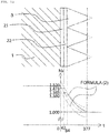
- the concavo-convex structure that satisfies the formula (A) is cones like circular cones.
- FIG. 6 illustrates a relationship between the formulae (A), (B) and the moth-eye structure 3 that satisfies the formula (A).
- FIG. 7 shows a simulation result of optical characteristics of an optical component (second example) that satisfies the formula (B)
- FIG. 8 shows a simulation result of optical characteristics of an optical component (second comparative example) that does not satisfy the formula (B).
- the optical characteristics a relationship between a wavelength of light and a ratio (reflected light/incident light) of the intensity of reflected light relative to incident light was calculated.
- light light was emitted to the optical component at an incident angle of 0, 15, 30, or 45 degrees, and a relationship between the intensity of reflected light and the wavelength in the direction in which the incident angle was 0 degree was calculated.
- the wavelength the calculation was made within a range between 400 nm to 700 nm that was a visible light range. Note that for a simulation, a software "DiffractMOD" released by Synopsys, Inc., was applied.
- the optical that included the base 1 and the moth-eye structure 3 both of which are formed of a material with a refractive index of 1.52 was applied.
- the moth-eye structure 3 of the optical component circular cone concavities and convexities which had a height of 450 nm, and a diameter of 200 nm were arranged in a triangular shape at a pitch of 200 nm (see FIG. 9 ) and bombshell-like concavities and convexities which had a height of 450 nm, and a diameter of 200 nm were arranged in a triangular shape at a pitch of 200 nm (see FIG. 10 ) so as to change the average refractive index linearly were applied.
- the medium present on the surface of the optical component was air that has a refractive index of 1.00.
- the average refractive index of the moth-eye structure 3 should be adjusted in such a way that the refractive index n t satisfies the following formula (1).
- the concavities and convexities of the moth-eye structure may be in an arbitrary shape, such as cones other than a circular cone, a conical trapezoid, or a bombshell-like shape.
- the error should be smaller, such as equal to or smaller than 10 %, equal to or smaller than 8 %, equal to or smaller than 5 %, equal to or smaller than 3 %, equal to or smaller than 2 %, and equal to or smaller than 1 %.
- the thickness of the buffer layer 2 and the refractive index thereof are also taken into consideration. That is, when the position of the interface between the base 1 and the buffer layer 2 is 0, the shortest distance from the interface toward the moth-eye structure is t, the refractive index of the base 1 is n s , the refractive index of the buffer layer 2 or the average refractive index of the moth-eye structure 3 at a location with the distance t from the interface is n t , the shortest distance from the interface to the vertex of the convexity of the moth-eye structure 3 is h, and and the refractive index of the medium in contact with the surface of the moth-eye structure 3 is n M , it is more preferable that the refractive index of the buffer layer 2 and the average refractive index of the moth-eye structure 3 should be adjusted in such a way that the refractive index n t
- the error should be smaller, such as equal to or smaller than 10 %, equal to or smaller than 8 %, equal to or smaller than 5 %, equal to or smaller than 3 %, equal to or smaller than 2 %, and equal to or smaller than 1 %.
- FIG. 11 shows a simulation result of optical characteristics of an optical component (third example) that satisfies the formula (2)
- FIG. 12 shows a simulation result of optical characteristics of an optical component (second comparative example) that does not satisfy the formula (2).
- the optical characteristics a relationship between a wavelength of light and a ratio (reflected light/incident light) of the intensity of reflected light relative to incident light was calculated.
- light light was emitted to the optical component at an incident angle of 0, 15, 30, or 45 degrees, and a relationship between the intensity of reflected light and the wavelength in the direction in which the incident angle was 0 degree was calculated.
- the wavelength the calculation was made within a range between 400 nm to 700 nm that was a visible light range. Note that for a simulation, a software "DiffractMOD" released by Synopsys, Inc., was applied.
- a material for the base 1 that had a refractive index of 1. 52 a material for a first buffer layer 21 that had a refractive index of 1.473, a material for the second buffer layer 22 that had a refractive index of 1.385, and a material for the moth-eye structure 3 that had a refractive index of 1.38 were applied (third example).
- a material for the base 1 that had a refractive index of 1.52 without a buffer layer
- a material for the moth-eye structure 3 that had a refractive index of 1.38 were applied (third comparative example).
- both of the third example and the third comparative example included circular cone trapezoids with a height of 293 nm that was obtained by eliminating, from circular cones with a height of 366 nm and a diameter of 200 nm, circular ones with a common vertex but scaled down similarly with a height of 73 nm and a diameter of 40 nm, and such circular cone trapezoids were arranged in a triangular shape at a pitch of 200 nm.
- Both of the first buffer layer 21 and the second buffer layer 22 had a thickness of 42 nm. Note that the medium present on the surface of the optical component was air that has a reflective index of 1.
Description
- The present disclosure relates to an optical component that reduces reflection of light from a surface, and a method of producing the same.
- In the case of transmissive optical components, such as light transmissive lenses and displays, solar light, illumination light, etc., are reflected from an interface that is in contact with air. This sometimes decreases a visibility. Hence, according to conventional technologies, a coating is applied to a surface of an optical component, and a moth-eye structure is provided on the surface in order to reduce reflection of light (see, for example, Patent Document 1).
-
Patent Document 2 discloses an optical member having a high antireflection effect on a base material with a low refractive index, in which a laminated body is formed on a base material surface. The laminated body has a porous surface layer or a layer having an uneven structure on the surface and a polymer layer having a specific thickness containing a maleimide copolymer between the porous layer or the layer having an uneven structure and the base material. -
Patent Document 3 discloses an optical element having a good reflection preventing function in a large wavelength region and a large incident angle range and generates little flares or ghosts. The optical element includes a reflection preventing structure constituted on at least one side of a light incoming/outgoing side of a substrate so that a fine uneven structure with an average pitch of the shortest wavelength λL or less is an outermost layer. The average pitch P of the fine uneven structure, the index of refraction n1 of a material forming the fine uneven structure, the average height h of the fine uneven structure and the incident angle Θ of a light flux entering the fine uneven structure from the air side are suitably set. -
- Patent Document 1:
JP 2014-51601 A - Patent Document 2:
WO 2014/084328 A - Patent Document 3:
JP 2010-078803 A - According to the conventional technologies, however, a capability of reducing reflection of light is still insufficient, and a further improvement has been desired. In addition, the conventional technologies are made in consideration of reflection only when the incident angle of light is constant, and a case in which the incident angle of light varies is out of consideration. When, for example, the incident angle of light is substantially 0 degree (vertical), reflection of light can be reduced, but it becomes more difficult to sufficiently reduce reflection as the incident angle increases more. Therefore, when the optical component has a curvature like a lens, and the incident angle of light varies, sufficient reduction of the reflection of light is not accomplished.
- Therefore, it is an objective of the present disclosure to provide an optical component that is capable of further reducing reflection of light, and a method of producing the same. In addition, it is another objective to provide an optical component that is capable of sufficiently reducing reflection of light although the incident angle of light varies, and a method of producing the same.
- In order to accomplish the above objectives, an optical component according to the present disclosure includes:
- a base;
- a moth-eye structure including predetermined concavities and convexities; and
- at least one buffer layer provided between the base and the moth-eye structure, and the buffer layer is formed of a material that has a refractive index lower than a refractive index of the base, but higher than a refractive index of the moth-eye structure,
- It is preferable that the moth-eye structure should be in a cone shape or is in a conical trapezoid shape.
- According to another aspect of the present disclosure, a method of producing an optical component that includes a base, a moth-eye structure with predetermined concavities and convexities, and at least one buffer layer provided between the base and the moth-eye structure as defined in
claim 3. - Still further, it is preferable that the moth-eye structure should be formed in a cone shape or is in a conical trapezoid shape.
- According to the present disclosure, there is provided an optical component that is capable of sufficiently reducing reflection of light by controlling a change in refractive index although the incident angle of light varies.
-
-
FIG. 1 is a side cross-sectional view illustrating an optical component according to the present disclosure; -
FIG. 2 is a diagram illustrating optical characteristics of the optical component according to the present disclosure; -
FIG. 3 is a diagram illustrating optical characteristics of a conventional optical component; -
FIG. 4 is a side cross-sectional view illustrating an optical component according to the present disclosure; -
FIG. 5 is a side cross-sectional view illustrating a conventional optical component; -
FIG. 6 is a diagram to explain a formula (A) and a formula (B); -
FIG. 7 is a diagram illustrating optical characteristics of an optical component that satisfies the formula (B); -
FIG. 8 is a diagram illustrating optical characteristics of an optical component that does not satisfy the formula (B) ; -
FIG. 9 is a diagram to explain an optical component that satisfies the formula (B); -
FIG. 10 is a diagram to explain an optical component that does not satisfy the formula (B); -
FIG. 11 is a diagram illustrating optical characteristics of an optical component that satisfies a formula (2) according to the present invention; -
FIG. 12 is a diagram illustrating optical characteristics of an optical component that does not satisfy the formula (2); -
FIG. 13 is a diagram to explain an optical component that satisfies the formula (2) according to the present invention; and -
FIG. 14 is a diagram to explain an optical component that does not satisfy the formula (2). - An optical component according to the present disclosure includes a
base 1, a moth-eye structure 3 with predetermined concavities and convexities, and at least onebuffer layer 2 provided between thebase 1 and the moth-eye structure 3 as defined inclaim 1. A change in refractive index between thebase 1 and a medium is adjusted by thebuffer layer 2 and the moth-eye structure 3. - In this case, the term optical component means a component that has a light-transmissive surface, such as a lens, a prism, a filter, a mirror, or a display.
- The
base 1 has a predetermined function as an optical component element. The shape of the base is not limited to any particular one, and can be freely designed according to the function of the optical component and the application thereof, such as a plate shape like a display, and a curved shape like a lens. The material is also freely selectable according to the function of the optical component and the application thereof, but an optically transparent material within a visible light range between 400 nm and 780 nm is preferable since such a material is applicable to various optical applications. When the optical component is utilized within an ultraviolet light range, a material that contains silica glass and sapphire glass which have high ultraviolet light transmissivity is preferable. - The term medium means a substance and a physical body that becomes a light propagation field, and is a gas like air that is in contact with the surface of the optical component (the surface of the moth-eye structure 3) and a liquid like water, but may be a vacuum.
- The moth-
eye structure 3 is a microscopic concavo-convex structure similar to the shape of "an eye of a moth". Light is likely to be reflected at a part where a change in refractive index is large. Conversely, it is known that, when the concavo-convex structure of the moth-eye structure 3 is formed at a smaller cycle than the wavelength of a visible light range, light behaves as if an average refractive index obtained by averaging the refractive index of the medium at an arbitrary location in the vertical direction of the concavo-convex structure, and, the refractive index of the material applied to the moth-eye structure 3 is the refractive index at this location. Hence, when the concavo-convex structure of the moth-eye structure 3 is formed so as to change the average refractive index gradually, a sharp change in refractive index is eliminated, and thus reflection of incident light can be reduced. Example concavo-convex structures applicable are cone shapes like a circular cone, conical trapezoids like a three-dimensional shape obtained by eliminating, from a cone, a cone with a common vertex to that of the former cone but scaled down similarly, and bombshell-like shapes having a side face expanded in the horizontal direction. Needless to say, the present disclosure is not limited to those shapes. As for how to produce the moth-eye structure, conventionally well-known arbitrary methods are applicable, such as nano-imprinting, injection molding, and photolithography. - In this case, the more the change in refractive index is gentle, the more the moth-
eye structure 3 reduces reflection of light from the surface. Hence, when the respective refractive indexes of materials applied to the moth-eye structure 3 are the same, the longer the distance between the surface of thebase 1 and the vertex of the convexity of the moth-eye structure 3 is, the more the reflection of light is reduced. However, by elongating such a distance only by the moth-eye structure 3, accomplishment of such a structure is not easy due to technical constraints in processes. Hence, according to the optical component of the present disclosure, as illustrated inFIG. 1 , at least onebuffer layer 2 that is formed of a material with a refractive index lower than that of thebase 1 but higher than that of the moth-eye structure 3 is formed between thebase 1 and the moth-eye structure 3. In addition, when equal to or greater than twobuffer layers 2 are to be formed, the buffer layers 2 are arranged in such a way that the refractive index of thebuffer layer 2 at the base-1 side is higher than that of thebuffer layer 2 at the moth-eye-structure-3 side. The reason why such a structure is employed is to enable an application of a material that has a low refractive index to the moth-eye structure 3, thereby reducing a change in refractive index. The materials of the buffer layers 2 and moth-eye structure 3 are freely selectable, but for example, a material that has a refractive index adjusted by a siloxane-based material is applicable. - As for how to form the
buffer layer 2 on thebase 1, any methods are applicable as long as thebase 1 and thebuffer layer 2 are in contact with each other intimately and uniformly, and for example, a thermosetting material with an adjusted refractive index may be applied by spin coating, and the such a material may be heated to form the buffer layer on the base. -
FIGS. 2 and3 illustrate optical characteristics when thebuffer layer 2 is present or is absent between thebase 1 and the moth-eye structure 3. As for the optical characteristics, a relationship between a wavelength of light and a ratio of an intensity of reflected light relative to incident light (reflected light/incident light) was measured. As for light, light was emitted to the optical component at an incident angle of 0 degree (perpendicular to the optical component), and the relationship between the intensity of reflected light and the wavelength in the direction in which the incident angle was 0 degree was measured. As for the wavelength, measurements were made within a range between 400 nm and 700 nm that is a visible light range. - As for the optical component, as illustrated in
FIG. 4 , an optical component (first example) that included thebase 1 formed of a glass (PCD51) with a refractive index of 1.59, thebuffer layer 2 formed of a siloxane-based material with a refractive index of 1.52, and the moth-eye structure 3 formed of a siloxane-based material with a refractive index of 1.47, and, as illustrated inFIG. 5 , an optical component (first comparative example) that included thebase 1 formed of a glass with a refractive index of 1.59, and the moth-eye structure 3 formed of a siloxane-based material with a refractive index of 1.47 were applied. In this case, as for the applied moth-eye structure 3, bomb-shell like concavities and convexities with a height of 220 nm, and a bottom diameter of 250 nm were arranged in a triangular shape at a pitch of 250 nm. The moth-eye structure was produced by nano-imprinting. In addition, the remaining thickness of the moth-eye structure 3 between the moth-eye structure 3 and thebuffer layer 2 in the first example was 20 nm, and the thickness of thebuffer layer 2 was 35 nm, while the remaining thickness of the moth-eye structure 3 between the moth-eye structure 3 and thebase 1 in the first comparative example was 160 nm. The test was carried out under an atmospheric condition. That is, the medium was air that has a refractive index of 1.000. - As illustrated in
FIGS. 2 and3 , it becomes clear that the optical component according to the first example provided with thebuffer layer 2 further reduced reflection of light in comparison with the optical component according to the first comparative example which had nobuffer layer 2. - In addition, the inventors of the present disclosure further keenly examined, and consequently found that, as for the moth-
eye structure 3, when the position of the interface of the moth-eye structure 3 at the base-1 side is 0, the shortest distance from the interface toward the moth-eye structure 3 is t, the refractive index of thebase 1 is ns, the average refractive index of the moth-eye structure 3 at a location with the distance t from the interface is nt, the shortest distance from the interface to the vertex of the convexity of the moth-eye structure 3 is h, and the refractive index of the medium in contact with the surface of the moth-eye structure 3 is nM, the closer the refractive index nt is to the following formula (A), the higher the effect of reducing reflection of light from a broad range of angles becomes.
- Still further, the inventors of the present disclosure also found that, when the refractive index nt is an error which is equal to or smaller than 15 % of a difference (ns-nM) between the refractive index ns of the
base 1 and the refractive index nM of the medium, an effect of reducing reflection of light incident from wider angles is sufficiently high in comparison with conventional technologies. When this is expressed as a formula, the following formula (B) is obtained.
- Note that, in the moth-
eye structure 3, the concavo-convex structure that satisfies the formula (A) is cones like circular cones.FIG. 6 illustrates a relationship between the formulae (A), (B) and the moth-eye structure 3 that satisfies the formula (A). -
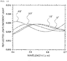
FIG. 7 shows a simulation result of optical characteristics of an optical component (second example) that satisfies the formula (B), andFIG. 8 shows a simulation result of optical characteristics of an optical component (second comparative example) that does not satisfy the formula (B). As for the optical characteristics, a relationship between a wavelength of light and a ratio (reflected light/incident light) of the intensity of reflected light relative to incident light was calculated. As for light, light was emitted to the optical component at an incident angle of 0, 15, 30, or 45 degrees, and a relationship between the intensity of reflected light and the wavelength in the direction in which the incident angle was 0 degree was calculated. As for the wavelength, the calculation was made within a range between 400 nm to 700 nm that was a visible light range. Note that for a simulation, a software "DiffractMOD" released by Synopsys, Inc., was applied. - In addition, as for the simulation, the optical that included the
base 1 and the moth-eye structure 3 both of which are formed of a material with a refractive index of 1.52 was applied. Still further, as for the moth-eye structure 3 of the optical component, circular cone concavities and convexities which had a height of 450 nm, and a diameter of 200 nm were arranged in a triangular shape at a pitch of 200 nm (seeFIG. 9 ) and bombshell-like concavities and convexities which had a height of 450 nm, and a diameter of 200 nm were arranged in a triangular shape at a pitch of 200 nm (seeFIG. 10 ) so as to change the average refractive index linearly were applied. Note that the medium present on the surface of the optical component was air that has a refractive index of 1.00. - Based on a comparison of results shown in
FIG. 7 and inFIG. 8 , it becomes clear that the optical component according to the second example further sufficiently reduced reflection of light although the incident angle of light changed. - Hence, according to an optical component of the present disclosure (not claimed), in consideration of the
buffer layer 2 present between thebase 1 and the moth-eye structure 3, when the position of the interface (bottom of concavities and convexities) of the moth-eye structure 3 at the base-1 side is 0, the shortest distance from the interface toward the moth-eye structure 3 is t, the refractive index of theclosest buffer layer 2 to the moth-eye structure 3 is nB, an average refractive index of the moth-eye structure 3 at a location with the distance t from the interface is nt, the shortest distance from the interface to the vertex of the convexity of the moth-eye structure 3 is h, and the refractive index of the medium in contact with the surface of the moth-eye structure 3 is nM, it is preferable that the average refractive index of the moth-eye structure 3 should be adjusted in such a way that the refractive index nt satisfies the following formula (1).
- Note that, as long as the formula (1) is satisfied, the concavities and convexities of the moth-eye structure may be in an arbitrary shape, such as cones other than a circular cone, a conical trapezoid, or a bombshell-like shape. In addition, it is preferable that the error should be smaller, such as equal to or smaller than 10 %, equal to or smaller than 8 %, equal to or smaller than 5 %, equal to or smaller than 3 %, equal to or smaller than 2 %, and equal to or smaller than 1 %.
- In addition, in the formula (1), only the height of the moth-
eye structure 3 is taken into consideration, but according to the invention the thickness of thebuffer layer 2 and the refractive index thereof are also taken into consideration. That is, when the position of the interface between thebase 1 and thebuffer layer 2 is 0, the shortest distance from the interface toward the moth-eye structure is t, the refractive index of thebase 1 is ns, the refractive index of thebuffer layer 2 or the average refractive index of the moth-eye structure 3 at a location with the distance t from the interface is nt, the shortest distance from the interface to the vertex of the convexity of the moth-eye structure 3 is h, and and the refractive index of the medium in contact with the surface of the moth-eye structure 3 is nM, it is more preferable that the refractive index of thebuffer layer 2 and the average refractive index of the moth-eye structure 3 should be adjusted in such a way that the refractive index nt satisfies the following formula (2) .
- In this case, also, it is preferable that the error should be smaller, such as equal to or smaller than 10 %, equal to or smaller than 8 %, equal to or smaller than 5 %, equal to or smaller than 3 %, equal to or smaller than 2 %, and equal to or smaller than 1 %.
-
FIG. 11 shows a simulation result of optical characteristics of an optical component (third example) that satisfies the formula (2), andFIG. 12 shows a simulation result of optical characteristics of an optical component (second comparative example) that does not satisfy the formula (2). As for the optical characteristics, a relationship between a wavelength of light and a ratio (reflected light/incident light) of the intensity of reflected light relative to incident light was calculated. As for light, light was emitted to the optical component at an incident angle of 0, 15, 30, or 45 degrees, and a relationship between the intensity of reflected light and the wavelength in the direction in which the incident angle was 0 degree was calculated. As for the wavelength, the calculation was made within a range between 400 nm to 700 nm that was a visible light range. Note that for a simulation, a software "DiffractMOD" released by Synopsys, Inc., was applied. - In addition, as for the simulation, as illustrated in
FIG. 13 , with respect to the optical component, a material for thebase 1 that had a refractive index of 1. 52 , a material for afirst buffer layer 21 that had a refractive index of 1.473, a material for thesecond buffer layer 22 that had a refractive index of 1.385, and a material for the moth-eye structure 3 that had a refractive index of 1.38 were applied (third example). In addition, as illustrated inFIG. 14 , without a buffer layer, a material for thebase 1 that had a refractive index of 1.52, and a material for the moth-eye structure 3 that had a refractive index of 1.38 were applied (third comparative example). Still further, as for the moth-eye structure 3 of the optical component, both of the third example and the third comparative example included circular cone trapezoids with a height of 293 nm that was obtained by eliminating, from circular cones with a height of 366 nm and a diameter of 200 nm, circular ones with a common vertex but scaled down similarly with a height of 73 nm and a diameter of 40 nm, and such circular cone trapezoids were arranged in a triangular shape at a pitch of 200 nm. Both of thefirst buffer layer 21 and thesecond buffer layer 22 had a thickness of 42 nm. Note that the medium present on the surface of the optical component was air that has a reflective index of 1. - Based on a comparison between the result in
FIG. 11 and the result inFIG. 12 , it becomes clear that the optical component according to the third example further sufficiently reduced reflection of light although the incident angle of light changed. -
- 1
- Base
- 2
- Buffer layer
- 3
- Moth-eye structure
- 21
- First buffer layer
- 22
- Second buffer layer
when a position of an interface between the base and the buffer layer is 0, a shortest distance from the interface toward the moth-eye structure is t, a refractive index of the base is ns, a refractive index of the buffer layer or an average refractive index of the moth-eye structure at a location with the distance t from the interface is nt, a shortest distance from the interface to a vertex of the convexity of the moth-eye structure is h, and and a refractive index of a medium in contact with a surface of the moth-eye structure is nM, the refractive index of the buffer layer and the average refractive index of the moth-eye structure are adjusted in such a way that the refractive index nt satisfies a following formula (2):

Claims (4)
- An optical component comprising:a base;a moth-eye structure comprising predetermined concavities and convexities; andat least one buffer layer provided between the base and the moth-eye structure, the buffer layer being formed of a material that has a refractive index lower than a refractive index of the base, but higher than a refractive index of the moth-eye structure,characterized in thatwhen a position of an interface between the base and the buffer layer is 0, a shortest distance from the interface toward the moth-eye structure is t, a refractive index of the base is ns, a refractive index of the buffer layer or an average refractive index of the moth-eye structure at a location with the distance t from the interface is nt, a shortest distance from the interface to a vertex of the convexity of the moth-eye structure is h, and and a refractive index of a medium in contact with a surface of the moth-eye structure is nM, the refractive index of the buffer layer and the average refractive index of the moth-eye structure are adjusted in such a way that the refractive index nt satisfies a following formula (2):

- The optical component according to claim 1, wherein the moth-eye structure is in a cone shape or is in a conical trapezoid shape.
- A method for producing an optical component that comprises a base, a moth-eye structure with predetermined concavities and convexities, and at least one buffer layer provided between the base and the moth-eye structure, the method comprising:applying as a material of the buffer layer, a material that has a refractive index lower than a refractive index of the base, but higher than a refractive index of the moth-eye structure,
characterized in thatwhen a position of an interface between the base and the buffer layer is 0, a shortest distance from the interface toward the moth-eye structure is t, a refractive index of the base is ns, a refractive index of the buffer layer or an average refractive index of the moth-eye structure at a location with the distance t from the interface is nt, a shortest distance from the interface to a vertex of the convexity of the moth-eye structure is h, and and a refractive index of a medium in contact with a surface of the moth-eye structure is nM, the refractive index of the buffer layer and the average refractive index of the moth-eye structure are adjusted in such a way that the refractive index nt satisfies a following formula (2):
- The optical component according to claim 3, wherein the moth-eye structure is formed in a cone shape or is in a conical trapezoid shape.
Applications Claiming Priority (2)
| Application Number | Priority Date | Filing Date | Title |
|---|---|---|---|
| JP2014141958 | 2014-07-10 | ||
| PCT/JP2015/069750 WO2016006651A1 (en) | 2014-07-10 | 2015-07-09 | Optical element and method for producing same |
Publications (3)
| Publication Number | Publication Date |
|---|---|
| EP3168656A1 EP3168656A1 (en) | 2017-05-17 |
| EP3168656A4 EP3168656A4 (en) | 2018-03-21 |
| EP3168656B1 true EP3168656B1 (en) | 2019-04-17 |
Family
ID=55064279
Family Applications (1)
| Application Number | Title | Priority Date | Filing Date |
|---|---|---|---|
| EP15785043.9A Not-in-force EP3168656B1 (en) | 2014-07-10 | 2015-07-09 | Optical element and method for producing same |
Country Status (6)
| Country | Link |
|---|---|
| US (1) | US9851474B2 (en) |
| EP (1) | EP3168656B1 (en) |
| JP (1) | JPWO2016006651A1 (en) |
| KR (1) | KR20170030473A (en) |
| CN (1) | CN106662673B (en) |
| WO (1) | WO2016006651A1 (en) |
Families Citing this family (3)
| Publication number | Priority date | Publication date | Assignee | Title |
|---|---|---|---|---|
| US20200309995A1 (en) * | 2019-03-26 | 2020-10-01 | Facebook Technologies, Llc | Anti-reflective coatings for transparent electroactive transducers |
| KR20220022303A (en) | 2020-08-18 | 2022-02-25 | 삼성전기주식회사 | Camera Module and Portable Terminal |
| CN115598794A (en) * | 2021-07-09 | 2023-01-13 | 大立光电股份有限公司(Tw) | Imaging lens and electronic device |
Family Cites Families (25)
| Publication number | Priority date | Publication date | Assignee | Title |
|---|---|---|---|---|
| US7145721B2 (en) * | 2000-11-03 | 2006-12-05 | Mems Optical, Inc. | Anti-reflective structures |
| JP4506070B2 (en) * | 2002-11-01 | 2010-07-21 | コニカミノルタホールディングス株式会社 | Method for forming antiglare layer, method for producing antiglare film, and ink jet device for forming antiglare layer |
| JP2007264594A (en) * | 2006-03-01 | 2007-10-11 | Nissan Motor Co Ltd | Anti-reflection fine structure, anti-reflection molded body, method of producing the same |
| EP1921470A3 (en) * | 2006-11-08 | 2011-11-30 | Nissan Motor Co., Ltd. | Water Repellent Anti-Reflective Structure and Method of Manufacturing the Same |
| JP2009075539A (en) * | 2007-08-28 | 2009-04-09 | Nissan Motor Co Ltd | Anti-reflective structure and anti-reflective molded body |
| US7940462B2 (en) * | 2007-08-28 | 2011-05-10 | Nissan Motor Co., Ltd. | Antireflective structure and antireflective molded body |
| JP2010078803A (en) * | 2008-09-25 | 2010-04-08 | Canon Inc | Optical element and optical system having it |
| JP5257066B2 (en) * | 2008-12-26 | 2013-08-07 | ソニー株式会社 | Optical element, display device, optical component with antireflection function, and master |
| JP2011053496A (en) * | 2009-09-02 | 2011-03-17 | Sony Corp | Optical device, manufacturing method thereof, and method of manufacturing master |
| JP5511307B2 (en) * | 2009-10-23 | 2014-06-04 | キヤノン株式会社 | Optical member and manufacturing method thereof |
| JP4991943B2 (en) * | 2010-02-26 | 2012-08-08 | キヤノン株式会社 | Optical member, polyimide, and manufacturing method thereof |
| JP5773576B2 (en) * | 2010-04-01 | 2015-09-02 | キヤノン株式会社 | Anti-reflection structure and optical equipment |
| JP2012189846A (en) * | 2011-03-11 | 2012-10-04 | Tamron Co Ltd | Antireflection optical element and method for manufacturing antireflection optical element |
| CN103688193B (en) * | 2011-05-17 | 2016-05-04 | 佳能电子株式会社 | Optical filter, optical device, electronic equipment and antireflection complex |
| US9588266B2 (en) * | 2011-05-17 | 2017-03-07 | Canon Denshi Kabushiki Kaisha | Optical filter and optical apparatus |
| JP5840448B2 (en) * | 2011-10-12 | 2016-01-06 | 株式会社タムロン | Antireflection film and method of manufacturing antireflection film |
| KR101852659B1 (en) * | 2012-03-15 | 2018-04-26 | 소켄 케미칼 앤드 엔지니어링 캄파니, 리미티드 | Anti-reflection film |
| KR101763460B1 (en) * | 2012-04-02 | 2017-07-31 | 아사히 가세이 가부시키가이샤 | Optical substrate, semiconductor light-emitting element, and method for producing semiconductor light-emitting element |
| EP2851714A4 (en) * | 2012-05-18 | 2015-07-01 | Mitsubishi Rayon Co | Film, method for producing same, plate-like product, image display device, and solar cell |
| JP2014051601A (en) | 2012-09-07 | 2014-03-20 | Nippon Shokubai Co Ltd | Optical formed body |
| JP6189612B2 (en) * | 2012-10-17 | 2017-08-30 | 富士フイルム株式会社 | Optical member provided with antireflection film and method for manufacturing the same |
| JP6164824B2 (en) * | 2012-11-30 | 2017-07-19 | キヤノン株式会社 | Optical member and manufacturing method thereof |
| US20150103396A1 (en) * | 2013-05-01 | 2015-04-16 | Byron Zollars | Antireflective Structures for Optics |
| JP2015068853A (en) * | 2013-09-26 | 2015-04-13 | ソニー株式会社 | Laminated body, imaging element package, imaging apparatus, and electronic apparatus |
| US9880328B2 (en) * | 2013-12-12 | 2018-01-30 | Corning Incorporated | Transparent diffusers for lightguides and luminaires |
-
2015
- 2015-07-09 CN CN201580026483.5A patent/CN106662673B/en not_active Expired - Fee Related
- 2015-07-09 JP JP2016532965A patent/JPWO2016006651A1/en active Pending
- 2015-07-09 EP EP15785043.9A patent/EP3168656B1/en not_active Not-in-force
- 2015-07-09 KR KR1020167032002A patent/KR20170030473A/en unknown
- 2015-07-09 US US14/889,914 patent/US9851474B2/en active Active
- 2015-07-09 WO PCT/JP2015/069750 patent/WO2016006651A1/en active Application Filing
Non-Patent Citations (1)
| Title |
|---|
| None * |
Also Published As
| Publication number | Publication date |
|---|---|
| CN106662673B (en) | 2018-11-30 |
| KR20170030473A (en) | 2017-03-17 |
| US9851474B2 (en) | 2017-12-26 |
| WO2016006651A1 (en) | 2016-01-14 |
| CN106662673A (en) | 2017-05-10 |
| US20170108623A1 (en) | 2017-04-20 |
| JPWO2016006651A1 (en) | 2017-04-27 |
| EP3168656A1 (en) | 2017-05-17 |
| EP3168656A4 (en) | 2018-03-21 |
Similar Documents
| Publication | Publication Date | Title |
|---|---|---|
| Li et al. | Antireflective surfaces based on biomimetic nanopillared arrays | |
| CN110651204B (en) | Diffraction grating with variable diffraction efficiency and method for displaying an image | |
| JP5170495B2 (en) | Antireflection microstructure and antireflection structure | |
| JP3201038U (en) | Optical film | |
| US9880328B2 (en) | Transparent diffusers for lightguides and luminaires | |
| KR101578244B1 (en) | Light control film with off-axis visible indicia | |
| JP2007264594A (en) | Anti-reflection fine structure, anti-reflection molded body, method of producing the same | |
| EP3168656B1 (en) | Optical element and method for producing same | |
| JP2008090212A (en) | Antireflection optical structure, antireflection optical structure body and its manufacturing method | |
| JP2008158293A (en) | Hydrophilic antireflection structure | |
| JP2009075539A (en) | Anti-reflective structure and anti-reflective molded body | |
| JP5612123B2 (en) | Light guide, lighting device having light guide, and display device | |
| WO2019196077A1 (en) | Low-refractive-index all-dielectric flat lens manufacturing method | |
| CN106662674B (en) | Optical element | |
| CN104950375A (en) | Upper polarizing plate for liquid crystal display and liquid crystal display | |
| JP2009198627A (en) | Anti-reflective structure and anti-reflective molded body | |
| CN109387889A (en) | Anti-reflection structure, display device and anti-reflection structure production method | |
| JP2018518699A (en) | Optical film | |
| JP2009198626A (en) | Anti-reflective structure and anti-reflective molded body | |
| JP7371639B2 (en) | Reflective transparent screen and video display system | |
| US20230221462A1 (en) | Metasurface optical device with tilted nano-structure units and optical apparatus | |
| EP3130946A1 (en) | Optical member and method for manufacturing same | |
| CN106772709B (en) | A kind of preparation method of display device and optical thin film therein | |
| JP2011516917A (en) | Beam splitter to compensate offset | |
| WO2017126673A1 (en) | Functional structural body |
Legal Events
| Date | Code | Title | Description |
|---|---|---|---|
| STAA | Information on the status of an ep patent application or granted ep patent |
Free format text: STATUS: THE INTERNATIONAL PUBLICATION HAS BEEN MADE |
|
| PUAI | Public reference made under article 153(3) epc to a published international application that has entered the european phase |
Free format text: ORIGINAL CODE: 0009012 |
|
| STAA | Information on the status of an ep patent application or granted ep patent |
Free format text: STATUS: REQUEST FOR EXAMINATION WAS MADE |
|
| 17P | Request for examination filed |
Effective date: 20151105 |
|
| AK | Designated contracting states |
Kind code of ref document: A1 Designated state(s): AL AT BE BG CH CY CZ DE DK EE ES FI FR GB GR HR HU IE IS IT LI LT LU LV MC MK MT NL NO PL PT RO RS SE SI SK SM TR |
|
| AX | Request for extension of the european patent |
Extension state: BA ME |
|
| DAV | Request for validation of the european patent (deleted) | ||
| DAX | Request for extension of the european patent (deleted) | ||
| A4 | Supplementary search report drawn up and despatched |
Effective date: 20180219 |
|
| RIC1 | Information provided on ipc code assigned before grant |
Ipc: G02B 1/118 20150101AFI20180213BHEP |
|
| GRAP | Despatch of communication of intention to grant a patent |
Free format text: ORIGINAL CODE: EPIDOSNIGR1 |
|
| STAA | Information on the status of an ep patent application or granted ep patent |
Free format text: STATUS: GRANT OF PATENT IS INTENDED |
|
| INTG | Intention to grant announced |
Effective date: 20181221 |
|
| GRAS | Grant fee paid |
Free format text: ORIGINAL CODE: EPIDOSNIGR3 |
|
| GRAA | (expected) grant |
Free format text: ORIGINAL CODE: 0009210 |
|
| STAA | Information on the status of an ep patent application or granted ep patent |
Free format text: STATUS: THE PATENT HAS BEEN GRANTED |
|
| AK | Designated contracting states |
Kind code of ref document: B1 Designated state(s): AL AT BE BG CH CY CZ DE DK EE ES FI FR GB GR HR HU IE IS IT LI LT LU LV MC MK MT NL NO PL PT RO RS SE SI SK SM TR |
|
| REG | Reference to a national code |
Ref country code: GB Ref legal event code: FG4D |
|
| REG | Reference to a national code |
Ref country code: CH Ref legal event code: EP |
|
| REG | Reference to a national code |
Ref country code: DE Ref legal event code: R096 Ref document number: 602015028537 Country of ref document: DE |
|
| REG | Reference to a national code |
Ref country code: AT Ref legal event code: REF Ref document number: 1122197 Country of ref document: AT Kind code of ref document: T Effective date: 20190515 Ref country code: IE Ref legal event code: FG4D |
|
| REG | Reference to a national code |
Ref country code: NL Ref legal event code: MP Effective date: 20190417 |
|
| REG | Reference to a national code |
Ref country code: LT Ref legal event code: MG4D |
|
| PG25 | Lapsed in a contracting state [announced via postgrant information from national office to epo] |
Ref country code: NL Free format text: LAPSE BECAUSE OF FAILURE TO SUBMIT A TRANSLATION OF THE DESCRIPTION OR TO PAY THE FEE WITHIN THE PRESCRIBED TIME-LIMIT Effective date: 20190417 |
|
| PG25 | Lapsed in a contracting state [announced via postgrant information from national office to epo] |
Ref country code: HR Free format text: LAPSE BECAUSE OF FAILURE TO SUBMIT A TRANSLATION OF THE DESCRIPTION OR TO PAY THE FEE WITHIN THE PRESCRIBED TIME-LIMIT Effective date: 20190417 Ref country code: LT Free format text: LAPSE BECAUSE OF FAILURE TO SUBMIT A TRANSLATION OF THE DESCRIPTION OR TO PAY THE FEE WITHIN THE PRESCRIBED TIME-LIMIT Effective date: 20190417 Ref country code: ES Free format text: LAPSE BECAUSE OF FAILURE TO SUBMIT A TRANSLATION OF THE DESCRIPTION OR TO PAY THE FEE WITHIN THE PRESCRIBED TIME-LIMIT Effective date: 20190417 Ref country code: NO Free format text: LAPSE BECAUSE OF FAILURE TO SUBMIT A TRANSLATION OF THE DESCRIPTION OR TO PAY THE FEE WITHIN THE PRESCRIBED TIME-LIMIT Effective date: 20190717 Ref country code: FI Free format text: LAPSE BECAUSE OF FAILURE TO SUBMIT A TRANSLATION OF THE DESCRIPTION OR TO PAY THE FEE WITHIN THE PRESCRIBED TIME-LIMIT Effective date: 20190417 Ref country code: AL Free format text: LAPSE BECAUSE OF FAILURE TO SUBMIT A TRANSLATION OF THE DESCRIPTION OR TO PAY THE FEE WITHIN THE PRESCRIBED TIME-LIMIT Effective date: 20190417 Ref country code: PT Free format text: LAPSE BECAUSE OF FAILURE TO SUBMIT A TRANSLATION OF THE DESCRIPTION OR TO PAY THE FEE WITHIN THE PRESCRIBED TIME-LIMIT Effective date: 20190817 Ref country code: SE Free format text: LAPSE BECAUSE OF FAILURE TO SUBMIT A TRANSLATION OF THE DESCRIPTION OR TO PAY THE FEE WITHIN THE PRESCRIBED TIME-LIMIT Effective date: 20190417 |
|
| PG25 | Lapsed in a contracting state [announced via postgrant information from national office to epo] |
Ref country code: BG Free format text: LAPSE BECAUSE OF FAILURE TO SUBMIT A TRANSLATION OF THE DESCRIPTION OR TO PAY THE FEE WITHIN THE PRESCRIBED TIME-LIMIT Effective date: 20190717 Ref country code: GR Free format text: LAPSE BECAUSE OF FAILURE TO SUBMIT A TRANSLATION OF THE DESCRIPTION OR TO PAY THE FEE WITHIN THE PRESCRIBED TIME-LIMIT Effective date: 20190718 Ref country code: PL Free format text: LAPSE BECAUSE OF FAILURE TO SUBMIT A TRANSLATION OF THE DESCRIPTION OR TO PAY THE FEE WITHIN THE PRESCRIBED TIME-LIMIT Effective date: 20190417 Ref country code: LV Free format text: LAPSE BECAUSE OF FAILURE TO SUBMIT A TRANSLATION OF THE DESCRIPTION OR TO PAY THE FEE WITHIN THE PRESCRIBED TIME-LIMIT Effective date: 20190417 Ref country code: RS Free format text: LAPSE BECAUSE OF FAILURE TO SUBMIT A TRANSLATION OF THE DESCRIPTION OR TO PAY THE FEE WITHIN THE PRESCRIBED TIME-LIMIT Effective date: 20190417 |
|
| REG | Reference to a national code |
Ref country code: AT Ref legal event code: MK05 Ref document number: 1122197 Country of ref document: AT Kind code of ref document: T Effective date: 20190417 |
|
| PG25 | Lapsed in a contracting state [announced via postgrant information from national office to epo] |
Ref country code: IS Free format text: LAPSE BECAUSE OF FAILURE TO SUBMIT A TRANSLATION OF THE DESCRIPTION OR TO PAY THE FEE WITHIN THE PRESCRIBED TIME-LIMIT Effective date: 20190817 |
|
| REG | Reference to a national code |
Ref country code: DE Ref legal event code: R097 Ref document number: 602015028537 Country of ref document: DE |
|
| PG25 | Lapsed in a contracting state [announced via postgrant information from national office to epo] |
Ref country code: EE Free format text: LAPSE BECAUSE OF FAILURE TO SUBMIT A TRANSLATION OF THE DESCRIPTION OR TO PAY THE FEE WITHIN THE PRESCRIBED TIME-LIMIT Effective date: 20190417 Ref country code: AT Free format text: LAPSE BECAUSE OF FAILURE TO SUBMIT A TRANSLATION OF THE DESCRIPTION OR TO PAY THE FEE WITHIN THE PRESCRIBED TIME-LIMIT Effective date: 20190417 Ref country code: RO Free format text: LAPSE BECAUSE OF FAILURE TO SUBMIT A TRANSLATION OF THE DESCRIPTION OR TO PAY THE FEE WITHIN THE PRESCRIBED TIME-LIMIT Effective date: 20190417 Ref country code: CZ Free format text: LAPSE BECAUSE OF FAILURE TO SUBMIT A TRANSLATION OF THE DESCRIPTION OR TO PAY THE FEE WITHIN THE PRESCRIBED TIME-LIMIT Effective date: 20190417 Ref country code: SK Free format text: LAPSE BECAUSE OF FAILURE TO SUBMIT A TRANSLATION OF THE DESCRIPTION OR TO PAY THE FEE WITHIN THE PRESCRIBED TIME-LIMIT Effective date: 20190417 Ref country code: DK Free format text: LAPSE BECAUSE OF FAILURE TO SUBMIT A TRANSLATION OF THE DESCRIPTION OR TO PAY THE FEE WITHIN THE PRESCRIBED TIME-LIMIT Effective date: 20190417 |
|
| REG | Reference to a national code |
Ref country code: DE Ref legal event code: R119 Ref document number: 602015028537 Country of ref document: DE |
|
| PLBE | No opposition filed within time limit |
Free format text: ORIGINAL CODE: 0009261 |
|
| STAA | Information on the status of an ep patent application or granted ep patent |
Free format text: STATUS: NO OPPOSITION FILED WITHIN TIME LIMIT |
|
| PG25 | Lapsed in a contracting state [announced via postgrant information from national office to epo] |
Ref country code: SM Free format text: LAPSE BECAUSE OF FAILURE TO SUBMIT A TRANSLATION OF THE DESCRIPTION OR TO PAY THE FEE WITHIN THE PRESCRIBED TIME-LIMIT Effective date: 20190417 Ref country code: IT Free format text: LAPSE BECAUSE OF FAILURE TO SUBMIT A TRANSLATION OF THE DESCRIPTION OR TO PAY THE FEE WITHIN THE PRESCRIBED TIME-LIMIT Effective date: 20190417 Ref country code: MC Free format text: LAPSE BECAUSE OF FAILURE TO SUBMIT A TRANSLATION OF THE DESCRIPTION OR TO PAY THE FEE WITHIN THE PRESCRIBED TIME-LIMIT Effective date: 20190417 |
|
| REG | Reference to a national code |
Ref country code: CH Ref legal event code: PL |
|
| 26N | No opposition filed |
Effective date: 20200120 |
|
| GBPC | Gb: european patent ceased through non-payment of renewal fee |
Effective date: 20190717 |
|
| PG25 | Lapsed in a contracting state [announced via postgrant information from national office to epo] |
Ref country code: TR Free format text: LAPSE BECAUSE OF FAILURE TO SUBMIT A TRANSLATION OF THE DESCRIPTION OR TO PAY THE FEE WITHIN THE PRESCRIBED TIME-LIMIT Effective date: 20190417 |
|
| REG | Reference to a national code |
Ref country code: BE Ref legal event code: MM Effective date: 20190731 |
|
| PG25 | Lapsed in a contracting state [announced via postgrant information from national office to epo] |
Ref country code: GB Free format text: LAPSE BECAUSE OF NON-PAYMENT OF DUE FEES Effective date: 20190717 Ref country code: DE Free format text: LAPSE BECAUSE OF NON-PAYMENT OF DUE FEES Effective date: 20200201 |
|
| PG25 | Lapsed in a contracting state [announced via postgrant information from national office to epo] |
Ref country code: BE Free format text: LAPSE BECAUSE OF NON-PAYMENT OF DUE FEES Effective date: 20190731 Ref country code: SI Free format text: LAPSE BECAUSE OF FAILURE TO SUBMIT A TRANSLATION OF THE DESCRIPTION OR TO PAY THE FEE WITHIN THE PRESCRIBED TIME-LIMIT Effective date: 20190417 Ref country code: LU Free format text: LAPSE BECAUSE OF NON-PAYMENT OF DUE FEES Effective date: 20190709 Ref country code: LI Free format text: LAPSE BECAUSE OF NON-PAYMENT OF DUE FEES Effective date: 20190731 Ref country code: CH Free format text: LAPSE BECAUSE OF NON-PAYMENT OF DUE FEES Effective date: 20190731 |
|
| PG25 | Lapsed in a contracting state [announced via postgrant information from national office to epo] |
Ref country code: FR Free format text: LAPSE BECAUSE OF NON-PAYMENT OF DUE FEES Effective date: 20190731 |
|
| PG25 | Lapsed in a contracting state [announced via postgrant information from national office to epo] |
Ref country code: IE Free format text: LAPSE BECAUSE OF NON-PAYMENT OF DUE FEES Effective date: 20190709 |
|
| PG25 | Lapsed in a contracting state [announced via postgrant information from national office to epo] |
Ref country code: CY Free format text: LAPSE BECAUSE OF FAILURE TO SUBMIT A TRANSLATION OF THE DESCRIPTION OR TO PAY THE FEE WITHIN THE PRESCRIBED TIME-LIMIT Effective date: 20190417 |
|
| PG25 | Lapsed in a contracting state [announced via postgrant information from national office to epo] |
Ref country code: HU Free format text: LAPSE BECAUSE OF FAILURE TO SUBMIT A TRANSLATION OF THE DESCRIPTION OR TO PAY THE FEE WITHIN THE PRESCRIBED TIME-LIMIT; INVALID AB INITIO Effective date: 20150709 Ref country code: MT Free format text: LAPSE BECAUSE OF FAILURE TO SUBMIT A TRANSLATION OF THE DESCRIPTION OR TO PAY THE FEE WITHIN THE PRESCRIBED TIME-LIMIT Effective date: 20190417 |
|
| PG25 | Lapsed in a contracting state [announced via postgrant information from national office to epo] |
Ref country code: MK Free format text: LAPSE BECAUSE OF FAILURE TO SUBMIT A TRANSLATION OF THE DESCRIPTION OR TO PAY THE FEE WITHIN THE PRESCRIBED TIME-LIMIT Effective date: 20190417 |