WO2016006384A1 - 偏光板 - Google Patents
偏光板 Download PDFInfo
- Publication number
- WO2016006384A1 WO2016006384A1 PCT/JP2015/066894 JP2015066894W WO2016006384A1 WO 2016006384 A1 WO2016006384 A1 WO 2016006384A1 JP 2015066894 W JP2015066894 W JP 2015066894W WO 2016006384 A1 WO2016006384 A1 WO 2016006384A1
- Authority
- WO
- WIPO (PCT)
- Prior art keywords
- protective film
- polarizer
- film
- layer
- polarizing plate
- Prior art date
Links
Images


Classifications
-
- G—PHYSICS
- G02—OPTICS
- G02B—OPTICAL ELEMENTS, SYSTEMS OR APPARATUS
- G02B5/00—Optical elements other than lenses
- G02B5/30—Polarising elements
-
- B—PERFORMING OPERATIONS; TRANSPORTING
- B32—LAYERED PRODUCTS
- B32B—LAYERED PRODUCTS, i.e. PRODUCTS BUILT-UP OF STRATA OF FLAT OR NON-FLAT, e.g. CELLULAR OR HONEYCOMB, FORM
- B32B7/00—Layered products characterised by the relation between layers; Layered products characterised by the relative orientation of features between layers, or by the relative values of a measurable parameter between layers, i.e. products comprising layers having different physical, chemical or physicochemical properties; Layered products characterised by the interconnection of layers
- B32B7/02—Physical, chemical or physicochemical properties
- B32B7/023—Optical properties
-
- B—PERFORMING OPERATIONS; TRANSPORTING
- B32—LAYERED PRODUCTS
- B32B—LAYERED PRODUCTS, i.e. PRODUCTS BUILT-UP OF STRATA OF FLAT OR NON-FLAT, e.g. CELLULAR OR HONEYCOMB, FORM
- B32B7/00—Layered products characterised by the relation between layers; Layered products characterised by the relative orientation of features between layers, or by the relative values of a measurable parameter between layers, i.e. products comprising layers having different physical, chemical or physicochemical properties; Layered products characterised by the interconnection of layers
- B32B7/04—Interconnection of layers
- B32B7/12—Interconnection of layers using interposed adhesives or interposed materials with bonding properties
-
- G—PHYSICS
- G06—COMPUTING; CALCULATING OR COUNTING
- G06F—ELECTRIC DIGITAL DATA PROCESSING
- G06F3/00—Input arrangements for transferring data to be processed into a form capable of being handled by the computer; Output arrangements for transferring data from processing unit to output unit, e.g. interface arrangements
- G06F3/01—Input arrangements or combined input and output arrangements for interaction between user and computer
- G06F3/03—Arrangements for converting the position or the displacement of a member into a coded form
- G06F3/041—Digitisers, e.g. for touch screens or touch pads, characterised by the transducing means
Definitions
- the present invention relates to a polarizing plate, and more particularly to a polarizing plate in which a protective film is bonded to at least one surface of a polarizer via an adhesive layer.
- the polarizing plate has been widely used in display devices such as liquid crystal display devices, especially in recent years for various mobile devices such as smartphones.
- As a polarizing plate the thing of the structure which bonded the protective film on the single side
- Active adhesives such as water-based adhesives and UV curable adhesives are known as the above adhesives.
- a protective film is used. Since it is difficult to volatilize and remove moisture from the adhesive layer after combining, active energy ray-curable adhesives are frequently used (for example, Patent Documents 1 to 4).
- a fine surface irregularity of a yuzu skin shape is generated on the surface of the polarizer.
- the surface irregularities of the Yuzu skin shape are referred to as “skin defect”. Skin defects are due to curing shrinkage of the adhesive layer accompanying rapid curing by irradiation of active energy rays, and distortion of the surface of the polarizer caused by sudden application of heat from the active energy ray light source. Skin irregularities occur as a result of the microscopic irregularities originally present on the child surface being emphasized by curing shrinkage and heat distortion.
- a polarizing plate having a skin defect on the surface of the polarizer is not only undesirable in appearance because the skin defect is visible even through a protective film, but when incorporated in an image display device, the display is distorted. There is a risk of adversely affecting the visibility.
- the problem of poor skin on the polarizer surface is particularly noticeable. May be. This is because when the outermost surface of the polarizing plate (the outer surface of the translucent member) that reflects most of the external light is smooth, the reflected light from there hardly contains the scattered light, This is because the light reflected from the interface with the adhesive layer hardly mixes and the light reflected from the interface may be more clearly visible.
- the support substrate for reinforcement to the polarizer or protective film As a means for suppressing poor skin due to curing shrinkage, etc., when thickening the polarizer or protective film to be bonded, or when curing the adhesive layer, the support substrate for reinforcement to the polarizer or protective film It is conceivable to increase the rigidity (resistance to curing shrinkage) by attaching the. However, increasing the thickness of the polarizer and the protective film goes against the recent trend of thinning image display devices. Moreover, when using a support base material, it is necessary to attach a support base material to a polarizer or a protective film, such as attaching through an adhesive layer. In this case, a sufficient rigidity improvement effect can be obtained. Can not.
- the polarizer may have surface irregularities that extend in a stripe shape along the stretching direction and are visible as brown lines.
- the surface irregularities are referred to as “tea stripes”. Tea stripes are easily visible when a protective film or the like is placed on the surface. Similar to the skin defect, such a brown stripe can adversely affect the appearance of the polarizing plate and the visibility of the image display device.
- the present invention is a polarizing plate in which a protective film is bonded onto a polarizer using an active energy ray-curable adhesive, and the polarizer has surface irregularities such as poor skin and brown stripes. Even if it exists, it cannot be visually recognized through a protective film, it is excellent in an external appearance, and when applied to an image display apparatus, there is no distortion of a display, and the polarizing plate which can give favorable visibility The purpose is to provide.
- the present invention provides the following polarizing plates.
- a polarizer and a first protective film laminated on one surface of the polarizer via a first adhesive layer The first adhesive layer is a layer made of a cured product of an active energy ray-curable adhesive and having a refractive index of 1.47 or more and less than 1.57, and is laminated in contact with the one surface of the polarizer. ,Polarizer.
- the polarizing plate of the present invention even if surface irregularities such as poor skin and brown stripes exist on the surface of the polarizer, the surface irregularities are optically transparent by the adhesive layer having a predetermined refractive index. And can have an excellent appearance.
- the polarizing plate of the present invention is less likely to cause problems such as display distortion even when applied to an image display device.
- FIG. 1 is a schematic cross-sectional view showing an example of a layer configuration of a polarizing plate according to the present invention.
- a polarizing plate of the present invention like the polarizing plate 1 shown in FIG. 1 includes a polarizer 5 and a single-side protection provided with a first protective film 10 laminated on one surface of the polarizing plate 1 with a first adhesive layer 15 interposed therebetween. It can be a polarizing plate with a film.
- the first adhesive layer 15 is a layer made of a cured product of an active energy ray-curable adhesive, and is laminated on the polarizer 5 in contact with the one surface of the polarizer 5 as shown in FIG.
- the first adhesive layer 15 is a layer made of a cured product of an active energy ray-curable adhesive, and is laminated on the polarizer 5 in contact with the one surface of the polarizer 5 as shown in FIG.
- the polarizing plate according to the present invention may be obtained by further bonding a protective film to the other surface of the polarizer 5, and specifically, the polarizing plate 2 as shown in the polarizing plate 2 shown in FIG. 2. 5, a first protective film 10 laminated on one surface thereof via a first adhesive layer 15, and a second protective film 20 laminated on the other surface via a second adhesive layer 25. It can also be a polarizing plate with a double-sided protective film.
- the polarizing plate according to the present invention is a polarizing plate disposed on the visual (front) side of an image display element such as a liquid crystal cell when incorporated in an image display device such as a liquid crystal display device.
- the protective film 10 is disposed closer to the visual recognition (front surface) side of the image display device than the polarizer 5.
- the polarizing plate according to the present invention may further include a translucent member laminated on the outer surface (viewing side) of the first protective film 10.
- the translucent member 30 can be bonded onto the first protective film 10 via the third adhesive layer 35.
- the translucent member 30 is, for example, a translucent plate or sheet material for protecting the surface of the image display device, or a touch input element when the image display device is a touch panel device.
- the polarizer 5 can be obtained by adsorbing and orienting a dichroic dye on a uniaxially stretched polyvinyl alcohol resin layer (or film).
- the thickness of the polarizer 5 can be, for example, 30 ⁇ m or less, and further 20 ⁇ m or less. In particular, in a polarizing plate for a mobile device, the thickness is preferably 10 ⁇ m or less from the viewpoint of thinning the polarizing plate, and is 8 ⁇ m or less. More preferably.
- the thickness of the polarizer 5 is usually 2 ⁇ m or more.
- a saponified polyvinyl acetate resin can be used as the polyvinyl alcohol resin constituting the polyvinyl alcohol resin layer.
- the polyvinyl acetate-based resin include polyvinyl acetate, which is a homopolymer of vinyl acetate, and copolymers of vinyl acetate and other monomers copolymerizable therewith.
- examples of other monomers copolymerizable with vinyl acetate include unsaturated carboxylic acids, olefins, vinyl ethers, unsaturated sulfonic acids, and (meth) acrylamides having an ammonium group.
- (meth) acryl means at least one selected from acrylic and methacrylic.
- the film made of the polyvinyl alcohol resin constitutes the polarizer 5.
- the method for forming the polyvinyl alcohol-based resin is not particularly limited and can be formed by a known method. However, it is easy to obtain a polarizer 5 having a small thickness, and the thin-film polarizer 5 is handled in the process. In view of excellent properties, it is preferable to form a film by coating a solution of a polyvinyl alcohol-based resin on a base film.
- the degree of saponification of the polyvinyl alcohol-based resin can be in the range of 80.0 to 100.0 mol%, preferably in the range of 90.0 to 99.5 mol%, more preferably 94.0. It is in the range of ⁇ 99.0 mol%.
- the degree of saponification is less than 80.0 mol%, the water resistance and heat-and-moisture resistance of the resulting polarizing plate are lowered.
- a polyvinyl alcohol-based resin having a saponification degree exceeding 99.5 mol% is used, the dyeing speed becomes slow, the productivity decreases, and the polarizer 5 having sufficient polarization performance may not be obtained.
- the degree of saponification is the unit ratio (mol%) of the ratio of acetate groups (acetoxy groups: —OCOCH 3 ) contained in polyvinyl acetate resin, which is a raw material for polyvinyl alcohol resins, to hydroxyl groups by the saponification process.
- the following formula: Saponification degree (mol%) 100 ⁇ (number of hydroxyl groups) ⁇ (number of hydroxyl groups + number of acetate groups) Defined by The saponification degree can be determined according to JIS K 6726 (1994). The higher the degree of saponification, the higher the proportion of hydroxyl groups, and thus the lower the proportion of acetate groups that inhibit crystallization.
- the polyvinyl alcohol resin may be a modified polyvinyl alcohol partially modified.
- polyvinyl alcohol resins modified with olefins such as ethylene and propylene; unsaturated carboxylic acids such as acrylic acid, methacrylic acid, and crotonic acid; alkyl esters of unsaturated carboxylic acids, acrylamide, and the like can be used.
- the proportion of modification is preferably less than 30 mol%, and more preferably less than 10%. When the modification exceeding 30 mol% is performed, it is difficult to adsorb the dichroic dye, and it is difficult to obtain the polarizer 5 having sufficient polarization performance.
- the average degree of polymerization of the polyvinyl alcohol-based resin is preferably 100 to 10,000, more preferably 1500 to 8000, and further preferably 2000 to 5000.
- the average degree of polymerization of the polyvinyl alcohol resin can also be determined according to JIS K 6726 (1994).
- the dichroic dye contained (adsorption orientation) in the polarizer 5 can be iodine or a dichroic organic dye.
- the dichroic organic dye include: Red BR, Red LR, Red R, Pink LB, Rubin BL, Bordeaux GS, Sky Blue LG, Lemon Yellow, Blue BR, Blue 2R, Navy RY, Green LG, Violet LB, Violet B, Black H, Black B, Black GSP, Yellow 3G, Yellow R, Orange LR, Orange 3R, Scarlet GL, Scarlet KGL, Congo Red, Brilliant Violet BK, Spura Blue G, Spura Blue GL, Spura Orange GL, Direct Includes Sky Blue, Direct First Orange S and First Black.
- a dichroic dye may be used individually by 1 type, and may use 2 or more types together.
- the 1st protective film 10 is a thermoplastic resin which has translucency (preferably optically transparent), for example, chain polyolefin resin (polypropylene resin etc.), cyclic polyolefin resin Polyolefin resins such as (norbornene resins); cellulose ester resins such as cellulose triacetate and cellulose diacetate; polyester resins; polycarbonate resins; (meth) acrylic resins; polystyrene resins; or a mixture thereof And a film made of a copolymer or the like.
- chain polyolefin resin polypropylene resin etc.
- cyclic polyolefin resin Polyolefin resins such as (norbornene resins); cellulose ester resins such as cellulose triacetate and cellulose diacetate; polyester resins; polycarbonate resins; (meth) acrylic resins; polystyrene resins; or a mixture thereof
- a film made of a copolymer or the like a
- the first protective film 10 preferably used in the present invention is a protective film having low moisture permeability that is difficult to adhere with an aqueous adhesive, such as polyolefin resin, polyester resin, (meth) acrylic resin, polystyrene resin, and the like. It is a protective film.
- the first protective film 10 can also be a protective film having an optical function such as a retardation film and a brightness enhancement film.
- a retardation film provided with an arbitrary retardation value by stretching a film made of the thermoplastic resin (uniaxial stretching or biaxial stretching) or by forming a liquid crystal layer or the like on the film. It can be.
- chain polyolefin resin examples include a homopolymer of a chain olefin such as a polyethylene resin and a polypropylene resin, and a copolymer composed of two or more chain olefins.
- Cyclic polyolefin-based resin is a general term for resins that are polymerized using cyclic olefins as polymerization units.
- Specific examples of cyclic polyolefin resins include ring-opening (co) polymers of cyclic olefins, addition polymers of cyclic olefins, copolymers of cyclic olefins and chain olefins such as ethylene and propylene (typically Are random copolymers), graft polymers obtained by modifying them with unsaturated carboxylic acids or derivatives thereof, and hydrides thereof.
- norbornene resins using norbornene monomers such as norbornene and polycyclic norbornene monomers as cyclic olefins are preferably used.
- the cellulose ester resin is an ester of cellulose and a fatty acid.
- Specific examples of the cellulose ester resin include cellulose triacetate, cellulose diacetate, cellulose tripropionate, and cellulose dipropionate.
- these copolymers and those in which a part of the hydroxyl group is modified with other substituents can also be used.
- cellulose triacetate triacetyl cellulose: TAC is particularly preferable.
- the polyester-based resin is a resin other than the cellulose ester-based resin having an ester bond, and is generally made of a polycondensate of a polyvalent carboxylic acid or a derivative thereof and a polyhydric alcohol.
- a dicarboxylic acid or a derivative thereof can be used, and examples thereof include terephthalic acid, isophthalic acid, dimethyl terephthalate, and dimethyl naphthalenedicarboxylate.
- a diol can be used as the polyhydric alcohol, and examples thereof include ethylene glycol, propanediol, butanediol, neopentyl glycol, and cyclohexanedimethanol.
- polyester resin examples include polyethylene terephthalate, polybutylene terephthalate, polyethylene naphthalate, polybutylene naphthalate, polytrimethylene terephthalate, polytrimethylene naphthalate, polycyclohexanedimethyl terephthalate, and polycyclohexanedimethyl naphthalate.
- Polycarbonate resin is made of a polymer in which monomer units are bonded via a carbonate group.
- the polycarbonate-based resin may be a resin called a modified polycarbonate having a modified polymer skeleton, a copolymer polycarbonate, or the like.
- the (meth) acrylic resin is a resin containing a compound having a (meth) acryloyl group as a main constituent monomer.
- Specific examples of the (meth) acrylic resin include, for example, poly (meth) acrylic acid esters such as polymethyl methacrylate; methyl methacrylate- (meth) acrylic acid copolymer; methyl methacrylate- (meth) acrylic acid Ester copolymer; methyl methacrylate-acrylate ester- (meth) acrylic acid copolymer; (meth) methyl acrylate-styrene copolymer (MS resin, etc.); methyl methacrylate and alicyclic hydrocarbon group And a copolymer with the compound (for example, methyl methacrylate-cyclohexyl methacrylate copolymer, methyl methacrylate- (meth) acrylate norbornyl copolymer, etc.).
- a polymer based on a poly (meth) acrylic acid C 1-6 alkyl ester such as poly (meth) acrylic acid methyl is used, and more preferably methyl methacrylate is used as a main component (50 to 100). % Methyl methacrylate-based resin is used.
- a surface treatment layer such as a hard coat layer, an antiglare layer, an antireflection layer, an antistatic layer, and an antifouling layer is formed on the surface of the first protective film 10 opposite to the polarizer 5. You can also.
- the method for forming the surface treatment layer is not particularly limited, and a known method can be used.
- the first protective film 10 may contain one or more additives such as a lubricant, a plasticizer, a dispersant, a heat stabilizer, an ultraviolet absorber, an infrared absorber, an antistatic agent, and an antioxidant. it can.
- the thickness of the first protective film 10 is preferably 90 ⁇ m or less, more preferably 50 ⁇ m or less, and even more preferably 30 ⁇ m or less, from the viewpoint of thinning the polarizing plate.
- the thickness of the 1st protective film 10 is 5 micrometers or more normally from a viewpoint of intensity
- the first adhesive layer 15 is a layer for bonding and fixing the first protective film 10 to one surface of the polarizer 5, and the polarizer is directly bonded to the polarizer 5. 5 are laminated in contact with the one surface.
- the first adhesive layer 15 is usually also in contact with the bonding surface (the surface on the polarizer 5 side) of the first protective film 10.
- the first adhesive layer 15 is formed by applying an active energy ray-curable adhesive that is cured by irradiation of active energy rays such as ultraviolet rays, visible light, electron beams, and X-rays to the polarizer 5 and / or the first protective film 10. After coating on the mating surface, the polarizer 5 and the first protective film 10 are overlapped via the coating layer of the adhesive, and cured by irradiating the coating layer with active energy rays. It is a cured product layer of an active energy ray-curable adhesive, and its refractive index (refractive index as a cured product) is 1.47 or more and less than 1.57.
- the active energy ray curable adhesive forming the first adhesive layer 15 is preferably an ultraviolet curable adhesive.
- the polarizer 5 By directly bonding the first adhesive layer 15 having a refractive index of 1.47 or more and less than 1.57 to the surface (bonding surface) of the polarizer 5, the polarizer 5 has surface irregularities such as skin defects and brown stripes. Even if it has a surface, the said surface unevenness
- the polarizing plate according to the present invention optically has no or almost no surface irregularities
- the polarizing plate according to the present invention can be applied to an image display device such as a liquid crystal display device. Display distortion due to surface irregularities can be effectively prevented or suppressed.
- the present invention capable of preventing or suppressing the appearance defect due to the skin defect being visually recognized through the first protective film 10 and the display distortion in the image display device due to the skin defect is the first protection in the polarizer 5.
- the thickness of the polarizer 5 is 10 ⁇ m or less and / or the first protective film 10 It is particularly advantageous when the thickness is 30 ⁇ m or less.
- the transparent member 30 like a touch input element is further laminated
- the refractive index of the first adhesive layer 15 is preferably 1.49 or more and 1.55 or less, and more preferably 1.50 or more and 1.53 or less.
- the absolute value of the difference between the refractive index of the polarizer 5 and the refractive index of the first adhesive layer 15 is preferably 0.07 or less, and more preferably 0.05 or less. .
- the refractive index of the 1st adhesive bond layer 15 here refers to the refractive index as a hardened
- an active energy ray-curable adhesive has a different refractive index before and after curing. This is because the molecular structure itself changes because a chemical bond is newly formed by the curing reaction, and the density of the molecule changes due to the chemical bond.
- the extent of these changes depends on the type and combination of the curable compounds (monomers) used in the active energy ray curable adhesive, the reaction rate, the presence or absence of additives, and so on.
- the refractive index of the curable adhesive usually changes by 0.02 or more before and after curing, and often changes by 0.05 or more.
- an adhesive containing a component that volatilizes at the time of curing and does not remain in the adhesive layer after curing, or an adhesive containing a curable compound whose structure is largely changed by a curing reaction has a refractive index change before and after curing. There is a big tendency.
- the kind and content of additives such as a polymerization initiator and a leveling agent contained in the adhesive can greatly affect the degree of refractive index change.
- Patent Documents 1 to 3 refer to the refractive index of the active energy ray-curable adhesive itself before curing, but do not refer to the refractive index of the adhesive layer after curing. In light of the fact that the refractive index can change significantly before and after, the descriptions of Patent Documents 1-3 do not anticipate or teach any refractive index after curing.
- the refractive index of the first adhesive layer 15 after curing contained in the polarizing plate is measured by removing either the first protective film 10 or the polarizer 5 and exposing the first adhesive layer 15. Can do.
- removing the 1st protective film 10 what is necessary is just to melt
- the 1st protective film 10 consists of cyclic polyolefin resin, cyclohexane etc. can be used suitably.
- the first protective film 10 is made of a cellulose ester resin or a (meth) acrylic resin, methylene chloride or the like can be suitably used.
- removing the polarizer 5 it can be dissolved and removed by warm water.
- wet heat treatment for example, storing in an environment of 80 ° C. and 90% RH for about one week
- wet heat treatment for example, storing in an environment of 80 ° C. and 90% RH for about one week
- the first adhesive layer 15 having a crosslinked structure is not structurally changed, and therefore the refractive index is not changed.
- the refractive index of the exposed first adhesive layer 15 is measured in accordance with JIS K 0062: 1992 “Refractive Index Measurement Method for Chemical Products”, and Abbe refractometer (for example, “NAR manufactured by Atago Co., Ltd.”). -4T ", measurement wavelength 589 nm).
- the refractive index can also be measured using a spectroscopic ellipsometer.
- spectroscopic ellipsometer examples include HORIBA, Ltd .: UVISE2, JA Woollam Japan: alpha-SE, JASCO Corporation: M550, Otsuka Electronics Co., Ltd .: FE-5000, etc.
- HORIBA Ltd .: UVISE2, JA Woollam Japan: alpha-SE, JASCO Corporation: M550, Otsuka Electronics Co., Ltd .: FE-5000, etc.
- other devices can be used as long as they can measure at a wavelength of 589 nm.
- the active energy ray-curable adhesive forming the first adhesive layer 15 is not particularly limited as long as it can form a cured product exhibiting a refractive index within the above range.
- An active energy ray-curable adhesive composition containing a polymerizable curable compound and / or a radical polymerizable curable compound can be preferably used.
- the active energy ray-curable adhesive usually further includes a cationic polymerization initiator and / or a radical polymerization initiator for initiating a curing reaction of the curable compound.
- Examples of the cationic polymerizable curable compound include an epoxy compound (a compound having one or more epoxy groups in the molecule) and an oxetane compound (one or two or more oxetane rings in the molecule). Or a combination thereof.
- Examples of the radical polymerizable curable compound include (meth) acrylic compounds (compounds having one or more (meth) acryloyloxy groups in the molecule) and radical polymerizable double bonds. Other vinyl compounds or combinations thereof can be mentioned, and (meth) acrylic compounds that can easily introduce a functional group by esterification are particularly preferable.
- a cationic polymerizable curable compound and a radical polymerizable curable compound may be used in combination.
- the refractive index of the first adhesive layer 15 by appropriately selecting the type (molecular structure) of the curable compound. For example, when it is desired to lower the refractive index, it is effective to introduce a linear, branched or cyclic saturated alkyl group or a fluorine atom into the curable compound. It is also preferable to introduce a saturated alkyl group containing a fluorine atom into the curable compound.
- the first adhesive layer 15 may exhibit an undesirable coloration.
- the active energy ray curable adhesive may be a cationic polymerization accelerator, an ion trap agent, an antioxidant, a chain transfer agent, a tackifier, a thermoplastic resin, a filler, a flow modifier, a plasticizer, Additives such as foaming agents, antistatic agents, leveling agents and solvents can be contained.
- the thickness of the first adhesive layer 15 is usually about 0.001 to 5 ⁇ m, preferably 0.01 to 3 ⁇ m.
- the 2nd protective film 20 which the polarizing plate 2 with a double-sided protective film shown by FIG. 2 has is a film which consists of a thermoplastic resin illustrated above similarly to the 1st protective film 10.
- FIG. And a protective film having both optical functions such as a retardation film and a brightness enhancement film.
- the surface treatment layer that the second protective film 20 may have the thickness of the film, and the like
- the first protective film 10 and the second protective film 20 may be protective films made of the same kind of resin or may be protective films made of different kinds of resins.
- the polarizing plate 2 with double-sided protective film is incorporated in an image display device such as a liquid crystal display device, the second protective film 20 is disposed on the image display element side with respect to the polarizer 5.
- the second adhesive layer 25 is a layer for adhering and fixing the second protective film 20 to the other surface of the polarizer 5.
- the polarizer In general, the polarizer 5 is laminated so as to be in direct contact with the other surface of the polarizer 5.
- the 2nd adhesive bond layer 25 is also in contact also with the bonding surface (surface by the side of the polarizer 5) of the 2nd protective film 20 normally.
- the adhesive forming the second adhesive layer 25 can be an active energy ray-curable adhesive, or an aqueous adhesive in which an adhesive component such as a polyvinyl alcohol resin is dissolved or dispersed in water. From the viewpoint of production efficiency, it is preferably an active energy ray-curable adhesive like the first adhesive layer 15. In particular, when the moisture permeability of the second protective film 20 is low, an active energy ray-curable adhesive is preferably used.
- the active energy ray curable adhesive forming the second adhesive layer 25 is preferably an ultraviolet curable adhesive.
- the refractive index of the second adhesive layer 25 is preferably 1.47 or more and less than 1.57.
- the refractive index is more preferably 1.49 to 1.55, and still more preferably 1.50 to 1.53. Further, the difference between the refractive index of the polarizer 5 and the refractive index of the second adhesive layer 25 is an absolute value, preferably 0.07 or less, and more preferably 0.05 or less.
- the active energy ray-curable adhesive forming the second adhesive layer 25 may have the same composition as the active energy ray-curable adhesive forming the first adhesive layer 15 or a different composition. It may be.
- the translucent member 30 provided in the polarizing plate 3 shown in FIG. 3 is, for example, a translucent plate or sheet material for protecting the surface of the image display device.
- the image display device is a touch panel device, it can be a touch input element for detecting touch position information.
- the light-transmitting plate material or sheet material is preferably optically transparent, and examples thereof include a glass plate and a thermoplastic resin sheet.
- the touch input element is also usually made of a glass plate, a thermoplastic resin sheet, or the like.
- the third adhesive layer 35 can be an active energy ray-curable adhesive, or an aqueous adhesive in which an adhesive component such as a polyvinyl alcohol resin is dissolved or dispersed in water. Therefore, like the first adhesive layer 15, it is preferably an active energy ray-curable adhesive.
- the active energy ray-curable adhesive that forms the third adhesive layer 35 may have the same composition as the active energy ray-curable adhesive that forms the first adhesive layer 15 or the second adhesive layer 25. It may have a different composition.
- a pressure-sensitive adhesive layer for bonding the polarizing plate to another member may be laminated.
- the pressure-sensitive adhesive forming the pressure-sensitive adhesive layer is usually based on a (meth) acrylic resin, styrene resin, silicone resin or the like, and a crosslinking agent such as an isocyanate compound, an epoxy compound, or an aziridine compound is added thereto. It consists of an adhesive composition. Furthermore, it can also be set as the adhesive layer which contains microparticles
- the thickness of the pressure-sensitive adhesive layer is usually 1 to 40 ⁇ m, preferably 3 to 25 ⁇ m.
- the polarizing plate according to the present invention can further include another optical layer laminated on the protective films 10 and 20 and the polarizer 5.
- a reflective polarizing film that transmits a certain kind of polarized light and reflects polarized light that exhibits the opposite properties
- a film with an antiglare function having a concavo-convex shape on the surface
- a film with a surface antireflection function A reflective film having a reflective function on the surface
- a transflective film having both a reflective function and a transmissive function
- a viewing angle compensation film is another optical layer laminated on the protective films 10 and 20 and the polarizer 5.
- the polarizing plate of the present invention is preferably manufactured by the method shown in FIG. 4 because a thin film polarizer 5 can be easily obtained and the film is easily handled during the manufacturing process.
- the manufacturing method shown in FIG. 4 includes the following steps: (1) Resin layer forming step S10 in which a coating liquid containing a polyvinyl alcohol-based resin is applied to at least one surface of a base film and then dried to form a polyvinyl alcohol-based resin layer to obtain a laminated film.
- Stretching step S20 to stretch the laminated film to obtain a stretched film
- Dyeing step S30 to obtain a polarizing laminated film by dyeing the polyvinyl alcohol resin layer of the stretched film with a dichroic dye to form a polarizer
- 1st bonding process S40 which bonds a protective film on the polarizer of a light-polarizing laminated film, and obtains a bonding film
- Peeling step S50 to peel and remove the base film from the laminated film to obtain a polarizing plate with a single-sided protective film, Are included in this order.
- the polyvinyl alcohol-based resin layer may be formed on both surfaces of the base film, but the case where it is mainly formed on one surface will be described below.
- this step is a step of obtaining laminated film 100 by forming polyvinyl alcohol-based resin layer 6 on at least one surface of base film 40.
- the polyvinyl alcohol-based resin layer 6 is a layer that becomes the polarizer 5 through the stretching step S20 and the dyeing step S30.
- the polyvinyl alcohol-based resin layer 6 can be formed by applying a coating liquid containing a polyvinyl alcohol-based resin to one or both surfaces of the base film 40 and drying it.
- the method of forming a polyvinyl alcohol-based resin layer by such coating is advantageous in that a thin film polarizer 5 can be easily obtained.
- the base film 40 can be composed of a thermoplastic resin, and is preferably composed of a thermoplastic resin excellent in transparency, mechanical strength, thermal stability, stretchability and the like.
- thermoplastic resins include, for example, polyolefin resins such as chain polyolefin resins and cyclic polyolefin resins (norbornene resins, etc.); polyester resins; (meth) acrylic resins; cellulose triacetate, Cellulose ester resins such as cellulose diacetate; Polycarbonate resins; Polyvinyl alcohol resins; Polyvinyl acetate resins; Polyarylate resins; Polystyrene resins; Polyethersulfone resins; Polysulfone resins; Polyamide resins; System resins; and mixtures and copolymers thereof.
- the base film 40 may have a single-layer structure made of one resin layer made of one kind or two or more kinds of thermoplastic resins, or a plurality of resin layers made of one kind or two or more kinds of thermoplastic resins. A laminated multilayer structure may be used.
- the base film 40 is preferably made of a resin that can be stretched at a stretching temperature suitable for stretching the polyvinyl alcohol-based resin layer 6 when the laminated film 100 is stretched in the stretching step S20 described later.
- the base film 40 can contain an additive.
- the additive include an ultraviolet absorber, an antioxidant, a lubricant, a plasticizer, a release agent, an anti-coloring agent, a flame retardant, a nucleating agent, an antistatic agent, a pigment, and a coloring agent.
- the thickness of the base film 40 is usually from 1 to 500 ⁇ m, preferably from 1 to 300 ⁇ m, more preferably from 5 to 200 ⁇ m, and even more preferably from 5 to 150 ⁇ m from the viewpoints of strength and handleability.
- the coating liquid applied to the base film 40 is preferably a polyvinyl alcohol resin solution obtained by dissolving a polyvinyl alcohol resin powder in a good solvent (for example, water).
- a good solvent for example, water
- the details of the polyvinyl alcohol resin are as described above.
- the coating liquid may contain additives such as a plasticizer and a surfactant as necessary.
- the coating liquid is applied to the base film 40 by a wire bar coating method; a roll coating method such as reverse coating or gravure coating; a die coating method; a comma coating method; a lip coating method; a spin coating method;
- the method can be appropriately selected from a method such as a fountain coating method, a dipping method, and a spray method.
- the drying temperature and drying time of the coating layer are set according to the type of solvent contained in the coating solution.
- the drying temperature is, for example, 50 to 200 ° C., preferably 60 to 150 ° C.
- the drying temperature is preferably 80 ° C. or higher.
- the polyvinyl alcohol-based resin layer 6 may be formed only on one side of the base film 40 or on both sides. When formed on both sides, curling of the film that may occur during the production of the polarizing laminated film 300 (see FIG. 7) can be suppressed, and two polarizing plates can be obtained from one polarizing laminated film 300. It is also advantageous in terms of plate production efficiency.
- the thickness of the polyvinyl alcohol resin layer 6 in the laminated film 100 is preferably 3 to 30 ⁇ m, more preferably 5 to 20 ⁇ m. If the polyvinyl alcohol-based resin layer 6 has a thickness within this range, the dichroic dye has good dyeability and excellent polarization performance through a stretching step S20 and a dyeing step S30 described later, and is sufficiently thin (for example, A polarizer 5 (thickness of 10 ⁇ m or less) can be obtained.
- At least the surface of the base film 40 on the side where the polyvinyl alcohol resin layer 6 is formed is provided. Corona treatment, plasma treatment, flame (flame) treatment or the like may be performed. For the same reason, the polyvinyl alcohol-based resin layer 6 may be formed on the base film 40 via a primer layer or the like.
- the primer layer can be formed by applying a primer layer forming coating solution to the surface of the base film 40 and then drying it.
- This coating liquid includes a component that exhibits a certain degree of strong adhesion to both the base film 40 and the polyvinyl alcohol-based resin layer 6, and usually includes a resin component that imparts such adhesion and a solvent.
- the resin component a thermoplastic resin excellent in transparency, thermal stability, stretchability and the like is preferably used, and examples thereof include (meth) acrylic resins and polyvinyl alcohol resins. Among these, polyvinyl alcohol resins that give good adhesion are preferably used. More preferably, it is a polyvinyl alcohol resin.
- As the solvent a general organic solvent or an aqueous solvent capable of dissolving the resin component is usually used, but it is preferable to form the primer layer from a coating solution containing water as a solvent.
- the primer layer may be peeled off from the polarizer together with the base film or peeled off from the base film together with the polarizer in the peeling step S50 described later. If it is the former, a primer layer can be formed with the arbitrary thermoplastic resins which are easy to peel from the polyvinyl alcohol-type resin layer as mentioned above. On the other hand, in the latter case, the primer layer is dyed together with the polyvinyl alcohol-based resin layer in the dyeing step S30 to be described later, and after the base film is peeled off in the peeling step S50, the primer layer is combined with the dyed layer. It becomes necessary to become a polarizer.
- the primer layer is formed of the polyvinyl alcohol resin
- the primer layer is dyed together with the polyvinyl alcohol resin layer in the subsequent dyeing step S30, and peeled off from the base film together with the polarizer in the peeling step S50. Become part of the child.
- a crosslinking agent may be added to the primer layer forming coating solution.
- the crosslinking agent include epoxy-based, isocyanate-based, dialdehyde-based, metal-based (for example, metal salts, metal oxides, metal hydroxides, organometallic compounds), and polymer-based crosslinking agents.
- a polyvinyl alcohol resin is used as the resin component for forming the primer layer
- a polyamide epoxy resin, a methylolated melamine resin, a dialdehyde crosslinking agent, a metal chelate compound crosslinking agent, or the like is preferably used.
- the thickness of the primer layer is preferably about 0.05 to 1 ⁇ m, more preferably 0.1 to 0.4 ⁇ m.
- the thickness is less than 0.05 ⁇ m, the effect of improving the adhesion between the base film 40 and the polyvinyl alcohol resin layer 6 is small, and when the thickness is more than 1 ⁇ m, it is disadvantageous for making the polarizing plate thin.
- the method for applying the primer layer forming coating solution to the base film 40 can be the same as the coating solution for forming the polyvinyl alcohol-based resin layer.
- the drying temperature of the coating layer made of the primer layer forming coating solution is, for example, 50 to 200 ° C., and preferably 60 to 150 ° C. When the solvent contains water, the drying temperature is preferably 80 ° C. or higher.
- Stretching step S20 With reference to FIG. 6, this process extends
- the film 200 is obtained.
- the stretching process is usually uniaxial stretching.
- the stretching ratio of the laminated film 100 can be appropriately selected depending on the desired polarization characteristics, but is preferably more than 5 times and not more than 17 times, more preferably more than 5 times the original length of the laminated film 100. 8 times or less. If the draw ratio is 5 times or less, the polyvinyl alcohol resin layer 6 ′ is not sufficiently oriented, and the degree of polarization of the polarizer 5 may not be sufficiently high. On the other hand, when the draw ratio exceeds 17 times, the film is likely to be broken during stretching, and the thickness of the stretched film 200 becomes unnecessarily thin, and the workability and handleability in subsequent processes may be reduced.
- the stretching process is not limited to one-stage stretching, and can be performed in multiple stages.
- all of the multistage stretching processes may be performed continuously before the dyeing process S30, or the second and subsequent stretching processes may be performed simultaneously with the dyeing process and / or the crosslinking process in the dyeing process S30.
- the stretching treatment may be longitudinal stretching that extends in the film longitudinal direction (film transport direction), and may be lateral stretching or oblique stretching that extends in the film width direction.
- Examples of the longitudinal stretching method include inter-roll stretching using a roll, compression stretching, stretching using a chuck (clip), and the like, and examples of the lateral stretching method include a tenter method.
- As the stretching treatment either a wet stretching method or a dry stretching method can be adopted.
- the stretching temperature is set to be equal to or higher than the temperature at which the polyvinyl alcohol-based resin layer 6 and the entire base film 40 can be stretched, and preferably the phase transition temperature (melting point or glass transition temperature) of the base film 40. It is in the range of ⁇ 30 ° C. to + 30 ° C., more preferably in the range of ⁇ 30 ° C. to + 5 ° C., and still more preferably in the range of ⁇ 25 ° C. to + 0 ° C.
- the phase transition temperature means the highest phase transition temperature among the phase transition temperatures exhibited by the plurality of resin layers.
- the stretching temperature is lower than the phase transition temperature of ⁇ 30 ° C., it is difficult to achieve high-magnification stretching of more than 5 times, or the fluidity of the base film 40 is too low and the stretching process tends to be difficult. If the stretching temperature exceeds + 30 ° C. of the phase transition temperature, the fluidity of the base film 40 is too large and stretching tends to be difficult. Since it is easier to achieve a high draw ratio of more than 5 times, the drawing temperature is within the above range, and more preferably 120 ° C. or higher.
- a zone heating method for example, a method in which hot air is blown and heated in a stretching zone such as a heating furnace adjusted to a predetermined temperature
- a heater heating method a method in which infrared heaters, halogen heaters, panel heaters, etc. are installed above and below the laminated film 100 and heated by radiant heat.
- the zone heating method is preferable from the viewpoint of the uniformity of the stretching temperature.
- a preheat treatment step for preheating the laminated film 100 may be provided.
- the preheating method the same method as the heating method in the stretching process can be used.
- the preheating temperature is preferably in the range of ⁇ 50 ° C. to ⁇ 0 ° C. of the stretching temperature, and more preferably in the range of ⁇ 40 ° C. to ⁇ 10 ° C. of the stretching temperature.
- a heat setting treatment step may be provided after the stretching treatment in the stretching step S20.
- the heat setting process is a process in which heat treatment is performed at a temperature equal to or higher than the crystallization temperature while maintaining the tensioned state with the end of the stretched film 200 held by a clip.
- the crystallization of the polyvinyl alcohol-based resin layer 6 ' is promoted by this heat setting treatment.
- the temperature of the heat setting treatment is preferably in the range of ⁇ 0 ° C. to ⁇ 80 ° C. of the stretching temperature, and more preferably in the range of ⁇ 0 ° C. to ⁇ 50 ° C. of the stretching temperature.
- this step is a step of making the polarizer 5 by dyeing the polyvinyl alcohol resin layer 6 ′ of the stretched film 200 with a dichroic dye and adsorbing and orienting it. Through this step, the polarizing laminated film 300 in which the polarizer 5 is laminated on one side or both sides of the base film 40 ′ is obtained.
- the dyeing step can be performed by immersing the entire stretched film 200 in a solution (dye solution) containing a dichroic dye.
- a solution in which a dichroic dye is dissolved in a solvent can be used.
- the solvent water is generally used, but an organic solvent compatible with water may be further added.
- the concentration of the dichroic dye in the dyeing solution is preferably 0.01 to 10% by weight, more preferably 0.02 to 7% by weight.
- iodine When iodine is used as the dichroic dye, it is preferable to further add iodide to the dyeing solution because dyeing efficiency can be improved.
- iodide include potassium iodide, lithium iodide, sodium iodide, zinc iodide, aluminum iodide, lead iodide, copper iodide, barium iodide, calcium iodide, tin iodide, and titanium iodide. Is mentioned.
- the concentration of iodide in the dyeing solution is preferably 0.01 to 20% by weight. Of the iodides, it is preferable to add potassium iodide.
- the ratio of iodine to potassium iodide is preferably 1: 5 to 1: 100, more preferably 1: 6 to 1:80, by weight.
- the temperature of the dyeing solution is preferably 10 to 60 ° C., more preferably 20 to 40 ° C.
- sucked to a polyvinyl alcohol-type resin layer can be orientated favorably.
- the dyeing step S30 is performed after the laminated film 100 is subjected to at least some stretching treatment.
- the dyeing step S30 can include a cross-linking treatment step performed subsequent to the dyeing treatment.
- the crosslinking treatment can be performed by immersing a dyed film in a solution (crosslinking solution) in which a crosslinking agent is dissolved in a solvent.
- a crosslinking agent include boron compounds such as boric acid and borax, glyoxal, and glutaraldehyde. Only 1 type may be used for a crosslinking agent and it may use 2 or more types together.
- a solvent for the crosslinking solution water can be used, but it may further contain an organic solvent compatible with water.
- the concentration of the crosslinking agent in the crosslinking solution is preferably 1 to 20% by weight, more preferably 6 to 15% by weight.
- the crosslinking solution can further contain iodide.
- iodide By adding the iodide, the polarization performance in the plane of the polarizer 5 can be made more uniform. Specific examples of iodide are the same as described above.
- the concentration of iodide in the crosslinking solution is preferably 0.05 to 15% by weight, more preferably 0.5 to 8% by weight.
- the temperature of the crosslinking solution is preferably 10 to 90 ° C.
- the crosslinking treatment can be performed simultaneously with the dyeing treatment by blending a crosslinking agent in the dyeing solution. Moreover, you may perform the process immersed in a crosslinking solution 2 or more times using 2 or more types of crosslinking solutions from which a composition differs.
- the washing process usually includes a water washing process.
- the water washing treatment can be performed by immersing the film after the dyeing treatment or after the crosslinking treatment in pure water such as ion exchange water or distilled water.
- the water washing temperature is usually 3 to 50 ° C., preferably 4 to 20 ° C.
- the washing step may be a combination of a water washing step and a washing step with an iodide solution.
- any appropriate method such as natural drying, blow drying, and heat drying can be adopted.
- the drying temperature is usually 20 to 95 ° C.
- a protective film is applied on the polarizer 5 of the polarizing laminated film 300, that is, on the surface opposite to the base film 40 ′ side of the polarizer 5 via an adhesive layer. It is the process of obtaining the bonding film 400 by combining.
- the 2nd adhesive bond layer 25 is shown. You may make it bond the 2nd protective film 20 through.
- the adhesive forming the first adhesive layer 15 and the second adhesive layer 25 is as described above.
- a protective film is usually bonded to each of the polarizers 5 on both surfaces.
- these protective films may be the same type of protective film or different types of protective films.
- the protective film bonding method will be described with reference to the case where the first protective film 10 is bonded.
- the active energy ray-curable adhesive that becomes the first adhesive layer 15 will be described.
- the adhesive layer is cured by irradiating active energy rays such as ultraviolet rays, visible light, electron beams, and X-rays.
- ultraviolet rays are preferable, and as a light source in this case, a low pressure mercury lamp, a medium pressure mercury lamp, a high pressure mercury lamp, an ultrahigh pressure mercury lamp, a chemical lamp, a black light lamp, a microwave excitation mercury lamp, a metal halide lamp, or the like can be used.
- Surface treatment easily adhesion treatment
- flame (flame) treatment or saponification treatment can be performed, and among them, plasma treatment, corona treatment or saponification treatment is preferable.
- This step is a step of peeling and removing the base film 40 ′ from the bonding film 400.
- a polarizing plate with a single-sided protective film similar to that shown in FIG. 1 is obtained, but when the target polarizing plate is a polarizing plate with a single-sided protective film, the first protective film in the first bonding step S40. 10 is bonded.
- the polarizing laminated film 300 has the polarizer 5 on both surfaces of the base film 40 ′ and the protective film is bonded to both the polarizers 5, one polarizing laminated film is obtained by the peeling step S50. Two polarizing plates with a single-side protective film are obtained from the film 300.
- the method for peeling and removing the base film 40 ′ is not particularly limited, and can be peeled by the same method as the peeling step of a separator (peeling film) performed with a normal pressure-sensitive adhesive polarizing plate.
- Substrate film 40 ' may peel immediately as it is after 1st bonding process S40, and after 1st bonding process S40, it winds up in the shape of a roll once, and peels off while unwinding in the subsequent process. May be.
- a protective film is further bonded on the polarizer 5 of the polarizing plate with a single-side protective film, that is, on the surface opposite to the protective film bonded in the first bonding step S40, and is shown in FIG. It is the process of obtaining the polarizing plate 2 with a double-sided protective film of the structure which is made.
- the 1st protective film 10 is bonded in 1st bonding process S40
- the 2nd protective film 20 is bonded in this process
- the 2nd protective film 20 is bonded in 1st bonding process S40.
- the first protective film 10 is bonded in this step.
- the bonding of the second protective film 20 via the second adhesive layer 25 can be performed in the same manner as the bonding of the first protective film 10.
- the polarizer was formed from the polyvinyl alcohol-type resin layer coated on the base film, and the method of manufacturing a polarizing plate was explained in full detail next, it is not restrict
- the polarizing plate may be manufactured by bonding the first protective film 10 or the first and second protective films 10 and 20 to the polarizer 5.
- the polarizer 5 composed of a single (single) film is prepared by, for example, a step of producing a polyvinyl alcohol-based resin film by a known method such as a melt extrusion method or a solvent casting method; a step of uniaxially stretching a polyvinyl alcohol-based resin film; A step of dyeing a resin film with a dichroic dye and adsorbing it; a step of treating a polyvinyl alcohol resin film adsorbed with a dichroic dye with an aqueous boric acid solution; and washing with water after the treatment with an aqueous boric acid solution It can manufacture by the method including a process.
- Uniaxial stretching can be performed before dyeing of the dichroic dye, simultaneously with dyeing, or after dyeing.
- this uniaxial stretching may be performed before boric acid treatment or during boric acid treatment. Moreover, you may uniaxially stretch in these several steps.
- both the first and second protective films 10 and 20 are bonded to produce a polarizing plate with a double-sided protective film
- these protective films may be sequentially bonded via an adhesive layer, It may be pasted at the same time.
- the present invention will be described more specifically with reference to examples and comparative examples, but the present invention is not limited to these examples.
- the refractive index was measured using an Abbe refractometer “NAR-4T” manufactured by Atago Co., Ltd. at a measurement wavelength of 589 nm.
- Example 1 (1) Primer layer forming step Polyvinyl alcohol powder (“Z-200” manufactured by Nippon Synthetic Chemical Industry Co., Ltd., average polymerization degree 1100, saponification degree 99.5 mol%) was dissolved in 95 ° C. hot water, A polyvinyl alcohol aqueous solution having a concentration of 3% by weight was prepared. The resulting aqueous solution was mixed with a crosslinking agent (“Smiles Resin 650” manufactured by Taoka Chemical Co., Ltd.) at a ratio of 5 parts by weight to 6 parts by weight of the polyvinyl alcohol powder to form a primer layer forming coating solution. Got.
- a crosslinking agent (“Smiles Resin 650” manufactured by Taoka Chemical Co., Ltd.)
- the primer layer forming coating solution is applied to the corona treatment surface using a small-diameter gravure coater.
- the primer layer having a thickness of 0.2 ⁇ m was formed by drying at 80 ° C. for 10 minutes.
- a crosslinking treatment was performed by immersing in a crosslinking aqueous solution (containing 5.7 parts by weight of boric acid and 12 parts by weight of potassium iodide per 100 parts by weight of water) for 60 seconds. Thereafter, the film was washed with pure water at 10 ° C. for 10 seconds, and finally dried at 80 ° C. for 300 seconds to obtain a polarizing laminated film comprising a base film / polarizer.
- polarizing plate with single-sided protective film (first bonding step and peeling step) Prepare a protective film A made of triacetylcellulose having a thickness of 25 ⁇ m (“KC2UAW” manufactured by Konica Minolta Co., Ltd.), and having a small diameter so that the thickness after curing the ultraviolet curable adhesive on one side is about 1.0 ⁇ m. After coating using a gravure coater, this was bonded to the polarizer surface of the polarizing laminate film prepared in (4) above using a bonding roll.
- KC2UAW triacetylcellulose having a thickness of 25 ⁇ m
- the adhesive layer is cured by irradiating ultraviolet rays from the base film side with an integrated light amount of 200 mJ / cm 2 using a high-pressure mercury lamp, and the protective film A / adhesive layer / polarizer / base film
- the bonding film which consists of a layer structure was obtained (1st bonding process).
- the base film was peeled and removed from the obtained bonding film to obtain a polarizing plate with a single-side protective film having a layer structure of protective film A / adhesive layer / polarizer (peeling step).
- the thickness of the polarizer was 5.4 ⁇ m.
- a black acrylic plate was prepared, and the polarizing plate with a single-sided protective film was bonded to the black acrylic plate using an adhesive layer on the protective film A side.
- the surface of the polarizer (the surface opposite to the surface on which the protective film A is bonded) of the obtained polarizing plate with a single-side protective film was visually observed under a fluorescent lamp, surface irregularities, specifically, In addition, skin defects caused by curing shrinkage of the UV curable adhesive were remarkably recognized.
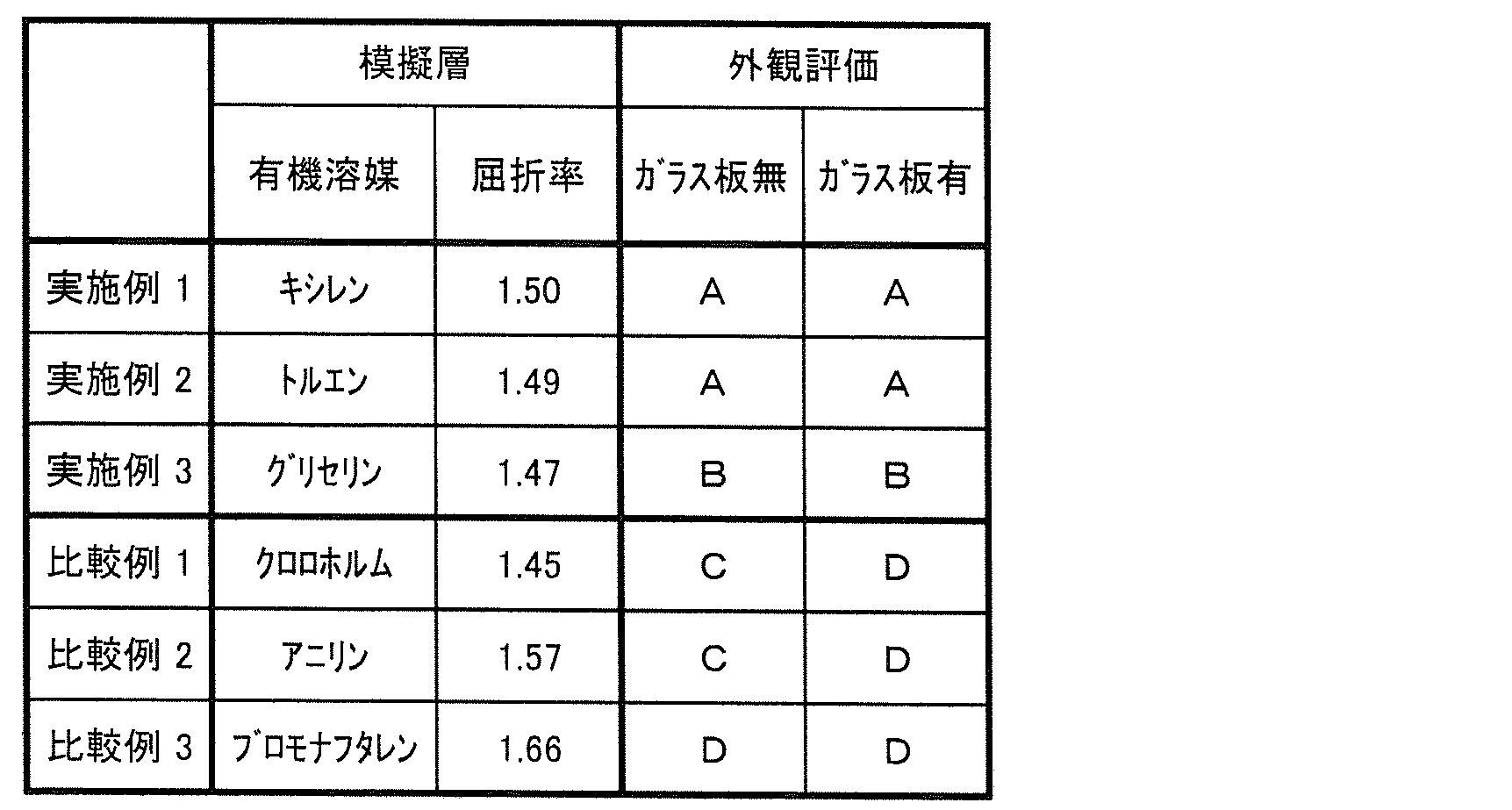
- An organic solvent layer coated with xylene (refractive index 1.50) is provided as a simulated layer of an adhesive layer made of a cured product of an active energy ray-curable adhesive on the surface of a polarizer having surface irregularities, and further A protective film B having a thickness of 25 ⁇ m (“KC2UAW” manufactured by Konica Minolta Co., Ltd.) is laminated on the simulated layer, and the protective film A / adhesive layer / polarizer / simulated layer / protective film B Thus, a simulated polarizing plate with a double-sided protective film was obtained.
- KC2UAW manufactured by Konica Minolta Co., Ltd.
- Examples 2 to 3 Comparative Examples 1 to 3> A simulated polarizing plate with a double-sided protective film was produced in the same manner as in Example 1 except that the type of organic solvent (and hence the refractive index) of the simulated layer was changed as shown in Table 1 below.
- A Skin defects and tea streaks are not visible at all.
- B Slightly poor skin or brown streaks can be visually recognized, but at a level that does not cause any practical problems.
- C Skin defects or tea streaks are clearly visible than B, D: Skin defects or brown stripes are noticeable visually.
- Example 4 A polarizing laminate film composed of a base film / polarizer was obtained according to (1) to (4) of Example 1. Thereafter, a protective film A made of triacetyl cellulose having a thickness of 25 ⁇ m (“KC2UAW” manufactured by Konica Minolta Co., Ltd.) was prepared, and an ultraviolet curable adhesive (“Optodyne UV3200” manufactured by Daikin Industries, Ltd.) The refractive index after curing: 1.51) was applied using a small-diameter gravure coater so that the thickness after curing was about 1.0 ⁇ m, and this was applied to the polarizing laminated film using a bonding roll. Bonded to the polarizer surface.
- KC2UAW triacetyl cellulose having a thickness of 25 ⁇ m
- an ultraviolet curable adhesive (“Optodyne UV3200” manufactured by Daikin Industries, Ltd.)
- the refractive index after curing: 1.51 was applied using a small-diameter gravure
- the adhesive layer is cured by irradiating ultraviolet rays from the base film side with an integrated light amount of 200 mJ / cm 2 using a high-pressure mercury lamp, and the protective film A / adhesive layer / polarizer / base film A laminated film having a layer structure was obtained.
- the base film was peeled and removed from the obtained bonding film to obtain a polarizing plate with a single-side protective film having a layer structure of protective film A / adhesive layer / polarizer.
- the thickness of the polarizer was 5.4 ⁇ m.
- Example 5 A polarizing plate with a single-sided protective film was prepared in the same manner as in Example 4 except that “Optodyne UV3100” (refractive index after curing: 1.49) manufactured by Daikin Industries, Ltd. was used as the ultraviolet curable adhesive. did.
- Example 6 Same as Example 4 except that “Optodyne UV2100” (refractive index before curing: 1.45, refractive index after curing: 1.48) manufactured by Daikin Industries, Ltd. was used as the ultraviolet curable adhesive.
- the polarizing plate with a single-sided protective film was produced by the method.
- the same ultraviolet curable adhesive as that used for bonding the protective film A and the polarizer is used for bonding the protective film A and the glass plate, and cured under the same conditions.
- an adhesive layer having a thickness after curing of about 1.0 ⁇ m was formed.
Landscapes
- Engineering & Computer Science (AREA)
- Physics & Mathematics (AREA)
- General Physics & Mathematics (AREA)
- General Engineering & Computer Science (AREA)
- Theoretical Computer Science (AREA)
- Optics & Photonics (AREA)
- Human Computer Interaction (AREA)
- Polarising Elements (AREA)
- Liquid Crystal (AREA)
Abstract
Description
[1]偏光子と、その一方の面に第1接着剤層を介して積層される第1保護フィルムとを含み、
第1接着剤層は、活性エネルギー線硬化性接着剤の硬化物からなる屈折率1.47以上1.57未満の層であり、かつ、偏光子の前記一方の面に接して積層されている、偏光板。
[3]前記第1保護フィルムは、その厚みが30μm以下である、[1]又は[2]に記載の偏光板。
(1)偏光板の層構成
図1は、本発明に係る偏光板の層構成の一例を示す概略断面図である。図1に示される偏光板1のように本発明の偏光板は、偏光子5と、その一方の面に第1接着剤層15を介して積層される第1保護フィルム10とを備える片面保護フィルム付偏光板であることができる。第1接着剤層15は、活性エネルギー線硬化性接着剤の硬化物からなる層であり、図1に示されるように、偏光子5の上記一方の面に接して偏光子5上に積層される。
偏光子5は、一軸延伸されたポリビニルアルコール系樹脂層(又はフィルム)に二色性色素を吸着配向させたものであることができる。偏光子5の厚みは例えば30μm以下、さらには20μm以下であることができるが、とりわけモバイル機器用の偏光板においては、偏光板の薄型化の観点から10μm以下であることが好ましく、8μm以下であることがより好ましい。偏光子5の厚みは通常、2μm以上である。
ケン化度(モル%)=100×(水酸基の数)÷(水酸基の数+酢酸基の数)
で定義される。ケン化度は、JIS K 6726(1994)に準拠して求めることができる。ケン化度が高いほど、水酸基の割合が高いことを示しており、従って結晶化を阻害する酢酸基の割合が低いことを示している。
第1保護フィルム10は、透光性を有する(好ましくは光学的に透明な)熱可塑性樹脂、例えば、鎖状ポリオレフィン系樹脂(ポリプロピレン系樹脂等)、環状ポリオレフィン系樹脂(ノルボルネン系樹脂等)のようなポリオレフィン系樹脂;セルローストリアセテート、セルロースジアセテートのようなセルロースエステル系樹脂;ポリエステル系樹脂;ポリカーボネート系樹脂;(メタ)アクリル系樹脂;ポリスチレン系樹脂;又はこれらの混合物、共重合物等からなるフィルムであることができる。中でも本発明において好適に用いられる第1保護フィルム10は、水系接着剤では接着が難しい透湿性の低い保護フィルム、例えばポリオレフィン系樹脂、ポリエステル系樹脂、(メタ)アクリル系樹脂、ポリスチレン系樹脂等からなる保護フィルムである。
第1接着剤層15は、偏光子5の一方の面に第1保護フィルム10を接着固定するための層であり、偏光子5に直接接合されるよう偏光子5の上記一方の面に接して積層される。第1接着剤層15は通常、第1保護フィルム10の貼合面(偏光子5側の面)にも接している。
図2に示される両面保護フィルム付偏光板2が有する第2保護フィルム20は、第1保護フィルム10と同様、上で例示した熱可塑性樹脂からなるフィルムであることができ、位相差フィルム、輝度向上フィルムのような光学機能を併せ持つ保護フィルムであってもよい。第2保護フィルム20が有し得る表面処理層及びフィルムの厚み等については、第1保護フィルム10について述べた上の記載が引用される。第1保護フィルム10と第2保護フィルム20とは、互いに同種の樹脂からなる保護フィルムであってもよいし、異種の樹脂からなる保護フィルムであってもよい。両面保護フィルム付偏光板2が液晶表示装置のような画像表示装置に組み込まれるとき、第2保護フィルム20は、偏光子5よりも画像表示素子側に配置される。
第2接着剤層25は、偏光子5の他方の面に第2保護フィルム20を接着固定するための層であり、第1接着剤層15と同様、偏光子5に直接接合されるよう偏光子5の上記他方の面に接して積層されるのが通常である。また、第2接着剤層25は通常、第2保護フィルム20の貼合面(偏光子5側の面)にも接している。
図3に示される偏光板3が備える透光性部材30は、例えば、画像表示装置の表面を保護するための透光性の板材やシート材、画像表示装置がタッチパネル装置である場合における、タッチ位置情報を検知するためのタッチ入力素子であることができる。透光性の板材又はシート材は、光学的に透明なものであることが好ましく、例えばガラス板や熱可塑性樹脂シート等を挙げることができる。タッチ入力素子も、通常はガラス板や熱可塑性樹脂シート等で構成される。
図1及び図3に示される片面保護フィルム付偏光板1,3における偏光子5上、又は図2に示される両面保護フィルム付偏光板2における第2保護フィルム20上に、偏光板を他の部材(例えば液晶表示装置に適用する場合における液晶セル)に貼合するための粘着剤層を積層してもよい。粘着剤層を形成する粘着剤は通常、(メタ)アクリル系樹脂、スチレン系樹脂、シリコーン系樹脂等をベースポリマーとし、そこに、イソシアネート化合物、エポキシ化合物、アジリジン化合物のような架橋剤を加えた粘着剤組成物からなる。さらに微粒子を含有して光散乱性を示す粘着剤層とすることもできる。粘着剤層の厚みは通常、1~40μmであり、好ましくは3~25μmである。
本発明に係る偏光板は、その保護フィルム10,20や偏光子5上に積層される他の光学層をさらに含むことができる。他の光学層としては、ある種の偏光光を透過し、それと逆の性質を示す偏光光を反射する反射型偏光フィルム;表面に凹凸形状を有する防眩機能付フィルム;表面反射防止機能付フィルム;表面に反射機能を有する反射フィルム;反射機能と透過機能とを併せ持つ半透過反射フィルム;視野角補償フィルム等が挙げられる。
本発明の偏光板は、薄膜の偏光子5を容易に得ることができ、製造工程中におけるフィルムの取扱性も良好であることから、図4に示される方法によって製造されることが好ましい。図4に示される製造方法は、下記工程:
(1)基材フィルムの少なくとも一方の面にポリビニルアルコール系樹脂を含有する塗工液を塗工した後、乾燥させることによりポリビニルアルコール系樹脂層を形成して積層フィルムを得る樹脂層形成工程S10、
(2)積層フィルムを延伸して延伸フィルムを得る延伸工程S20、
(3)延伸フィルムのポリビニルアルコール系樹脂層を二色性色素で染色して偏光子を形成することにより偏光性積層フィルムを得る染色工程S30、
(4)偏光性積層フィルムの偏光子上に保護フィルムを貼合して貼合フィルムを得る第1貼合工程S40、
(5)貼合フィルムから基材フィルムを剥離除去して片面保護フィルム付偏光板を得る剥離工程S50、
をこの順で含む。
(6)片面保護フィルム付偏光板の偏光子面に保護フィルムを貼合する第2貼合工程S60、
を含む。
図5を参照して本工程は、基材フィルム40の少なくとも一方の面にポリビニルアルコール系樹脂層6を形成して積層フィルム100を得る工程である。このポリビニルアルコール系樹脂層6は、延伸工程S20及び染色工程S30を経て偏光子5となる層である。ポリビニルアルコール系樹脂層6は、ポリビニルアルコール系樹脂を含有する塗工液を基材フィルム40の片面又は両面に塗工し、乾燥させることにより形成することができる。このような塗工によりポリビニルアルコール系樹脂層を形成する方法は、薄膜の偏光子5を得やすい点で有利である。
図6を参照して本工程は、基材フィルム40及びポリビニルアルコール系樹脂層6からなる積層フィルム100を延伸して、延伸された基材フィルム40’及びポリビニルアルコール系樹脂層6’からなる延伸フィルム200を得る工程である。延伸処理は通常、一軸延伸である。
図7を参照して本工程は、延伸フィルム200のポリビニルアルコール系樹脂層6’を二色性色素で染色してこれを吸着配向させ、偏光子5とする工程である。本工程を経て基材フィルム40’の片面又は両面に偏光子5が積層された偏光性積層フィルム300が得られる。
図8を参照して本工程は、偏光性積層フィルム300の偏光子5上、すなわち、偏光子5の基材フィルム40’側とは反対側の面に接着剤層を介して保護フィルムを貼合することで貼合フィルム400を得る工程である。図8には第1接着剤層15を介して第1保護フィルム10を貼合する例を示しているが、両面保護フィルム付偏光板2を製造する場合には、第2接着剤層25を介して第2保護フィルム20を貼合するようにしてもよい。第1接着剤層15や第2接着剤層25を形成する接着剤については上述のとおりである。
本工程は、貼合フィルム400から基材フィルム40’を剥離除去する工程である。この工程を経て、図1と同様の片面保護フィルム付偏光板が得られるが、目的とする偏光板が片面保護フィルム付偏光板である場合には、第1貼合工程S40において第1保護フィルム10が貼合される。偏光性積層フィルム300が基材フィルム40’の両面に偏光子5を有し、これら両方の偏光子5に保護フィルムを貼合した場合には、この剥離工程S50により、1枚の偏光性積層フィルム300から2枚の片面保護フィルム付偏光板が得られる。
本工程は、片面保護フィルム付偏光板の偏光子5上、すなわち第1貼合工程S40にて貼合した保護フィルムとは反対側の面に、さらに保護フィルムを貼合し、図2に示される構成の両面保護フィルム付偏光板2を得る工程である。第1貼合工程S40にて第1保護フィルム10が貼合される場合には、本工程にて第2保護フィルム20が貼合され、第1貼合工程S40にて第2保護フィルム20が貼合される場合には、本工程にて第1保護フィルム10が貼合される。第2接着剤層25を介した第2保護フィルム20の貼合は、第1保護フィルム10の貼合と同様にして行うことができる。
(1)プライマー層形成工程
ポリビニルアルコール粉末(日本合成化学工業(株)製の「Z-200」、平均重合度1100、ケン化度99.5モル%)を95℃の熱水に溶解し、濃度3重量%のポリビニルアルコール水溶液を調製した。得られた水溶液に架橋剤(田岡化学工業(株)製の「スミレーズレジン650」)をポリビニルアルコール粉末6重量部に対して5重量部の割合で混合して、プライマー層形成用塗工液を得た。
ポリビニルアルコール粉末((株)クラレ製の「PVA124」、平均重合度2400、ケン化度98.0~99.0モル%)を95℃の熱水に溶解し、濃度8重量%のポリビニルアルコール水溶液を調製し、これをポリビニルアルコール系樹脂層形成用塗工液とした。
上記(2)で作製した積層フィルムに対し、フローティングの縦一軸延伸装置を用いて160℃で5.3倍の自由端一軸延伸を実施し、延伸フィルムを得た。延伸後のポリビニルアルコール系樹脂層の厚みは5.0μmであった。
上記(3)で作製した延伸フィルムを、ヨウ素とヨウ化カリウムとを含む30℃の染色水溶液(水100重量部あたりヨウ素を0.6重量部、ヨウ化カリウムを10重量部含む)に約180秒間浸漬してポリビニルアルコール系樹脂層の染色処理を行った後、10℃の純水で余分な染色水溶液を洗い流した。
トリアセチルセルロースからなる厚み25μmの保護フィルムA(コニカミノルタ(株)製の「KC2UAW」)を用意し、その片面に紫外線硬化性接着剤を硬化後の厚みが1.0μm程度となるように小径グラビアコーターを用いて塗工した後、これを、貼合ロールを用いて上記(4)で作製した偏光性積層フィルムの偏光子面に貼合した。その後、高圧水銀ランプを用いて、基材フィルム側から200mJ/cm2の積算光量で紫外線を照射することにより接着剤層を硬化させ、保護フィルムA/接着剤層/偏光子/基材フィルムの層構成からなる貼合フィルムを得た(第1貼合工程)。
模擬層の有機溶媒の種類(従って屈折率)を下記の表1のとおりに変更したこと以外は実施例1と同様にして、模擬的な両面保護フィルム付偏光板を作製した。
(1)肌不良及び茶スジの視認抑制効果(ガラス板無)
蛍光灯下で、得られた両面保護フィルム付偏光板の偏光子表面(保護フィルムAが貼合されている面とは反対側の面)を、保護フィルムB越しに目視で観察し、下記の評価基準に従って、実際には存在する肌不良及び茶スジがどの程度視認できなくなっているかを評価した。結果を表1に示す。なお、上記の実施例1~3及び比較例1~3では活性エネルギー線硬化性接着剤の硬化物からなる接着剤層の代わりに、その模擬層として有機溶媒層を用いているが、偏光子表面にある肌不良及び茶スジが保護フィルム越しに視認されるのは、もっぱら偏光子とその上に接合される層との界面での界面反射に基づいているため、模擬層を用いた試験によっても、本発明の効果を十分に確認することができる。
B:わずかに肌不良又は茶スジを視認できるが、実用上問題のないレベルである、
C:肌不良又は茶スジがBよりも明確に視認される、
D:肌不良又は茶スジが顕著に視認される。
各実施例及び比較例で得られた両面保護フィルム付偏光板の保護フィルムBの上に、各実施例及び比較例で用いたものと同じ有機溶媒からなる有機溶媒層を設け、さらにその上にガラス板を積層した。この状態で、保護フィルムB、有機溶媒層及びガラス板越しに目視で観察し、上記の評価基準に従い上記(1)と同様にして、肌不良及び茶スジがどの程度視認できなくなっているかを評価した。結果を表1に示す。
実施例1の(1)~(4)に従って基材フィルム/偏光子からなる偏光性積層フィルムを得た。その後、トリアセチルセルロースからなる厚み25μmの保護フィルムA(コニカミノルタ(株)製の「KC2UAW」)を用意し、その片面に紫外線硬化性接着剤(ダイキン工業(株)製の「オプトダインUV3200」、硬化後の屈折率:1.51)を硬化後の厚みが1.0μm程度となるように小径グラビアコーターを用いて塗工した後、これを、貼合ロールを用いて上記偏光性積層フィルムの偏光子面に貼合した。その後、高圧水銀ランプを用いて、基材フィルム側から200mJ/cm2の積算光量で紫外線を照射することにより接着剤層を硬化させ、保護フィルムA/接着剤層/偏光子/基材フィルムの層構成からなる貼合フィルムを得た。
紫外線硬化性接着剤として、ダイキン工業(株)製の「オプトダインUV3100」(硬化後の屈折率:1.49)を用いたこと以外は実施例4と同じ方法で片面保護フィルム付偏光板を作製した。
紫外線硬化性接着剤として、ダイキン工業(株)製の「オプトダインUV2100」(硬化前の屈折率:1.45、硬化後の屈折率:1.48)を用いたこと以外は実施例4と同じ方法で片面保護フィルム付偏光板を作製した。
紫外線硬化性接着剤として、ダイキン工業(株)製の「オプトダインUV1000」(硬化後の屈折率:1.45)を用いたこと以外は実施例4と同じ方法で片面保護フィルム付偏光板を作製した。

Claims (6)
- 偏光子と、その一方の面に第1接着剤層を介して積層される第1保護フィルムとを含み、
第1接着剤層は、活性エネルギー線硬化性接着剤の硬化物からなる屈折率1.47以上1.57未満の層であり、かつ、偏光子の前記一方の面に接して積層されている、偏光板。 - 前記偏光子は、その厚みが10μm以下である、請求項1に記載の偏光板。
- 前記第1保護フィルムは、その厚みが30μm以下である、請求項1又は2に記載の偏光板。
- 前記偏光子の他方の面に第2接着剤層を介して積層される第2保護フィルムをさらに含む、請求項1~3のいずれか1項に記載の偏光板。
- 前記第1保護フィルムの外面に第3接着剤層を介して積層される透光性部材をさらに含む、請求項1~4のいずれか1項に記載の偏光板。
- 前記透光性部材がタッチ入力素子である、請求項5に記載の偏光板。
Priority Applications (3)
| Application Number | Priority Date | Filing Date | Title |
|---|---|---|---|
| CN201580036842.5A CN107027324B (zh) | 2014-07-10 | 2015-06-11 | 偏振板 |
| JP2015534306A JPWO2016006384A1 (ja) | 2014-07-10 | 2015-06-11 | 偏光板 |
| KR1020177001528A KR20170029518A (ko) | 2014-07-10 | 2015-06-11 | 편광판 |
Applications Claiming Priority (2)
| Application Number | Priority Date | Filing Date | Title |
|---|---|---|---|
| JP2014-142216 | 2014-07-10 | ||
| JP2014142216 | 2014-07-10 |
Publications (1)
| Publication Number | Publication Date |
|---|---|
| WO2016006384A1 true WO2016006384A1 (ja) | 2016-01-14 |
Family
ID=55064026
Family Applications (1)
| Application Number | Title | Priority Date | Filing Date |
|---|---|---|---|
| PCT/JP2015/066894 WO2016006384A1 (ja) | 2014-07-10 | 2015-06-11 | 偏光板 |
Country Status (5)
| Country | Link |
|---|---|
| JP (1) | JPWO2016006384A1 (ja) |
| KR (1) | KR20170029518A (ja) |
| CN (1) | CN107027324B (ja) |
| TW (1) | TWI654451B (ja) |
| WO (1) | WO2016006384A1 (ja) |
Cited By (8)
| Publication number | Priority date | Publication date | Assignee | Title |
|---|---|---|---|---|
| WO2017199632A1 (ja) * | 2016-05-16 | 2017-11-23 | 住友化学株式会社 | 偏光板 |
| JP2020052365A (ja) * | 2018-09-28 | 2020-04-02 | 住友化学株式会社 | 偏光板複合体、及び画像表示装置 |
| JP2020126270A (ja) * | 2020-05-01 | 2020-08-20 | 住友化学株式会社 | 偏光板複合体、及び画像表示装置 |
| JP2021039274A (ja) * | 2019-09-04 | 2021-03-11 | 日東電工株式会社 | 積層光学フィルムおよび画像表示装置 |
| JP2021039265A (ja) * | 2019-09-04 | 2021-03-11 | 日東電工株式会社 | 積層光学フィルムおよび画像表示装置 |
| JP2021039264A (ja) * | 2019-09-04 | 2021-03-11 | 日東電工株式会社 | 積層光学フィルムの製造方法 |
| JP2021039275A (ja) * | 2019-09-04 | 2021-03-11 | 日東電工株式会社 | 積層光学フィルムおよび画像表示装置 |
| WO2021176989A1 (ja) * | 2020-03-05 | 2021-09-10 | 住友化学株式会社 | 光学積層体及び表示装置 |
Families Citing this family (1)
| Publication number | Priority date | Publication date | Assignee | Title |
|---|---|---|---|---|
| JP2018092083A (ja) * | 2016-12-07 | 2018-06-14 | 住友化学株式会社 | 偏光板および液晶表示装置 |
Citations (3)
| Publication number | Priority date | Publication date | Assignee | Title |
|---|---|---|---|---|
| JP2012203108A (ja) * | 2011-03-24 | 2012-10-22 | Sumitomo Chemical Co Ltd | 偏光板の製造方法 |
| JP2013125077A (ja) * | 2011-12-13 | 2013-06-24 | Nitto Denko Corp | 偏光板用接着剤、偏光板、その製造方法、光学フィルム及び画像表示装置 |
| JP2014096241A (ja) * | 2012-11-08 | 2014-05-22 | Daicel Corp | 透明導電性シート及びタッチパネル |
Family Cites Families (6)
| Publication number | Priority date | Publication date | Assignee | Title |
|---|---|---|---|---|
| JP4306270B2 (ja) | 2003-02-12 | 2009-07-29 | 住友化学株式会社 | 偏光板、その製造法、光学部材及び液晶表示装置 |
| CN101568862A (zh) * | 2006-12-27 | 2009-10-28 | 郡是株式会社 | 偏振片保护膜、偏振片和电阻膜式触摸屏 |
| CN100517001C (zh) * | 2007-09-30 | 2009-07-22 | 京东方科技集团股份有限公司 | 显示装置的光学有机膜结构及显示装置 |
| CN104212386B (zh) | 2010-03-05 | 2017-01-11 | 日东电工株式会社 | 偏振板用胶粘剂、偏振板及其制造方法、光学膜、以及图像显示装置 |
| JP5756313B2 (ja) | 2011-03-25 | 2015-07-29 | 住友化学株式会社 | 偏光板の製造方法 |
| JP5988649B2 (ja) | 2012-03-29 | 2016-09-07 | 住友化学株式会社 | 偏光板の製造方法 |
-
2015
- 2015-06-11 WO PCT/JP2015/066894 patent/WO2016006384A1/ja active Application Filing
- 2015-06-11 KR KR1020177001528A patent/KR20170029518A/ko not_active IP Right Cessation
- 2015-06-11 JP JP2015534306A patent/JPWO2016006384A1/ja active Pending
- 2015-06-11 CN CN201580036842.5A patent/CN107027324B/zh active Active
- 2015-06-17 TW TW104119524A patent/TWI654451B/zh active
Patent Citations (3)
| Publication number | Priority date | Publication date | Assignee | Title |
|---|---|---|---|---|
| JP2012203108A (ja) * | 2011-03-24 | 2012-10-22 | Sumitomo Chemical Co Ltd | 偏光板の製造方法 |
| JP2013125077A (ja) * | 2011-12-13 | 2013-06-24 | Nitto Denko Corp | 偏光板用接着剤、偏光板、その製造方法、光学フィルム及び画像表示装置 |
| JP2014096241A (ja) * | 2012-11-08 | 2014-05-22 | Daicel Corp | 透明導電性シート及びタッチパネル |
Cited By (12)
| Publication number | Priority date | Publication date | Assignee | Title |
|---|---|---|---|---|
| WO2017199632A1 (ja) * | 2016-05-16 | 2017-11-23 | 住友化学株式会社 | 偏光板 |
| CN109154688A (zh) * | 2016-05-16 | 2019-01-04 | 住友化学株式会社 | 偏振板 |
| TWI722177B (zh) * | 2016-05-16 | 2021-03-21 | 日商住友化學股份有限公司 | 偏光板 |
| CN109154688B (zh) * | 2016-05-16 | 2021-03-23 | 住友化学株式会社 | 偏振板 |
| JP2020052365A (ja) * | 2018-09-28 | 2020-04-02 | 住友化学株式会社 | 偏光板複合体、及び画像表示装置 |
| JP2021039274A (ja) * | 2019-09-04 | 2021-03-11 | 日東電工株式会社 | 積層光学フィルムおよび画像表示装置 |
| JP2021039265A (ja) * | 2019-09-04 | 2021-03-11 | 日東電工株式会社 | 積層光学フィルムおよび画像表示装置 |
| JP2021039264A (ja) * | 2019-09-04 | 2021-03-11 | 日東電工株式会社 | 積層光学フィルムの製造方法 |
| JP2021039275A (ja) * | 2019-09-04 | 2021-03-11 | 日東電工株式会社 | 積層光学フィルムおよび画像表示装置 |
| JP7417386B2 (ja) | 2019-09-04 | 2024-01-18 | 日東電工株式会社 | 積層光学フィルムの製造方法 |
| WO2021176989A1 (ja) * | 2020-03-05 | 2021-09-10 | 住友化学株式会社 | 光学積層体及び表示装置 |
| JP2020126270A (ja) * | 2020-05-01 | 2020-08-20 | 住友化学株式会社 | 偏光板複合体、及び画像表示装置 |
Also Published As
| Publication number | Publication date |
|---|---|
| KR20170029518A (ko) | 2017-03-15 |
| CN107027324B (zh) | 2019-08-02 |
| CN107027324A (zh) | 2017-08-08 |
| TW201602659A (zh) | 2016-01-16 |
| TWI654451B (zh) | 2019-03-21 |
| JPWO2016006384A1 (ja) | 2017-04-27 |
Similar Documents
| Publication | Publication Date | Title |
|---|---|---|
| JP6249820B2 (ja) | 偏光板の製造方法及び偏光板 | |
| WO2016006384A1 (ja) | 偏光板 | |
| JP6894494B2 (ja) | 両面保護フィルム付偏光板の製造方法 | |
| JP2016153886A (ja) | 偏光フィルム及びそれを含む偏光板 | |
| JP6348291B2 (ja) | 偏光板及び表示装置 | |
| JP6231511B2 (ja) | 偏光フィルムの製造方法 | |
| JP6045622B2 (ja) | ポリビニルアルコール系樹脂フィルムの製造方法、偏光フィルム及び偏光板 | |
| JP2016148830A (ja) | 偏光フィルム及びそれを含む偏光板 | |
| JP6654448B2 (ja) | 積層偏光板の製造方法及び偏光板の製造方法 | |
| TW201618921A (zh) | 偏光性積層膜或偏光板的製造方法 | |
| JP6560509B2 (ja) | 偏光板の製造方法及び偏光性積層フィルムの保管方法 | |
| KR101942166B1 (ko) | 편광판의 제조 방법 | |
| JP6456710B2 (ja) | 積層偏光板の製造方法および偏光板の製造方法 | |
| KR102328404B1 (ko) | 편광판의 제조 방법 | |
| WO2017069184A1 (ja) | 延伸フィルムの製造方法及び偏光フィルムの製造方法 | |
| JP2018092156A (ja) | 偏光フィルム及び偏光性積層フィルムの製造方法 | |
| WO2016088585A1 (ja) | 偏光板の製造方法 | |
| JP2018010317A (ja) | ポリビニルアルコール系樹脂フィルムの製造方法及び偏光フィルムの製造方法 |
Legal Events
| Date | Code | Title | Description |
|---|---|---|---|
| ENP | Entry into the national phase |
Ref document number: 2015534306 Country of ref document: JP Kind code of ref document: A |
|
| 121 | Ep: the epo has been informed by wipo that ep was designated in this application |
Ref document number: 15819356 Country of ref document: EP Kind code of ref document: A1 |
|
| NENP | Non-entry into the national phase |
Ref country code: DE |
|
| ENP | Entry into the national phase |
Ref document number: 20177001528 Country of ref document: KR Kind code of ref document: A |
|
| WWE | Wipo information: entry into national phase |
Ref document number: 1020177001528 Country of ref document: KR |
|
| 122 | Ep: pct application non-entry in european phase |
Ref document number: 15819356 Country of ref document: EP Kind code of ref document: A1 |