WO2015199028A1 - NOxセンサ - Google Patents
NOxセンサ Download PDFInfo
- Publication number
- WO2015199028A1 WO2015199028A1 PCT/JP2015/067885 JP2015067885W WO2015199028A1 WO 2015199028 A1 WO2015199028 A1 WO 2015199028A1 JP 2015067885 W JP2015067885 W JP 2015067885W WO 2015199028 A1 WO2015199028 A1 WO 2015199028A1
- Authority
- WO
- WIPO (PCT)
- Prior art keywords
- electrode
- sensor
- solid electrolyte
- gas chamber
- nox
- Prior art date
- Legal status (The legal status is an assumption and is not a legal conclusion. Google has not performed a legal analysis and makes no representation as to the accuracy of the status listed.)
- Ceased
Links
Images





Classifications
-
- G—PHYSICS
- G01—MEASURING; TESTING
- G01N—INVESTIGATING OR ANALYSING MATERIALS BY DETERMINING THEIR CHEMICAL OR PHYSICAL PROPERTIES
- G01N27/00—Investigating or analysing materials by the use of electric, electrochemical, or magnetic means
- G01N27/26—Investigating or analysing materials by the use of electric, electrochemical, or magnetic means by investigating electrochemical variables; by using electrolysis or electrophoresis
- G01N27/416—Systems
Definitions
- the present disclosure relates to a NOx sensor having a solid electrolyte body having oxygen ion conductivity and a plurality of electrodes formed on the surface of the solid electrolyte body.
- a NOx sensor for measuring the concentration of NOx contained in automobile exhaust gas or the like, a measurement gas chamber into which exhaust gas (measurement gas) is introduced, a solid electrolyte body having oxygen ion conductivity, and the solid electrolyte body And a plurality of electrodes formed on the surface (see Patent Document 1 below).
- a pump cell and a sensor cell are formed by the solid electrolyte body and the electrode.
- the pump cell is a cell for reducing the oxygen concentration in the gas chamber to be measured.
- the sensor cell is a cell for measuring the concentration of NOx contained in the gas to be measured after the oxygen concentration is reduced by the pump cell.
- the pump cell decomposes O 2 molecules into oxygen ions at an electrode (pump electrode) constituting the pump cell, and discharges the oxygen ions from the gas chamber to be measured through the solid electrolyte body.
- the pump electrode does not decompose NOx. Therefore, a Pt—Au alloy having an active property with respect to O 2 but an inactive property with respect to NOx is used for the pump electrode. Since Au is inactive to NOx, if it contains Au, it becomes an electrode inactive to NOx as described above.
- the sensor cell decomposes NOx to generate oxygen ions at an electrode (sensor electrode) constituting the sensor cell, and discharges the oxygen ions from the gas chamber to be measured through the solid electrolyte body.
- the NOx concentration is measured by measuring the current flowing through the sensor cell.
- a Pt—Rh alloy active against NOx or Pt is used for the sensor electrode.
- a conductive paste to be used as a pump electrode or a sensor electrode is printed on the surface of the unfired solid electrolyte body, and combined with another ceramic material and fired. Since heat is applied to the pump electrode in this step, there is a known problem that Au contained in the pump electrode evaporates and adheres to the surface of the sensor electrode. Further, when the NOx sensor is used, since the solid electrolyte body is heated to the activation temperature using a heater, Au contained in the pump electrode is evaporated by the heat of the heater, and the surface of the sensor electrode It may adhere to. As described above, since Au is inactive with respect to NOx, if Au adheres to the surface of the sensor electrode, the ability of the sensor electrode to decompose NOx may be reduced.
- a porous layer made of a porous material may be formed on the surface of the pump electrode (see FIG. 11). If it does in this way, it can suppress that Au evaporates from a pump electrode by a porous layer. Therefore, it can suppress that Au adheres to the surface of a sensor electrode.
- a porous layer may be formed on the surface of the sensor electrode, thereby preventing the evaporated Au from adhering to the sensor electrode.
- the NOx sensor has a problem that there are few kinds of materials that can be used for the porous layer. That is, in order to completely cover the electrode with the porous layer, it is necessary to bring a part of the porous layer into contact with the solid electrolyte body (see FIG. 11). For this reason, it is necessary to form the porous layer using a material that adheres well to the solid electrolyte and the electrode.
- the electrode when the electrode is covered with a porous layer, it is difficult to manufacture a NOx sensor. That is, for example, when the sensor electrode is covered with a porous layer, the higher the porosity of the porous layer, the easier it is for the evaporated Au to pass through and for the Au to adhere to the sensor electrode. In addition, when the porosity of the porous layer is low, it is difficult for the evaporated Au to pass through and it is possible to prevent Au from adhering to the sensor electrode.
- the gas to be measured passes through the porous layer. Since it becomes difficult, the amount of current flowing through the sensor cell is reduced or the responsiveness is likely to be lowered. For this reason, it is necessary to adjust the porosity of the porous layer to an optimum range, and the production of the NOx sensor tends to be difficult. A similar problem occurs when the pump electrode is covered with a porous layer.
- the electrode when the electrode is covered with the porous layer, as described above, it is necessary to make the porous layer adhere well to both the electrode and the solid electrolyte body. Therefore, it is necessary to optimize the film quality of the porous layer so that the film can be satisfactorily adhered to these. Therefore, the manufacture of the NOx sensor tends to be difficult.
- the present disclosure has been made in view of such a background, and an object of the present disclosure is to provide a NOx sensor that can sufficiently suppress the decrease in activity of the sensor electrode with respect to NOx and can be easily manufactured.
- One aspect of the present disclosure includes a measurement gas chamber into which a measurement gas is introduced; A reference gas chamber into which the reference gas is introduced; A solid electrolyte body interposed between the gas chamber to be measured and the reference gas chamber and having oxygen ion conductivity; A plurality of electrodes formed on the main surface of the solid electrolyte body, The plurality of electrodes include a reference electrode formed on a main surface of the solid electrolyte body on the reference gas chamber side, and a pump electrode and a sensor formed on the main surface of the solid electrolyte body on the gas chamber side to be measured.
- the pump electrode is made of an alloy of Pt and Au
- the sensor electrode contains Pt
- the solid electrolyte body, the pump electrode, and the reference electrode form a pump cell that adjusts the oxygen concentration in the measured gas introduced into the measured gas chamber.
- the solid electrolyte body, the sensor electrode, and the A sensor cell for measuring the NOx concentration in the measurement gas is formed by the reference electrode, In the measurement gas chamber, Au that adsorbs Au atoms evaporated from the pump electrode at a position where none of the plurality of electrodes formed on the main surface of the solid electrolyte body on the measurement gas chamber side is covered.
- the NOx sensor is characterized in that an adsorption layer is formed.
- the Au adsorption layer is formed in the measured gas chamber. Therefore, even if Au evaporates from the pump electrode due to heat applied during manufacture or use of the NOx sensor, this Au can be adsorbed by the Au adsorption layer. Thereby, it is possible to suppress the evaporated Au from adhering to the surface of the sensor electrode, and it is possible to suppress a decrease in activity of the sensor electrode with respect to NOx.
- the Au adsorption layer is formed at a position where none of the plurality of electrodes is covered. Therefore, the choice of the material which comprises Au adsorption layer can be increased. That is, since the Au adsorption layer does not cover the electrode, the Au adsorption layer is not particularly required to be formed of a material having excellent adhesion to the electrode. Therefore, the choice of the material which forms Au adsorption layer can be increased, and it becomes possible to form Au adsorption layer with the material which was especially excellent in the adsorptivity of Au. Therefore, Au evaporated from the pump electrode can be effectively adsorbed, and the amount of Au attached to the sensor electrode can be reduced. Thereby, it is possible to sufficiently suppress the decrease in activity of the sensor electrode with respect to NOx.
- the Au adsorption layer is formed so as to cover the electrode, it is necessary to form the Au adsorption layer with a porous material, and it is necessary to adjust the porosity to an optimum range. That is, if the porosity of the Au adsorbing layer is too high, it becomes easier for Au to pass through when the NOx sensor is baked, and Au is likely to adhere to the sensor electrode. In addition, if the porosity is too low, the gas to be measured does not easily pass through the Au adsorption layer when the NOx sensor is used, which causes problems such as a decrease in responsiveness. Therefore, it is necessary to adjust the porosity of the Au adsorption layer to an optimum range.
- the Au adsorption layer is formed at a position where none of the plurality of electrodes is covered, it is not necessary to optimize the porosity. Further, as described above, it is not necessary to make the Au adsorbing layer adhere well to both the electrode and the solid electrolyte body. Therefore, the NOx sensor can be easily manufactured.
- the present invention it is possible to provide a NOx sensor that can sufficiently suppress the decrease in activity of the sensor electrode with respect to NOx and can be easily manufactured.
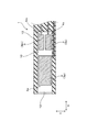
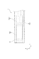
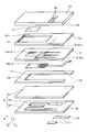
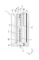
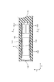
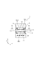
- FIG. 3 is a cross-sectional view of a NOx sensor in the first embodiment. II-II sectional drawing of FIG. III-III sectional view of FIG. The IV arrow line view of FIG. 1 is an exploded perspective view of a NOx sensor in Embodiment 1.
- FIG. FIG. 3 is a cross-sectional view of a NOx sensor in which a pump cell and a sensor cell are formed in separate solid electrolyte bodies in Example 1. The Au adhesion amount measurement result on the sensor cell surface in Experimental Example 1. Sectional drawing of the NOx sensor in Example 2.
- FIG. FIG. 11 is a cross-sectional view of the NOx sensor according to the third embodiment, which is a IX-IX cross-sectional view of FIG. XX sectional drawing of FIG. Sectional drawing of the NOx sensor in the comparative example 1.
- the NOx sensor can be an in-vehicle NOx sensor for measuring the NOx concentration contained in the exhaust gas of an automobile.
- the NOx sensor 1 of the present example includes a measured gas chamber 10, a reference gas chamber 11, a solid electrolyte body 2, and a plurality of electrodes 3 (3p, 3s, 3m, 3b). Is provided.
- a measurement gas g is introduced into the measurement gas chamber 10, and a reference gas such as the atmosphere is introduced into the reference gas chamber 11.
- the solid electrolyte body 2 is interposed between the measured gas chamber 10 and the reference gas chamber 11.
- the solid electrolyte body 2 has oxygen ion conductivity.
- the electrode 3 is formed on the main surfaces 21 and 22 of the solid electrolyte body 2.
- the plurality of electrodes 3 include a reference electrode 3b, a pump electrode 3p, and a sensor electrode 3s.
- the reference electrode 3 b is formed on the main surface 22 of the solid electrolyte body 2 on the reference gas chamber 11 side.
- the pump electrode 3p and the sensor electrode 3s are formed on the main surface 21 of the solid electrolyte body 2 on the measured gas chamber 10 side.
- the pump electrode 3p is made of an alloy of Pt and Au
- the sensor electrode 3s is made of an alloy of Pt and Rh or Pt.
- the solid electrolyte body 2, the pump electrode 3p, and the reference electrode 3b form a pump cell 4p that adjusts the oxygen concentration in the measurement gas g introduced into the measurement gas chamber 10.
- the solid electrolyte body 2, the sensor electrode 3s, and the reference electrode 3b form a sensor cell 4s that measures the NOx concentration in the gas to be measured.
- the Au atoms evaporated from the pump electrode 3p are adsorbed in a position where none of the plurality of electrodes 3 formed on the main surface 21 of the solid electrolyte body 2 on the measured gas chamber 10 side is covered.
- An Au adsorbing layer 5 is formed.
- the NOx sensor 1 of this example is a vehicle-mounted NOx sensor for measuring the concentration of NOx contained in automobile exhaust gas.
- the Au adsorption layer 5 of this example can contain, for example, a metal element selected from Pt, Pd, Ni, Rh, Ir, Ta, W, and Mo as a main component. Among these metal elements, it is preferable to use Pt with high Au adsorption efficiency.
- the “main component” means a component having the highest mass ratio.
- Au adsorption layer 5 of this embodiment may also be constituted by a porous ceramic material selected CeO 2, TiO 2, CZY, from Al 2 O 3, ZrO 2.
- the Au adsorption layer 5 of this example is formed at a position facing the pump electrode 3p in the thickness direction (Z direction) of the pump electrode 3p.
- the NOx sensor 1 of this example includes a sensor cell 4s in addition to the pump cell 4p and the sensor cell 4s.
- the sensor cell 4s includes a solid electrolyte body 2, a monitor electrode 3m, and a reference electrode 3b.
- the monitor electrode 3m is made of an alloy of Pt and Au.
- the monitor electrode 3m is formed on the main surface 21 of the solid electrolyte body 2 on the measured gas chamber 10 side.
- the concentration of O 2 slightly remaining in the measurement gas g is measured using the monitor cell 4m. That is, O 2 is reduced to oxygen ions at the monitor electrode 3m, and the oxygen ions are discharged to the reference gas chamber 11 side through the solid electrolyte body 2.
- the residual O 2 concentration is measured by measuring the value of the current flowing at this time.
- the total concentration of O 2 and NOx contained in the gas to be measured g whose O 2 concentration is reduced by the pump cell 4p is measured. That is, O 2 and NOx are decomposed at the sensor electrode 3s to generate oxygen ions.
- the total concentration of O 2 and NOx is measured by measuring the current value generated when the oxygen ions flow through the solid electrolyte body 2. Then, the NOx concentration is calculated by subtracting the O 2 concentration measured using the monitor cell 4m from the total concentration.
- the sensor electrode 3s Since the sensor electrode 3s is active for both O 2 and NOx, only the total concentration of these can be measured. Therefore, only the O 2 concentration is measured using the monitor cell 4m, and the NO x concentration can be accurately measured by subtracting the O 2 concentration from the total concentration.
- the NOx sensor 1 of this example includes a ceramic plate-like portion 13, a first spacer 14, a second spacer 15, a heater 6, and a diffusion resistance layer 12.
- a gas chamber 10 to be measured is formed by the first spacer 14, and a reference gas chamber 11 is formed by the second spacer 15.
- Each of these spacers 14 and 15 is made of ceramic.
- the diffusion resistance layer 12 is made of alumina or the like.
- the diffusion resistance layer 12 limits the amount of gas to be measured g introduced from the outside of the sensor into the gas chamber 10 to be measured.
- the plate-like portion 13 is formed with a connection terminal 16 that is electrically connected to the electrode 3.
- An Au adsorption layer 5 is formed on the main surface 130 (see FIG. 1) of the plate-like portion 13 on the measured gas chamber 10 side.
- the composition of the Au adsorption layer 5 of this example is the same as that of the reference electrode 3b.
- the solid electrolyte body 2 is made of zirconia, partially stabilized zirconia, or the like. As described above, a plurality of electrodes 3 (3p, 3s, 3m, 3b) are formed on the surface of the solid electrolyte body 2. As shown in FIGS. 2 and 5, the monitor electrode 3m and the sensor electrode 3s are arranged in the width direction (Y direction) orthogonal to both the longitudinal direction (X direction) of the solid electrolyte body 2 and the thickness direction (Z direction). Are next to each other. The monitor electrode 3m and the sensor electrode 3s are formed at positions adjacent to the pump electrode 3p in the X direction.
- the heater 6 includes two alumina sheets 61 and 63 and an electric heating section 62 interposed between the two alumina sheets 61 and 63.
- a heater terminal 17 electrically connected to the electric heating portion 62 is formed. It is configured to raise the temperature of the solid electrolyte body 2 to the activation temperature by causing a current to flow through the electric heating section 62 to generate heat.
- an unfired solid electrolyte body 2 is prepared, and a pump electrode 3p, a sensor electrode 3s, a monitor electrode 3m, and a reference electrode 3b are respectively formed on the surfaces 21 and 22 of the solid electrolyte body 2.
- a conductive paste is printed.
- an unfired plate-like portion 13, a first spacer 14, and a second spacer 15 are prepared.
- a paste that becomes the Au adsorption layer 5 is printed on the unfired plate-like portion 13.
- this paste is prepared by mixing Pt powder, which is a main component, and alumina powder at a predetermined ratio, and further, an organic binder such as acrylic resin, a plasticizer such as DBP and DOP, an organic solvent such as terpineol, and the like. Can be used.
- vias 18 for electrically connecting the electrodes 3 and the connection terminals 16 are formed in the spacers 14 and 15 and the plate-like portion 13. And the unbaked said plate-shaped part 13, the 1st spacer 14, the solid electrolyte body 2, and the 2nd spacer 15 are laminated
- a conductive paste to be the electric heating portion 62 is printed on one alumina sheet 63 of the two alumina sheets 61 and 63. Further, a paste to be used as the heater terminal 17 and the connection terminal 16 is printed on the surface of one alumina sheet 63. Vias 18 for electrical connection are formed in the alumina sheets 61 and 63. Then, the two alumina sheets 61 and 63 are laminated to form a heater laminate.
- the sensor laminate and the heater laminate are laminated and compressed in the Z direction while heating the whole. Thereby, the layers are brought into close contact with each other to form an unfired NOx sensor. Thereafter, the unfired NOx sensor is fired at a predetermined temperature.
- the firing temperature can be about 1400 to 1500 ° C., for example.
- the Au adsorption layer 5 is formed in the measured gas chamber 10. Therefore, even if Au evaporates from the pump electrode 3p due to the heat of firing the ceramic when the NOx sensor 1 is manufactured or the heat generated from the heater 6 when the NOx sensor 1 is used, this Au is adsorbed by the Au adsorption layer 5. be able to. Thereby, it can suppress that Au adheres to the surface of 3 s of sensor electrodes, and it becomes possible to suppress the activity fall with respect to NOx of 3 s of sensor electrodes.
- the Au adsorption layer 5 is formed at a position where none of the plurality of electrodes 3 (3p, 3m, 3s) is covered. Therefore, the choice of the material which comprises Au adsorption layer 5 can be increased. That is, since the Au adsorbing layer 5 does not cover the electrode 3, the Au adsorbing layer 5 is not particularly required to be formed of a material having excellent adhesion to the electrode 3. Therefore, the choice of the material which forms Au adsorption layer 5 can be increased, and it becomes possible to form Au adsorption layer 5 with the material which was excellent in Au adsorption property especially. Therefore, Au evaporated from the pump electrode 3p can be effectively adsorbed, and the amount of Au adhering to the sensor electrode 3s can be reduced. Thereby, it is possible to sufficiently suppress the decrease in activity of the sensor electrode 3s with respect to NOx.
- the Au adsorbing layer (Au adsorbing layer 5) is formed so as not to cover the electrode 3 as in this example, the adhesion to the electrode 3 is not necessarily excellent. Therefore, the choice of materials that can be used as the Au adsorption layer 5 can be expanded. Therefore, a material that is particularly excellent in the Au adsorption effect can be used as the Au adsorption layer 5. Therefore, the amount of Au adhering to the sensor electrode 3s can be reduced, and the decrease in activity of the sensor electrode 3s with respect to NOx can be sufficiently suppressed.
- the Au adsorbing layer (Au adsorbing layer 5) is formed at a position not covering the electrode 3 as in this example, the porosity of the Au adsorbing layer 5 is optimized. Since there is no need in particular, it becomes possible to manufacture a NOx sensor easily.
- the Au adsorption layer 5 of this example is formed at a position facing the pump electrode 3p in the Z direction. Therefore, the Au adsorption layer 5 can be provided in the vicinity of the pump electrode 3p. Therefore, Au evaporated from the pump electrode 3p can be immediately adsorbed, and Au can be prevented from moving to the sensor electrode 3s. Therefore, the amount of Au attached to the sensor electrode 3s can be reduced.
- the Au adsorption layer 5 can be formed of a material containing, for example, Pt, Pd, Ni, Rh, and Ir as main components. Since these metals have a face-centered cubic structure like Au, they easily adsorb Au.
- the Au adsorption layer 5 can also be formed of a material containing Ta, W, and Mo as main components. These metals have a relatively large adsorption energy. Therefore, Au can be effectively adsorbed by using these metals.
- the Au adsorption layer 5 preferably contains Pt as a main component. Since Pt is a noble metal element like Au, it has a high affinity with Au. Therefore, if the Au adsorption layer 5 is formed of a material containing Pt as a main component, it becomes possible to adsorb Au particularly effectively. Since Pt is also contained in the sensor electrode 3s, even if Pt evaporates from the Au adsorption layer 5 and adheres to the sensor electrode 3s, the characteristics of the sensor electrode 3s do not vary greatly.
- the Au adsorption layer 5 contains Pt as a main component and further contains alumina. If the Au adsorption layer 5 contains alumina, the Au adsorbing layer 5 is easily adhered to the plate-like portion 13. Therefore, problems such as peeling of the Au adsorbing layer 5 due to thermal stress or the like are less likely to occur.
- the porosity of the Au adsorption layer 5 is preferably 5 to 95%. In this case, the surface area of the Au adsorption layer 5 can be increased. Therefore, Au adsorption efficiency can be increased. When the porosity of the Au adsorption layer 5 is less than 5%, the efficiency of adsorbing Au is lowered. On the other hand, if the porosity exceeds 95%, the durability tends to decrease.
- the Au adsorbing layer 5 preferably has the same composition as the reference electrode 3b.
- the Au adsorption layer 5 and the reference electrode 3b can be formed using the same conductive paste. Therefore, the types of conductive paste to be prepared can be reduced in the NOx sensor 1 manufacturing factory. Therefore, it becomes easy to reduce the manufacturing cost of the NOx sensor 1.
- the Au adsorption layer 5 may be constituted by a porous ceramic material selected CeO 2, TiO 2, CZY, from Al 2 O 3, ZrO 2. Since these materials are porous, they have a large surface area. Therefore, it is excellent in the adsorptivity of Au.
- FIGS. 1 and 2 three types of cells 4 (pump cell 4p, sensor cell 4s, monitor cell 4m) are formed in one solid electrolyte body 2, but the present invention is not limited to this. It is not a thing. That is, as shown in FIG. 6, two solid electrolyte bodies 2a and 2b are used to form a pump cell 4p in one first solid electrolyte body 2a, and a sensor cell 4s and a monitor cell 4m are formed in the other second solid electrolyte body 2b. May be formed. Specifically, the solid electrolyte bodies 2a and 2b may have a main surface facing the gas chamber 10 to be measured, and opposite main surfaces may face different spaces (reference gas chambers 11a and 11b). .
- the pump electrode 3p is formed on the surface of the first solid electrolyte body 2a on the measured gas chamber 10 side, and the sensor electrode 3s is formed on the surface of the second solid electrolyte body 2b on the measured gas chamber 10 side. Also good.
- the Au adsorption layer 5 may be formed at a position facing the pump electrode 3p in the Z direction. In this case, the Au adsorption layer 5 is formed on the surface of the other solid electrolyte body 2b.
- the obtained NOx sensor was disassembled, and the amount of Au deposited on the surface of the sensor electrode 3s was investigated using XPS (X-ray photoelectron spectroscopy). The result is shown in FIG.
- the NOx sensor 1 having the Au adsorption layer 5 has only a small amount of Au attached to the sensor electrode 3s. Further, it can be seen that the NOx sensor in which the Au adsorption layer 5 is not formed has 20% of Au attached to the sensor electrode 3s.
- the NOx sensor 1 in which the Au adsorption layer 5 is formed has a smaller amount of Au adhering to the sensor electrode 3s than the NOx sensor in which the Au adsorption layer 5 is not formed. It can be seen that the decrease in activity can be suppressed.
- Example 2 In the following Examples 2 and 3, the same reference numerals used in the drawings as those used in Example 1 represent the same constituent elements as those in Example 1 unless otherwise indicated.
- the position of the Au adsorption layer 5 is changed. As shown in FIG. 8, in this example, the Au adsorption layer 5 is formed on the main surface 21 of the solid electrolyte body 2 on the measured gas chamber 10 side. The Au adsorption layer 5 is formed between the sensor electrode 3s and the monitor electrode 3m, and the pump electrode 3p. By forming the Au adsorption layer 5 at this position, the electrode 3 (3p, 3m, 3s) is prevented from being covered with the Au adsorption layer 5. In addition, the configuration and operational effects are the same as those of the first embodiment.
- Example 3 the position of the Au adsorption layer 5 is changed.
- the Au adsorption layer 5 is formed on the side surfaces 141 and 142 of the first spacer 14. That is, the Au adsorbing layer 5 may be formed on the side wall erected in the thickness direction among the surfaces on which the measurement gas chamber 10 is formed.
- the electrode 3 (3p, 3m, 3s) is prevented from being covered with the Au adsorption layer 5.
- the configuration and operational effects are the same as those of the first embodiment.
Landscapes
- Chemical & Material Sciences (AREA)
- Life Sciences & Earth Sciences (AREA)
- Health & Medical Sciences (AREA)
- Physics & Mathematics (AREA)
- Chemical Kinetics & Catalysis (AREA)
- Electrochemistry (AREA)
- Molecular Biology (AREA)
- Analytical Chemistry (AREA)
- Biochemistry (AREA)
- General Health & Medical Sciences (AREA)
- General Physics & Mathematics (AREA)
- Immunology (AREA)
- Pathology (AREA)
- Measuring Oxygen Concentration In Cells (AREA)
Abstract
センサ電極の、NOxに対する活性低下を充分に抑制でき、容易に製造できるNOxセンサを提供する。被測定ガス室(10)と、基準ガス室(11)と、固体電解質体(2)と、複数の電極(3)とを備える。複数の電極(3)には、基準電極(3b)と、ポンプ電極(3p)と、センサ電極(3s)とがある。ポンプ電極(3p)及びセンサ電極(3s)は、固体電解質体(2)の被測定ガス室(10)側の主面(21)に形成されている。ポンプ電極(3p)はPtとAuとの合金からなり、センサ電極(3s)はPtとRhとの合金またはPtからなる。被測定ガス室(10)内には、固体電解質体(2)の被測定ガス室(10)側の主面(21)に形成された複数の電極(3)をいずれも被覆しない位置に、ポンプ電極(3p)から蒸散したAu原子を吸着するAu吸着層(5)が形成されている。
Description
本出願は、2014年6月23日に出願された日本出願番号2014-128012号に基づくもので、ここにその記載内容を援用する。
本開示は、酸素イオン伝導性を有する固体電解質体と、該固体電解質体の表面に形成された複数の電極とを有するNOxセンサに関する。
自動車の排気ガス等に含まれるNOxの濃度を測定するNOxセンサとして、排気ガス(被測定ガス)が導入される被測定ガス室と、酸素イオン伝導性を有する固体電解質体と、該固体電解質体の表面に形成された複数の電極とを備えるものが知られている(下記特許文献1参照)。このNOxセンサでは、固体電解質体と上記電極とによって、ポンプセル及びセンサセルを形成してある。ポンプセルは、被測定ガス室内の酸素濃度を低減させるためのセルである。また、センサセルは、ポンプセルによって酸素濃度を低減させた後の被測定ガスに含まれるNOxの濃度を測定するためのセルである。
ポンプセルは、該ポンプセルを構成する電極(ポンプ電極)において、O2分子を分解して酸素イオンにし、この酸素イオンを、固体電解質体を通して被測定ガス室から排出する。ポンプ電極では、NOxは分解させない。そのためポンプ電極には、O2に対して活性であるがNOxに対して不活性な性質を有する、Pt-Au合金が用いられる。AuはNOxに不活性であるため、Auを含有すると、上述のようにNOxに不活性な電極となる。
また、センサセルは、該センサセルを構成する電極(センサ電極)において、NOxを分解して酸素イオンを発生させ、この酸素イオンを、固体電解質体を通して被測定ガス室から排出する。このときにセンサセルに流れる電流を測定することにより、NOx濃度を測定するよう構成されている。センサ電極は、NOxに対して活性なPt-Rh合金や、Ptが用いられる。
NOxセンサを製造する際には、未焼成の固体電解質体の表面に、ポンプ電極やセンサ電極となる導電ペーストを印刷し、他のセラミック材料と組み合わせて、焼成する工程を行う。この工程においてポンプ電極に熱が加わるため、ポンプ電極に含まれるAuが蒸散し、センサ電極の表面に付着する問題が知られている。また、NOxセンサを使用する際には、ヒータを用いて固体電解質体を活性化温度まで昇温させているため、このヒータの熱によって、ポンプ電極に含まれるAuが蒸散し、センサ電極の表面に付着することもある。上述したように、AuはNOxに対して不活性であるため、Auがセンサ電極の表面に付着すると、センサ電極の、NOxを分解する能力が低下するおそれがある。
この問題を解決するため、ポンプ電極の表面に、多孔質材料からなる多孔質層を形成することがある(図11参照)。このようにすると、ポンプ電極からAuが蒸散することを、多孔質層によって抑制できる。そのため、Auがセンサ電極の表面に付着することを抑制できる。また、センサ電極の表面に多孔質層を形成し、これによって、蒸散したAuがセンサ電極に付着することを防止することもある。
しかしながら、上記NOxセンサでは、多孔質層に用いることができる材料の種類が少ないという問題がある。すなわち、多孔質層によって電極を完全に覆うためには、多孔質層の一部を固体電解質体に接触させる必要がある(図11参照)。そのため、固体電解質と電極とにそれぞれ良好に密着する材料を用いて、多孔質層を形成する必要がある。
このように、上記NOxセンサでは、多孔質層に用いることができる材料に制約がある。そのため、多孔質層を、必ずしもAuの蒸散抑制効果等に優れた材料によって形成できるとは限らない。そのため、センサ電極の、NOxに対する活性低下を充分に抑制できないという問題がある。
また、電極を多孔質層によって覆う場合は、NOxセンサの製造が困難になりやすい。すなわち、例えばセンサ電極を多孔質層によって覆う場合、多孔質層の気孔率が高いほど、蒸散したAuが通過しやすくなり、Auがセンサ電極に付着しやすくなる。また、多孔質層の気孔率が低いと、蒸散したAuが通過しにくくなり、Auがセンサ電極に付着することを抑制できるが、NOxセンサの使用時に、被測定ガスが多孔質層を通過しにくくなるため、センサセルに流れる電流の量が低減したり、応答性が低下しやすくなったりする。そのため、多孔質層の気孔率を最適な範囲に調節する必要があり、NOxセンサの製造が困難になりやすい。ポンプ電極を多孔質層によって覆う場合も、同様の問題が生じる。
また、電極を多孔質層によって覆う場合、上述したように、多孔質層を、電極と固体電解質体との双方に良好に密着させる必要がある。そのため、これらと良好に密着できるように、多孔質層の膜質を最適化する必要が生じる。したがって、NOxセンサの製造が困難になりやすい。
本開示は、かかる背景に鑑みてなされたもので、センサ電極の、NOxに対する活性低下を充分に抑制でき、容易に製造できるNOxセンサを提供しようとするものである。
本開示の一態様は、被測定ガスが導入される被測定ガス室と、
基準ガスが導入される基準ガス室と、
上記被測定ガス室と上記基準ガス室との間に介在し、酸素イオン伝導性を有する固体電解質体と、
該固体電解質体の主面に形成された複数の電極とを備え、
上記複数の電極には、上記固体電解質体の上記基準ガス室側の主面に形成された基準電極と、上記固体電解質体の上記被測定ガス室側の主面に形成されたポンプ電極及びセンサ電極とがあり、上記ポンプ電極はPtとAuとの合金からなり、上記センサ電極はPtを含有し、
上記固体電解質体と上記ポンプ電極と上記基準電極とによって、上記被測定ガス室に導入された上記被測定ガス中の酸素濃度を調整するポンプセルが形成され、上記固体電解質体と上記センサ電極と上記基準電極とによって、上記被測定ガス中のNOx濃度を測定するセンサセルが形成され、
上記被測定ガス室内には、上記固体電解質体の上記被測定ガス室側の主面に形成された複数の上記電極をいずれも被覆しない位置に、上記ポンプ電極から蒸散したAu原子を吸着するAu吸着層が形成されていることを特徴とするNOxセンサにある。
基準ガスが導入される基準ガス室と、
上記被測定ガス室と上記基準ガス室との間に介在し、酸素イオン伝導性を有する固体電解質体と、
該固体電解質体の主面に形成された複数の電極とを備え、
上記複数の電極には、上記固体電解質体の上記基準ガス室側の主面に形成された基準電極と、上記固体電解質体の上記被測定ガス室側の主面に形成されたポンプ電極及びセンサ電極とがあり、上記ポンプ電極はPtとAuとの合金からなり、上記センサ電極はPtを含有し、
上記固体電解質体と上記ポンプ電極と上記基準電極とによって、上記被測定ガス室に導入された上記被測定ガス中の酸素濃度を調整するポンプセルが形成され、上記固体電解質体と上記センサ電極と上記基準電極とによって、上記被測定ガス中のNOx濃度を測定するセンサセルが形成され、
上記被測定ガス室内には、上記固体電解質体の上記被測定ガス室側の主面に形成された複数の上記電極をいずれも被覆しない位置に、上記ポンプ電極から蒸散したAu原子を吸着するAu吸着層が形成されていることを特徴とするNOxセンサにある。
上記NOxセンサにおいては、上記被測定ガス室内に上記Au吸着層を形成してある。そのため、NOxセンサの製造時や使用時に加わる熱によって、ポンプ電極からAuが蒸散しても、このAuをAu吸着層によって吸着することができる。これにより、蒸散したAuがセンサ電極の表面に付着することを抑制でき、センサ電極の、NOxに対する活性低下を抑制することが可能となる。
また、上記NOxセンサにおいては、上記Au吸着層を、複数の電極をいずれも被覆しない位置に形成してある。そのため、Au吸着層を構成する材料の選択肢を増やすことができる。すなわち、Au吸着層は電極を被覆していないため、Au吸着層は、電極に対する密着性に優れた材料によって形成する必要は特にない。したがって、Au吸着層を形成する材料の選択肢を増やすことができ、Au吸着層を、Auの吸着性に特に優れた材料によって形成することが可能となる。そのため、ポンプ電極から蒸散したAuを効果的に吸着でき、センサ電極に付着するAuの量を低減することができる。これにより、センサ電極の、NOxに対する活性低下を充分に抑制することが可能になる。
また、仮に、Au吸着層を、電極を被覆するように形成したとすると、Au吸着層を多孔質材料によって形成する必要が生じると共に、その気孔率を最適な範囲に調節する必要が生じる。すなわち、Au吸着層の気孔率が高すぎると、NOxセンサの焼成時等に、Auが通過しやすくなって、Auがセンサ電極に付着しやすくなる。また、気孔率が低すぎると、NOxセンサの使用時に被測定ガスがAu吸着層を通過しにくくなるため、応答性が低下する等の問題が生じる。そのため、Au吸着層の気孔率を最適な範囲に調節する必要が生じる。しかしながら、Au吸着層を、複数の電極をいずれも被覆しない位置に形成すれば、気孔率を最適化する必要はなくなる。また、上述したように、Au吸着層を、電極と固体電解質体との双方に良好に密着させる必要もなくなる。そのため、NOxセンサを容易に製造することが可能になる。
以上のごとく、本発明によれば、センサ電極の、NOxに対する活性低下を充分に抑制でき、容易に製造できるNOxセンサを提供することができる。
上記NOxセンサは、自動車の排気ガスに含まれるNOx濃度を測定するための、車載用NOxセンサとすることができる。
(実施例1)
上記NOxセンサに係る実施例について、図1~図6を用いて説明する。図1~図3に示すごとく、本例のNOxセンサ1は、被測定ガス室10と、基準ガス室11と、固体電解質体2と、複数の電極3(3p,3s,3m,3b)とを備える。被測定ガス室10には被測定ガスgが導入され、基準ガス室11には、大気等の基準ガスが導入される。固体電解質体2は、被測定ガス室10と基準ガス室11との間に介在している。固体電解質体2は、酸素イオン伝導性を有する。電極3は、固体電解質体2の主面21,22に形成されている。
上記NOxセンサに係る実施例について、図1~図6を用いて説明する。図1~図3に示すごとく、本例のNOxセンサ1は、被測定ガス室10と、基準ガス室11と、固体電解質体2と、複数の電極3(3p,3s,3m,3b)とを備える。被測定ガス室10には被測定ガスgが導入され、基準ガス室11には、大気等の基準ガスが導入される。固体電解質体2は、被測定ガス室10と基準ガス室11との間に介在している。固体電解質体2は、酸素イオン伝導性を有する。電極3は、固体電解質体2の主面21,22に形成されている。
複数の電極3には、基準電極3bと、ポンプ電極3pと、センサ電極3sとがある。基準電極3bは、固体電解質体2の基準ガス室11側の主面22に形成されている。ポンプ電極3p及びセンサ電極3sは、固体電解質体2の被測定ガス室10側の主面21に形成されている。ポンプ電極3pはPtとAuとの合金からなり、センサ電極3sはPtとRhとの合金またはPtからなる。
固体電解質体2とポンプ電極3pと基準電極3bとによって、被測定ガス室10に導入された被測定ガスg中の酸素濃度を調整するポンプセル4pが形成されている。また、固体電解質体2とセンサ電極3sと基準電極3bとによって、被測定ガス中のNOx濃度を測定するセンサセル4sが形成されている。
被測定ガス室10内には、固体電解質体2の被測定ガス室10側の主面21に形成された複数の電極3をいずれも被覆しない位置に、ポンプ電極3pから蒸散したAu原子を吸着するAu吸着層5が形成されている。
本例のNOxセンサ1は、自動車の排気ガスに含まれるNOxの濃度を測定するための、車載用NOxセンサである。
本例のAu吸着層5は、例えば、Pt、Pd、Ni、Rh、Ir、Ta、W、Moから選択される金属元素を主成分として含有するものとすることができる。これらの金属元素の中では、Auの吸着効率が高いPtを用いることが好ましい。
なお、上記「主成分」とは、最も質量比が高い成分を意味する。
なお、上記「主成分」とは、最も質量比が高い成分を意味する。
また、本例のAu吸着層5は、CeO2、TiO2、CZY、Al2O3、ZrO2から選択される多孔質セラミック材料によって構成することもできる。
また、図1、図4に示すごとく、本例のAu吸着層5は、ポンプ電極3pの厚さ方向(Z方向)において、該ポンプ電極3pに対向する位置に形成されている。
図2に示すごとく、本例のNOxセンサ1は、上記ポンプセル4pとセンサセル4sの他に、センサセル4sを備える。センサセル4sは、固体電解質体2と、モニタ電極3mと、基準電極3bとからなる。モニタ電極3mは、ポンプ電極3pと同様に、PtとAuとの合金からなる。モニタ電極3mは、固体電解質体2の、被測定ガス室10側の主面21に形成されている。
被測定ガスg中のNOx濃度を測定する際には、基準電極3bとポンプ電極3pとの間に、ポンプ電極3pの方が低電位となるように、直流電圧を加える。このようにすると、被測定ガスgに含まれるO2が、ポンプ電極3pにおいて酸素イオンに還元され、この酸素イオンが、固体電解質体2を通して基準ガス室11側へ排出される。そのため、被測定ガスg中のO2濃度が低減する。ポンプ電極3pは、NOxに不活性なAuを含有するため、ポンプ電極3pではNOxは分解されず、O2のみイオン化される。
このように、被測定ガスg中のO2濃度を低減させた後、モニタセル4mを用いて、被測定ガスgに僅かに残留するO2の濃度を測定する。すなわち、モニタ電極3mにおいてO2を酸素イオンに還元し、この酸素イオンを、固体電解質体2を通して基準ガス室11側へ排出する。このときに流れる電流値を測定することにより、残留するO2の濃度を測定する。
また、センサセル4sでは、ポンプセル4pによってO2濃度を低減させた被測定ガスgに含まれる、O2とNOxとの合計の濃度を測定する。すなわち、センサ電極3sにおいてO2とNOxをそれぞれ分解し、酸素イオンを発生させる。この酸素イオンが固体電解質体2を流れたときに生じる電流値を測定することにより、O2とNOxの合計濃度を測定する。そして、この合計濃度から、モニタセル4mを用いて測定したO2濃度を減算することにより、NOx濃度を算出する。
センサ電極3sは、O2とNOxとの双方に活性であるため、これらの合計の濃度しか測定できない。そのため、モニタセル4mを用いてO2濃度のみを測定しておき、上記合計濃度からO2濃度を減算することにより、NOx濃度を正確に測定できるようにしてある。
次に、NOxセンサ1の構造について、より詳細に説明する。図1、図5に示すごとく、本例のNOxセンサ1は、セラミック製の板状部13と、第1スペーサ14と、第2スペーサ15と、ヒータ6と、拡散抵抗層12とを備える。第1スペーサ14によって被測定ガス室10が形成されており、第2スペーサ15によって基準ガス室11が形成されている。これらのスペーサ14,15は、それぞれセラミックからなる。
拡散抵抗層12はアルミナ等によって形成されている。この拡散抵抗層12によって、センサ外から被測定ガス室10に導入される被測定ガスgのガス量を制限している。
図5に示すごとく、板状部13には、電極3に電気接続した接続端子16が形成されている。板状部13の、被測定ガス室10側の主面130(図1参照)には、Au吸着層5が形成されている。本例のAu吸着層5は、その組成が、基準電極3bと同一である。
固体電解質体2は、ジルコニアや部分安定化ジルコニア等からなる。上述したように、固体電解質体2の表面には、複数の電極3(3p,3s,3m,3b)を形成してある。図2、図5に示すごとく、モニタ電極3mとセンサ電極3sは、固体電解質体2の長手方向(X方向)と上記厚さ方向(Z方向)との双方に直交する幅方向(Y方向)において、互いに隣り合っている。また、モニタ電極3m及びセンサ電極3sは、ポンプ電極3pに対して、それぞれX方向に隣り合う位置に形成されている。
図5に示すごとく、ヒータ6は、2枚のアルミナシート61,63と、該2枚のアルミナシート61,63の間に介在する電熱部62とを備える。アルミナシート63の表面には、電熱部62に電気接続したヒータ用端子17が形成されている。電熱部62に電流を流して発熱させることにより、固体電解質体2を活性化温度まで昇温するよう構成されている。
次に、本例のNOxセンサの製造方法について説明する。NOxセンサを製造するには、まず、未焼成の固体電解質体2を用意し、この固体電解質体2の表面21,22に、それぞれポンプ電極3p、センサ電極3s、モニタ電極3m、基準電極3bとなる導電性ペーストを印刷する。
また、未焼成の板状部13、第1スペーサ14、第2スペーサ15を用意する。未焼成の板状部13には、Au吸着層5となるペーストを印刷しておく。このペーストは、例えば、主成分であるPtの粉末と、アルミナの粉末とを所定の比率で混合し、さらにアクリル樹脂等の有機バインダや、DBPやDOP等の可塑剤、ターピネオール等の有機溶媒等を混合したものを用いることができる。
また、スペーサ14,15や板状部13には、電極3と接続端子16とを電気接続するためのビア18を形成しておく。そして、未焼成の上記板状部13、第1スペーサ14、固体電解質体2、第2スペーサ15を積層し、センサ積層体を形成する。
また、スペーサ14,15や板状部13には、電極3と接続端子16とを電気接続するためのビア18を形成しておく。そして、未焼成の上記板状部13、第1スペーサ14、固体電解質体2、第2スペーサ15を積層し、センサ積層体を形成する。
次いで、未焼成の2枚のアルミナシート61,63を用意し、この2枚のアルミナシート61,63のうち一方のアルミナシート63に、電熱部62となる導体ペーストを印刷する。また、一方のアルミナシート63の表面に、ヒータ用端子17、接続端子16となるペーストを印刷する。アルミナシート61,63には、電気接続用のビア18を形成しておく。そして、2枚のアルミナシート61,63を積層し、ヒータ積層体を形成する。
次いで、上記センサ積層体とヒータ積層体とを積層し、全体を加熱しつつZ方向に圧縮する。これにより、各層を密着させ、未焼成のNOxセンサを形成する。その後、この未焼成のNOxセンサを、所定の温度にて焼成する。焼成温度は、例えば1400~1500℃程度とすることができる。
本例の作用効果について説明する。図1に示すごとく、本例では、被測定ガス室10内にAu吸着層5を形成してある。そのため、NOxセンサ1の製造時にセラミックを焼成する熱や、NOxセンサ1の使用時にヒータ6から発生した熱によって、ポンプ電極3pからAuが蒸散しても、このAuをAu吸着層5によって吸着することができる。これにより、Auがセンサ電極3sの表面に付着することを抑制でき、センサ電極3sの、NOxに対する活性低下を抑制することが可能となる。
また、本例では、Au吸着層5を、複数の電極3(3p,3m,3s)をいずれも被覆しない位置に形成してある。そのため、Au吸着層5を構成する材料の選択肢を増やすことができる。すなわち、Au吸着層5は電極3を被覆していないため、Au吸着層5は、電極3に対する密着性に優れた材料によって形成する必要は特にない。したがって、Au吸着層5を形成する材料の選択肢を増やすことができ、Au吸着層5を、Auの吸着性に特に優れた材料によって形成することが可能となる。そのため、ポンプ電極3pから蒸散したAuを効果的に吸着でき、センサ電極3sに付着するAuの量を低減することができる。これにより、センサ電極3sの、NOxに対する活性低下を充分に抑制することが可能になる。
すなわち、仮に図11に示すごとく、ポンプ電極93pの表面に多孔質層95を形成し、この多孔質層95によって、ポンプ電極93pからAuが蒸散することを抑制しようとすると、多孔質層95によってポンプ電極93pを完全に覆うためには、多孔質層95の一部を固体電解質体92に密着させる必要が生じる。そのため、多孔質層95には、ポンプ電極93pと固体電解質体92との双方に対して、良好に密着する材料を用いる必要が生じる。そのため、材料の選択肢が少なく、必ずしもAuの蒸散抑制効果に優れた材料を使用できるとは限らない。これに対して、図1に示すごとく、本例のように、Auを吸着する層(Au吸着層5)を、電極3を被覆しないように形成すれば、必ずしも電極3との密着性に優れた材料を用いる必要はないため、Au吸着層5として使用できる材料の選択肢を広げることができる。そのため、Au吸着層5として、Auの吸着効果に特に優れた材料を使用することができる。したがって、センサ電極3sに付着するAuの量を低減でき、センサ電極3sの、NOxに対する活性低下を充分に抑制することが可能になる。
また、図11に示すように、ポンプ電極93pの表面に多孔質層95を形成する場合、多孔質層95の気孔率が高すぎると、NOxセンサ91の焼成時等にAuが蒸散しやすくなり、気孔率が低すぎると、NOxセンサ91の使用時に被測定ガスgが多孔質層95を通過しにくくなって、O2の排出効率が低下する等の問題が生じる。そのため、多孔質層95の気孔率を最適な値に調節する必要があり、NOxセンサ91を製造しにくくなる。しかしながら、図1に示すごとく、本例のように、Auを吸着する層(Au吸着層5)を、電極3を被覆しない位置に形成すれば、Au吸着層5の気孔率等を最適化する必要は特にないため、NOxセンサの製造を容易に行うことが可能になる。
また、図1に示すごとく、本例のAu吸着層5は、ポンプ電極3pに対してZ方向に対向する位置に形成されている。そのため、Au吸着層5を、ポンプ電極3pの近傍に設けることができる。したがって、ポンプ電極3pから蒸散したAuをすぐに吸着でき、Auがセンサ電極3sまで移動することを抑制できる。そのため、センサ電極3sに付着するAuの量を低減することができる。
また、本例では図4に示すごとく、Z方向から見たときに、ポンプ電極3pの全ての部位が、Au吸着層5と重なるように構成してある。そのため、Au吸着層5の面積を広くすることができ、ポンプ電極3pから蒸散したAuを、Au吸着層5によって、より確実に吸着することが可能となる。
また、Au吸着層5は、例えば、Pt、Pd、Ni、Rh、Irを主成分として含有する材料によって形成することができる。これらの金属は、Auと同様に面心立方構造であるため、Auを吸着しやすい。
また、Au吸着層5は、Ta、W、Moを主成分として含有する材料によって形成することもできる。これらの金属は、吸着エネルギーが比較的大きい。そのため、これらの金属を用いることにより、Auを効果的に吸着することができる。
また、上記Au吸着層5は、Ptを主成分として含有することが好ましい。Ptは、Auと同様に貴金属元素であるため、Auとの親和性が高い。そのため、Ptを主成分として含有する材料によってAu吸着層5を形成すれば、Auを特に効果的に吸着することが可能となる。また、Ptは、センサ電極3sにも含まれているため、Au吸着層5からPtが蒸散し、これがセンサ電極3sに付着したとしても、センサ電極3sの特性は大きく変動しない。
上記Au吸着層5は、Ptを主成分とし、さらにアルミナを含有することが最も好ましい。Au吸着層5は、アルミナを含有していると、板状部13に密着しやすくなる。そのため、熱応力等が加わってAu吸着層5が剥がれる等の問題が生じにくくなる。
また、Au吸着層5の気孔率は、5~95%であることが好ましい。この場合には、Au吸着層5の表面積を増やすことができる。そのため、Auの吸着効率を高めることができる。Au吸着層5の気孔率が5%未満になると、Auを吸着する効率が低くなる。また、気孔率が95%を超えると、耐久性が低下しやすくなる。
また、上記Au吸着層5は、基準電極3bと同一の組成にすることが好ましい。この場合には、同一の導電ペーストを用いて、Au吸着層5と基準電極3bを形成できる。そのため、NOxセンサ1の製造工場において、用意する導電ペーストの種類を減らすことができる。したがって、NOxセンサ1の製造コストを低減しやすくなる。
また、上記Au吸着層5は、CeO2、TiO2、CZY、Al2O3、ZrO2から選択される多孔質セラミック材料によって構成することもできる。これらの材料は多孔質であるため、表面積が大きい。そのため、Auの吸着性に優れる。
以上のごとく、本例によれば、センサ電極の、NOxに対する活性低下を充分に抑制でき、容易に製造できるNOxセンサを提供することができる。
なお、本例においては、図1、図2に示すごとく、1枚の固体電解質体2に3種類のセル4(ポンプセル4p、センサセル4s、モニタセル4m)を形成したが、本発明はこれに限るものではない。すなわち、図6に示すごとく、2枚の固体電解質体2a,2bを用い、一方の第1固体電解質体2aにポンプセル4pを形成すると共に、他方の第2固体電解質体2bにセンサセル4sとモニタセル4mを形成してもよい。具体的には、固体電解質体2a,2bは被測定ガス室10に向く主面を有するとともに、その反対側の主面はそれぞれ異なる空間(基準ガス室11a,11b)に向くようにしてもよい。このとき、第1固体電解質体2aの被測定ガス室10側の面にはポンプ電極3pを形成し、第2固体電解質体2bの被測定ガス室10側の面にセンサ電極3sを形成してもよい。そして、ポンプ電極3pに対してZ方向に対向する位置に、Au吸着層5を形成してもよい。この場合、Au吸着層5は、他方の固体電解質体2bの表面に形成されることとなる。
(実験例)
本例の効果を確認するための実験を行った。まず、Au吸着層5を備えたNOxセンサ1の未焼成のサンプルと、Au吸着層5を備えないNOxセンサの未焼成のサンプルとを用意した。これら2つのサンプルは、図1と同様の構造を有する。
本例の効果を確認するための実験を行った。まず、Au吸着層5を備えたNOxセンサ1の未焼成のサンプルと、Au吸着層5を備えないNOxセンサの未焼成のサンプルとを用意した。これら2つのサンプルは、図1と同様の構造を有する。
そして、上記2つのサンプルを焼成した後、得られたNOxセンサを分解し、センサ電極3sの表面に含まれるAu付着量を、XPS(X線光電子分光法)を用いて調査した。その結果を図7に示す。
同図から、Au吸着層5を形成したNOxセンサ1は、センサ電極3sに僅かなAuしか付着していないことが分かる。また、Au吸着層5を形成していないNOxセンサは、センサ電極3sに20%ものAuが付着していることが分かる。
この結果から、Au吸着層5を形成したNOxセンサ1は、Au吸着層5を形成していないNOxセンサよりも、センサ電極3sに付着したAuの量が少ないため、センサ電極3sの、NOxに対する活性低下を抑制できることが分かる。
(実施例2)
以下の実施例2及び実施例3においては、図面に用いた符号のうち、実施例1において用いた符号と同一のものは、特に示さない限り、実施例1と同様の構成要素等を表す。
以下の実施例2及び実施例3においては、図面に用いた符号のうち、実施例1において用いた符号と同一のものは、特に示さない限り、実施例1と同様の構成要素等を表す。
本例は、Au吸着層5の位置を変更した例である。図8に示すごとく、本例では、Au吸着層5を、固体電解質体2の、被測定ガス室10側の主面21に形成してある。Au吸着層5は、センサ電極3s及びモニタ電極3mと、ポンプ電極3pとの間に形成されている。Au吸着層5をこの位置に形成することにより、電極3(3p,3m,3s)がAu吸着層5によって被覆されないようにしてある。
その他、実施例1と同様の構成及び作用効果を有する。
その他、実施例1と同様の構成及び作用効果を有する。
(実施例3)
本例は、Au吸着層5の位置を変更した例である。図9及び図10に示すように、本例では、Au吸着層5を、第1スペーサ14の側面141,142に形成してある。つまり、被測定ガス室10を形成する面のうち、厚さ方向に立設された側壁にAu吸着層5を形成してもよい。Au吸着層5をこの位置に形成することにより、電極3(3p,3m,3s)がAu吸着層5によって被覆されないようにしてある。
その他、実施例1と同様の構成及び作用効果を有する。
本例は、Au吸着層5の位置を変更した例である。図9及び図10に示すように、本例では、Au吸着層5を、第1スペーサ14の側面141,142に形成してある。つまり、被測定ガス室10を形成する面のうち、厚さ方向に立設された側壁にAu吸着層5を形成してもよい。Au吸着層5をこの位置に形成することにより、電極3(3p,3m,3s)がAu吸着層5によって被覆されないようにしてある。
その他、実施例1と同様の構成及び作用効果を有する。
1 NOxセンサ
10 被測定ガス室
11 基準ガス室
2 固体電解質体
3 電極
3p ポンプ電極
3s センサ電極
3b 基準電極
4p ポンプセル
4s センサセル
5 Au吸着層
10 被測定ガス室
11 基準ガス室
2 固体電解質体
3 電極
3p ポンプ電極
3s センサ電極
3b 基準電極
4p ポンプセル
4s センサセル
5 Au吸着層
Claims (6)
- 被測定ガスが導入される被測定ガス室(10)と、
基準ガスが導入される基準ガス室(11)と、
上記被測定ガス室(10)と上記基準ガス室(11)との間に介在し、酸素イオン伝導性を有する固体電解質体(2)と、
該固体電解質体(2)の主面(21,22)に形成された複数の電極(3)とを備え、
上記複数の電極(3)には、上記固体電解質体(2)の上記基準ガス室(11)側の主面(22)に形成された基準電極(3b)と、上記固体電解質体(2)の上記被測定ガス室(10)側の主面(21)に形成されたポンプ電極(3p)及びセンサ電極(3s)とがあり、上記ポンプ電極(3p)はPtとAuとの合金からなり、上記センサ電極(3s)はPtを含有し、
上記固体電解質体(2)と上記ポンプ電極(3p)と上記基準電極(3b)とによって、上記被測定ガス室(10)に導入された上記被測定ガス中の酸素濃度を調整するポンプセル(4p)が形成され、上記固体電解質体(2)と上記センサ電極(3s)と上記基準電極(3b)とによって、上記被測定ガス中のNOx濃度を測定するセンサセル(4s)が形成され、
上記被測定ガス室(10)内には、上記固体電解質体(2)の上記被測定ガス室(10)側の主面(21)に形成された複数の上記電極(3)をいずれも被覆しない位置に、上記ポンプ電極(3p)から蒸散したAu原子を吸着するAu吸着層(5)が形成されていることを特徴とするNOxセンサ(1)。 - 上記Au吸着層(5)は、上記ポンプ電極(3p)の厚さ方向において該ポンプ電極(3p)に対向する位置に形成されていることを特徴とする請求項1に記載のNOxセンサ(1)。
- 上記厚さ方向から見たときに、上記ポンプ電極(3p)の全ての部位が、上記Au吸着層(5)と重なっていることを特徴とする請求項2に記載のNOxセンサ(1)。
- 上記Au吸着層(5)は、Pt、Pd、Ni、Rh、Ir、Ta、W、Moから選択される金属元素を主成分として含有することを特徴とする請求項1~請求項3のいずれか1項に記載のNOxセンサ(1)。
- 上記Au吸着層(5)は、Ptを主成分として含有することを特徴とする請求項1~請求項3のいずれか1項に記載のNOxセンサ(1)。
- 上記Au吸着層(5)は、CeO2、TiO2、CZY、Al2O3、ZrO2から選択される多孔質セラミック材料によって構成されていることを特徴とする請求項1~請求項3のいずれか1項に記載のNOxセンサ(1)。
Applications Claiming Priority (2)
| Application Number | Priority Date | Filing Date | Title |
|---|---|---|---|
| JP2014-128012 | 2014-06-23 | ||
| JP2014128012A JP6292735B2 (ja) | 2014-06-23 | 2014-06-23 | NOxセンサ |
Publications (1)
| Publication Number | Publication Date |
|---|---|
| WO2015199028A1 true WO2015199028A1 (ja) | 2015-12-30 |
Family
ID=54938110
Family Applications (1)
| Application Number | Title | Priority Date | Filing Date |
|---|---|---|---|
| PCT/JP2015/067885 Ceased WO2015199028A1 (ja) | 2014-06-23 | 2015-06-22 | NOxセンサ |
Country Status (2)
| Country | Link |
|---|---|
| JP (1) | JP6292735B2 (ja) |
| WO (1) | WO2015199028A1 (ja) |
Cited By (3)
| Publication number | Priority date | Publication date | Assignee | Title |
|---|---|---|---|---|
| JP2017201247A (ja) * | 2016-05-02 | 2017-11-09 | トヨタ自動車株式会社 | 窒素酸化物センサの制御装置 |
| JP2017203696A (ja) * | 2016-05-11 | 2017-11-16 | 株式会社Soken | ガスセンサ |
| JP2018100938A (ja) * | 2016-12-21 | 2018-06-28 | 株式会社デンソー | ガスセンサ素子及びガスセンサユニット |
Families Citing this family (7)
| Publication number | Priority date | Publication date | Assignee | Title |
|---|---|---|---|---|
| EP3438653A4 (en) * | 2016-03-30 | 2019-11-27 | Cometnetwork Co., Ltd. | SENSOR FOR MEASURING THE STICK OXIDE CONCENTRATION AND DETECTION OF AMMONIA SLIP |
| KR101851277B1 (ko) * | 2017-09-19 | 2018-06-12 | 주식회사 코멧네트워크 | NOx 센서 |
| JP2019200159A (ja) * | 2018-05-17 | 2019-11-21 | 株式会社デンソー | NOxセンサ |
| JP7124644B2 (ja) * | 2018-10-31 | 2022-08-24 | 株式会社デンソー | ガスセンサ素子 |
| JP6992729B2 (ja) | 2018-11-09 | 2022-01-13 | 株式会社デンソー | ガスセンサ |
| JP7216624B2 (ja) | 2019-08-28 | 2023-02-01 | 日本碍子株式会社 | センサ素子 |
| DE102022106136A1 (de) | 2021-03-29 | 2022-09-29 | Ngk Insulators, Ltd. | Sensorelement und verfahren zum erfassen eines gases unter verwendung des sensorelements |
Citations (6)
| Publication number | Priority date | Publication date | Assignee | Title |
|---|---|---|---|---|
| JPH112621A (ja) * | 1997-06-11 | 1999-01-06 | Denso Corp | NOxセンサの製造方法及びNOxセンサ |
| JP2001318075A (ja) * | 2000-02-29 | 2001-11-16 | Toyota Central Res & Dev Lab Inc | NOxガス検出装置 |
| JP2005091228A (ja) * | 2003-09-18 | 2005-04-07 | Toyota Central Res & Dev Lab Inc | NOx検知用セル及びその製造方法並びに該セルを備えたNOx検出装置 |
| JP2005156471A (ja) * | 2003-11-27 | 2005-06-16 | Ngk Insulators Ltd | ガスセンサ |
| JP2009288014A (ja) * | 2008-05-28 | 2009-12-10 | Toyota Motor Corp | NOxセンサ及びその劣化抑制回復制御装置 |
| JP2011149732A (ja) * | 2010-01-19 | 2011-08-04 | Toyota Motor Corp | Noxセンサの製造方法 |
-
2014
- 2014-06-23 JP JP2014128012A patent/JP6292735B2/ja active Active
-
2015
- 2015-06-22 WO PCT/JP2015/067885 patent/WO2015199028A1/ja not_active Ceased
Patent Citations (6)
| Publication number | Priority date | Publication date | Assignee | Title |
|---|---|---|---|---|
| JPH112621A (ja) * | 1997-06-11 | 1999-01-06 | Denso Corp | NOxセンサの製造方法及びNOxセンサ |
| JP2001318075A (ja) * | 2000-02-29 | 2001-11-16 | Toyota Central Res & Dev Lab Inc | NOxガス検出装置 |
| JP2005091228A (ja) * | 2003-09-18 | 2005-04-07 | Toyota Central Res & Dev Lab Inc | NOx検知用セル及びその製造方法並びに該セルを備えたNOx検出装置 |
| JP2005156471A (ja) * | 2003-11-27 | 2005-06-16 | Ngk Insulators Ltd | ガスセンサ |
| JP2009288014A (ja) * | 2008-05-28 | 2009-12-10 | Toyota Motor Corp | NOxセンサ及びその劣化抑制回復制御装置 |
| JP2011149732A (ja) * | 2010-01-19 | 2011-08-04 | Toyota Motor Corp | Noxセンサの製造方法 |
Cited By (5)
| Publication number | Priority date | Publication date | Assignee | Title |
|---|---|---|---|---|
| JP2017201247A (ja) * | 2016-05-02 | 2017-11-09 | トヨタ自動車株式会社 | 窒素酸化物センサの制御装置 |
| CN107340326A (zh) * | 2016-05-02 | 2017-11-10 | 丰田自动车株式会社 | 氮氧化物传感器的控制装置 |
| CN107340326B (zh) * | 2016-05-02 | 2019-11-05 | 丰田自动车株式会社 | 氮氧化物传感器的控制装置 |
| JP2017203696A (ja) * | 2016-05-11 | 2017-11-16 | 株式会社Soken | ガスセンサ |
| JP2018100938A (ja) * | 2016-12-21 | 2018-06-28 | 株式会社デンソー | ガスセンサ素子及びガスセンサユニット |
Also Published As
| Publication number | Publication date |
|---|---|
| JP2016008831A (ja) | 2016-01-18 |
| JP6292735B2 (ja) | 2018-03-14 |
Similar Documents
| Publication | Publication Date | Title |
|---|---|---|
| JP6292735B2 (ja) | NOxセンサ | |
| JP5883976B2 (ja) | ガスセンサの検知電極、導電性ペーストの製造方法、および、ガスセンサ | |
| JP2010256344A (ja) | ガスセンサのポンプ電極、導電性ペーストの製造方法、およびガスセンサ | |
| JP5938133B1 (ja) | ガスセンサの検知電極、ガスセンサ、および、ガスセンサの製造方法 | |
| JP2011058834A (ja) | ガスセンサ素子 | |
| US9694387B2 (en) | Gas sensor element, gas sensor, and method of manufacturing gas sensor element | |
| JP6523144B2 (ja) | ガスセンサ | |
| JP2007121173A (ja) | ガスセンサ素子及びその製造方法 | |
| US7156966B2 (en) | Nox-decomposing electrode and NOx concentration-measuring apparatus | |
| JP2017096909A (ja) | ガスセンサの検知電極、導電性ペーストの製造方法、ガスセンサ、および、ガスセンサの製造方法 | |
| US7153402B2 (en) | NOx-decomposing electrode and NOx concentration-measuring apparatus | |
| CN110261463B (zh) | 气体传感器 | |
| JP6488224B2 (ja) | NOx検出センサ | |
| CN113597552B (zh) | 气体传感器的传感器元件 | |
| JP2018105704A (ja) | アンモニアセンサ素子 | |
| JP2020165813A (ja) | ガスセンサのセンサ素子 | |
| JPS6126022B2 (ja) | ||
| WO2017146120A1 (ja) | ガスセンサー電極形成用の金属ペースト | |
| JP4228975B2 (ja) | 積層型ガスセンサ素子 | |
| JP5278499B2 (ja) | ガスセンサ素子及びそれを用いたガスセンサ | |
| KR20100106973A (ko) | 집전 구조체 | |
| WO2017104564A1 (ja) | ガスセンサ素子及びガスセンサ | |
| JP2018021821A (ja) | ガスセンサ素子およびガスセンサ素子の製造方法 | |
| KR100980821B1 (ko) | 가스 센서용 다층 구조 고체 전해질과 그 제조방법 및 이를포함하는 가스 센서 소자 | |
| JP2022139228A (ja) | アンモニアセンサの検知電極形成用ペーストおよびガスセンサ素子の製造方法 |
Legal Events
| Date | Code | Title | Description |
|---|---|---|---|
| 121 | Ep: the epo has been informed by wipo that ep was designated in this application |
Ref document number: 15812640 Country of ref document: EP Kind code of ref document: A1 |
|
| NENP | Non-entry into the national phase |
Ref country code: DE |
|
| 122 | Ep: pct application non-entry in european phase |
Ref document number: 15812640 Country of ref document: EP Kind code of ref document: A1 |