WO2015194144A1 - Image forming apparatus, cartridge, and frame body used for the cartridge - Google Patents
Image forming apparatus, cartridge, and frame body used for the cartridge Download PDFInfo
- Publication number
- WO2015194144A1 WO2015194144A1 PCT/JP2015/002952 JP2015002952W WO2015194144A1 WO 2015194144 A1 WO2015194144 A1 WO 2015194144A1 JP 2015002952 W JP2015002952 W JP 2015002952W WO 2015194144 A1 WO2015194144 A1 WO 2015194144A1
- Authority
- WO
- WIPO (PCT)
- Prior art keywords
- support member
- frame body
- developing
- blade
- axial direction
- Prior art date
Links
Images


Classifications
-
- G—PHYSICS
- G03—PHOTOGRAPHY; CINEMATOGRAPHY; ANALOGOUS TECHNIQUES USING WAVES OTHER THAN OPTICAL WAVES; ELECTROGRAPHY; HOLOGRAPHY
- G03G—ELECTROGRAPHY; ELECTROPHOTOGRAPHY; MAGNETOGRAPHY
- G03G21/00—Arrangements not provided for by groups G03G13/00 - G03G19/00, e.g. cleaning, elimination of residual charge
- G03G21/16—Mechanical means for facilitating the maintenance of the apparatus, e.g. modular arrangements
- G03G21/18—Mechanical means for facilitating the maintenance of the apparatus, e.g. modular arrangements using a processing cartridge, whereby the process cartridge comprises at least two image processing means in a single unit
- G03G21/1803—Arrangements or disposition of the complete process cartridge or parts thereof
- G03G21/1814—Details of parts of process cartridge, e.g. for charging, transfer, cleaning, developing
-
- G—PHYSICS
- G03—PHOTOGRAPHY; CINEMATOGRAPHY; ANALOGOUS TECHNIQUES USING WAVES OTHER THAN OPTICAL WAVES; ELECTROGRAPHY; HOLOGRAPHY
- G03G—ELECTROGRAPHY; ELECTROPHOTOGRAPHY; MAGNETOGRAPHY
- G03G15/00—Apparatus for electrographic processes using a charge pattern
- G03G15/06—Apparatus for electrographic processes using a charge pattern for developing
- G03G15/08—Apparatus for electrographic processes using a charge pattern for developing using a solid developer, e.g. powder developer
- G03G15/0806—Apparatus for electrographic processes using a charge pattern for developing using a solid developer, e.g. powder developer on a donor element, e.g. belt, roller
- G03G15/0812—Apparatus for electrographic processes using a charge pattern for developing using a solid developer, e.g. powder developer on a donor element, e.g. belt, roller characterised by the developer regulating means, e.g. structure of doctor blade
-
- G—PHYSICS
- G03—PHOTOGRAPHY; CINEMATOGRAPHY; ANALOGOUS TECHNIQUES USING WAVES OTHER THAN OPTICAL WAVES; ELECTROGRAPHY; HOLOGRAPHY
- G03G—ELECTROGRAPHY; ELECTROPHOTOGRAPHY; MAGNETOGRAPHY
- G03G21/00—Arrangements not provided for by groups G03G13/00 - G03G19/00, e.g. cleaning, elimination of residual charge
- G03G21/0005—Arrangements not provided for by groups G03G13/00 - G03G19/00, e.g. cleaning, elimination of residual charge for removing solid developer or debris from the electrographic recording medium
- G03G21/0011—Arrangements not provided for by groups G03G13/00 - G03G19/00, e.g. cleaning, elimination of residual charge for removing solid developer or debris from the electrographic recording medium using a blade; Details of cleaning blades, e.g. blade shape, layer forming
- G03G21/0029—Details relating to the blade support
-
- G—PHYSICS
- G03—PHOTOGRAPHY; CINEMATOGRAPHY; ANALOGOUS TECHNIQUES USING WAVES OTHER THAN OPTICAL WAVES; ELECTROGRAPHY; HOLOGRAPHY
- G03G—ELECTROGRAPHY; ELECTROPHOTOGRAPHY; MAGNETOGRAPHY
- G03G21/00—Arrangements not provided for by groups G03G13/00 - G03G19/00, e.g. cleaning, elimination of residual charge
- G03G21/16—Mechanical means for facilitating the maintenance of the apparatus, e.g. modular arrangements
- G03G21/18—Mechanical means for facilitating the maintenance of the apparatus, e.g. modular arrangements using a processing cartridge, whereby the process cartridge comprises at least two image processing means in a single unit
- G03G21/1803—Arrangements or disposition of the complete process cartridge or parts thereof
- G03G21/181—Manufacturing or assembling, recycling, reuse, transportation, packaging or storage
-
- G—PHYSICS
- G03—PHOTOGRAPHY; CINEMATOGRAPHY; ANALOGOUS TECHNIQUES USING WAVES OTHER THAN OPTICAL WAVES; ELECTROGRAPHY; HOLOGRAPHY
- G03G—ELECTROGRAPHY; ELECTROPHOTOGRAPHY; MAGNETOGRAPHY
- G03G2221/00—Processes not provided for by group G03G2215/00, e.g. cleaning or residual charge elimination
- G03G2221/16—Mechanical means for facilitating the maintenance of the apparatus, e.g. modular arrangements and complete machine concepts
- G03G2221/1606—Mechanical means for facilitating the maintenance of the apparatus, e.g. modular arrangements and complete machine concepts for the photosensitive element
-
- G—PHYSICS
- G03—PHOTOGRAPHY; CINEMATOGRAPHY; ANALOGOUS TECHNIQUES USING WAVES OTHER THAN OPTICAL WAVES; ELECTROGRAPHY; HOLOGRAPHY
- G03G—ELECTROGRAPHY; ELECTROPHOTOGRAPHY; MAGNETOGRAPHY
- G03G2221/00—Processes not provided for by group G03G2215/00, e.g. cleaning or residual charge elimination
- G03G2221/16—Mechanical means for facilitating the maintenance of the apparatus, e.g. modular arrangements and complete machine concepts
- G03G2221/18—Cartridge systems
Definitions
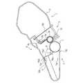
- a cassette 3 is attached in a lower portion of the main body A.
- the cassette 3 contains a recording medium 2 or recording media 2.
- the recording medium 2 or each of the recording media 2 is a sheet of, for example, paper.
- a recording medium conveying device is provided so that the recording media 2 is conveyed to an upper portion of the main body A through a transfer roller 4 and a fixing device 5. More specifically, a feed roller 3c, a conveying roller pair 3d, and a registration roller pair 3e are provided.
- the feed roller 3c separates one sheet after another from the recording media 2 in the cassette 3 and feeds each sheet.
- the conveying roller pair 3d conveys each of the recording media 2 having been fed thereto.
- the registration roller pair 3e synchronizes the latent image formed on the photosensitive drum 7 with the recording medium 2.
- the fixing device 5 that fixes the image formed on the recording medium 2 is provided.
- the cleaning blade 10a is in contact with the surface of the photosensitive drum 7 while the cleaning blade 10a is inclined in a rotational direction of the photosensitive drum 7 relative to a normal to the photosensitive drum 7.
- This cleaning blade 10a causes residual toner removed from the surface of the photosensitive drum 7 to drop into the waste toner chamber 13a.
- the anti-leakage sheet 13b is in contact with the photosensitive drum 7.
- the photosensitive drum 7 is rotated in accordance with image forming operation by transmitting a drive force from the main body A to the cleaning unit C.
- the charging roller 8 is rotatably attached to the cleaning unit C and pressed against the photosensitive drum 7, thereby being rotated by the photosensitive drum 7.
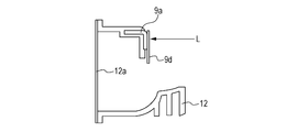
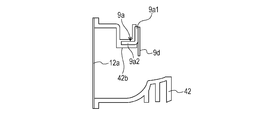
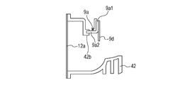
- a laser light L is radiated so as to secured the developing blade 9d to the first support member 9a.
- a developing container lid 12a is joined to the developing container 12 by, for example, ultrasonic welding.
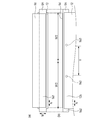
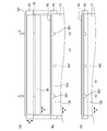
- the shaft of the developing roller 9c is supported by the bearing members (not illustrated) provided at both the ends of the developing container 12 in the longitudinal direction N such that the tip end of the developing blade 9d is disposed on the developing roller 9c, which is the rotating member.
- the developing unit D is thus formed.
- bearing portions may be provided in the developing container 12, so that both the ends of the shaft of the developing roller 9c in the longitudinal direction N are supported by the bearing portions of the developing container 12.
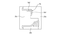
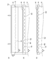
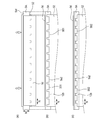
- the movement of the first support member 9a relative to the developing container 12 is regulated in the lateral direction and permitted in the longitudinal direction N by the exposed portions 9A in the developing unit D produced by the method according to the present embodiment. Accordingly, bending or deformation of the first support member 9a, the developing blade 9d secured to the first support member 9a, and the developing container 12 caused by changes in room temperature can be suppressed.
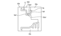
- the developing blade 9d may be secured to the first plate portion 9a1 of the first support member 9a such that the developing blade 9d projects from the side opposite to the side where the first plate portion 9a1 and the second plate portion 9a2 of the first support member 9a are connected to each other toward the side where the first plate portion 9a1 and the second plate portion 9a2 are connected to each other.
- the exposed portion 9A may be formed by exposing an end surface in the longitudinal direction N.
- the end portion or the end portions of the first support member 9a do not necessarily project in the longitudinal direction N as described in the first or second embodiment. With this structure, the effects similar to those of the first embodiment can be obtained.
- the invention according to the present embodiment can be produced in a method similar to that of the first embodiment, and the effects similar to those in the first embodiment can be obtained.
- the cleaning blade 10a and the photosensitive drum 7 are in contact with each other, the occurrence of the difference in contact pressure at which the cleaning blade 10a and the photosensitive drum 7 are in contact with each other in the longitudinal direction N of the photosensitive drum 7 can be suppressed.
- the likelihood of being affected by heat can be easily reduced with a small number of components instead of increasing the number of components.
- the notch portion is provided in the part of the second support member 10c embedded in the cleaning container 13.
- the resin that forms the cleaning container 13 has flowed from the main body side or the securing portion side of the cleaning container 13 into the notch portion of the second support member 10c.
- the second support member 10c can be positioned relative to the cleaning container 13 in the longitudinal direction N.
- the developing blade 9d is directly secured to the first support member 9a according to the above-described embodiments, this is not limiting.
- the first support member 9a may be disposed as a reinforcing member in the resin that forms the developing container 52, and the developing blade 9d may be secured to the developing container 52.
Landscapes
- Physics & Mathematics (AREA)
- General Physics & Mathematics (AREA)
- Engineering & Computer Science (AREA)
- Computer Vision & Pattern Recognition (AREA)
- Life Sciences & Earth Sciences (AREA)
- Manufacturing & Machinery (AREA)
- Sustainable Development (AREA)
- Dry Development In Electrophotography (AREA)
- Electrophotography Configuration And Component (AREA)
- Cleaning In Electrography (AREA)
Priority Applications (2)
| Application Number | Priority Date | Filing Date | Title |
|---|---|---|---|
| US15/319,057 US10048646B2 (en) | 2014-06-17 | 2015-06-12 | Image forming apparatus with frame body and detachable cartridge with integrated photosensitive drum |
| CN201580032327.XA CN106462099B (zh) | 2014-06-17 | 2015-06-12 | 成像设备、盒以及用于所述盒的框架本体 |
Applications Claiming Priority (4)
| Application Number | Priority Date | Filing Date | Title |
|---|---|---|---|
| JP2014124748 | 2014-06-17 | ||
| JP2014-124748 | 2014-06-17 | ||
| JP2015095772A JP6576093B2 (ja) | 2014-06-17 | 2015-05-08 | 画像形成装置、カートリッジ及びそれに用いられる枠体 |
| JP2015-095772 | 2015-05-08 |
Publications (1)
| Publication Number | Publication Date |
|---|---|
| WO2015194144A1 true WO2015194144A1 (en) | 2015-12-23 |
Family
ID=53546677
Family Applications (1)
| Application Number | Title | Priority Date | Filing Date |
|---|---|---|---|
| PCT/JP2015/002952 WO2015194144A1 (en) | 2014-06-17 | 2015-06-12 | Image forming apparatus, cartridge, and frame body used for the cartridge |
Country Status (4)
| Country | Link |
|---|---|
| US (1) | US10048646B2 (ja) |
| JP (1) | JP6576093B2 (ja) |
| CN (1) | CN106462099B (ja) |
| WO (1) | WO2015194144A1 (ja) |
Families Citing this family (3)
| Publication number | Priority date | Publication date | Assignee | Title |
|---|---|---|---|---|
| JP6918473B2 (ja) * | 2016-11-30 | 2021-08-11 | キヤノン株式会社 | 現像装置 |
| US10761452B2 (en) * | 2017-09-07 | 2020-09-01 | Canon Kabushiki Kaisha | Developing device including a resin regulating blade |
| JP7135674B2 (ja) * | 2018-09-28 | 2022-09-13 | ブラザー工業株式会社 | 現像カートリッジ |
Citations (5)
| Publication number | Priority date | Publication date | Assignee | Title |
|---|---|---|---|---|
| JPH11282251A (ja) | 1998-03-30 | 1999-10-15 | Canon Inc | 現像装置及びプロセスカートリッジ |
| WO2006098343A1 (en) * | 2005-03-14 | 2006-09-21 | Ricoh Company, Limited | Unit, image forming apparatus, and method of manufacturing unit frame |
| EP2216691A1 (en) * | 2007-11-14 | 2010-08-11 | Bridgestone Corporation | Die for developing blade and production method of developing blade |
| WO2013094167A1 (en) * | 2011-12-21 | 2013-06-27 | Canon Kabushiki Kaisha | Developing device and process cartridge |
| US20140133893A1 (en) * | 2012-11-13 | 2014-05-15 | Oki Data Corporation | Cleaning device, image forming unit and image forming apparatus |
Family Cites Families (19)
| Publication number | Priority date | Publication date | Assignee | Title |
|---|---|---|---|---|
| JPH01140174A (ja) * | 1987-11-27 | 1989-06-01 | Mitsubishi Petrochem Co Ltd | 電子写真装置用ブレード |
| JPH09190146A (ja) * | 1996-01-09 | 1997-07-22 | Canon Inc | プロセスカートリッジ |
| JP2000132039A (ja) * | 1998-10-26 | 2000-05-12 | Canon Inc | クリーニング枠体及びプロセスカートリッジ及び電子写真画像形成装置 |
| JP2001005285A (ja) * | 1999-06-24 | 2001-01-12 | Canon Inc | 現像装置及びクリーニング装置及びプロセスカートリッジ及び画像形成装置 |
| JP2001198945A (ja) * | 2000-01-18 | 2001-07-24 | Canon Inc | インサート成形方法及び成形用金型及び電子写真用現像ブレード |
| JP3188440B1 (ja) * | 2000-03-07 | 2001-07-16 | キヤノン株式会社 | プロセスカートリッジの再生産方法 |
| JP4180349B2 (ja) * | 2002-10-29 | 2008-11-12 | 株式会社ブリヂストン | 現像ブレードの取出し方法及び現像ブレード成形用金型 |
| JP3966257B2 (ja) * | 2003-08-25 | 2007-08-29 | 村田機械株式会社 | 画像形成装置 |
| JP4335046B2 (ja) * | 2004-03-23 | 2009-09-30 | 株式会社ブリヂストン | 現像剤量規制ブレードの製造方法および現像剤量規制ブレード成型用金型 |
| KR100579514B1 (ko) * | 2005-01-21 | 2006-05-15 | 삼성전자주식회사 | 카트리지의 샤프트를 고정하기 위한 장치 및 그것을 구비한 화상형성장치 |
| JP4746370B2 (ja) * | 2005-07-13 | 2011-08-10 | 藤倉ゴム工業株式会社 | 現像ブレードの製造方法 |
| JP4746369B2 (ja) * | 2005-07-13 | 2011-08-10 | 藤倉ゴム工業株式会社 | 現像ブレードの製造方法 |
| JP5044245B2 (ja) * | 2006-12-15 | 2012-10-10 | 藤倉ゴム工業株式会社 | 現像ブレードおよびその製造方法 |
| JP2008233368A (ja) * | 2007-03-19 | 2008-10-02 | Ricoh Co Ltd | マグネットローラ、現像剤担持体、現像装置、プロセスカートリッジ及び画像形成装置 |
| JP5312626B2 (ja) * | 2008-03-31 | 2013-10-09 | キヤノン株式会社 | 枠体ユニット、現像装置及びプロセスカートリッジ |
| JP5097683B2 (ja) * | 2008-11-14 | 2012-12-12 | 株式会社ブリヂストン | Oa用ブレード |
| JP2012022111A (ja) * | 2010-07-14 | 2012-02-02 | Canon Inc | 現像装置、クリーニング装置、プロセスカートリッジ、画像形成装置 |
| JP5350455B2 (ja) * | 2010-12-16 | 2013-11-27 | キヤノン株式会社 | 電子写真画像形成装置 |
| JP6128780B2 (ja) * | 2012-09-05 | 2017-05-17 | キヤノン株式会社 | 現像装置及びカートリッジ |
-
2015
- 2015-05-08 JP JP2015095772A patent/JP6576093B2/ja active Active
- 2015-06-12 US US15/319,057 patent/US10048646B2/en active Active
- 2015-06-12 WO PCT/JP2015/002952 patent/WO2015194144A1/en active Application Filing
- 2015-06-12 CN CN201580032327.XA patent/CN106462099B/zh active Active
Patent Citations (5)
| Publication number | Priority date | Publication date | Assignee | Title |
|---|---|---|---|---|
| JPH11282251A (ja) | 1998-03-30 | 1999-10-15 | Canon Inc | 現像装置及びプロセスカートリッジ |
| WO2006098343A1 (en) * | 2005-03-14 | 2006-09-21 | Ricoh Company, Limited | Unit, image forming apparatus, and method of manufacturing unit frame |
| EP2216691A1 (en) * | 2007-11-14 | 2010-08-11 | Bridgestone Corporation | Die for developing blade and production method of developing blade |
| WO2013094167A1 (en) * | 2011-12-21 | 2013-06-27 | Canon Kabushiki Kaisha | Developing device and process cartridge |
| US20140133893A1 (en) * | 2012-11-13 | 2014-05-15 | Oki Data Corporation | Cleaning device, image forming unit and image forming apparatus |
Also Published As
| Publication number | Publication date |
|---|---|
| JP2016021050A (ja) | 2016-02-04 |
| JP6576093B2 (ja) | 2019-09-18 |
| CN106462099A (zh) | 2017-02-22 |
| CN106462099B (zh) | 2019-12-10 |
| US20180046136A1 (en) | 2018-02-15 |
| US10048646B2 (en) | 2018-08-14 |
Similar Documents
| Publication | Publication Date | Title |
|---|---|---|
| US10401762B2 (en) | Cartridge and unit | |
| US8879954B2 (en) | Cartridge with member for fixing a member-to-be-energized | |
| US8831487B2 (en) | Regulating device, image bearing member cleaning device, developing device, cleaning device, process cartridge and image forming apparatus | |
| US9581933B2 (en) | Regulating member, developing device and process cartridge | |
| US9367006B2 (en) | Image heating apparatus including a covering member configured to cover an electrode portion | |
| US20060067725A1 (en) | Cartridge, process cartridge, and electrophotographic image forming apparatus | |
| US10048646B2 (en) | Image forming apparatus with frame body and detachable cartridge with integrated photosensitive drum | |
| JP6376841B2 (ja) | カートリッジ及び画像形成装置 | |
| JP2016021050A5 (ja) | ||
| US7280784B2 (en) | Image forming apparatus with conveyance guide member | |
| US9804555B2 (en) | Positioning member and image forming apparatus | |
| KR102128342B1 (ko) | 현상 장치의 재생산 방법 | |
| US20050013635A1 (en) | Developer supply container | |
| JP2006208596A (ja) | 現像剤量規制ブレード | |
| JP7484218B2 (ja) | 現像装置および画像形成装置 | |
| JP6370335B2 (ja) | カートリッジ及びユニットの製造方法 | |
| JP7073205B2 (ja) | 現像装置の製造方法 | |
| KR101978390B1 (ko) | 감광체용 클리닝 블레이드 및 그 제조방법 | |
| JP6590570B2 (ja) | 現像装置の組み立ての方法 | |
| JP2018200462A (ja) | 規制ブレードの固定方法、及び現像装置 | |
| JP2020134885A (ja) | 剥離シート、定着装置及び剥離シートの製造方法 | |
| US20080069591A1 (en) | Gap controlling structure for image forming apparatus | |
| JP2014170042A (ja) | クリーニング装置及びそれを備えたプロセスカートリッジ、及びそのプロセスカートリッジを備えた画像形成装置 | |
| JP5709729B2 (ja) | カートリッジ、及び画像形成装置 | |
| JP2002372859A (ja) | 現像剤量規制ブレード、その製造方法、および、この現像剤量規制ブレードを用いた現像装置 |
Legal Events
| Date | Code | Title | Description |
|---|---|---|---|
| 121 | Ep: the epo has been informed by wipo that ep was designated in this application |
Ref document number: 15738145 Country of ref document: EP Kind code of ref document: A1 |
|
| WWE | Wipo information: entry into national phase |
Ref document number: 15319057 Country of ref document: US |
|
| NENP | Non-entry into the national phase |
Ref country code: DE |
|
| 122 | Ep: pct application non-entry in european phase |
Ref document number: 15738145 Country of ref document: EP Kind code of ref document: A1 |