WO2015194092A1 - 自動ハンドリング装置 - Google Patents
自動ハンドリング装置 Download PDFInfo
- Publication number
- WO2015194092A1 WO2015194092A1 PCT/JP2015/002425 JP2015002425W WO2015194092A1 WO 2015194092 A1 WO2015194092 A1 WO 2015194092A1 JP 2015002425 W JP2015002425 W JP 2015002425W WO 2015194092 A1 WO2015194092 A1 WO 2015194092A1
- Authority
- WO
- WIPO (PCT)
- Prior art keywords
- workpiece
- carrier
- suction head
- holding hole
- work
- Prior art date
- Legal status (The legal status is an assumption and is not a legal conclusion. Google has not performed a legal analysis and makes no representation as to the accuracy of the status listed.)
- Ceased
Links
Images


Classifications
-
- B—PERFORMING OPERATIONS; TRANSPORTING
- B24—GRINDING; POLISHING
- B24B—MACHINES, DEVICES, OR PROCESSES FOR GRINDING OR POLISHING; DRESSING OR CONDITIONING OF ABRADING SURFACES; FEEDING OF GRINDING, POLISHING, OR LAPPING AGENTS
- B24B37/00—Lapping machines or devices; Accessories
- B24B37/27—Work carriers
-
- B—PERFORMING OPERATIONS; TRANSPORTING
- B24—GRINDING; POLISHING
- B24B—MACHINES, DEVICES, OR PROCESSES FOR GRINDING OR POLISHING; DRESSING OR CONDITIONING OF ABRADING SURFACES; FEEDING OF GRINDING, POLISHING, OR LAPPING AGENTS
- B24B37/00—Lapping machines or devices; Accessories
- B24B37/04—Lapping machines or devices; Accessories designed for working plane surfaces
-
- B—PERFORMING OPERATIONS; TRANSPORTING
- B24—GRINDING; POLISHING
- B24B—MACHINES, DEVICES, OR PROCESSES FOR GRINDING OR POLISHING; DRESSING OR CONDITIONING OF ABRADING SURFACES; FEEDING OF GRINDING, POLISHING, OR LAPPING AGENTS
- B24B37/00—Lapping machines or devices; Accessories
- B24B37/27—Work carriers
- B24B37/28—Work carriers for double side lapping of plane surfaces
-
- B—PERFORMING OPERATIONS; TRANSPORTING
- B24—GRINDING; POLISHING
- B24B—MACHINES, DEVICES, OR PROCESSES FOR GRINDING OR POLISHING; DRESSING OR CONDITIONING OF ABRADING SURFACES; FEEDING OF GRINDING, POLISHING, OR LAPPING AGENTS
- B24B37/00—Lapping machines or devices; Accessories
- B24B37/34—Accessories
- B24B37/345—Feeding, loading or unloading work specially adapted to lapping
-
- B—PERFORMING OPERATIONS; TRANSPORTING
- B24—GRINDING; POLISHING
- B24B—MACHINES, DEVICES, OR PROCESSES FOR GRINDING OR POLISHING; DRESSING OR CONDITIONING OF ABRADING SURFACES; FEEDING OF GRINDING, POLISHING, OR LAPPING AGENTS
- B24B41/00—Component parts such as frames, beds, carriages, headstocks
- B24B41/005—Feeding or manipulating devices specially adapted to grinding machines
-
- B—PERFORMING OPERATIONS; TRANSPORTING
- B24—GRINDING; POLISHING
- B24B—MACHINES, DEVICES, OR PROCESSES FOR GRINDING OR POLISHING; DRESSING OR CONDITIONING OF ABRADING SURFACES; FEEDING OF GRINDING, POLISHING, OR LAPPING AGENTS
- B24B41/00—Component parts such as frames, beds, carriages, headstocks
- B24B41/06—Work supports, e.g. adjustable steadies
-
- B—PERFORMING OPERATIONS; TRANSPORTING
- B24—GRINDING; POLISHING
- B24B—MACHINES, DEVICES, OR PROCESSES FOR GRINDING OR POLISHING; DRESSING OR CONDITIONING OF ABRADING SURFACES; FEEDING OF GRINDING, POLISHING, OR LAPPING AGENTS
- B24B57/00—Devices for feeding, applying, grading or recovering grinding, polishing or lapping agents
- B24B57/02—Devices for feeding, applying, grading or recovering grinding, polishing or lapping agents for feeding of fluid, sprayed, pulverised, or liquefied grinding, polishing or lapping agents
-
- B—PERFORMING OPERATIONS; TRANSPORTING
- B25—HAND TOOLS; PORTABLE POWER-DRIVEN TOOLS; MANIPULATORS
- B25J—MANIPULATORS; CHAMBERS PROVIDED WITH MANIPULATION DEVICES
- B25J15/00—Gripping heads and other end effectors
- B25J15/06—Gripping heads and other end effectors with vacuum or magnetic holding means
- B25J15/0616—Gripping heads and other end effectors with vacuum or magnetic holding means with vacuum
-
- B—PERFORMING OPERATIONS; TRANSPORTING
- B25—HAND TOOLS; PORTABLE POWER-DRIVEN TOOLS; MANIPULATORS
- B25J—MANIPULATORS; CHAMBERS PROVIDED WITH MANIPULATION DEVICES
- B25J9/00—Programme-controlled manipulators
- B25J9/02—Programme-controlled manipulators characterised by movement of the arms, e.g. cartesian coordinate type
- B25J9/04—Programme-controlled manipulators characterised by movement of the arms, e.g. cartesian coordinate type by rotating at least one arm, excluding the head movement itself, e.g. cylindrical coordinate type or polar coordinate type
- B25J9/041—Cylindrical coordinate type
- B25J9/042—Cylindrical coordinate type comprising an articulated arm
-
- B—PERFORMING OPERATIONS; TRANSPORTING
- B25—HAND TOOLS; PORTABLE POWER-DRIVEN TOOLS; MANIPULATORS
- B25J—MANIPULATORS; CHAMBERS PROVIDED WITH MANIPULATION DEVICES
- B25J9/00—Programme-controlled manipulators
- B25J9/10—Programme-controlled manipulators characterised by positioning means for manipulator elements
- B25J9/102—Gears specially adapted therefor, e.g. reduction gears
-
- H—ELECTRICITY
- H01—ELECTRIC ELEMENTS
- H01L—SEMICONDUCTOR DEVICES NOT COVERED BY CLASS H10
- H01L21/00—Processes or apparatus adapted for the manufacture or treatment of semiconductor or solid state devices or of parts thereof
- H01L21/02—Manufacture or treatment of semiconductor devices or of parts thereof
- H01L21/04—Manufacture or treatment of semiconductor devices or of parts thereof the devices having potential barriers, e.g. a PN junction, depletion layer or carrier concentration layer
- H01L21/18—Manufacture or treatment of semiconductor devices or of parts thereof the devices having potential barriers, e.g. a PN junction, depletion layer or carrier concentration layer the devices having semiconductor bodies comprising elements of Group IV of the Periodic Table or AIIIBV compounds with or without impurities, e.g. doping materials
- H01L21/30—Treatment of semiconductor bodies using processes or apparatus not provided for in groups H01L21/20 - H01L21/26
- H01L21/302—Treatment of semiconductor bodies using processes or apparatus not provided for in groups H01L21/20 - H01L21/26 to change their surface-physical characteristics or shape, e.g. etching, polishing, cutting
- H01L21/304—Mechanical treatment, e.g. grinding, polishing, cutting
-
- H—ELECTRICITY
- H01—ELECTRIC ELEMENTS
- H01L—SEMICONDUCTOR DEVICES NOT COVERED BY CLASS H10
- H01L21/00—Processes or apparatus adapted for the manufacture or treatment of semiconductor or solid state devices or of parts thereof
- H01L21/02—Manufacture or treatment of semiconductor devices or of parts thereof
- H01L21/04—Manufacture or treatment of semiconductor devices or of parts thereof the devices having potential barriers, e.g. a PN junction, depletion layer or carrier concentration layer
- H01L21/18—Manufacture or treatment of semiconductor devices or of parts thereof the devices having potential barriers, e.g. a PN junction, depletion layer or carrier concentration layer the devices having semiconductor bodies comprising elements of Group IV of the Periodic Table or AIIIBV compounds with or without impurities, e.g. doping materials
- H01L21/30—Treatment of semiconductor bodies using processes or apparatus not provided for in groups H01L21/20 - H01L21/26
- H01L21/302—Treatment of semiconductor bodies using processes or apparatus not provided for in groups H01L21/20 - H01L21/26 to change their surface-physical characteristics or shape, e.g. etching, polishing, cutting
- H01L21/306—Chemical or electrical treatment, e.g. electrolytic etching
- H01L21/30625—With simultaneous mechanical treatment, e.g. mechanico-chemical polishing
-
- H—ELECTRICITY
- H01—ELECTRIC ELEMENTS
- H01L—SEMICONDUCTOR DEVICES NOT COVERED BY CLASS H10
- H01L21/00—Processes or apparatus adapted for the manufacture or treatment of semiconductor or solid state devices or of parts thereof
- H01L21/67—Apparatus specially adapted for handling semiconductor or electric solid state devices during manufacture or treatment thereof; Apparatus specially adapted for handling wafers during manufacture or treatment of semiconductor or electric solid state devices or components ; Apparatus not specifically provided for elsewhere
- H01L21/68—Apparatus specially adapted for handling semiconductor or electric solid state devices during manufacture or treatment thereof; Apparatus specially adapted for handling wafers during manufacture or treatment of semiconductor or electric solid state devices or components ; Apparatus not specifically provided for elsewhere for positioning, orientation or alignment
-
- H—ELECTRICITY
- H01—ELECTRIC ELEMENTS
- H01L—SEMICONDUCTOR DEVICES NOT COVERED BY CLASS H10
- H01L21/00—Processes or apparatus adapted for the manufacture or treatment of semiconductor or solid state devices or of parts thereof
- H01L21/67—Apparatus specially adapted for handling semiconductor or electric solid state devices during manufacture or treatment thereof; Apparatus specially adapted for handling wafers during manufacture or treatment of semiconductor or electric solid state devices or components ; Apparatus not specifically provided for elsewhere
- H01L21/683—Apparatus specially adapted for handling semiconductor or electric solid state devices during manufacture or treatment thereof; Apparatus specially adapted for handling wafers during manufacture or treatment of semiconductor or electric solid state devices or components ; Apparatus not specifically provided for elsewhere for supporting or gripping
- H01L21/6838—Apparatus specially adapted for handling semiconductor or electric solid state devices during manufacture or treatment thereof; Apparatus specially adapted for handling wafers during manufacture or treatment of semiconductor or electric solid state devices or components ; Apparatus not specifically provided for elsewhere for supporting or gripping with gripping and holding devices using a vacuum; Bernoulli devices
Definitions
- the present invention relates to an automatic handling apparatus that automatically conveys a workpiece such as a silicon wafer.
- a double-sided processing device such as a double-side polishing device or a double-sided lapping device
- a double-sided processing device such as a double-side polishing device or a double-sided lapping device
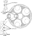
- a double-side polishing apparatus a disk-shaped planetary gear called a carrier is disposed between upper and lower surface plates to which polishing pads made of foamed urethane or nonwoven fabric are attached.
- the work is penetrated and held in the holding hole of the carrier, and the sun gear and the internal gear meshing with the carrier are rotated with each other, thereby causing the carrier to rotate or revolve.
- the upper and lower surfaces of the workpiece are polished simultaneously by the rotation, revolution, and rotation of the upper and lower surface plates and sliding of the workpiece.
- polishing slurry is supplied from a plurality of holes provided in the upper surface plate during double-side polishing.
- the upper platen is equipped with a mechanism that moves up and down, and after the upper platen is in the raised position, a carrier is set on the lower platen, and a work is set on the set carrier.
- the operator sets the workpiece on the carrier manually by the operator, or when using an automatic handling device. In this way, after the work is loaded, the upper surface plate descends, and the work and the carrier are sandwiched between the upper and lower surface plates. Then, while supplying the polishing slurry, the workpiece is polished by the rotation and revolution of the carrier obtained by the rotation of the upper and lower surface plates and the rotation of the internal gear and the sun gear.
- silicon wafers In the processing process of silicon wafers, it is generally promoted to automatically prepare and take out silicon wafer processing process equipment from processing by an operator using a robot or the like, thereby reducing labor costs. This contributes to reducing the manufacturing cost of silicon wafers.
- one carrier or a plurality of workpieces can be held by one carrier, and a plurality of carriers, for example, five carriers are provided in the apparatus at equal intervals, that is, at 72 ° intervals. In many cases.
- the target carrier When holding the work on the carrier, the target carrier is moved to a specific work loading position by rotating the internal gear and the sun gear among the plurality of carriers.
- the workpiece is held with respect to the carrier arranged at this specific preparation position.
- the internal gear and the sun gear are rotated in the same direction by 72 ° to move the next adjacent carrier to the preparation position of the work (this operation is carried out by the carrier). May be referred to as the index).
- the internal gear and the sun gear are controlled to stop the position of the carrier at a desired position, but these gears usually have backlash, and there is uncertainty about the stop position according to this size. Arise. Furthermore, the carrier meshes with the sun gear and the internal gear and is set in the apparatus. As shown in FIG. 10, it is common to provide a clearance between the carrier and both gears. This is a factor that reduces accuracy.
- a wafer having a diameter of 200 mm or a diameter of 300 mm is currently the mainstream, and therefore, depending on the backlash when the wafer hand grabs the wafer or the clearance between the carrier and the gear.
- the reduction in position accuracy on the order of millimeters is often not a problem because it is sufficiently small compared to the workpiece size.
- the diameter of the workpiece holding hole of the carrier is usually designed to be at most about 1 mm or less than the diameter of the workpiece, the above instability of the carrier position accuracy cannot be eliminated. As long as it is repeated, the workpiece cannot be accurately loaded into the workpiece holding hole.
- Patent Document 1 devises an apparatus that optically measures the position of the carrier and the position of the work holding hole and loads the work at a position corresponding to the measurement result.
- the software required for introducing the optical device, calculating the position of the workpiece holding hole from the image information, and controlling the workpiece loading position accordingly requires a large introduction cost.
- the present invention has been made in view of the above-described problems, and an object thereof is to provide an automatic handling apparatus that can accurately and inexpensively charge a workpiece into a workpiece holding hole of a carrier.
- a workpiece double-side machining apparatus having a workpiece holding carrier that meshes with a sun gear and an internal gear to perform planetary gear motion, the workpiece is placed in the workpiece holding hole of the carrier.
- An automatic handling apparatus for carrying in or carrying out a work from a work holding hole of the carrier, the suction head for sucking and holding the work, an arm connected to the suction head and moving the suction head, and the work holding of the carrier A stage on which a work to be transported in the hole is placed; and the suction head has a movable part movable in a horizontal plane with respect to the main body of the suction head, and the movable part It has a plurality of positioning pins that can be sucked and held and extended vertically downward, and the plurality of positioning pins are movable.
- an automatic handling apparatus characterized in that the position and orientation of the carrier are fixed and the held work is carried into the holding hole of the carrier.
- the carrier is pressed to the sun gear side by the plurality of positioning pins, and the carrier is always fixed in a predetermined position and orientation, and then the workpiece is charged into the workpiece holding hole.
- the workpiece can be prepared at the position.
- this automatic handling device does not have a particularly complicated structure and does not require expensive optical equipment. Therefore, it is possible to accurately load the workpiece into the carrier holding hole without introducing expensive equipment such as an optical device or an image processing apparatus, and it is possible to realize conveyance of the workpiece with low cost and high accuracy.
- the stage has a position where the center of the work held by the movable portion and the center of the work holding hole of the carrier coincide with each other. It is preferable that a mechanism capable of placing the workpiece is provided.
- the workpiece can be conveyed with higher accuracy.
- the stage has a plurality of positioning holes into which the plurality of positioning pins are inserted when the movable portion sucks and holds the workpiece placed on the stage.
- the position of the positioning hole is such that the relative position between the movable part and the workpiece placed on the stage is determined by the plurality of positioning pins indicating the position and orientation of the carrier.
- the movable portion is adjusted so that the movable portion can hold the workpiece at a position where the center of the workpiece held by the movable portion coincides with the center of the workpiece holding hole. it can.
- the suction head since the suction head has a positioning pin in the movable portion, the positioning head is held by the movable portion with a simpler structure by inserting such a positioning pin into the positioning hole.
- the workpiece can be held at a position where the center of the workpiece and the center of the workpiece holding hole coincide with each other, and the workpiece can be conveyed more simply and accurately.
- the automatic handling apparatus of the present invention does not necessarily require expensive optical equipment and image processing apparatus, and can accurately and accurately load a work into the work holding hole of the carrier.
- the present invention is not limited to this.
- a double-sided processing device such as a double-side polishing device or a double-sided lapping device
- the position of the carrier and the clearance between the sun gear and the internal gear and the carrier are Since the direction is not constant, there is a problem that the workpiece cannot be accurately loaded.
- a device has been devised that optically measures the position of the carrier and the position of the work holding hole, and loads the work at a position corresponding to the measurement result, but it requires a large introduction cost to the optical device or the like. There is a problem.
- an automatic handling device that can fix the position and orientation of the carrier with a positioning pin when loading a workpiece can convey the workpiece with high accuracy at a low cost with a simple structure. was completed.
- an automatic handling apparatus 1 includes a double-sided processing apparatus 20 (see FIG. 1) having a work holding carrier 23 that meshes with a sun gear 21 and an internal gear 22 on a lower surface plate 25 to make planetary gear movement. 1, a double-side polishing apparatus is exemplified), and the workpiece W is carried into or out of the workpiece holding hole 24 of the carrier 23.
- This automatic handling device 1 is connected to the suction head 2 for sucking and holding the workpiece W, the arm 3 for moving the suction head 2, and the workpiece holding hole 24 of the carrier 23 in the double-side processing apparatus 20.
- a stage 4 on which the workpiece W is placed is provided.
- the stage 4 can also be loaded with the workpiece W that has been taken out of the workpiece holding hole 24 and has been processed.
- the double-sided processing apparatus 20 having five carriers is illustrated, but the number of carriers is not limited to five.
- the work W placed on the stage 4 is first sucked and held by the suction head 2. Then, the suction head 2 is moved above the carrier 23 by the arm 3, the work W is positioned above the work holding hole 24, the suction holding by the suction head 2 is released, and the work W is placed in the work holding hole 24. Prepare.
- the suction head 2 of the automatic handling apparatus 1 of the present invention has a movable portion 5 that can move in a horizontal plane with respect to the main body 8 of the suction head.
- the movable portion 5 has a plurality of positioning pins 6 that can hold the workpiece W by suction and extend vertically downward.
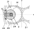
- the suction head 2 is a space in which a plurality of positioning pins 6 are sandwiched between the carrier 23, the internal gear 22, and the lower surface plate 25 before the work W is loaded into the work holding hole 24. Inserted into.
- the plurality of positioning pins 6 can press the carrier 23 against the sun gear 21 side. By pressing the carrier 23 toward the sun gear 21, the gap between the sun gear 21 and the carrier 23 can be substantially eliminated (that is, the carrier position in the x direction (the center direction of the lower surface plate 25) in FIG. 2 is determined).
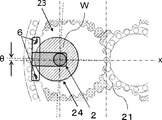
- the movable portion 5 of the suction head 2 is moved in accordance with the direction ⁇ of the carrier 23 so that all the positioning pins 6 are in close contact with the carrier 23, specifically, the positioning pins 6 are in close contact with the tooth bottom of the carrier 23. Can also be tilted by ⁇ .
- the automatic handling apparatus of the present invention having such a suction head 2, the relationship between the position and orientation of the movable portion 5 that sucks the workpiece and the carrier 23 is always the same even if the carrier stop position accuracy is not sufficient. Therefore, the work can be accurately prepared. Further, this automatic handling apparatus does not require measurement of the position of the work holding hole by an expensive optical device or the like. Therefore, it is possible to accurately charge the workpiece into the carrier holding hole without introducing an optical device or the like, and it is possible to realize low-cost and highly accurate workpiece charging.
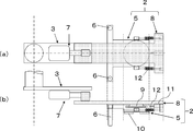
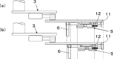
- the suction head 2 is attached to a pivotable arm 3, and an expansion / contraction function by a first air cylinder 7 is added to the arm 3.
- the work W is taken out from the work holding hole 24 in a state where the arm 3 is contracted, and the work W is charged in a state where the arm 3 is extended.
- the suction head 2 has an upper part (main body 8 of the suction head) fixed to the arm 3, and a main body 8 of the suction head via a slide bearing 9.
- the connected lower part (movable part 5) has a two-stage structure, and the movable part 5 is movable with respect to the main body 8 in a horizontal plane.
- the part that actually holds the workpiece W by suction is the movable portion 5, and the suction pad 10 is attached to the lower surface of the movable portion 5, and the workpiece W is vacuum-sucked and held by this suction pad 10.
- the movable portion 5 has a plate fixed to the movable portion 5, and a plurality of positioning pins 6 extending vertically downward are attached to the plate. 5 illustrates the case where the number of positioning pins 6 is two, of course, the number of positioning pins 6 may be three or more.
- the plate to which the movable portion 5 having a movable range in the horizontal plane and the positioning pin 6 are attached to the main body 8 of the suction head is an integral structure, when the movable portion 5 moves relative to the main body 8, the positioning pin 6 is also interlocked therewith. And can move.
- the main body 8 of the suction head is provided with a second air cylinder 11 that moves the movable portion 5 and the positioning pin 6, which are integrally structured, in the movable range of the sliding bearing 9 toward the base of the arm 3. ing.
- the main body 8 of the suction head 2 and the movable portion 5 are extended on the distal end side of the suction head 2 so that the movable portion 5 can be corrected and held in the distal direction of the arm 3 in the range of the movable area of the movable portion 5. It is connected via a spring 12 in a state (a state in which the spring 12 has a force to contract toward the tip of the arm 3).
- the movable portion 5 comes into contact with the tip of the second air cylinder 11 and is pulled toward the tip of the arm 3 by the spring 12, so that the main body 8 of the suction head is attached. It is fixed against.
- the second air cylinder 11 is not extended, that is, when the movable part 5 is not fixed by the second air cylinder 11, the movable part 5 can move within the range of the sliding bearing 9.
- an arm using an articulated robot may be used instead of the pivotable arm 3.
- the telescopic function of the arm 3, that is, the first air cylinder 7 may be omitted.
- the second air cylinder 11 that pushes the movable portion 5 toward the arm base side may be a cylinder of a mechanism using a motor or a magnet. Or you may use the mechanism using the compliance unit which can move the movable part 5 to the base side when the movable part 5 is fixed.
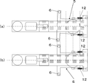
- the carrier 23 is put on standby at the workpiece loading position by controlling the stop positions of the sun gear 21 and the internal gear 22.
- the arm 3 is turned, and the work W sucked by the suction head 2 is made to enter above the carrier 23.
- the second air cylinder 11 is extended and the movable part 5 is fixed, and then the movable part 5 holding the work W is moved slightly from the surface of the carrier 23. Lower to a higher position.
- the plurality of positioning pins 6 are attached at positions where they do not touch any of the lower surface plate 25, the carrier 23, and the internal gear 22 in FIG.
- the second air cylinder 11 is contracted, so that the movable portion 5 and the positioning pin 6 are released from the state of being pushed in the root direction of the arm 3, and the spring 12 is moved relative to the arm tip direction, that is, toward the sun gear 21 in FIG. 1, and the gap between the positioning pin 6 and the carrier 23 is reduced or contact is started.
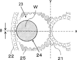
- the positioning pin 6 and the carrier 23 start to contact, the carrier 23 is pushed to the sun gear 21 side by the positioning pin 6, and the clearance between the carrier 23 and the sun gear 21 side becomes small or becomes zero.
- the movable portion 5 and the positioning pin 6 are further tilted toward the sun gear side from the state of FIG. 7B by being pulled by the force of the spring 12.
- the main body 8 of the suction head and the movable portion 5 are connected via the sliding bearing 9, even if the carrier 23 is placed at a position with an inclination in the ⁇ direction, the plurality of positioning pins 6 are provided with the carrier.
- the movable portion 5 moves while tilting so as to be in close contact with the tooth bottom of the outer peripheral gear 23.
- the carrier 23 is pushed toward the sun gear 21 by the force of the spring 12 to further shrink, and the clearance between the carrier 23 and the sun gear 21 becomes zero. That is, the position and orientation of the carrier 23 are fixed by the sun gear 21 and the plurality of positioning pins 6.
- the arm 3 and the suction head 2 are lowered until the work W is further placed in the work holding hole 24 of the carrier 23 to release the suction holding, so that the work W is accurately charged into the work holding hole 24. Can do.
- the suction head 2 that has released the workpiece suction and holding is lifted slightly, and then the second air cylinder 11 is extended to move the movable part 5 toward the base of the arm 3, and the contact between the positioning pin 6 and the carrier 23.
- the double-sided processing apparatus 20 indexes the carrier 23 by 72 ° and prepares for the preparation of the next workpiece. By repeating these operations five times, workpieces can be loaded on all five carriers.
- the stage 4 is configured such that when the suction head 2 sucks the work W carried into the work holding hole 24 of the carrier 23, the plurality of positioning pins 6 fix the position and orientation of the carrier 23.
- a mechanism capable of placing the workpiece W at a position where the center of the workpiece W held by the movable portion 5 coincides with the center of the workpiece holding hole 24 of the carrier 23 is preferably provided.
- the stage 4 may have a plurality of positioning holes into which the plurality of positioning pins 6 are inserted when the movable portion 5 sucks and holds the workpiece W placed on the stage 4.
- the positions of the plurality of positioning holes are such that when the plurality of positioning pins 6 are inserted, the relative position between the movable portion 5 and the workpiece W placed on the stage 4 is determined by the plurality of positioning pins 6 being the carrier.
- the movable part 5 is adjusted so that the movable part 5 can hold the work W at a position where the center of the work W held by the movable part 5 coincides with the center of the work holding hole 24. It is preferable that
- the stage for placing the work carried into the work holding hole 24 is provided with a work centering mechanism, and the position of the work W placed manually or automatically on the stage is always set. Can be the same.
- a pusher 14 composed of, for example, an air cylinder or the like pushes a work placed on a plurality of work support portions 13 in one direction to hold the work on the opposite side of the pusher 14. The position of the same workpiece W is always obtained by fixing the workpiece W with the workpiece support portion 13.
- the stage 4 is provided with a plurality of positioning holes 15 into which a plurality of positioning pins 6 included in the suction head 2 are inserted.
- These positioning holes 15 are inserted into the positioning pins 6 regardless of the expansion / contraction position of the second air cylinder 11 shown in FIGS. 6A and 6B when the suction head 2 is lowered. Thus, it has a diameter larger than the diameter of the positioning pin 6.
- the plurality of positioning pins 6 are connected to the inner walls of the plurality of positioning holes 15. It is installed at the position where it comes into contact.
- the center of the workpiece W is made to coincide with the center of the workpiece holding hole 24 when the positioning pin 6 and the carrier 23 contact in the workpiece loading operation described above.
- the position of the positioning hole 15 is adjusted.
- the suction head 2 that has swung on the stage 4 is lowered with the second air cylinder 11 extended.
- the suction surface of the suction head 2 reaches slightly above the surface of the workpiece W, the descent is stopped and the second air cylinder 11 is contracted.
- the movable portion 5 released from the second air cylinder 11 is pulled toward the distal end of the arm 3 by the force of the spring 12, and the plurality of positioning pins 6 are in complete contact with the inner wall of the positioning hole 15.
- the work W is sucked and held, and after being lifted, the work W is turned to the work preparation position. From here, the workpiece W is loaded into the workpiece holding hole 24 of the carrier 23 by the aforementioned workpiece loading operation.
- the automatic handling apparatus includes a stage having a positioning hole corresponding to the positioning pin of the suction head, the center of the work held by the movable part and the center of the work holding hole with a simple stage structure It is possible to hold the workpiece at a position where they coincide with each other, and the workpiece can be loaded more simply and accurately.
- the carrier 23 holding the workpiece W is put on standby at the workpiece loading position in the same manner as the loading operation.
- the suction hand 2 is introduced above the workpiece W by turning the arm 3.
- the first air cylinder 7 can be kept in a contracted state.
- the suction head 2 is positioned on the internal gear 22 side as compared with the charging operation, but is still positioned above the workpiece W.
- the suction head 2 descends to a position where the suction pad 10 contacts the workpiece W, and holds the workpiece W by suction. Since the positioning pin 6 is outside the internal gear 22, it can be lowered without contacting the internal gear 22 or the carrier 23. Subsequently, the suction head 2 that has sucked the workpiece is raised, turned to the automatic handling device side, the workpiece W is placed on the stage 4, and then the workpiece is released. At this time, as shown in FIG. 9, the arm 3 is operating in a contracted state. Therefore, when the arm 3 is lowered to place the workpiece W on the stage 4, the positioning pins 6 are positioned in the positioning holes of the stage 4. 15 can be lowered to the outside. Next, the arm 3 and the suction head 2 are raised, the carrier 23 is indexed, and moved to the next workpiece W take-out position. By repeating these operations five times, the removal of all the workpieces W is completed.
- Example 1 Using the automatic handling apparatus 1 of the present invention as shown in FIG. 1, after carrying a silicon wafer into the work holding hole of the carrier of the double-side polishing apparatus 20 and performing double-side polishing according to the above-described workpiece loading and unloading operations The silicon wafers were repeatedly carried out from the workpiece holding holes, and a total of 3000 silicon wafers having a diameter of 300 mm were carried in and out. At this time, the stage has a positioning hole, and the movable portion of the suction head can hold the workpiece at a position where the center of the silicon wafer held by the movable portion coincides with the center of the workpiece holding hole. What was adjusted so that it was used.
- the present invention is not limited to the above embodiment.
- the above-described embodiment is an exemplification, and the present invention has any configuration that has substantially the same configuration as the technical idea described in the claims of the present invention and that exhibits the same effects. Are included in the technical scope.
Landscapes
- Engineering & Computer Science (AREA)
- Mechanical Engineering (AREA)
- Computer Hardware Design (AREA)
- Condensed Matter Physics & Semiconductors (AREA)
- General Physics & Mathematics (AREA)
- Manufacturing & Machinery (AREA)
- Physics & Mathematics (AREA)
- Microelectronics & Electronic Packaging (AREA)
- Power Engineering (AREA)
- Robotics (AREA)
- Finish Polishing, Edge Sharpening, And Grinding By Specific Grinding Devices (AREA)
- Manipulator (AREA)
- Container, Conveyance, Adherence, Positioning, Of Wafer (AREA)
- Constituent Portions Of Griding Lathes, Driving, Sensing And Control (AREA)
- Mechanical Treatment Of Semiconductor (AREA)
Priority Applications (5)
| Application Number | Priority Date | Filing Date | Title |
|---|---|---|---|
| SG11201610298XA SG11201610298XA (en) | 2014-06-16 | 2015-05-13 | Automatic handling apparatus |
| DE112015002397.6T DE112015002397T5 (de) | 2014-06-16 | 2015-05-13 | Automatische Handhabungsvorrichtung |
| US15/314,982 US9931730B2 (en) | 2014-06-16 | 2015-05-13 | Automatic handling apparatus with positioning pins |
| CN201580028464.6A CN106660191B (zh) | 2014-06-16 | 2015-05-13 | 自动装卸装置 |
| KR1020167034602A KR102150406B1 (ko) | 2014-06-16 | 2015-05-13 | 자동 핸들링 장치 |
Applications Claiming Priority (2)
| Application Number | Priority Date | Filing Date | Title |
|---|---|---|---|
| JP2014-123518 | 2014-06-16 | ||
| JP2014123518A JP6183301B2 (ja) | 2014-06-16 | 2014-06-16 | 自動ハンドリング装置 |
Publications (1)
| Publication Number | Publication Date |
|---|---|
| WO2015194092A1 true WO2015194092A1 (ja) | 2015-12-23 |
Family
ID=54935108
Family Applications (1)
| Application Number | Title | Priority Date | Filing Date |
|---|---|---|---|
| PCT/JP2015/002425 Ceased WO2015194092A1 (ja) | 2014-06-16 | 2015-05-13 | 自動ハンドリング装置 |
Country Status (8)
| Country | Link |
|---|---|
| US (1) | US9931730B2 (enExample) |
| JP (1) | JP6183301B2 (enExample) |
| KR (1) | KR102150406B1 (enExample) |
| CN (1) | CN106660191B (enExample) |
| DE (1) | DE112015002397T5 (enExample) |
| SG (1) | SG11201610298XA (enExample) |
| TW (1) | TWI594841B (enExample) |
| WO (1) | WO2015194092A1 (enExample) |
Cited By (1)
| Publication number | Priority date | Publication date | Assignee | Title |
|---|---|---|---|---|
| CN116000958A (zh) * | 2022-12-28 | 2023-04-25 | 力鼎智能装备(青岛)集团有限公司 | 一种手腕设备及夹取方法 |
Families Citing this family (11)
| Publication number | Priority date | Publication date | Assignee | Title |
|---|---|---|---|---|
| JP6922467B2 (ja) * | 2016-07-08 | 2021-08-18 | Agc株式会社 | 被処理部材の位置決め装置、処理装置、位置決め方法およびガラス板の製造方法 |
| CN108561532A (zh) * | 2018-04-28 | 2018-09-21 | 湖南宇晶机器股份有限公司 | 分体局部升降式齿圈结构 |
| CN108515450B (zh) * | 2018-06-08 | 2023-08-01 | 新乡日升数控轴承装备股份有限公司 | 用于研磨机上料的工装及研磨机的上料方法 |
| JP7162551B2 (ja) * | 2019-02-18 | 2022-10-28 | 株式会社ディスコ | 加工装置 |
| CN111136573B (zh) * | 2019-11-27 | 2021-12-03 | 常州市瑞得通讯科技有限公司 | 一种高稳定、低损耗陶瓷滤波器制备流水线 |
| KR102262418B1 (ko) * | 2020-03-05 | 2021-06-08 | 주식회사 클레버 | 이차전지 셀의 폴딩 공정용 이차전지 셀 이송 장치 |
| CN112103211B (zh) * | 2020-08-21 | 2024-03-12 | 大连佳峰自动化股份有限公司 | 多头芯片拾取绑定机构 |
| CN113427383A (zh) * | 2021-07-27 | 2021-09-24 | 成都市瑞研光科技有限公司 | 一种智能抛光机 |
| CN114834898A (zh) * | 2022-03-28 | 2022-08-02 | 中环领先半导体材料有限公司 | 磨片下料自动取片装置 |
| CN114800109A (zh) * | 2022-06-27 | 2022-07-29 | 苏州博宏源机械制造有限公司 | 双面抛光机及其抛光方法 |
| CN118875967B (zh) * | 2024-09-23 | 2024-12-13 | 北京特思迪半导体设备有限公司 | 一种游星轮外圈滚道装置以及外圈驱动系统 |
Citations (5)
| Publication number | Priority date | Publication date | Assignee | Title |
|---|---|---|---|---|
| JPS58217268A (ja) * | 1982-06-11 | 1983-12-17 | Supiide Fuamu Kk | 平面研削装置 |
| JPS61241060A (ja) * | 1985-04-17 | 1986-10-27 | Supiide Fuamu Kk | 平面自動研磨装置 |
| JP2000042913A (ja) * | 1998-07-22 | 2000-02-15 | Fujikoshi Mach Corp | 両面研磨装置のワーク給排システム |
| JP2005243996A (ja) * | 2004-02-27 | 2005-09-08 | Shin Etsu Handotai Co Ltd | 半導体ウエーハ用キャリアの保持孔検出装置及び検出方法並びに半導体ウエーハの研磨方法 |
| JP2008110477A (ja) * | 2008-02-01 | 2008-05-15 | Sumitomo Metal Fine Technology Co Ltd | 両面研摩装置 |
Family Cites Families (7)
| Publication number | Priority date | Publication date | Assignee | Title |
|---|---|---|---|---|
| JPS6368359A (ja) | 1986-09-10 | 1988-03-28 | Otani Reiji | ラツピングマシンのキヤリヤ単位ワ−ク同時装填及キヤリヤスライド心出し位置決め方法 |
| US5174067A (en) * | 1990-10-19 | 1992-12-29 | Shin-Etsu Handotai Co., Ltd. | Automatic wafer lapping apparatus |
| JPH11179649A (ja) * | 1997-12-16 | 1999-07-06 | Speedfam Co Ltd | ワークの取出方法及びワーク取出機構付き平面研磨装置 |
| JP2008114342A (ja) * | 2006-11-06 | 2008-05-22 | Nakamura Tome Precision Ind Co Ltd | 基板加工機のワークローダ |
| JP4357551B2 (ja) * | 2007-08-21 | 2009-11-04 | 株式会社春近精密 | ワーク搬送装置のワーク搬送方法 |
| JP5493633B2 (ja) * | 2009-09-18 | 2014-05-14 | 株式会社Sumco | 研磨方法及びその装置 |
| JP5872947B2 (ja) * | 2012-04-05 | 2016-03-01 | 光洋機械工業株式会社 | 両頭平面研削におけるワーク搬入出方法及び両頭平面研削盤 |
-
2014
- 2014-06-16 JP JP2014123518A patent/JP6183301B2/ja active Active
-
2015
- 2015-05-13 SG SG11201610298XA patent/SG11201610298XA/en unknown
- 2015-05-13 WO PCT/JP2015/002425 patent/WO2015194092A1/ja not_active Ceased
- 2015-05-13 US US15/314,982 patent/US9931730B2/en active Active
- 2015-05-13 KR KR1020167034602A patent/KR102150406B1/ko active Active
- 2015-05-13 CN CN201580028464.6A patent/CN106660191B/zh active Active
- 2015-05-13 DE DE112015002397.6T patent/DE112015002397T5/de active Granted
- 2015-05-26 TW TW104116735A patent/TWI594841B/zh active
Patent Citations (5)
| Publication number | Priority date | Publication date | Assignee | Title |
|---|---|---|---|---|
| JPS58217268A (ja) * | 1982-06-11 | 1983-12-17 | Supiide Fuamu Kk | 平面研削装置 |
| JPS61241060A (ja) * | 1985-04-17 | 1986-10-27 | Supiide Fuamu Kk | 平面自動研磨装置 |
| JP2000042913A (ja) * | 1998-07-22 | 2000-02-15 | Fujikoshi Mach Corp | 両面研磨装置のワーク給排システム |
| JP2005243996A (ja) * | 2004-02-27 | 2005-09-08 | Shin Etsu Handotai Co Ltd | 半導体ウエーハ用キャリアの保持孔検出装置及び検出方法並びに半導体ウエーハの研磨方法 |
| JP2008110477A (ja) * | 2008-02-01 | 2008-05-15 | Sumitomo Metal Fine Technology Co Ltd | 両面研摩装置 |
Cited By (1)
| Publication number | Priority date | Publication date | Assignee | Title |
|---|---|---|---|---|
| CN116000958A (zh) * | 2022-12-28 | 2023-04-25 | 力鼎智能装备(青岛)集团有限公司 | 一种手腕设备及夹取方法 |
Also Published As
| Publication number | Publication date |
|---|---|
| DE112015002397T5 (de) | 2017-02-23 |
| US9931730B2 (en) | 2018-04-03 |
| TW201600232A (zh) | 2016-01-01 |
| CN106660191A (zh) | 2017-05-10 |
| TWI594841B (zh) | 2017-08-11 |
| KR20170018833A (ko) | 2017-02-20 |
| KR102150406B1 (ko) | 2020-09-01 |
| CN106660191B (zh) | 2018-06-29 |
| JP2016002612A (ja) | 2016-01-12 |
| JP6183301B2 (ja) | 2017-08-23 |
| US20170190019A1 (en) | 2017-07-06 |
| SG11201610298XA (en) | 2017-01-27 |
Similar Documents
| Publication | Publication Date | Title |
|---|---|---|
| JP6183301B2 (ja) | 自動ハンドリング装置 | |
| CN101959643B (zh) | 工件移送装置 | |
| TWI601193B (zh) | 多功能晶圓及膜片架操作系統 | |
| TWI636858B (zh) | Substrate transfer robot and substrate processing system | |
| TWI487059B (zh) | 用於置中晶圓的裝置 | |
| WO2007097147A1 (ja) | 搬送装置及び搬送方法 | |
| CN114603527A (zh) | 适用于晶圆检测的晶圆夹持机构及翻旋转系统 | |
| JP2014000654A (ja) | ロボットハンド | |
| JP2013172122A (ja) | ダイボンダ | |
| JP6202962B2 (ja) | 切削装置 | |
| JP2016201421A (ja) | 被加工物の搬送トレー | |
| JP2016039185A (ja) | 基板ホルダおよび基板着脱方法 | |
| JP5866658B2 (ja) | 位置決め機構 | |
| JP2006019544A (ja) | 基板移載装置および基板搬送システム | |
| JP2002184725A (ja) | ラップ盤及びその制御法並びにラップ盤用ワーク搬出入装置 | |
| JP4621261B2 (ja) | 両面研摩装置 | |
| CN114473847B (zh) | 一种旋转式晶圆交互系统 | |
| JP7236527B2 (ja) | ワークの保持装置、及び、ワークの保持方法 | |
| WO2015040915A1 (ja) | 搬入出装置および搬入出方法 | |
| JP2008183695A (ja) | 部品組立装置 | |
| JP4947675B1 (ja) | 研磨システム | |
| JP2008006578A (ja) | 磁気ディスク用基板の取り出し方法および磁気ディスク用基板の表面加工装置 | |
| JP6408947B2 (ja) | 工作機械 | |
| JP6573168B2 (ja) | 板ガラスの製造方法及び製造装置 | |
| JP2000326222A (ja) | 両面研摩方法及び装置 |
Legal Events
| Date | Code | Title | Description |
|---|---|---|---|
| 121 | Ep: the epo has been informed by wipo that ep was designated in this application |
Ref document number: 15810114 Country of ref document: EP Kind code of ref document: A1 |
|
| WWE | Wipo information: entry into national phase |
Ref document number: 15314982 Country of ref document: US |
|
| ENP | Entry into the national phase |
Ref document number: 20167034602 Country of ref document: KR Kind code of ref document: A |
|
| WWE | Wipo information: entry into national phase |
Ref document number: 112015002397 Country of ref document: DE |
|
| 122 | Ep: pct application non-entry in european phase |
Ref document number: 15810114 Country of ref document: EP Kind code of ref document: A1 |