WO2015190240A1 - Élément d'encadrement et dispositif d'affichage pour véhicule - Google Patents
Élément d'encadrement et dispositif d'affichage pour véhicule Download PDFInfo
- Publication number
- WO2015190240A1 WO2015190240A1 PCT/JP2015/064300 JP2015064300W WO2015190240A1 WO 2015190240 A1 WO2015190240 A1 WO 2015190240A1 JP 2015064300 W JP2015064300 W JP 2015064300W WO 2015190240 A1 WO2015190240 A1 WO 2015190240A1
- Authority
- WO
- WIPO (PCT)
- Prior art keywords
- light
- bezel
- vehicle
- guide member
- light guide
- Prior art date
Links
- 230000002093 peripheral effect Effects 0.000 claims description 58
- 230000004308 accommodation Effects 0.000 claims description 37
- 238000009792 diffusion process Methods 0.000 claims description 9
- 229920003002 synthetic resin Polymers 0.000 description 29
- 239000000057 synthetic resin Substances 0.000 description 29
- 239000011521 glass Substances 0.000 description 23
- 239000000919 ceramic Substances 0.000 description 21
- 230000007423 decrease Effects 0.000 description 17
- 239000000758 substrate Substances 0.000 description 15
- 239000000428 dust Substances 0.000 description 14
- NIXOWILDQLNWCW-UHFFFAOYSA-N acrylic acid group Chemical group C(C=C)(=O)O NIXOWILDQLNWCW-UHFFFAOYSA-N 0.000 description 13
- 238000001514 detection method Methods 0.000 description 13
- 239000000463 material Substances 0.000 description 13
- 230000004048 modification Effects 0.000 description 13
- 238000012986 modification Methods 0.000 description 13
- 229920000515 polycarbonate Polymers 0.000 description 13
- 239000004417 polycarbonate Substances 0.000 description 13
- 230000007246 mechanism Effects 0.000 description 11
- 239000012780 transparent material Substances 0.000 description 10
- 230000002829 reductive effect Effects 0.000 description 9
- 230000003287 optical effect Effects 0.000 description 8
- 229920005989 resin Polymers 0.000 description 8
- 239000011347 resin Substances 0.000 description 8
- 238000013459 approach Methods 0.000 description 7
- 238000000034 method Methods 0.000 description 6
- 238000012545 processing Methods 0.000 description 6
- 238000013461 design Methods 0.000 description 4
- 230000036961 partial effect Effects 0.000 description 4
- 230000008569 process Effects 0.000 description 4
- 239000004973 liquid crystal related substance Substances 0.000 description 3
- 230000007480 spreading Effects 0.000 description 3
- 230000002238 attenuated effect Effects 0.000 description 2
- 230000005540 biological transmission Effects 0.000 description 2
- 230000003247 decreasing effect Effects 0.000 description 2
- 230000000694 effects Effects 0.000 description 2
- 238000010030 laminating Methods 0.000 description 2
- 230000000670 limiting effect Effects 0.000 description 2
- 239000012466 permeate Substances 0.000 description 2
- 229910000831 Steel Inorganic materials 0.000 description 1
- 230000000903 blocking effect Effects 0.000 description 1
- 230000008859 change Effects 0.000 description 1
- 230000006866 deterioration Effects 0.000 description 1
- 239000002184 metal Substances 0.000 description 1
- 238000002360 preparation method Methods 0.000 description 1
- 239000010453 quartz Substances 0.000 description 1
- 238000007789 sealing Methods 0.000 description 1
- VYPSYNLAJGMNEJ-UHFFFAOYSA-N silicon dioxide Inorganic materials O=[Si]=O VYPSYNLAJGMNEJ-UHFFFAOYSA-N 0.000 description 1
- 239000010959 steel Substances 0.000 description 1
- 238000002834 transmittance Methods 0.000 description 1
Images


Classifications
-
- G—PHYSICS
- G03—PHOTOGRAPHY; CINEMATOGRAPHY; ANALOGOUS TECHNIQUES USING WAVES OTHER THAN OPTICAL WAVES; ELECTROGRAPHY; HOLOGRAPHY
- G03B—APPARATUS OR ARRANGEMENTS FOR TAKING PHOTOGRAPHS OR FOR PROJECTING OR VIEWING THEM; APPARATUS OR ARRANGEMENTS EMPLOYING ANALOGOUS TECHNIQUES USING WAVES OTHER THAN OPTICAL WAVES; ACCESSORIES THEREFOR
- G03B21/00—Projectors or projection-type viewers; Accessories therefor
- G03B21/14—Details
- G03B21/145—Housing details, e.g. position adjustments thereof
-
- B—PERFORMING OPERATIONS; TRANSPORTING
- B60—VEHICLES IN GENERAL
- B60K—ARRANGEMENT OR MOUNTING OF PROPULSION UNITS OR OF TRANSMISSIONS IN VEHICLES; ARRANGEMENT OR MOUNTING OF PLURAL DIVERSE PRIME-MOVERS IN VEHICLES; AUXILIARY DRIVES FOR VEHICLES; INSTRUMENTATION OR DASHBOARDS FOR VEHICLES; ARRANGEMENTS IN CONNECTION WITH COOLING, AIR INTAKE, GAS EXHAUST OR FUEL SUPPLY OF PROPULSION UNITS IN VEHICLES
- B60K35/00—Arrangement of adaptations of instruments
-
- B60K35/23—
-
- B60K35/415—
-
- B60K35/425—
-
- G—PHYSICS
- G02—OPTICS
- G02B—OPTICAL ELEMENTS, SYSTEMS OR APPARATUS
- G02B27/00—Optical systems or apparatus not provided for by any of the groups G02B1/00 - G02B26/00, G02B30/00
- G02B27/0018—Optical systems or apparatus not provided for by any of the groups G02B1/00 - G02B26/00, G02B30/00 with means for preventing ghost images
-
- G—PHYSICS
- G02—OPTICS
- G02B—OPTICAL ELEMENTS, SYSTEMS OR APPARATUS
- G02B27/00—Optical systems or apparatus not provided for by any of the groups G02B1/00 - G02B26/00, G02B30/00
- G02B27/01—Head-up displays
-
- G—PHYSICS
- G02—OPTICS
- G02B—OPTICAL ELEMENTS, SYSTEMS OR APPARATUS
- G02B6/00—Light guides; Structural details of arrangements comprising light guides and other optical elements, e.g. couplings
-
- G—PHYSICS
- G02—OPTICS
- G02B—OPTICAL ELEMENTS, SYSTEMS OR APPARATUS
- G02B6/00—Light guides; Structural details of arrangements comprising light guides and other optical elements, e.g. couplings
- G02B6/10—Light guides; Structural details of arrangements comprising light guides and other optical elements, e.g. couplings of the optical waveguide type
-
- G—PHYSICS
- G03—PHOTOGRAPHY; CINEMATOGRAPHY; ANALOGOUS TECHNIQUES USING WAVES OTHER THAN OPTICAL WAVES; ELECTROGRAPHY; HOLOGRAPHY
- G03B—APPARATUS OR ARRANGEMENTS FOR TAKING PHOTOGRAPHS OR FOR PROJECTING OR VIEWING THEM; APPARATUS OR ARRANGEMENTS EMPLOYING ANALOGOUS TECHNIQUES USING WAVES OTHER THAN OPTICAL WAVES; ACCESSORIES THEREFOR
- G03B21/00—Projectors or projection-type viewers; Accessories therefor
- G03B21/14—Details
- G03B21/28—Reflectors in projection beam
-
- B60K2360/23—
-
- B60K2360/334—
-
- B60K2360/336—
-
- G—PHYSICS
- G02—OPTICS
- G02B—OPTICAL ELEMENTS, SYSTEMS OR APPARATUS
- G02B27/00—Optical systems or apparatus not provided for by any of the groups G02B1/00 - G02B26/00, G02B30/00
- G02B27/01—Head-up displays
- G02B27/0101—Head-up displays characterised by optical features
- G02B2027/0118—Head-up displays characterised by optical features comprising devices for improving the contrast of the display / brillance control visibility
- G02B2027/012—Head-up displays characterised by optical features comprising devices for improving the contrast of the display / brillance control visibility comprising devices for attenuating parasitic image effects
Definitions
- the present invention relates to a bezel body disposed on an instrument panel of a vehicle and a vehicle display device including the bezel body.
- a vehicle display device as a head-up display device that projects an image onto a windshield of a vehicle is provided in an instrument panel (see, for example, Patent Document 1).
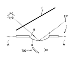
- a display device 700 for a vehicle described in Patent Document 1 is attached in an instrument panel I having an opening H provided in a wall A facing the windshield F, and the opening H Through which the image is projected onto the windshield F.
- a transparent cover C that closes the opening H in order to prevent dust or moisture from entering the opening H may be provided. The light may be reflected by the cover C and head toward the passenger's eye point EP, which may cause discomfort.
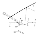
- a vehicle display device 800 shown in FIGS. 5 and 14 is conceivable as a configuration for avoiding that external light travels toward the passenger's eye point EP.
- the vehicle display device 800 is provided in the instrument panel I.
- the instrument panel I has an opening H formed in a wall A facing the windshield F, and a front bezel portion W provided on the front side of the opening H has a front side to a rear side (FIGS. 5 and 14). , A light-transmitting falling wall portion Wa that gradually goes downward as it goes from left to right).
- the opening H is provided with a cover C that gradually moves upward as it goes from the front side to the rear side of the vehicle.
- the vehicle display device 800 projects an image on the windshield F through the opening H.
- the light guide member 802 cannot sufficiently guide light to the vicinity of the descending wall portion Wa, or when the guided light is emitted from the light guide member 802, the descending wall is efficiently provided.
- the falling wall portion Wa may appear darker than the peripheral portion, or may not face the portion Wa.
- the first object of the present invention is to provide a bezel body and a vehicle display device that can effectively suppress discomfort given to the passenger by making the reflection on the windshield less noticeable.
- the end surface (light entrance surface 802a) on the vehicle front side of the light guide member 802 is an instrument. Since it is disposed so as to be exposed from the panel I, dust or the like may enter through a gap between the light guide member 802 and the descending wall portion W, and the light guide function is achieved because dust adheres to the light guide member 802. The amount of light guided to the descending wall W by the light guide member 802 may decrease. Further, for example, external light such as sunlight is incident on the light incident surface 802a of the light guide member 802 from above, so that light incident on the light incident surface 802a enters the lower surface 802b of the light guide member 802.
- the incident angle i becomes small, and there is a possibility that a part of the light is emitted outside the light guide member 802 without being totally reflected on the lower surface 802b.
- the amount of light guided may be reduced.
- induced to the falling wall part W falls, the falling wall part W cannot be brightened so that a light-dark difference may become small, and reflection on the windshield F may not be conspicuous enough. It may not be possible.
- a second object of the present invention is to provide a bezel body that can effectively make the reflection on the windshield inconspicuous, and a vehicle display device including the bezel body.
- the invention described in claim 1 is an image projector that is fitted into a wall facing a windshield in an instrument panel of a vehicle and disposed in the instrument panel.
- a bezel body comprising a bezel member that forms part or all of the periphery of an opening for projecting an image on the windshield, comprising a plate-shaped light guide member, the bezel member being located with respect to the opening
- a front bezel portion disposed on the front side of the vehicle, and the front bezel portion is lifted from the opposite wall so that a front end portion of the vehicle has a gap between the front wall and the opposite wall.
- a light-transmitting descending wall portion that gradually goes downward and reaches the opening as it goes from the front side to the rear side of the vehicle.
- Light that is disposed below the sel part and that enters the front end surface of the vehicle is guided to the descending wall portion, and is changed to a predetermined range on the lower surface on the rear side of the vehicle by changing the path in the plate thickness direction.
- the bezel body is characterized in that a reflecting portion for reflecting the light is formed.
- a diffusion portion that diffuses light emitted upward is formed on the upper surface of the light guide member. is there.
- the invention described in claim 3 is the bezel body according to claim 1 or 2, further comprising a support member that supports the light guide member from below and reflects light from above. It is.
- an image projector disposed in an instrument panel of a vehicle is fitted into a facing wall of a windshield in the instrument panel, and the image projector is imaged on the windshield.
- a vehicle display device comprising: a bezel body having a bezel member that forms a part or all of a peripheral edge of an opening for projecting an object, wherein the bezel body is any one of claims 1 to 3. It is comprised with the bezel body of description, It is a display apparatus for vehicles characterized by the above-mentioned.
- an opening for projecting an image onto the windshield by an image projector that is fitted into a wall facing the windshield of the instrument panel of the vehicle and disposed in the instrument panel.
- a bezel body having a bezel member that forms part or all of the peripheral edge of the vehicle, wherein the bezel member has a front bezel portion disposed on the front side of the vehicle with respect to the opening, and the front bezel portion
- the front end of the vehicle is arranged so as to be lifted from the facing wall so that a gap is formed between the vehicle and the facing wall, and gradually moves downward from the front side to the rear side of the vehicle.
- a light-transmitting descending wall portion that reaches the opening, and the bezel body is formed in a plate shape, and is disposed to overlap the inner surface of the front bezel portion.
- a light window member provided between the light guide member and the light guide member is housed in the housing space with an end face on the front side of the vehicle facing the light window member, and the light window member is
- the bezel body includes a light deflecting portion that deflects light taken from the gap so as to be directed toward an end surface of the light guide member on a front side of the vehicle.
- the invention described in claim 6 is the invention described in claim 5, wherein the daylighting window member has a plate-like window main body portion, and the light deflection portion is an inner surface or an outer surface of the window main body portion. And a plurality of wedge-shaped ridges or grooves extending in the width direction of the vehicle.
- an image projector disposed in an instrument panel of a vehicle is fitted into a facing wall of a windshield in the instrument panel, and the image projector has an image on the windshield.
- the front end portion of the front bezel portion is disposed so as to be lifted so as to leave a gap with the opposing wall, and the light guide member is disposed below the front bezel portion. Since it is provided, outside light irradiated into the vehicle from the front side through the windshield is taken in from the front end surface of the light guide member, and the outside light is guided toward the descending wall portion by the light guide member. Can do. Furthermore, since the reflecting portion is formed in a predetermined range on the rear side of the vehicle on the lower surface of the light guide member, it is easy to reflect upward by changing the path of the guided outside light in the plate thickness direction. The light can be efficiently irradiated from the light guide member toward the descending wall portion. Therefore, the reflection of the descending wall portion on the windshield can be made inconspicuous, and the discomfort given to the passenger can be effectively suppressed.
- the diffusion portion that diffuses light is formed on the upper surface of the light guide member, the light emitted from the upper surface of the light guide member is concentrated at a specific location. It is possible to prevent occurrence of unevenness in the reflection of the descending wall portion on the windshield.
- the support member that supports the light guide member from below reflects light from above, the light emitted downward from the light guide member is reflected and guided again.
- the light returned to the optical member and the light taken into the light guide member can be used effectively. Therefore, it is not necessary to enlarge the front bezel portion in the vertical direction or provide another member in order to increase the amount of light collected.
- the reflection part formed on the light guide member makes the reflection on the windshield of the descending wall part less noticeable as described above, and the discomfort given to the passenger is effective. Can be suppressed.
- the accommodation space of the light guide member opened toward the gap between the opposing wall of the instrument panel and the front bezel portion of the bezel member is defined as the front bezel portion. It is formed between the case part.
- a daylighting window member is provided between the front bezel portion and the case member so as to seal the opening of the housing space and to take light from the gap into the housing space.
- the light guide member is housed in the housing space with the end face on the front side of the vehicle facing the daylighting window member, and the daylighting window member heads the light taken from the gap toward the end face of the light guide member on the front side of the vehicle. In this way, an optical deflecting unit for deflecting is provided.
- the opening of the accommodation space in which the light guide member is accommodated by the daylighting window member is sealed, it is possible to suppress the intrusion of dust into the accommodation space. Since the light taken in from the gap by the light deflector is deflected so as to go to the end face of the light guide member on the front side of the vehicle, the light going to the end face is in a direction orthogonal to or near to the end face. Therefore, the amount of light reaching the end portion on the rear side of the vehicle in the light guide member can be secured. As a result, a decrease in the amount of light guided to the descending wall can be suppressed, the descending wall can be brightened so as to reduce the difference in brightness, and the reflection on the windshield is effectively inconspicuous. Can do.
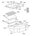
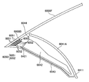
- FIG. 1 is a perspective view showing a vehicle display device according to a first embodiment of the first invention.
- FIG. It is II-II sectional drawing of the said display apparatus for vehicles. It is sectional drawing which expands and shows the principal part of the said display apparatus for vehicles. It is sectional drawing which shows the display apparatus for vehicles of a prior art. It is sectional drawing which shows the display apparatus for vehicles of another prior art. It is a perspective view which shows a mode that the display apparatus for vehicles concerning 2nd Embodiment of 1st invention was assembled
- FIG. 17 is a cross-sectional view taken along the line 2000II-2000II of the vehicle display device of FIG. It is a disassembled perspective view of the display apparatus for vehicles of FIG. (A) is an enlarged sectional view for explaining the progress of light in the light guide member of the vehicle display device of FIG. 16, and (B) is a sectional view taken along the line 2000I-2000I in (A).
- FIG. 17 is a rear perspective view of the light guide member shown in FIG. 16. It is sectional drawing which shows the display apparatus for vehicles of the prior art of 2nd invention. It is sectional drawing which shows the display apparatus for vehicles of the other prior art of 2nd invention.
- FIG. 3 is a cross-sectional view of the vehicle display device taken along line 3000II-3000II. It is an expanded sectional view which expands and shows the principal part of the said display apparatus for vehicles. It is sectional drawing which shows the display apparatus for vehicles of the prior art of 3rd invention. It is sectional drawing which shows the display apparatus for vehicles of the other prior art of 3rd invention. It is a perspective view which shows a mode that the display apparatus for vehicles concerning one Embodiment of 4th invention was assembled
- FIG. 32 is a cross-sectional view of the vehicle display device of FIG. 30 taken along the line 4000II-4000II. It is a disassembled perspective view of the display apparatus for vehicles of FIG.
- FIG. 33A is an enlarged partial cross-sectional view of the vehicle display device of FIG. 32 with the shutter opened
- FIG. 33B is an enlarged partial cross-sectional view of the vehicle display device of FIG. 32 with the shutter closed.
- FIG. 38 is an enlarged cross-sectional view illustrating the progress of light in the vehicle display device of FIG. 37.
- FIG. 38 is an enlarged cross-sectional view illustrating the progress of light in a modification of the vehicle display device of FIG.
- FIG. 38 is an enlarged cross-sectional view for explaining the progress of light in another modification of the vehicle display device of FIG. 37.
- FIG. 2 is a cross-sectional view of the vehicle display device, 6000II-6000II.
- FIG. It is sectional drawing which expands and shows the principal part of the said display apparatus for vehicles.
- the vehicular display device 1 has an opposing wall A between the image projector 2 disposed in the instrument panel I of the vehicle and the windshield F in the instrument panel I.
- An apparatus for projecting the traveling state of the vehicle such as speed and road conditions on the windshield F as an image, for example, with the cover 3 provided in the opening H formed in the cover 3 and the bezel body 4 provided around the cover 3. is there.
- the vehicle front-rear direction, the left-right direction, the front side and the rear side, and the upper side and the lower side in the front-rear direction are as shown in FIGS.
- the image projector 2 includes a projector main body 21 and a mirror 22, and projects an image toward the windshield F through the opening H. At this time, the image projector 2 causes the image to form an image far away from the passenger so that the image can be recognized naturally even when the passenger is focused far away during driving.
- the cover 3 is made of, for example, a transparent resin or glass, and transmits light emitted from the image projector 2 and protects the image projector 2 from dust and moisture. Further, the cover 3 is provided at a position where the front side end 3a is lower than the rear side end 3b (that is, provided at the front lower side), and external light is reflected to reach the eye point EP of the passenger. Is suppressed.
- the bezel body 4 includes a bezel member 41 that forms the periphery of the opening H, a light guide member 42 provided below a front bezel portion 41A described later, and a support member 43 that supports the light guide member 42 from below. .
- the bezel member 41 is made of, for example, a resin having substantially the same color as the facing wall A, and includes a front bezel portion 41A on the front side, a rear bezel portion 41B on the rear side, and a front bezel portion 41A and a rear bezel portion at both ends in the left-right direction.
- the left and right bezel portions 41 ⁇ / b> C provided between the first wall 41 ⁇ / b> B and the opposite wall A are supported, and the cover 3 is supported.
- Each bezel part 41A, 41B, 41C may be formed separately, respectively, and may be formed integrally.
- the front bezel portion 41A is arranged so as to be lifted from the opposing wall A so that a gap between the front bezel portion and the opposing wall A is opened, and gradually opens downward from the front side toward the rear side. It has a descending wall portion 411 that reaches H. That is, the front bezel portion 41 ⁇ / b> A is configured to support the front side end portion 3 a of the cover 3 at the lower end (rear end) of the descending wall portion 411.
- the descending wall portion 411 has light transparency and the upper surface has substantially the same color as the opposing wall A, and transmits light from below upward.
- the transmitted light is transmitted to the upper surface of the opposing wall A and the bezel member 41. It is comprised so that it may become substantially the same color as reflected light.
- the entire front bezel portion 41A may be the descending wall portion 411, or only the portion of the front bezel portion 41A that is difficult to receive external light may be the descending wall portion 411 and the other portions may be configured to be opaque.
- the light guide member 42 is made of a transparent and high refractive index member such as glass or resin, and extends in the front-rear direction between the front bezel portion 41A and the support member 43 as shown in an enlarged view in FIG. It is formed in a plate shape, and is configured such that light incident rearward from the front end surface 421 is totally reflected on the inner side and travels backward. Further, the light guide member 42 is formed so that the plate thickness dimension becomes smaller from the front side toward the rear side.
- a reflection part 422 having a wedge shape in cross section formed by a convex part extending in the left-right direction is formed. Reflection is performed by changing in the plate thickness direction (that is, upward).
- the reflection part 422 should just be formed in the suitable range of the back side at least according to the refractive index, shape, etc. of the light guide member 42, and may be formed in the whole lower surface.
- a fine concavo-convex diffusing portion 423 is formed in a range of the upper surface of the light guide member 42 facing the reflecting portion 422 so that light emitted upward from the light guide member 42 is diffused. Yes. Note that the diffusion portion 423 may be formed on the entire top surface of the light guide member 42.
- the support member 43 is supported by the bezel member 41 while supporting the light guide member 42, and a reflection member 431 is provided on the upper surface so as to reflect light from above. Further, the support member 43 has an end on the front side that is provided at substantially the same height as the upper surface of the opposing wall A, forms a daylighting portion 44 between the front bezel portion 41A on the front side, and windshield F The external light irradiated from the front side through the light can be taken in from the front end surface 421 of the light guide member 42 through the daylighting portion 44.
- the daylighting unit 44 may be provided with a window that transmits light.
- the light emitted from the upper surface is diffused by the diffusing portion 423 toward the upper front bezel portion 41A, and the light emitted from the lower surface is reflected upward by the reflecting member 431 of the support member 43 and is incident on the light guide member 42 again. To do.
- the light traveling in the light guide member 42 toward the rear side reaches the reflecting portion 422 on the lower surface, the light is reflected toward the plate thickness direction, reaches the upper surface, and is emitted while being diffused by the diffusing portion 423. It reflects and proceeds backwards.
- outside light is guided from the front side toward the rear side by the light guide member 42 and is emitted toward the upper front bezel portion 41A.
- the light that has reached the descending wall portion 411 in the front bezel portion 41 ⁇ / b> A passes through the descending wall portion 411 toward the windshield, and is reflected in the descending wall portion 411.
- the reflecting portion 422 is formed in a predetermined range on the rear side of the lower surface of the light guide member 42, the light guided outside light is easily reflected upward, and the falling wall portion from the light guide member 42. Light can be efficiently irradiated toward the region 411. Therefore, it is possible to prevent the descending wall portion 411 from being reflected darkly on the windshield F, and to effectively suppress discomfort given to the passenger by making the reflection inconspicuous.
- the diffusion portion 423 is formed on the upper surface of the light guide member 42, the light emitted from the upper surface of the light guide member 42 is prevented from concentrating on a specific location, and the windshield F of the descending wall portion 411 is protected. It is possible to suppress unevenness in the reflection on the screen.
- the support member 43 includes the reflection member 431, the light taken into the light guide member 42 can be used effectively. Therefore, in order to increase the amount of light collected to the light guide member 42, it is not necessary to enlarge the light collecting portion 44 or the front end surface 421 of the light guide member 42 in the vertical direction.
- the plate thickness dimension of the light guide member 42 decreases from the front side toward the rear side, the light traveling in the light guide member 42 is concentrated in the plate thickness direction (that is, the vertical direction), and the descending wall The light can be easily guided toward the lower end portion of the portion 411, and the reflection of the descending wall portion 411 on the windshield F can be made inconspicuous.
- the present invention is not limited to the above-described embodiment, and includes other configurations and the like that can achieve the object of the present invention, and the following modifications and the like are also included in the present invention.
- the diffusion portion 423 is formed in the range of the upper surface of the light guide member 42 facing the reflection portion 422.
- the diffusion portion is formed on the entire upper surface of the light guide member.
- it may be omitted from the light guide member.
- a diffusion portion may be formed on the lower surface of the descending wall portion.
- the bezel body 4 includes the support member 43 and the support member 43 is provided with the reflection member 431.
- the reflection member is omitted and mirror processing is performed on the upper surface of the support member. It may be configured to reflect light from above. If the lower surface of the light guide member is configured to sufficiently reflect light, the support member may be configured not to reflect light, and the bezel member may be configured to support the light guide member. If it is, the support member may be omitted.
- the thickness of the light guide member 42 is reduced from the front side toward the rear side.
- the light guide member has an appropriate plate thickness and shape and extends in the front-rear direction. Anything is acceptable.
- a bezel body and a vehicle display device according to a second embodiment of the present invention will be described with reference to FIGS.
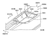
- FIG. 6 is a perspective view showing a state in which the vehicle display device according to the present embodiment is assembled to the instrument panel.
- FIG. 7 is a view of the vehicle display device of FIG. 6 as viewed from the front side of the vehicle.
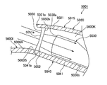
- FIG. 8 is a cross-sectional view of the vehicle display device of FIG.
- FIG. 9 is an exploded perspective view of the vehicle display device of FIG.
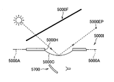
- FIG. 10 is a view for explaining a daylighting window member provided in the vehicle display device of FIG. 6.
- FIG. 11 is an enlarged cross-sectional view for explaining the progress of light in the light guide member of the vehicle display device of FIG. 6 and shows a case where the sun is at a relatively low position.
- FIG. 11 is an enlarged cross-sectional view for explaining the progress of light in the light guide member of the vehicle display device of FIG. 6 and shows a case where the sun is at a relatively low position.
- FIG. 12 is an enlarged cross-sectional view for explaining the progress of light in the light guide member of the vehicle display device of FIG. 6 and shows a case where the sun is at a relatively high position.
- “front / rear / up / down / left / right” corresponds to front / rear, up / down / left / right of the vehicle V.
- the vehicular display device 1 is attached to an instrument panel 1000I of a vehicle 1000V and is used as a head-up display device that projects an image onto a windshield 1000F. Is.
- the vehicle display device 1001 includes an image projector 1010 and a bezel body 1015 as shown in FIGS.
- the image projector 1010 includes a display source 1011 for projecting an image, a reflection unit 1012 that reflects an image from the display source 1011, a synthetic resin casing 1013 that houses the display source 1011 and the reflection unit 1012, and have.
- the housing 1013 includes an upper wall portion 1013a, a lower wall portion 1013b disposed to face the upper wall portion 1013a, and a peripheral wall portion 1013c connected to the peripheral edges of the upper wall portion 1013a and the lower wall portion 1013b.
- the upper wall portion 1013a is provided with an opening 1013d that is disposed so as to overlap with an opening 1020a of a bezel member 1020 described later.
- the image projector 1010 reflects the image projected by the display source 1011 on the reflection unit 1012, and projects the image onto the windshield 1000F through the opening 1013d. Thereby, it is visually recognized as an image displayed on the windshield 1000F by the passenger of the vehicle 1000V.
- the bezel body 1015 includes a bezel member 1020, a light guide member 1030, a support member 1040 as a case member, a daylighting window member 1050, and a cover 1060.
- the bezel member 1020 is made of, for example, a semi-transparent (light transmissive) synthetic resin, and has an annular shape in plan view having an opening 1020a at the center, and has a shape that gradually goes downward from the outer peripheral edge toward the inner peripheral edge. is doing.
- the bezel member 1020 is formed in a shape that is an upside down version of a hollow, substantially square frustum with an upper end surface and a lower end surface.
- the bezel member 1020 is placed in a hole provided in a wall 1000A facing the windshield 1000F of the instrument panel 1000I. That is, the bezel member 1020 is fitted into the opposing wall 1000A and forms the entire periphery of the opening 1020a for the image projector 1010 disposed in the instrument panel 1000I to project an image on the windshield 1000F. .
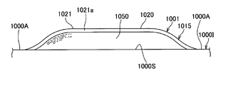
- the bezel member 1020 has a front bezel portion 1021 disposed on the front side of the vehicle 1000V when fitted into the opposing wall 1000A.
- the front bezel portion 1021 is disposed so as to float upward from the opposing wall 1000A so that the front end 1021a of the vehicle 1000V has a gap 1000S between the front bezel portion 1021 and the opposing wall 1000A (that is, with respect to the opposing wall 1000A). Placed above).
- the front bezel portion 1021 has a descending wall portion 1022 that gradually goes downward and reaches the opening 1020a as it goes from the front side to the rear side of the vehicle 1000V.
- the bezel member 1020 When the bezel member 1020 is fitted into the opposing wall 1000A, a part of the front side of the outer peripheral edge of the bezel member 1020 (that is, the front end 1021a of the front bezel portion 1021 of the vehicle 1000V) is lifted above the opposing wall 1000A. (FIG. 7), and other portions of the outer peripheral edge other than the portion are arranged so that the outer surface (upper surface) of the bezel member 1020 and the outer surface of the opposing wall A are smoothly connected (FIG. 6). At this time, the opening 1020a of the bezel member 1020 and the opening 1013d of the image projector 1010 are arranged so as to overlap in the vertical direction. Further, the bezel member 1020 is adjusted to have the same appearance as that of the opposing wall 1000A, for example, so that the difference in reflection on the windshield 1000F from the opposing wall 1000A of the instrument panel 1000I is not noticeable. And surface processing.
- the light guide member 1030 is formed in a substantially rectangular plate shape (FIG. 9) in a plan view using a highly transparent material such as synthetic resin such as glass, acrylic, and polycarbonate, and is formed on the inner surface of the front bezel portion 1021. They are placed one above the other with a slight gap (ie, they are placed along the inner surface of the front bezel portion 1021).
- the light guide member 1030 is formed thick on the front side and thin on the rear side, and the portion between the thickly formed portion and the thinly formed portion is from the front to the rear. It is formed so as to become thinner gradually as it goes to.
- the surface of the light guide member 1030 facing downward is formed in a flat shape, and the surface of the downward wall portion 1022 facing upward is a slope that gradually descends from the front toward the rear in the middle portion in the front-rear direction. A surface is formed.
- the light guide member 1030 is formed so as to guide the light that has entered the light incident surface 1030a, which is the front end surface of the vehicle 1000V, to the rear end portion and to emit light from the surface on the descending wall portion 1022 side.
- the light guide member 1030 guides light in the light guide direction from the front end portion with the light incident surface 1030a toward the opposite rear end portion. Thereby, light can be guided toward the light-transmitting descending wall portion 1022 to illuminate the vicinity of the opening 1020a in the descending wall portion 1022.
- the support member 1040 has a mounting portion 1041 made of synthetic resin and a pair of leg portions 1042.
- the placement portion 1041 is a portion on which the light guide member 1030 is placed, and is formed in a substantially plate shape whose plan view shape is slightly larger than the plan view shape of the light guide member 1030.
- the mounting portion 1041 is disposed at a distance from the inner surface of the front bezel portion 1021, and the front end portion 1041a of the vehicle 1000V is aligned with the end portion 1021a of the front bezel portion 1021 in a generally vertical direction.
- both end portions facing in the left-right direction are disposed in contact with the inner surface of the bezel member 1020.
- the mounting portion 1041 forms an accommodation space 1000 ⁇ / b> K that accommodates the light guide member 1030 between the placement portion 1041 and the front bezel portion 1021.
- the accommodation space 1000K opens toward the gap 1000S.
- the light guide member 1030 is disposed such that the light incident surface 1030a faces the gap 1000S through the opening of the accommodation space 1000K.
- the pair of leg portions 1042 are portions that connect the mounting portion 1041 and the housing 1013 of the image projector 1010, and respectively forward and upward from both left and right ends of the front surface of the peripheral wall portion 1013 c of the housing 1013. It is extended (FIG. 9).
- the base end of the leg portion 1042 is integrally fixed to the housing 1013, and a fixing portion 1041b provided on the lower surface of the placement portion 1041 is fixed to the distal end.
- the lighting window member 1050 is formed by using a highly transparent material such as synthetic resin such as glass, acrylic, and polycarbonate.
- the daylighting window member 1050 is provided so as to seal the opening of the accommodation space 1000K and to take light from the gap 1000S into the accommodation space 1000K.
- the daylighting window member 1050 includes a window main body portion 1051 and a light refraction portion 1052 as a light deflection portion.
- the window main body 1051 is formed in a substantially trapezoidal plate shape (FIGS. 7 and 9) whose plan view is the same as the opening of the accommodation space 1000K.
- the window main body portion 1051 is formed by sealing the front end 1021a of the front bezel portion 1021 and the mounting portion 1041 of the support member 1040 so as to seal (seal) the opening of the accommodation space 1000K in which the light guide member 1030 is accommodated. It arrange
- An outer surface 1051a (surface facing the vehicle front side) of the window main body 1051 is formed in a flat shape, and a light refracting portion 1052 for deflecting light by refraction is provided on the inner surface 1051b (surface facing the vehicle rear side). ing.
- the light refracting portion 1052 is provided on the inner surface 1051b of the window main body portion 1051, and has a plurality of ridges 1053 having a wedge-shaped cross section (prism shape) extending over the entire inner surface 1051b of the window main body portion 1051 in the left-right direction. Yes.
- the plurality of ridges 1053 are arranged in the vertical direction to form a prism pattern.
- the light refracting unit 1052 refracts the light incident on the outer surface 1051a of the window main body 1051 toward the light incident surface 1030a of the light guide member 1030, that is, with respect to the light incident surface 1030a of the light guide member 1030.
- the shape of the ridge 1053 is set so as to be refracted in a direction perpendicular to or perpendicular to the perpendicular direction.
- the light refracting portion 1052 has a plurality of protrusions 1053 having a wedge shape in cross section provided on the inner surface of the window main body portion 1051, but is not limited to this, and the light refracting portion 1052. However, it may be provided on the outer surface 1051a of the window main body 1051 and may be provided with a concave groove having a wedge-shaped cross section instead of a part or all of the ridges 1053.
- all the shapes of the plurality of ridges 1053 may be the same, or a plurality of different shapes (that is, different light refraction directions) ridges 1053 may be provided in a mixed manner.
- the light refracting unit 1052 deflects light by refraction.
- the present invention is not limited to this, and a light diffracting unit that deflects light by diffraction may be provided in place of the light refracting unit 1052.
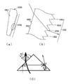
- FIG. 10C schematically shows an example of a path along which light that has entered the prism-shaped translucent member travels. It is considered that the light travels on the same path in the projection 1053 of the daylighting window member 1050.
- the cover 1060 is formed on a thin plate using a highly transparent material such as synthetic resin such as glass, acrylic, or polycarbonate, and is fixed to the periphery of the opening 1020a so as to close the opening 1020a of the bezel member 1020. Attached.
- the cover 1060 is disposed so as to go upward as it goes from the front side to the rear side of the vehicle 1000V (FIG. 8). Thereby, it can suppress that the light which hit the cover 1060 goes directly to a passenger
- the incident angle of the light with respect to the lower surface 1030b is relatively large, the light is totally reflected on the lower surface 1030b and travels toward the rear end of the light guide member 1030. Thereby, the amount of light emitted at the rear side end of the light guide member 1030 can be secured.
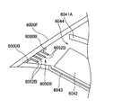
- the accommodation space 1000K of the light guide member 1030 opened toward the gap 1000S between the facing wall 1000A of the instrument panel 1000I and the front bezel portion 1021 of the bezel member 1020 It is formed between the bezel portion 1021 and the mounting portion 1041 of the support member 1040.
- a daylighting window member 1050 is provided between the front bezel portion 1021 and the mounting portion 1041 so as to seal the opening of the accommodation space 1000K and to take light from the gap 1000S into the accommodation space 1000K.
- the light guide member 1030 is accommodated in the accommodation space 1000K with the light incident surface 1030a facing the daylighting window member 1050, and the light that the daylighting window member 1050 has taken in from the gap 1000S is the light incident surface 1030a of the light guide member 1030.
- a light refracting portion 1052 that refracts the light toward the head. Since it did in this way, since the opening of the accommodation space 1000K in which the light guide member 1030 is accommodated is sealed by the daylighting window member 1050, the entrance of dust into the accommodation space 1000K can be suppressed.
- the light taken from the gap 1000S is refracted by the light refracting portion 1052 of the daylighting window member 1050 so as to be directed toward the light incident surface 1030a of the light guide member 1030. Therefore, the light toward the light incident surface 1030a is incident on the light incident surface 1030a.
- the light travels in a direction orthogonal to or close to the orthogonal direction, so that the amount of light reaching the rear end of the vehicle 1000V in the light guide member 1030 can be secured. Thereby, the fall of the quantity of the light guide
- the daylighting window member 1050 has a plate-like window main body portion 1051, and the light refracting portion 1052 has a plurality of cross-sectional wedge shapes extending in the width direction of the vehicle 1000 V provided on the inner surface 1051 b of the window main body portion 1051.
- the ridge 1053 is provided. Since it did in this way, while being able to comprise the light refracting part 1052 by a simple shape, the refractive direction of light can be easily adjusted by changing the cross-sectional shape of the protruding item
- the present invention has been described with reference to a preferred embodiment, but the bezel body and the vehicle display device of the present invention are not limited to the configuration of the above embodiment.
- the bezel member 1020 is formed in an annular shape in plan view and has the front bezel portion 1021, but is not limited thereto.
- the bezel member 1020 is configured by only the front bezel portion 1021, only the periphery of the opening 1020a on the front side of the vehicle 1000V is formed, and the remaining periphery of the opening 1020a is formed by the opposing wall of the instrument panel 1000I. Also good.
- the entire bezel member 1020 is formed of a light-transmitting synthetic resin.
- the configuration is not limited thereto, and at least the descending wall portion 1022 is light-transmitting. Good.
- a vehicle display device as a head-up display device that projects an image onto a windshield of a vehicle is provided in an instrument panel (see, for example, Japanese Patent Application Laid-Open No. 2007-148092).
- the vehicle display device 2700 described in this patent document is mounted in an instrument panel 2000I having an opening 2000H provided on a wall 2000A facing the windshield 2000F, and the front display through the opening 2000H.
- An image is projected onto the glass 2000F.
- a transparent cover 2000C that closes the opening 2000H may be provided in order to prevent dust or moisture from entering the opening H.
- the light may be reflected by the cover 2000C and head toward the passenger's eye point 2000EP, which may cause discomfort.
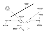
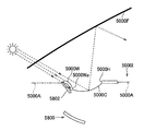
- a vehicle display device 2800 shown in FIG. 23 is conceivable as a configuration for avoiding that external light travels toward the passenger's eye point 2000EP.
- the vehicle display device 2800 is provided in the instrument panel 2000I.
- the instrument panel 2000I has an opening 2000H formed on a wall 2000A facing the windshield 2000F, and a front bezel portion 2000W provided on the front side of the opening 2000H extends from the front side to the rear side (left side in FIG. 23).
- a light-transmitting descending wall portion 2000Wa that gradually goes downward as it goes from side to side) is formed.
- the opening 2000H is provided with a cover 2000C that gradually moves upward as it goes from the front side to the rear side of the vehicle.
- the vehicle display device 2800 projects an image onto the windshield 2000F through the opening 2000H.
- the descending wall portion 2000Wa is provided and the vehicle front side of the cover 2000C is located below the rear side, it is possible to make it difficult for outside light to reach the cover 2000C, and for the cover 2000C. It can suppress that the reflected external light goes to a passenger's eyepoint 2000EP.
- the distance between the upper surface of the light guide member 2802 and the lower surface of the descending wall portion 2000Wa is uniform. Not. For this reason, the light incident on the descending wall portion 2000Wa from the light guide member 2802 is also not uniform, and there is a problem that color unevenness occurs in the descending wall portion 2000Wa.
- An object of the present invention is to provide a bezel body and a vehicle display device which can effectively suppress discomfort given to a passenger by making the reflection on the windshield less noticeable.
- the invention ⁇ 1 ⁇ of the present invention is fitted into an instrument panel of a vehicle, and an image projector disposed in the instrument panel projects an image on a windshield.
- a bezel member that forms part or all of the periphery of the opening for the plate, and a plate-like light guide member that is disposed below the front bezel portion of the bezel member that is disposed on the front side of the vehicle with respect to the opening.
- the front bezel portion is disposed above the instrument panel so that a front end of the vehicle has a gap between the instrument panel and the rear side of the vehicle.
- a light-transmitting descending wall portion provided so as to gradually go downward and reach the opening as it goes to the light guide member, and the light guide member enters from the gap
- a bezel body characterized in that the upper surface has a shape along the lower surface of the descending wall.
- a reflecting portion that reflects light by changing a course in a plate thickness direction of the light guide member is formed in a predetermined range on the rear side of the vehicle on the lower surface of the light guide member. It is a bezel body as described in the invention ⁇ 1 ⁇ .
- the invention ⁇ 3 ⁇ is the bezel body according to the invention ⁇ 1 ⁇ or ⁇ 2 ⁇ , comprising a brightness enhancement film disposed on the upper surface of the light guide member and formed by arranging a plurality of prisms. .
- the invention ⁇ 4 ⁇ includes a brightness enhancement film that is arranged on the upper surface of the light guide member and is formed by arranging a plurality of prisms extending along the front-rear direction of the vehicle, and the vehicle on the lower surface of the light guide member
- the bezel body according to the invention ⁇ 1 ⁇ characterized in that a reflecting portion in which a plurality of prisms extending in the left-right direction of the vehicle are arranged in a predetermined range on the rear side of the vehicle.
- the invention ⁇ 5 ⁇ includes an image projector disposed in an instrument panel of a vehicle, and a part of a periphery of an opening that is fitted in the instrument panel and the image projector projects an image on a windshield or
- a display device for a vehicle comprising a bezel body having a bezel member forming the whole, wherein the bezel body is constituted by the bezel body according to any one of the inventions ⁇ 1 ⁇ to ⁇ 4 ⁇ . It is the display apparatus for vehicles characterized by these.
- the front end portion of the front bezel portion is disposed above the instrument panel so that a gap is formed between the front bezel portion and the light guide member. Since it is provided below the front bezel portion, the light guide member can guide the light incident from the gap through the windshield to illuminate the descending wall portion. Furthermore, since the upper surface of the light guide member is shaped along the lower surface of the descending wall portion, the distance between the upper surface of the light guide member and the lower surface of the descending wall portion is uniform, and color unevenness of the descending wall portion can be suppressed. . Therefore, the reflection of the descending wall portion on the windshield can be made inconspicuous, and the discomfort given to the passenger can be effectively suppressed.
- the reflecting portion is formed in the predetermined range on the lower surface of the light guide member on the rear side of the vehicle so as to change the course in the plate thickness direction of the light guide member and reflect the light. Therefore, the external light can be easily reflected toward the descending wall portion, and light can be efficiently irradiated from the light guide member toward the descending wall portion. Therefore, the reflection of the descending wall portion on the windshield can be made more inconspicuous, and the discomfort given to the passenger can be effectively suppressed.
- the brightness enhancement film formed by arranging a plurality of prisms is arranged on the upper surface of the light guide member, light is more efficiently emitted from the light guide member toward the descending wall portion. Can be irradiated.
- a brightness enhancement film formed by arranging a plurality of prisms extending along the front-rear direction of the vehicle is disposed on the upper surface of the light guide member.
- FIG. 16 is a perspective view illustrating a state in which the vehicle display device according to the embodiment of the present invention is assembled to the instrument panel.
- FIG. 17 is a view of the vehicle display device of FIG. 16 as viewed from the front side of the vehicle.
- 18 is a cross-sectional view of the vehicle display device of FIG. 16 taken along the line 2000II-2000II.
- FIG. 19 is an exploded perspective view of the vehicle display device of FIG. 20A is an enlarged cross-sectional view for explaining the progress of light in the light guide member of the vehicle display device shown in FIG. 16, and
- FIG. 20B is a cross-sectional view taken along the line 2000I-2000I in FIG.
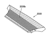
- FIG. 22 is a rear perspective view of the light guide member shown in FIG. 16.
- the vehicle display device 2001 of this embodiment is attached to an instrument panel 2000I of a vehicle 2000V and is used as a head-up display device that projects an image onto a windshield 2000F. Is.
- the front-rear direction, the left-right direction, the front side and the rear side in the front-rear direction, and the upper and lower sides of the vehicle 2000V in the present embodiment are as shown in FIGS.
- the vehicle display device 2001 includes an image projector 2010 disposed in the instrument panel 2000I of the vehicle 2000V, and a bezel body 2015 disposed in the instrument panel 2000I. I have.
- the image projector 2010 includes a display source 2011 for projecting an image, a reflection unit 2012 that reflects an image from the display source 2011, and a synthetic resin that houses the display source 2011 and the reflection unit 2012. And a housing 2013 made of steel.
- the housing 2013 includes an upper wall portion 2013a, a lower wall portion 2013b disposed to face the upper wall portion 2013a, and a peripheral wall portion 2013c connected to the peripheral edges of the upper wall portion 2013a and the lower wall portion 2013b.
- the upper wall portion 2013a is provided with an opening 2013d that is disposed so as to overlap an opening 2020a of a bezel member 2020 described later.
- the image projector 2010 reflects the image projected by the display source 2011 by the reflection unit 2012 and projects the image onto the windshield 2000F through the opening 2013d. Thereby, the passenger of the vehicle 2000V can be visually recognized as an image displayed on the windshield 2000F.
- the bezel body 2015 includes a bezel member 2020, a light guide member 2030, a brightness enhancement film 2040, a support member 2050 as a case member, and a cover 2060. .
- the bezel member 2020 is made of, for example, a semi-transparent (light transmissive) synthetic resin and has an annular shape in plan view having an opening 2020a at the center.
- the bezel member 2020 is provided so as to be gradually lowered as it goes from the outer peripheral edge to the inner peripheral edge, and to be inclined so that its inclination increases as it approaches the inner peripheral edge.
- the bezel member 2020 is fitted into a hole provided in the instrument panel 2000I, and the image projector 2010 arranged in the instrument panel 2000I covers the entire periphery of the opening 2020a for projecting an image onto the windshield 2000F. Forming.
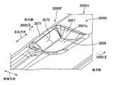
- the front bezel portion 2021 disposed on the front side of the vehicle 2000V with respect to the opening 2020a in the bezel member 2020 includes the instrument 20001 so that a gap 2000S is formed between the front end 2021a of the vehicle 2000V and the instrument panel 2000I. Arranged above panel 2000I. Further, the front bezel portion 2021 has a descending wall portion 2022 that is curved so that the slope gradually increases downward toward the opening 2020a as it goes from the front side to the rear side of the vehicle 2000V, and the inclination increases as it approaches the opening 2020a. Have.
- a portion of the front side of the outer peripheral edge of the bezel member 2020 (that is, the front side end portion 2021a of the vehicle 2000V of the front bezel portion 2021) is more than the instrument panel 2000I. It arrange
- the opening 2020a of the bezel member 2020 and the opening 2013d of the image projector 2010 are arranged so as to overlap in the vertical direction.
- the bezel member 2020 is subjected to, for example, the adjustment of color and surface processing similar to the instrument panel 2000I in order to prevent the difference in the reflection of the instrument panel 2000I on the windshield 2000F from being noticeable. Has been done.
- the light guide member 2030 is formed in a substantially rectangular plate shape in a plan view (FIG. 19) using a material with high transparency such as synthetic resin such as glass, acrylic, and polycarbonate.
- the light guide member 2030 is disposed below the front bezel portion 2021, and guides light incident from the gap 2000S described above to illuminate the front bezel portion 2021 (that is, the descending wall portion 2022). As shown in FIG. 20, the light guide member 2030 is formed so that the plate thickness dimension decreases from the front side toward the rear side.
- the upper surface of the light guide member 2030 is provided in a shape along the lower surface of the front bezel portion 2021 having the descending wall portion 2022. More specifically, like the lower surface of the front bezel portion 2021, the upper surface of the light guide member 2030 gradually moves downward as it goes from the front side to the rear side in the vehicle 2000V, and the inclination increases as it approaches the rear side. Curved and provided. Further, the distance between the upper surface of the light guide member 2030 and the lower surface of the descending wall 2022 is made as small as possible.
- a reflecting portion 2030b in which a plurality of prisms having a wedge-shaped cross section extending in the left-right direction of the vehicle 2000V is formed in a predetermined range on the rear side of the lower surface of the light guide member 2030.
- the plurality of prisms of the reflection unit 2030b are arranged along the front-rear direction of the vehicle 2000V.
- the light reaching the reflecting portion 2030b is reflected by changing the path in the thickness direction of the light guide member 2030.
- the reflection part 2030b should just be formed in the suitable range of the back side at least according to the refractive index, shape, etc. of the light guide member 2030, and may be formed in the whole lower surface.
- the brightness enhancement film 2040 is attached to the upper surface of the light guide member 2030.
- the brightness enhancement film 2040 is formed by arranging a plurality of wedge-shaped fine prisms arranged in the front-rear direction of the vehicle 2000V on the upper surface thereof.
- the plurality of prisms of the brightness enhancement film 2040 are arranged along the left-right direction of the vehicle 2000V. Light that enters from the lower surface of the brightness enhancement film 2040 and exits from the upper surface is refracted by changing the path in the thickness direction of the light guide member 2030.
- the support member 2050 is disposed below the light guide member 2030 and supports the light guide member 2030.
- a glossy reflective portion 2051 is provided so as to reflect light from above.
- the support member 2050 is disposed such that the front end portion is provided at substantially the same height as the top surface of the instrument panel 2000I, and the front end surface 2030a of the light guide member 2030 is opposed to the gap 2000S. Yes. Thereby, the external light irradiated from the front side through the windshield 2000F can be taken in from the front end surface 2030a of the light guide member 2030 through the gap 2000S.
- the support member 2050 is fixed to a pair of leg portions 2013e protruding forward from the peripheral wall portion 2013c of the housing 2013.
- the cover 2060 is formed in a thin plate shape using a highly transparent material such as synthetic resin such as glass, acrylic, or polycarbonate, and is fixed to the periphery of the opening 2020a so as to close the opening 2020a of the bezel member 2020. Attached.
- the cover 2060 is disposed so as to go upward as it goes from the front side to the rear side of the vehicle 2000V (FIG. 18). Thereby, it can control that the light which hits cover 2060 goes directly to a passenger's eyepoint.
- the light emitted from the lower surface is reflected upward by the reflection portion 2051 of the support member 2050 and is incident on the light guide member 2030 again.
- the light traveling backward in the light guide member 2030 reaches the reflection part 2030b on the lower surface, it is reflected by the prism of the reflection part 2030b as shown in FIG. And is emitted from the upper surface.
- outside light is guided from the front side to the rear side by the light guide member 2030 and is emitted toward the upper front bezel portion 2021.
- the light that reaches the descending wall 2022 in the front bezel portion 2021 passes through the descending wall 2022 and is reflected in the descending wall 2022 toward the windshield 2000F.
- the front end 2021a of the front bezel portion 2021 is disposed above the instrument panel 2000I so as to leave a gap 2000S between the front bezel portion 2021 and the light guide member. Since 2030 is provided below the front bezel portion 2021, the light guide member 2030 can guide the light incident from the gap 2000S through the windshield 2000F to illuminate the descending wall 2022. Furthermore, since the upper surface of the light guide member 2030 is shaped along the lower surface of the descending wall portion 2022, the distance between the upper surface of the light guide member 2030 and the lower surface of the descending wall portion 2022 is uniform, and the uneven color of the descending wall portion 2022 is uneven. Can be suppressed.
- the reflection of the descending wall 2022 on the windshield 2000F can be made inconspicuous, and the discomfort given to the passenger can be effectively suppressed.
- the distance between the upper surface of the light guide member 2030 and the lower surface of the descending wall portion 2022 is as small as possible, loss of light from the light guide member 2030 toward the descending wall portion 2022 in the air can be suppressed.
- the reflecting portion 2030b that reflects the light guide member 2030 by changing the path in the thickness direction of the light guide member 2030 is formed in a predetermined range on the lower surface of the light guide member 2030 on the rear side of the vehicle 2000V. Therefore, the guided outside light can be easily reflected toward the descending wall 2022, and light can be efficiently emitted from the light guide member 2030 toward the descending wall 2022. Therefore, the reflection of the descending wall 2022 on the windshield 2000F can be made more inconspicuous, and the discomfort given to the passenger can be effectively suppressed.
- the brightness enhancement film 2040 in which a plurality of prisms are arranged is arranged on the upper surface of the light guide member 2030, the light guide member 2030 is directed toward the descending wall 2022. Light can be irradiated even more efficiently.
- the prism of the reflecting portion 2030b extends in the left-right direction of the vehicle 2000V
- the prism of the brightness enhancement film 2040 extends in the front-rear direction of the vehicle 2000V. That is, the extending direction of the prism of the brightness enhancement film 2040 is a direction rotated by 90 ° with respect to the extending direction of the prism of the reflecting portion 2030b.
- the path of light spreading in the front-rear direction by the reflecting portion 2030b can be changed in the plate thickness direction (FIG. 20A), and the path of light spreading in the left-right direction by the brightness enhancement film 2040 can be changed in the plate thickness direction ( FIG. 20 (B)). Therefore, the light spreading in the left-right direction and the front-rear direction of the vehicle can be efficiently irradiated toward the descending wall 2022 by changing the course in the plate thickness direction of the light guide member.
- the reflection part 2030b and the brightness enhancement film 2040 were provided in the light guide member 2030, it is not restricted to this.
- the light guide member 2030 only needs to have a shape in which the upper surface is along the lower surface of the descending wall 2022, and it is not necessary to provide the reflective portion 2030 b or the brightness increasing film 2040, or any of the reflecting portion 2030 b and the brightness increasing film 2040. Only one of them may be provided.
- the prism of the brightness enhancement film 2040 is provided along the front-rear direction, but the present invention is not limited to this. You may provide along the left-right direction.
- the bezel member 2020 is formed in an annular shape in plan view, and the front bezel portion 2021 is a part of the bezel member 2020.
- the present invention is not limited to this.
- the bezel member 2020 may be configured by only the front bezel portion 2021, and only the periphery of the opening 2020a on the front side of the vehicle 2000V may be formed, and the remaining periphery of the opening 2020a may be formed by the instrument panel 2000I.
- the entire bezel member 2020 is formed of a light-transmitting synthetic resin.
- the present invention is not limited to this, and at least the descending wall 2022 is light-transmitting. I just need it.
- a vehicle display device as a head-up display device that projects an image onto a windshield of a vehicle is provided in an instrument panel (see, for example, Japanese Patent Application Laid-Open No. 2007-148092).
- the vehicle display device 3700 described in this patent document is mounted in an instrument panel 3000I having an opening 3000H provided in a wall 3000A facing the windshield 3000F, and the front display through the opening 3000H.
- An image is projected onto the glass 3000F.
- a transparent cover 3000C that closes the opening 3000H may be provided to prevent dust or moisture from entering the opening 3000H. The light may be reflected by the cover 3000C and head toward the passenger's eye point 3000EP, which may cause discomfort.
- a vehicle display device 3800 shown in FIG. 29 is conceivable as a configuration for avoiding that external light travels toward the passenger's eye point 3000EP.
- the vehicle display device 3800 is provided in the instrument panel 3000I.
- an opening 3000H is formed in a wall 3000A facing the windshield 3000F, and a front bezel portion 3000W provided on the front side of the opening 3000H extends from the front side to the rear side (left side in FIG. 29).
- a light-transmitting descending wall portion 3000Wa is formed that gradually goes downward as it goes from side to side.
- the opening 3000H is provided with a cover 3000C that gradually moves upward as it goes from the front side to the rear side of the vehicle.
- the vehicle display device 3800 projects an image onto the windshield 3000F through the opening 3000H.
- the descending wall portion 3000Wa is provided and the vehicle front side of the cover 3000C is positioned below the rear side, it is possible to make it difficult for outside light to reach the cover 3000C. It can suppress that the reflected external light goes to a passenger's eyepoint 3000EP.
- An object of the present invention is to provide a bezel body and a vehicle display device which can effectively suppress discomfort given to a passenger by making the reflection on the windshield less noticeable.
- the invention ⁇ 6 ⁇ of the present invention which has been made to solve the above-described problems, is placed in an instrument panel of a vehicle, and is mounted on a board on which a display source for generating display light is mounted, and the instrument panel.
- a bezel member that forms part or all of the periphery of the opening for projecting the display light from the display source onto the windshield, and the bezel member is disposed on the front side of the vehicle with respect to the opening.
- the vehicle display device includes a light-transmitting descending wall portion provided so that the forward bezel portion formed is gradually lowered toward the opening toward the rear side of the vehicle, and the descending wall A first light guide member disposed below the light source, a light source mounted on the substrate, and a second light guide member that guides light from the light source to the first light guide member.
- Preparation A vehicle display device, characterized in that the.
- the invention ⁇ 7 ⁇ is the invention ⁇ 6 ⁇ , further comprising: an illuminance sensor that detects external illuminance; and an adjustment unit that adjusts the luminance of the light source based on a detection result of the illuminance sensor. It is a display apparatus for vehicles of description.
- the front bezel portion is disposed above the instrument panel so that a front end of the vehicle has a gap between the instrument panel and the first guide.
- the optical member guides light incident from the gap to illuminate the descending wall portion and guides light incident from the second light guiding member to illuminate the descending wall portion.
- the light from the light source is guided by the second light guide member to the first light guide member disposed below the descending wall portion of the bezel member.
- the guided light is emitted toward the descending wall by the first light guide member, and the descending wall can be illuminated.
- the light source can be mounted on the substrate on which the display source is mounted, and it is not necessary to separately provide the display source substrate and the light source substrate. Therefore, the reflection of the descending wall portion on the windshield can be made inconspicuous at low cost, and the discomfort given to the passenger can be effectively suppressed.
- the reflection on the windshield is more inconspicuous and the discomfort given to the passenger is effectively reduced. Can be suppressed.
- the front end portion of the front bezel portion is disposed above the instrument panel so as to leave a gap between the front bezel portion and the first light guide member is disposed forward. Since it is provided below the bezel portion, outside light irradiated into the vehicle from the front side through the windshield is taken in from the front end surface of the first light guide member, and the outside light is taken into the first guide.
- the light member can irradiate the falling wall portion. Thereby, the reflection can be further made inconspicuous by combining with the light from the light source.
- FIG. 24 is a perspective view showing a vehicle display device according to an embodiment of the present invention.
- FIG. 25 is a view of the vehicle display device of FIG. 24 as viewed from the front side of the vehicle.
- FIG. 26 is a cross-sectional view of the vehicular display device taken along line 3000II-3000II.
- FIG. 27 is an enlarged cross-sectional view showing an essential part of the vehicle display device.
- the vehicle display device 3001 of this embodiment is attached to the instrument panel 3000I of the vehicle 3000V and used as a head-up display device that projects an image onto the windshield 3000F. Is.
- the left-right direction, the front-back direction, and the upper direction and the downward direction be as showing in FIG.24 and FIG.26.
- the vehicle display device 3001 reflects the light from the substrate 3003 on which the display device 3002 as a display source for generating display light is mounted and the display device 3002 to project it onto the windshield 3000F.
- the vehicle display device 3001 includes a bezel member 3007 that is fitted into the instrument panel 3000I and forms the entire periphery of the opening 3007a for projecting the display light from the display device 3002 onto the windshield 3000F, and the opening 3007a.
- the light guide member 3011 and the illuminance sensor 3012 are provided.
- the substrate 3003 is mounted with the display device 3002 and the light source 3010, and is disposed in the housing 3006 so that the display device 3002 and the light source 3010 are directed obliquely upward on the rear side of the vehicle 3000V.
- the folding mirror 3004 reflects display light from the display device 3002 toward the aspherical mirror 3005.
- the aspherical mirror 3005 reflects the light from the folding mirror 3004 so as to travel toward the windshield 3000F through the opening 3007a. Thereby, it is visually recognized as an image displayed on windshield 3000F by a passenger of vehicle 3000V.
- the housing 3006 includes an upper wall portion 3006a, a lower wall portion 3006b disposed opposite to the upper wall portion 3006a, and a peripheral wall connected to the peripheral edges of the upper wall portion 3006a and the lower wall portion 3006b.
- Part 3006c, and case part 3006e which protrudes from the upper end of front peripheral wall part 3006d arranged in the front side of vehicle 3000V among peripheral wall parts 3006c.
- the upper wall portion 3006a has an opening 3006f disposed in the center of the upper wall portion 3006a so as to overlap with an opening 3007a of a bezel member 3007 described later, and an opening for passing a second light guide member 3011 described later provided at the front end. 3006 g are provided.
- the front peripheral wall portion 3006d is provided with an opening 3006h for fitting the substrate 3003 on the lower side thereof.
- the front peripheral wall portion 3006d is formed so as to gradually move forward as it goes upward, and supports a second light guide member 3011 described later from below.
- the case portion 3006e is also formed so as to gradually move forward as it goes upward, and supports a first light guide member 3009 described later.
- the front end portion 3006e1 of the case portion 3006e is provided to be substantially the same height as the upper surface of the instrument panel 3000I.
- the bezel member 3007 is made of, for example, a semi-transparent (light transmissive) synthetic resin and has an annular shape in plan view having an opening 3007a at the center. Further, the bezel member 3007 is provided so as to be gradually lowered as it goes from the outer peripheral edge toward the inner peripheral edge, and to be inclined so as to increase in inclination as it approaches the inner peripheral edge.
- the bezel member 3007 is fitted into a hole provided in the instrument panel 3000I, and the display device 3002 disposed in the instrument panel 3000I forms the entire periphery of the opening 3007a for projecting an image onto the windshield 3000F. is doing.
- the front bezel portion 3071 disposed on the front side of the vehicle 3000V with respect to the opening 3007a is arranged so that the end portion 3071a on the front side of the vehicle 3000V forms a gap 3000S with the instrument panel 3000I. Arranged above panel 3000I. Further, the front bezel portion 3071 has a descending wall portion 3072 that is curved so that its inclination gradually increases toward the opening 3007a as it goes from the front side to the rear side of the vehicle 3000V, and the inclination increases as it approaches the opening 3007a. Have.
- a part of the front side of the outer peripheral edge of the bezel member 3007 (that is, the end 3071a of the front bezel portion 3071 on the front side of the vehicle 3000V) is more than the instrument panel 3000I. It arrange
- the opening 3007a of the bezel member 3007 and the opening 3006f of the housing 3006 housing the display device 3002 are arranged so as to overlap each other in the vertical direction.
- the bezel member 3007 is subjected to, for example, the adjustment of the color and the surface processing similar to the instrument panel 3000I in order to prevent the difference in the reflection of the instrument panel 3000I from being reflected on the windshield 3000F. Has been done.
- the cover 3008 is formed in a thin plate shape using a highly transparent material such as synthetic resin such as glass, acrylic, and polycarbonate, and is fixed to the periphery of the opening 3007a so as to close the opening 3007a of the bezel member 3007. Is provided.
- the cover 3008 is arranged so as to go upward as it goes from the front side to the rear side of the vehicle (FIG. 26). Thereby, it can suppress that the light which hit the cover 3008 goes directly to a passenger
- the first light guide member 3009 is formed in a substantially rectangular plate shape in plan view using a material with high transparency such as synthetic resin such as glass, acrylic and polycarbonate.
- the first light guide member 3009 is disposed below the front bezel portion 3071, guides the light incident from the gap 3000S described above, and irradiates the light toward the front bezel portion 3071 (that is, the descending wall portion 3072). Illuminate.
- the first light guide member 3009 is formed with a thick front portion and a thin rear portion in a cross-sectional view in the front-rear direction (FIG. 27), and a portion between the thick portion and the thin portion. Is formed so that it gradually becomes thinner from the front to the rear.
- the downwardly facing surface of the first light guide member 3009 is formed in a flat shape, and the upwardly facing surface is an intermediate surface in the front-rear direction, and an inclined surface that gradually descends from the front toward the rear. Is formed.
- the first light guide member 3009 is supported on the lower side by the above-described case part 3006e and on the rear side above the case part 3006e. As described above, the front end 3006e1 of the case 3006e is provided at substantially the same height as the upper surface of the instrument panel 3000I, and the front end 3009a of the first light guide member 3009 faces the gap 3000S. Are arranged to be. Accordingly, external light irradiated from the front side through the windshield 3000F can be taken from the front end surface 3009a of the first light guide member 3009 through the gap 3000S. The first light guide member 3009 guides the external light taken from the end surface 3009 a to the rear side and emits light toward the descending wall portion 3072.
- the second light guide member 3011 is formed in a plate shape using a highly transparent material such as a synthetic resin such as glass, acrylic, or polycarbonate.
- the second light guide member 3011 is formed to gradually move forward along the case portion 3006e and the front peripheral wall portion 3006d.
- An incident portion 3011 a that protrudes toward the light source 3010 on the substrate 3003 is provided at the rear end portion of the second light guide member 3011. Light from the light source 3010 is incident on the second light guide member 3011 from the incident portion 3011a.
- a reflection surface 3011b that reflects light incident from the incident portion 3011a toward the front is provided.
- the front end portion of the second light guide member 3011 is disposed between the case portion 3006e and the first light guide member 3009, and the light reflected forward by the reflective surface 3011b is the first.
- a light shielding portion 3011 c is formed in a portion excluding a portion overlapping the reflective surface 3011 b and the lower surface of the first light guide member 3009, and light leakage to the display device 3002 side prevent.
- the illuminance sensor 3012 is a sensor that detects external illuminance, and is installed on the instrument panel 3000I in front of the vehicle 3000V.
- a control unit (not shown) as a control unit for controlling the luminance of the light source 3010 is mounted on the substrate 3003, and a detection result from the illuminance sensor 3012 is input to the control unit. Based on the detection result from the illuminance sensor 3012, for example, the control unit controls to increase the luminance of the light source 3010 if the outside is bright, and decrease the luminance of the light source 3010 if the outside is dark.
- the external light incident from the gap 3000S through the windshield 3000F enters the first light guide member 3009 from the front end surface 3009a.
- the light is emitted from the upper surface or the lower surface when the incident angle is smaller than a predetermined value, and when the incident angle is equal to or larger than the predetermined value, the light is totally reflected to enter the first light guide member 3009. Proceed toward the rear side.
- the light emitted from the upper surface is directed to the upper front bezel portion 3071, and the light emitted from the lower surface is reflected by the case portion 3006e and enters the first light guide member 3009 again. Accordingly, it is possible to secure the amount of light that goes out at the rear side end of the first light guide member 3009.
- the light emitted from the light source 3010 is incident on the second light guide member 3011 from the incident portion 3011a and is reflected forward by the reflecting surface 3011b.
- the light reflected by the reflecting surface 3011b reaches the upper surface, when the incident angle is equal to or greater than a predetermined value, the light is totally reflected to the first light guide member 3009 side, that is, the front side of the second light guide member 3011. Proceed toward.
- the incident angle of the light reaching the upper surface is smaller than a predetermined value, the light is absorbed or reflected by the light shielding portion 3011c and is incident on the second light guide member 3011 again.
- the light reflected by the reflecting surface 3011b reaches the lower surface, when the incident angle is equal to or greater than a predetermined value, the light is totally reflected and is reflected on the first light guide member 3009 side, that is, the second light guide member 3011. Proceed toward the front side of the.
- the incident angle of the light reaching the lower surface is smaller than a predetermined value, it is reflected by the front peripheral wall portion 3006d and is incident on the first light guide member 3009 again. Therefore, the light emitted from the light source 3010 is guided by the second light guide member 3011 and is incident on the rear end side of the first light guide member 3009.
- the light incident on the rear end side of the first light guide member 3009 advances from the upper surface of the first light guide member 3009 to the front bezel portion while proceeding forward while totally reflecting the upper surface or the lower surface as in the case of external light. It is emitted toward 3071.
- light from the light source 3010 is guided by the second light guide member 3011 to the first light guide member 3009 disposed below the descending wall portion 3072 of the bezel member 3007.
- the guided light can be emitted toward the descending wall portion 3072 by the first light guide member 3009.
- the light source 3010 can be mounted on the substrate 3003 on which the display device 3002 is mounted, and it is not necessary to provide the substrate 3003 for the display device 3002 and the substrate 3003 for the light source 3010 separately. Therefore, the reflection of the descending wall portion 3072 on the windshield 3000F can be made inconspicuous at low cost, and the discomfort given to the passenger can be effectively suppressed.
- a control unit mounted on the substrate 3003 adjusts the luminance of the light source 3010 based on the detection result of the illuminance sensor 3012.
- the front end portion 3071a of the front bezel portion 3071 is disposed above the instrument panel 3000I so as to open a gap 3000S between the front bezel portion 3071 and the instrument panel 3000I. Since one light guide member 3009 is provided below the front bezel portion 3071, external light radiated from the front side into the vehicle through the windshield 3000F from the front side is end face 3009a on the front side of the first light guide member 3009. And the outside light can be emitted toward the descending wall portion 3072 by the first light guide member 3009. Thereby, by combining with the light from the light source 3010, the reflection can be made more inconspicuous.
- the gap 3000S is opened between the front end 3071a of the front bezel portion 3071 and the instrument panel 3000I, and external light is incident on the first light guide member 3009.
- the external light may not be incident on the first light guide member 3009 without providing the gap 3000S.
- the first light guide member 3009 and the second light guide member 3011 are provided separately, but the present invention is not limited to this. It is also conceivable to provide the first light guide member 3009 and the second light guide member 3011 integrally. In this case, the front portion disposed on the lower side of the front bezel portion 3071 is the first light guide member 3009, and the rear portion where the front bezel portion 3071 is not disposed is the second light guide member 3011.
- the case portion 3006e is integrally formed with the housing 3006, but is not limited thereto.
- the case portion 3006e may be provided separately from the housing 3006 and fixed to the housing 3006.
- the bezel member 3007 is formed in an annular shape in plan view and has the front bezel portion 3071, but is not limited thereto.
- only the front bezel portion 3071 of the bezel member 3007 may be formed, and only the peripheral edge of the opening 3007a on the front side of the vehicle 3000V may be formed, and the remaining peripheral edge of the opening 3007a may be formed by the instrument panel 3000I.
- the entire bezel member 3007 is formed of a light-transmitting synthetic resin, but is not limited thereto. It is sufficient that at least the descending wall portion 3072 is light transmissive.
- the luminance of the light source 3010 is controlled according to the detection result of the illuminance sensor 3012.
- the present invention is not limited to this. For example, when the light switch is not turned on, the brightness of the light source 3010 is determined to be bright in the daytime, and when the light switch is turned on, it is determined to be dark at night and the light source 3010 is turned off or the brightness is decreased. May be.
- a vehicle display device as a head-up display device that projects an image onto a windshield of a vehicle is provided in an instrument panel (see, for example, JP-A-2008-87733).
- the vehicle display device 4700 described in this patent document is mounted in an instrument panel 4000I having an opening 4000H provided in a wall 4000A facing the windshield 4000F, and the front display through the opening 4000H.
- An image is projected onto the glass 4000F.
- a transparent cover 4000C that closes the opening 4000H may be provided in order to prevent dust or moisture from entering the opening 4000H.
- the light may be reflected by the cover 4000C and head toward the passenger's eye point 4000EP, which may cause discomfort.
- a vehicle display device 4800 shown in FIG. 36 is conceivable as a configuration for avoiding that external light travels toward the passenger's eye point 4000EP.
- the vehicle display device 4800 is provided in the instrument panel 4000I.
- the instrument panel 4000I has an opening 4000H in a wall 4000A facing the windshield 4000F, and a front bezel portion 4000W provided on the front side of the opening 4000H has a front side to a rear side (left side in FIG. 36).
- a light-transmitting descending wall portion 4000Wa is formed which gradually goes downward as it goes from side to side.
- the opening 4000H is provided with a cover 4000C that gradually moves upward as it goes from the front side to the rear side of the vehicle.
- the vehicle display device 4800 projects an image onto the windshield 4000F through the opening 4000H.
- the descending wall portion 4000Wa is provided and the vehicle front side of the cover 4000C is located below the rear side, it is possible to make it difficult for outside light to reach the cover 4000C. It can suppress that the reflected external light goes to a passenger's eyepoint 4000EP.
- the descending wall 4000Wa is made of a light-transmitting material
- the front end of the front bezel portion 4000W is disposed above the opposing wall 4000A
- the front end of the front bezel portion 4000W and the opposing wall The structure which takes in external light from the clearance gap with 4000A, and illuminates descending wall part 4000Wa from an inner surface side can be considered. According to this configuration, the external light transmitted through the descending wall portion 4000Wa is directed to the windshield 4000F, so that the reflection can be made inconspicuous and the discomfort given to the passenger can be suppressed.
- the descent wall 4000Wa is illuminated by the light from the oncoming vehicle light or the light from the street at night, and the reflection of the descent wall 4000Wa on the windshield may be conspicuous. there were.
- An object of the present invention is to provide a bezel body and a vehicle display device which can effectively suppress discomfort given to a passenger by making the reflection on the windshield less noticeable.
- the invention ⁇ 9 ⁇ of the present invention is fitted in an instrument panel of a vehicle, and an image projector disposed in the instrument panel projects an image on a windshield.
- a bezel member that forms part or all of the peripheral edge of the opening for the front bezel portion disposed on the front side of the vehicle relative to the opening in the bezel member, and the end portion on the front side of the vehicle Light transmission provided above the instrument panel so as to leave a gap with the instrument panel, and gradually going downward toward the opening toward the rear side of the vehicle
- a bezel body that illuminates the descending wall portion with light incident from the gap, the light incident from the gap A bezel body characterized by having a light adjusting means for adjusting the.
- the invention ⁇ 10 ⁇ is the bezel body according to the invention ⁇ 9 ⁇ , wherein the light adjusting means adjusts the amount of light according to a detection result of an illuminance sensor that detects external illuminance or an on / off state of a light switch. It is.
- the invention ⁇ 11 ⁇ includes an image projector disposed in an instrument panel of a vehicle, and a part of a periphery of an opening that is fitted in the instrument panel and the image projector projects an image on a windshield or
- a vehicle display device comprising a bezel body having a bezel member forming the whole, wherein the bezel body is constituted by the bezel body according to the invention ⁇ 9 ⁇ or ⁇ 10 ⁇ . This is a display device for a vehicle.
- the front end portion of the front bezel portion is disposed above the instrument panel so as to leave a gap with the instrument panel.
- the descending wall portion can be illuminated by the external light incident from the gap.
- the light adjustment means increases the amount of light (external light) that enters the gap during the daytime when the outside is bright, and prevents light from entering the gap during nighttime when the outside is dark. It is possible to prevent the descending wall portion from being illuminated by light from, for example. Thereby, the reflection of the descending wall portion on the windshield can be made inconspicuous, and the discomfort given to the passenger can be effectively suppressed.
- the light adjustment means adjusts the amount of light according to the detection result of the illuminance sensor or the on / off state of the light switch, so that the amount of light incident from the gap is adjusted according to the external brightness. Can do.
- FIG. 30 is a perspective view showing a state in which the vehicle display device according to the embodiment of the present invention is assembled to the instrument panel.
- FIG. 31 is a view of the vehicle display device of FIG. 30 as viewed from the front side of the vehicle.
- 32 is a cross-sectional view of the vehicle display device of FIG. 30 taken along the line 4000II-4000II.
- 33 is an exploded perspective view of the vehicle display device of FIG. 34A is an enlarged partial sectional view of the vehicle display device of FIG. 32 with the shutter opened
- FIG. 34B is an enlarged partial sectional view of the vehicle display device of FIG. 32 with the shutter closed. is there.
- the vehicle display device 4001 of this embodiment is attached to an instrument panel 4000I of a vehicle 4000V and used as a head-up display device that projects an image onto a windshield 4000F. Is.
- the vehicle 4000V in the front-rear direction, the left-right direction, the front side and the rear side in the front-rear direction, and the upper and lower sides are as shown in FIGS.
- the vehicle display device 4001 includes an image projector 4010 disposed in the instrument panel 4000I of the vehicle 4000V, and a bezel body 4015 disposed in the instrument panel 4000I. I have.
- the image projector 4010 includes a display source 4011 for projecting an image, a reflection unit 4012 that reflects an image from the display source 4011, and a synthetic resin that houses the display source 4011 and the reflection unit 4012. And a housing 4013 made of metal.
- the housing 4013 includes an upper wall portion 4013a, a lower wall portion 4013b disposed to face the upper wall portion 4013a, and a peripheral wall portion 4013c connected to the peripheral edges of the upper wall portion 4013a and the lower wall portion 4013b.
- the upper wall portion 4013a is provided with an opening 4013d arranged so as to overlap with an opening 4020a of a bezel member 4020 described later.
- the image projector 4010 reflects the image projected by the display source 4011 by the reflection unit 4012 and projects it onto the windshield 4000F through the opening 4013d. Thereby, the passenger of the vehicle 4000V can be visually recognized as an image displayed on the windshield 4000F.
- the bezel body 4015 includes a bezel member 4020, a light guide member 4030, a support member 4040 as a case member, a shutter mechanism 4050 as a light adjustment unit, and an illuminance sensor 4000SS. Cover 4060.
- the bezel member 4020 is made of, for example, a semi-transparent (light transmissive) synthetic resin and has an annular shape in plan view having an opening 4020a at the center. Further, the bezel member 4020 is provided so as to be gradually lowered as it goes from the outer peripheral edge to the inner peripheral edge, and to be inclined so that its inclination increases as it approaches the inner peripheral edge.
- the bezel member 4020 is fitted into a hole provided in the instrument panel 4000I, and the image projector 4010 disposed in the instrument panel 4000I covers the entire periphery of the opening 4020a for projecting an image onto the windshield 4000F. Forming.
- the front bezel portion 4021 disposed on the front side of the vehicle 4000V with respect to the opening 4020a is arranged so that the front end portion 4021a of the vehicle 4000V has a gap 4000S between the instrument panel 4000I and the instrument panel 4000I. Arranged above panel 4000I. Further, the front bezel portion 4021 has a descending wall portion 4022 that is curved so that its inclination gradually increases toward the opening 4020a as it goes from the front side to the rear side of the vehicle 4000V, and the inclination increases as it approaches the opening 4020a. Have.
- a part of the front side of the outer peripheral edge of the bezel member 4020 (that is, the end 4021a on the front side of the vehicle 4000V of the front bezel part 4021) is more than the instrument panel 4000I. It arrange
- the opening 4020a of the bezel member 4020 and the opening 4013d of the image projector 4010 are arranged so as to overlap in the vertical direction.
- the bezel member 4020 is provided with, for example, an adjustment of color appearance and surface processing similar to the instrument panel 4000I so that the difference in reflection of the instrument panel 4000I on the windshield 4000F is not noticeable. Has been done.
- the light guide member 4030 is formed in a substantially rectangular plate shape in plan view using a material with high transparency such as synthetic resin such as glass, acrylic and polycarbonate.
- the light guide member 4030 is disposed below the front bezel portion 4021, guides light incident from the above-described gap 4000 ⁇ / b> S, and irradiates and illuminates the front bezel portion 4021 (that is, the descending wall portion 4022).
- the light guide member 4030 is formed with a thick front side and a thin rear side in a cross-sectional view in the front-rear direction (FIG. 32), and a portion between the thickly formed portion and the thinly formed portion is from the front. It is formed so as to become thinner gradually toward the rear.
- the downward facing surface of the light guide member 4030 is formed in a flat shape, and the upward facing surface is formed with an inclined surface that gradually descends from the front toward the rear in an intermediate portion in the front-rear direction. .
- the support member 4040 is disposed below the light guide member 4030 and supports the light guide member 4030.
- the support member 4040 is disposed such that the front end portion is provided at substantially the same height as the upper surface of the instrument panel 4000I, and the front end surface 4030a of the light guide member 4030 is opposed to the gap 4000S. Thereby, the external light irradiated from the front side through the windshield 4000F can be taken in from the front end surface 4030a of the light guide member 4030 through the gap 4000S.
- the support member 4040 is fixed to a pair of leg portions 4013e that protrudes forward from the peripheral wall portion 4013c of the housing 4013.
- the shutter mechanism 4050 includes a mechanical shutter 4051 disposed in front of the front end 4021a of the front bezel portion 4021, a drive unit (not shown) that drives the shutter 4051, and a control unit (not shown) that controls the drive unit. And.
- the shutter 4051 is composed of a light shielding member.
- the shutter 4051 is located below the gap 4000S and is in an open position (FIG. 34A) where light enters from the gap 4000S, and a closed position (blocking the light incident from the gap 4000S by closing the gap 4000S) (see FIG. 34A). It is provided so as to be movable between FIG. By adjusting the position of the shutter 4051, the amount of light incident from the gap 4000S can be adjusted.
- the illuminance sensor 4000SS is a sensor that detects external brightness, and is installed on the instrument panel 4000I in front of the vehicle 4000V.
- the detection result of the illuminance sensor 4000SS is input to the control unit of the shutter mechanism 4050.
- the control unit adjusts the opening / closing position of the shutter 4051 by controlling the drive unit based on the detection result from the illuminance sensor 4000SS.
- the cover 4060 is formed in a thin plate shape using a highly transparent material such as synthetic resin such as glass, acrylic, and polycarbonate, and is fixed to the periphery of the opening 4020a so as to close the opening 4020a of the bezel member 4020. Attached.
- the cover 4060 is arranged so as to go upward as it goes from the front side to the rear side of the vehicle 4000V (FIG. 32). Thereby, it can control that the light which hit cover 4060 goes directly to a passenger's eyepoint.
- the controller of the shutter mechanism 4050 determines that the outside is a bright daytime based on the detection result from the illuminance sensor 4000SS
- the shutter 4051 is driven to the open position as shown in FIG.
- external light can enter from the clearance 4000S through the windshield 4000F.
- the external light incident from the gap 4000S through the windshield 4000F enters the front end surface 4030a of the light guide member 4030. This light travels toward the rear side while being reflected by the upper or lower surface of the light guide member 4030. Further, part of the external light reaching the upper surface is emitted toward the front bezel portion 4021 and the front bezel portion 4021 is illuminated.
- control unit of the shutter mechanism 4050 determines that the outside is a dark night based on the detection result from the illuminance sensor 4000SS, it drives the shutter 4051 to the closed position as shown in FIG. As a result, light incident from the clearance 4000S is blocked by the shutter 4051, and the front bezel portion 4021 is not illuminated by, for example, oncoming light or light from the street.
- the gap The descending wall 4022 can be illuminated by external light incident from 4000S.
- the shutter mechanism 4050 increases the amount of light (external light) incident from the gap 4000S during the daytime when the outside is bright, and prevents light from entering the gap 4000S during nighttime when the outside is dark. It is possible to prevent the descending wall portion 4022 from being illuminated by light from the street or the street. Thereby, the reflection of the descending wall portion 4022 on the windshield 4000F can be made inconspicuous, and the discomfort given to the passenger can be effectively suppressed.
- the shutter mechanism 4050 adjusts the amount of light according to the detection result of the illuminance sensor 4000SS, so that the amount of light incident from the gap 4000S can be adjusted according to the external brightness. .
- the front bezel part 4021 was efficiently illuminated by the external light which injected from the clearance gap 4000S using the light guide member 4030, it is not restricted to this.
- the light guide member 4030 is not essential and may be omitted.
- a reflector that reflects the light incident from the gap 4000S toward the front bezel portion 4021 may be provided.
- the shutter mechanism 4050 having the mechanical shutter 4051 is used as the light adjusting means, but the present invention is not limited to this.
- a liquid crystal that adjusts the amount of transmitted light may be used instead of the shutter 4051.
- the control unit controls the liquid crystal so that light can be incident from the gap 4000S during the daytime when the outside light is bright, and controls the liquid crystal so that light can be blocked from the gap 4000S during the night when the outside is dark.
- Photochromic is a material whose color changes with incident light.
- the photochromic used in this embodiment has a higher color density as the incident light is weaker, and blocks light incident from the gap 4000S.
- the stronger the incident light the closer the color density is to be transparent, and more light can be incident from the gap 4000S.
- the control unit (not shown) of the shutter mechanism 4050 controls the shutter 4051 so as to be positioned at either the open position or the closed position, but the present invention is not limited to this.
- the opening amount of the shutter 4051 may be increased as the illuminance detected by the illuminance sensor 4000SS is higher, and the opening amount of the shutter 4051 may be decreased as the illuminance is lower.
- the control unit (not shown) of the shutter mechanism 4050 controls the opening and closing of the shutter 4051 based on the detection result of the illuminance sensor 4000SS, but is not limited thereto. It is also conceivable to open and close the shutter 4051 based on the on / off state of a light switch that turns on / off the headlight of the vehicle instead of the illuminance sensor 4000SS. In this case, for example, if the light switch is off, it is determined that the daylight is bright daytime, and the control unit controls the shutter 4051 to the open position as shown in FIG. On the other hand, if the light switch is on, it is determined that it is nighttime, and the control unit controls the shutter 4051 to the closed position as shown in FIG.
- the bezel member 4020 is formed in an annular shape in plan view and has the front bezel portion 4021, but is not limited thereto.
- only the front bezel portion 4021 of the bezel member 4020 may be configured, only the peripheral edge of the opening 4020a on the front side of the vehicle 4000V may be formed, and the remaining peripheral edge of the opening 4020a may be formed by the instrument panel 4000I.
- the entire bezel member 4020 is formed of a light-transmitting synthetic resin, but is not limited thereto. It is sufficient that at least the descending wall 4022 is light transmissive.
- a vehicle display device as a head-up display device that projects an image onto a windshield of a vehicle is provided in an instrument panel (see, for example, Japanese Patent Application Laid-Open No. 2007-148092).
- the vehicle display device 5700 described in this patent document is mounted in an instrument panel 5000I in which an opening 5000H is provided on a wall 5000A facing the windshield 5000F.
- An image is projected onto the glass 5000F.
- a transparent cover 5000C that closes the opening 5000H may be provided to prevent dust or moisture from entering the opening 5000H.
- the light is reflected by the cover 5000C and may go directly to the occupant's eye point 5000EP, which may cause discomfort.
- a vehicle display device 5800 shown in FIG. 45 is conceivable as a configuration for avoiding that external light travels toward the passenger's eye point 5000EP.
- the vehicle display device 5800 is provided in the instrument panel 5000I.
- This instrument panel 5000I has a descending wall portion 5000W that gradually goes downward as it goes from the front side to the rear side (left to right in FIG. 45) of the vehicle on the opposing wall 5000A to the windshield 5000F.
- An opening 5000H adjacent to the lower end of the portion 5000W is provided.
- the opening 5000H is provided with a cover 5000C that gradually moves upward as it goes from the front side to the rear side of the vehicle.
- the vehicle display device 5800 projects an image onto the windshield 5000F through the opening 5000H.
- the descending wall portion 5000W is made of a light-transmitting material, and a plate-shaped light guide member 5802 is disposed so as to face the inner surface of the descending wall portion 5000W.
- falling wall part 5000W from the inner surface side can be considered. According to this configuration, since the descending wall portion 5000W is brightened so as to reduce the difference in brightness, the reflection on the windshield 5000F can be made inconspicuous, and uncomfortable feeling given to the passenger can be suppressed.
- the end surface of the light guide member 5802 on the vehicle front side (light entrance surface 5802a) is an instrument. Since it is exposed from the panel 5000I and dust is attached to the light guide member 5802, the light guide function is reduced, and the amount of light guided to the descending wall portion 5000W by the light guide member 5802 is reduced. There is.
- the present invention focuses on the above-described problems, and an object thereof is to provide a bezel body that can effectively make the reflection on the windshield inconspicuous, and a vehicle display device including the bezel body.
- the invention ⁇ 12 ⁇ of the present invention is characterized in that an image projector, which is fitted in a wall facing a windshield in an instrument panel of a vehicle and is disposed in the instrument panel, is attached to the windshield.
- a bezel body having a bezel member that forms part or all of a peripheral edge of an opening for projecting an image, wherein the bezel member is a front bezel portion disposed on the front side of the vehicle with respect to the opening.
- the front bezel portion is disposed above the opposing wall so that a front end portion of the vehicle has a gap between the front wall and the opposing wall, and from the front side to the rear side of the vehicle.
- a light guide member that guides light entering the front end surface of the vehicle to the descending wall portion and a space for accommodating the light guide member that opens toward the gap are formed between the front bezel portion and the front bezel portion.
- the front bezel so as to seal the opening of the housing space and to allow the light from the gap to be taken into the housing space.
- a daylighting window member provided between the portion and the case member, wherein the light guide member is accommodated in the accommodation space with the front end face of the vehicle facing the daylighting window member,
- the bezel body is characterized in that the daylighting window member is formed in a lens shape for changing an optical path of light taken from the gap so as to go to the end face of the light guide member.
- the invention ⁇ 13 ⁇ is characterized in that, in the invention ⁇ 12 ⁇ , the daylighting window member focuses light taken from the gap in a plate thickness direction of the light guide member.
- the invention ⁇ 14 ⁇ is characterized in that, in the invention ⁇ 12 ⁇ , the daylighting window member diverges light taken from the gap in the thickness direction of the light guide member.
- the light transmitted through the daylighting window member is directed in the direction from the front end surface of the light guide member toward the rear end portion in the light guide member.
- the end face of the light guide member is formed in a lens shape so as to proceed in parallel.
- the invention ⁇ 16 ⁇ is fitted into an opposing wall between an image projector disposed in an instrument panel of a vehicle and a windshield in the instrument panel, and the image projector is And a bezel body having a bezel member that forms part or all of the periphery of an opening for projecting an image on a windshield, wherein the bezel body is the invention ⁇ 12 ⁇ to ⁇ 15 ⁇ is a vehicle display device characterized by being constituted by the bezel body described in any one of the above.
- the accommodation space of the light guide member opened toward the gap between the opposing wall of the instrument panel and the front bezel portion of the bezel member is defined as the front bezel portion and the case portion. And formed between.
- a daylighting window member is provided between the front bezel portion and the case member so as to seal the opening of the housing space and to take light from the gap into the housing space.
- the light guide member is housed in the housing space with the front end face of the vehicle facing the daylighting window member, and the daylighting window member changes the optical path of the light taken from the gap so as to go to the end face of the light guide member.
- a lens shape that is, a convex shape having a focusing function or a concave shape having a diverging function. Since the daylighting window member is formed in a lens shape in this way, the optical path of the light taken in from the gap is changed so as to be directed to the front end surface of the light guide member, and the gap The light taken in from the above will surely enter the end face. Therefore, the amount of light reaching the rear end portion of the vehicle in the light guide member can be ensured. As a result, a decrease in the amount of light guided to the descending wall can be suppressed, the descending wall can be brightened so as to reduce the difference in brightness, and the reflection on the windshield is effectively inconspicuous. Can do.
- the daylighting window member focuses the light taken from the gap between the opposing wall of the instrument panel and the front bezel portion of the bezel member in the thickness direction of the light guide member. Light can be incident on the end face of the light guide member more reliably.
- the daylighting window member diverges light taken from the gap between the opposing wall of the instrument panel and the front bezel portion of the bezel member in the thickness direction of the light guide member. Can be incident on the entire end face of the light guide member.
- the light transmitted through the daylighting window member proceeds in the light guide member in parallel to the direction from the front end surface of the light guide member toward the rear end portion of the vehicle.
- the end surface of the light guide member is formed in a lens shape. Therefore, the light transmitted through the daylighting window member travels without being attenuated in the direction from the front end surface of the light guide member toward the rear end portion of the vehicle. The amount of light reaching the rear end can be reliably ensured.
- a bezel body and a vehicle display device according to an embodiment of the present invention will be described with reference to FIGS.
- FIG. 37 is a perspective view showing a state in which the vehicle display device according to the embodiment of the present invention is assembled to the instrument panel.
- FIG. 38 is a view of the vehicle display device of FIG. 37 as viewed from the front of the vehicle.
- FIG. 39 is a cross-sectional view of the vehicle display device of FIG.
- FIG. 40 is an exploded perspective view of the vehicle display device of FIG.
- FIG. 41 is an enlarged cross-sectional view for explaining the progress of light in the vehicle display device of FIG.
- “front / rear / up / down / left / right” corresponds to front / rear, up / down / left / right of the vehicle V.
- the vehicle display device 5001 of this embodiment is attached to an instrument panel 5000I of a vehicle 5000V and used as a head-up display device that projects an image onto a windshield 5000F. Is.
- the vehicle display device 5001 includes an image projector 5010 and a bezel body 5015 as shown in FIGS. 39 and 40.
- the image projector 5010 includes a display source 5011 for projecting an image, a reflection unit 5012 that reflects an image from the display source 5011, a synthetic resin casing 5013 that houses the display source 5011 and the reflection unit 5012, and have.
- the housing 5013 includes an upper wall portion 5013a, a lower wall portion 5013b disposed to face the upper wall portion 5013a, and a peripheral wall portion 5013c connected to the peripheral edges of the upper wall portion 5013a and the lower wall portion 5013b.
- the upper wall portion 5013a is provided with an opening 5013d arranged so as to overlap with an opening 5020a of a bezel member 5020 described later.
- the image projector 5010 reflects the image projected by the display source 5011 by the reflection unit 5012 and projects it on the windshield 5000F through the opening 5013d. Thereby, it is visually recognized as an image displayed on the windshield 5000F by the passenger of the vehicle 5000V.
- the bezel body 5015 includes a bezel member 5020, a light guide member 5030, a support member 5040 as a case member, a daylighting window member 5050, and a cover 5060.
- the bezel member 5020 is made of, for example, a semi-transparent (light transmissive) synthetic resin, and has an annular shape in a plan view having an opening 5020a at the center, and has a shape that gradually goes downward from the outer periphery to the inner periphery. is doing.
- the bezel member 5020 is formed in a shape that is an upside down version of a hollow substantially square pyramid with an upper end surface and a lower end surface.
- the bezel member 5020 is fitted into a hole provided in a wall 5000A facing the windshield 5000F of the instrument panel 5000I. That is, the bezel member 5020 is fitted into the opposing wall 5000A and forms the entire periphery of the opening 5020a for the image projector 5010 disposed in the instrument panel 5000I to project an image onto the windshield 5000F. .
- the bezel member 5020 has a front bezel portion 5021 that is disposed on the front side of the vehicle 5000V when fitted into the opposing wall 5000A.
- the front bezel portion 5021 is disposed so as to float upward from the facing wall 5000A so that the front end portion 5021a of the vehicle 5000V has a clearance 5000S between the facing wall 5000A (that is, with respect to the facing wall 5000A). Placed above).
- the front bezel portion 5021 has a descending wall portion 5022 that gradually goes downward and reaches the opening 5020a from the front side to the rear side of the vehicle 5000V.
- the bezel member 5020 is adjusted to have the same color appearance as the facing wall 5000A, for example, in order to prevent the difference in the reflection on the windshield 5000F between the facing wall 5000A of the instrument panel 5000I and the facing wall 5000A. And surface processing.
- the light guide member 5030 is formed in a substantially rectangular plate shape (FIG. 40) in plan view using a highly transparent material such as synthetic resin such as glass, acrylic, or polycarbonate, and is formed on the inner surface of the front bezel portion 5021. They are arranged one above the other with a slight gap (that is, they are arranged along the inner surface of the front bezel portion 5021). Further, the light guide member 5030 is formed to be thick on the front side and thin on the rear side in a cross-sectional view in the front-rear direction (FIG. 39), and a portion between the thickly formed portion and the thinly formed portion is the front side. It is formed so as to become thinner gradually from the rear to the rear.
- a highly transparent material such as synthetic resin such as glass, acrylic, or polycarbonate
- the downward facing surface of the light guide member 5030 is formed in a flat shape, and the upward facing surface on the lower wall portion 5022 side is an inclined portion that gradually descends from the front to the rear in the middle portion in the front-rear direction. A surface is formed.
- the light guide member 5030 is formed so as to guide light entering the light incident surface 5030a which is an end surface on the front side of the vehicle 5000V to the end portion on the rear side and emit light from the surface on the descending wall portion 5022 side. That is, in the cross-sectional view in the front-rear direction (FIG. 39), the light guide member 5030 guides light in the light guide direction from the front end where the light incident surface 5030a is located to the opposite rear end.
- the light incident surface 5030a is formed in a convex shape at any position in the left-right direction. Thereby, light can be guided toward the light-transmitting descending wall portion 5022 to illuminate the vicinity of the opening 5020a in the descending wall portion 5022.
- the support member 5040 has a mounting portion 5041 made of synthetic resin and a pair of legs 5042.
- the mounting portion 5041 is a portion on which the light guide member 5030 is placed, and is formed in a substantially plate shape whose plan view shape is slightly larger than the plan view shape of the light guide member 5030.
- the mounting portion 5041 is disposed with a space from the inner surface of the front bezel portion 5021, and the front end portion 5041a of the vehicle 5000V is aligned with the end portion 5021a of the front bezel portion 5021 in a generally vertical direction.
- the both end portions facing in the left-right direction are in contact with the inner surface of the bezel member 5020.
- the mounting portion 5041 forms an accommodation space 5000K that accommodates the light guide member 5030 between the mounting portion 5041 and the front bezel portion 5021.
- the accommodation space 5000K opens toward the gap 5000S.
- the light guide member 5030 is disposed such that the light incident surface 5030a faces the gap 5000S through the opening of the accommodation space 5000K.
- the pair of leg portions 5042 are portions that connect the mounting portion 5041 and the housing 5013 of the image projector 5010, respectively, and forward and upward from both left and right ends of the front surface of the peripheral wall portion 5013 c of the housing 5013. It extends (FIG. 40).
- the base end of the leg portion 5042 is integrally fixed to the housing 5013, and a fixing portion 5041b provided on the lower surface of the placement portion 5041 is fixed to the distal end.
- the daylighting window member 5050 is formed using a highly transparent material such as synthetic resin such as glass, acrylic, or polycarbonate.
- the daylighting window member 5050 is provided so as to seal (seal) the opening of the accommodation space 5000K and to take light from the gap 5000S into the accommodation space 5000K.
- the lighting window member 5050 is formed in a substantially trapezoidal plate shape (FIGS. 38 and 40) having the same plan view as the opening of the accommodation space 5000K.
- This daylighting window member 5050 has a front end 5021a of the front bezel portion 5021 and a front side of the mounting portion 5041 of the support member 5040 so as to seal the opening of the accommodation space 5000K in which the light guide member 5030 is accommodated. It arrange
- the daylighting window member 5050 is formed such that, in a cross-sectional view in the front-rear direction (FIG.
- an outer surface 5050a on the front side is concave at any position in the left-right direction, and an inner surface 5050b on the rear side is planar. It is formed to become.
- the daylighting window member 5050 refracts the light incident on the outer surface 5050a and diverges it in the thickness direction of the light guide member 5030 so as to be incident on the entire light incident surface 5030a of the light guide member 5030. Is formed.
- the cover 5060 is formed on a thin plate using a highly transparent material such as synthetic resin such as glass, acrylic, or polycarbonate, and is fixed to the periphery of the opening 5020a so as to close the opening 5020a of the bezel member 5020. Attached.
- the cover 5060 is arranged so as to go upward as it goes from the front side to the rear side of the vehicle 5000V (FIG. 39). Thereby, it can suppress that the light which hit the cover 5060 goes directly to a passenger
- the light guide member 5030 passes through the light guide member 5030 in parallel with the light guide direction, and travels toward the rear end of the light guide member 5030. Accordingly, it is possible to secure the amount of light emitted at the rear end portion of the light guide member 5030.
- the daylighting window member 5050 is formed such that the front outer surface 5050a is concave at any position in the left-right direction in a cross-sectional view in the front-rear direction (FIG. 39).
- the present invention is not limited to this, and the outer surface 5050a of the daylighting window member 5050 may be formed in a convex shape at any position in the left-right direction.
- the outer surface 5050a of the daylighting window member 5050 is formed in a convex shape at any position in the left-right direction in a cross-sectional view in the front-rear direction (FIG. 39), as shown in FIG.
- external light parallel light
- the light incident surface 5030a of the light guide member 5030 is formed to be convex at any position in the left-right direction in the cross-sectional view in the front-rear direction (FIG. 39).
- the incident light passes through the light incident surface 5030a and travels in the light guide member 5030 in parallel with the light guide direction, and travels toward the rear end of the light guide member 5030. Accordingly, it is possible to secure the amount of light emitted at the rear end portion of the light guide member 5030.
- the housing space 5000K of the light guide member 5030 opened toward the gap 5000S between the opposing wall 5000A of the instrument panel 5000I and the front bezel portion 5021 of the bezel member 5020 It is formed between the bezel portion 5021 and the mounting portion 5041 of the support member 5040.
- a daylighting window member 5050 is provided between the front bezel portion 5021 and the mounting portion 5041 so as to seal the opening of the accommodation space 5000K and to take light from the gap 5000S into the accommodation space 5000K.
- the light guide member 5030 is accommodated in the accommodation space 5000K with the light incident surface 5030a facing the daylighting window member 5050, and the light that the daylighting window member 5050 has taken in from the gap 5000S is incident on the light incident surface 5030a of the light guide member 5030. It has a lens shape that changes its optical path so as to go to. Since it did in this way, since the opening of the accommodation space 5000K in which the light guide member 5030 is accommodated by the daylighting window member 5050 is sealed, it is possible to suppress the entry of dust into the accommodation space 5000K.
- the light path taken from the gap 5000S by the daylighting window member 5050 is refracted toward the light incident surface 5030a of the light guide member 5030, so that the light taken from the gap 5000S surely enters the light incident surface 5030a. It will be lighted. Therefore, the amount of light reaching the rear end of the vehicle 5000V in the light guide member 5030 can be secured. As a result, a decrease in the amount of light guided to the descending wall portion 5022 can be suppressed, and the descending wall portion 5022 can be brightened so that the difference in brightness is reduced, so that the reflection on the windshield 5000F is effectively conspicuous. Can be eliminated.
- the daylighting window member 5050 diverges light taken from the gap 5000S between the facing wall 5000A of the instrument panel 5000I and the front bezel portion 5021 of the bezel member 5020 in the thickness direction of the light guide member 5030.
- Light taken from the gap 5000S can be incident on the entire light incident surface 5030a of the light guide member 5030.
- the light incident on the light guide member 5030 so that the light transmitted through the daylighting window member 5050 travels in parallel to the direction from the light incident surface 5030a on the front side of the vehicle in the light guide member 5030 toward the end on the rear side.
- the surface 5030a is formed to be convex at any position in the left-right direction. Accordingly, the light transmitted through the daylighting window member 5050 travels without being attenuated from the light incident surface 5030a of the light guide member 5030 to the end portion on the rear side of the vehicle. The amount of light reaching the rear end can be reliably ensured.
- the daylighting window member 5050 is formed in a lens shape that diverges external light (parallel light) inserted into the outer surface 5050a in the thickness direction of the light guide member 5030, that is, changes the optical path of light.
- the present invention is not limited to this, and the outer surface 5050a of the daylighting window member 5050 is arranged in any of the left and right directions so that the external light inserted into the outer surface 5050a is focused in the thickness direction of the light guide member 5030. It may be formed so as to have a convex shape at the position.
- the outer surface 5050a of the daylighting window member 5050 is formed to be convex at any position in the left-right direction in the cross-sectional view in the front-rear direction (FIG. 39), as shown in FIG.
- external light parallel light
- the light is refracted at the outer surface 5050a as indicated by an arrow in the drawing, and the thickness direction of the light guide member 5030 And enters the light incident surface 5030a of the light guide member 5030 in the vicinity of the focal point.
- the daylighting window member 5050 is formed in a lens shape in which the external light inserted into the outer surface 5050a is diverged in the thickness direction of the light guide member 5030 and is incident on the light guide member 5030.
- the light incident surface 5030a of the light guide member 5030 may be formed to be planar.
- the light transmitted through the daylighting window member 5050 travels in a direction not parallel to the direction from the light incident surface 5030a as the front end surface of the vehicle in the light guide member 5030 toward the rear end portion.
- the light transmitted through the daylighting window member 5050 is not necessarily rearward from the front end face of the vehicle in the light guide member 5030. It does not have to go parallel to the direction toward the end.
- the present invention has been described with reference to a preferred embodiment, but the bezel body and the vehicle display device of the present invention are not limited to the configuration of the above embodiment.
- the bezel member 5020 is formed in a ring shape in plan view and has the front bezel portion 5021, but is not limited thereto.
- the bezel member 5020 is configured by only the front bezel portion 5021, and only the peripheral edge of the opening 5020a on the front side of the vehicle 5000V is formed, and the remaining peripheral edge of the opening 5020a is formed by the opposing wall of the instrument panel 5000I. Also good.
- the entire bezel member 5020 is formed of a light-transmitting synthetic resin.
- the configuration is not limited to this, and at least the descending wall portion 5022 is light-transmitting. Good.
- a vehicle display device as a head-up display device that projects an image onto a windshield of a vehicle is provided in an instrument panel (see, for example, Japanese Patent Application Laid-Open No. 2007-148092).
- the vehicle display device 6700 described in this patent document is mounted in an instrument panel 6000I having an opening 6000H provided in a wall 6000A facing the windshield 6000F, and the front display through the opening 6000H.
- An image is projected onto the glass 6000F.
- a transparent cover 6000C that closes the opening 6000H may be provided in order to prevent dust or moisture from entering the opening 6000H.
- the light may be reflected by the cover 6000C and directed toward the passenger's eye point 6000EP, which may cause discomfort.
- a vehicle display device 6800 shown in FIG. 53 is conceivable as a configuration for avoiding that external light travels toward the passenger's eye point 6000EP.
- the vehicle display device 6800 is provided in the instrument panel 6000I.
- the instrument panel 6000I has an opening 6000H formed in a wall 6000A facing the windshield 6000F, and a front bezel portion 6000W provided on the front side of the opening 6000H has a front side to a rear side (left side in FIG. 53).
- a light-transmitting descending wall portion 6000Wa that gradually goes downward as it goes from the right to the right) is formed.
- the opening 6000H is provided with a cover 6000C that gradually moves upward from the front side to the rear side of the vehicle.
- the vehicle display device 6800 projects an image onto the windshield 6000F through the opening 6000H.
- the descending wall portion 6000W is provided and the vehicle front side of the cover 6000C is positioned below the rear side, it is possible to make it difficult for outside light to reach the cover 6000C. It can suppress that the reflected external light goes to a passenger's eye point 6000EP.
- the intensity of the light illuminating the descending wall portion 6000Wa is insufficient, and the descending wall portion 6000Wa may appear darker than the surrounding area.
- the black glass portion extending in the left-right direction is provided at the lower end of the windshield 6000F, there is a possibility that a sufficient amount of light cannot be obtained due to the outside light being blocked. Therefore, in order to increase the amount of light collected, the thickness of the plate-shaped light guide member 6802 is increased, and the front end of the front bezel portion 6000W is disposed higher than the opposing wall 6000A so as to open the front opening.
- the bezel body When the size is increased, the bezel body is enlarged, and the bezel body is conspicuous in the facing wall 6000A, and the design is deteriorated. Further, even if an external light introduction member that introduces external light toward the light guide member 6802 is provided in the vehicle, it is necessary to introduce external light from the front side, so the external light introduction member is visible to the passenger. It is easy to be done and design property will fall.
- the invention ⁇ 17 ⁇ of the present invention is an image projector that is fitted in a wall facing a windshield in an instrument panel of the vehicle and disposed in the instrument panel.
- An external light introduction member that introduces external light toward a bezel body that includes a bezel member that forms part or all of a peripheral edge of an opening for projecting an image on the windshield, and is provided in the opening in the bezel member.
- a light-transmitting front bezel portion arranged on the front side of the vehicle is lifted from the opposing wall so that a daylighting portion for taking in light for illuminating the front bezel portion from the inner surface side is provided between the opposing wall.
- an outer light introducing member characterized in that it comprises a light guide capable of introduction.
- the invention ⁇ 18 ⁇ is the invention ⁇ 17 ⁇ , wherein the introduction portion is configured by alternately laminating a translucent layer that can transmit light in the front-rear direction of the vehicle and an impermeable layer that cannot transmit light.
- the translucent layer and the impermeable layer are inclined downward toward the rear side of the vehicle.
- a display device for a vehicle comprising a bezel body having a bezel member that forms part or all of the periphery of the opening of the opening, and an external light introduction member that introduces external light toward the bezel body, wherein the external light introduction A member is comprised by the external light introduction member as described in invention ⁇ 17 ⁇ or ⁇ 18 ⁇ , It is a display apparatus for vehicles characterized by the above-mentioned.
- the introduction portion is provided in the black ceramic portion and takes outside light into the vehicle interior and guides it toward the daylighting portion, outside light can also be taken in at the lower end of the windshield.
- the amount of light collected can be increased while suppressing the bezel body from being enlarged in the vertical direction.
- the introduction portion is provided in the black ceramic portion, the external light introduction member is less noticeable when viewed from the occupant, and a decrease in designability can be suppressed.
- the introduction part is configured by alternately laminating the translucent layer and the non-transparent layer, and the translucent layer and the impermeable layer are inclined downward toward the rear side. Therefore, when the black ceramic part is viewed from the passenger, the light that has passed through the light-transmitting layer is not noticeable, and it suppresses the passenger from feeling uncomfortable, and the external light introduction member is difficult to be visually recognized. The decrease can be further suppressed.
- sunlight or street light emitted from above may be transmitted through the light-transmitting layer, and outside light irradiated from the front side (for example, light from headlights of oncoming vehicles) may be blocked by the impermeable layer. It is possible to prevent more than necessary light from entering the daylighting unit. Therefore, the difference between the intensity of the light reflected on the upper surface of the bezel body and traveling toward the windshield and the intensity of the light captured from the daylighting portion and transmitted through the front bezel portion toward the windshield can be reduced. It can suppress that the reflection of a front bezel part is conspicuous.
- the introduction portion is provided in the black ceramic portion of the windshield, it is possible to increase the amount of light collected while suppressing a decrease in designability as described above.
- FIG. 47 is a perspective view showing a vehicle display device according to an embodiment of the present invention.
- FIG. 48 is a sectional view of the vehicular display device, 6000II-6000II.
- FIG. 49 is an enlarged cross-sectional view showing a main part of the vehicle display device.
- a vehicle display device 6001 according to the present embodiment has an opposing wall 6000A between an image projector 6002 disposed in a vehicle instrument panel 6000I and a windshield 6000F in the instrument panel 6000I.
- This is a device that projects road conditions as images on the windshield 6000F. Note that the front-rear direction, the left-right direction, the front side and the rear side, and the upper side and the lower side of the vehicle in the present embodiment are as shown in FIGS. 47 and 48.
- the image projector 6002 includes a projector main body 6021 and a mirror 6022, and projects an image toward the windshield 6000F through the opening 6000H. At this time, the image projector 6002 forms an image far away from the occupant so that the image can be recognized naturally even when the occupant is focused far away during driving.
- the cover 6003 is made of, for example, a transparent resin or glass, and transmits light emitted from the image projector 6002 and protects the image projector 6002 from dust and moisture. Furthermore, the cover 6003 is provided at a position where the front side end portion 6003a is lower than the rear side end portion 6003b (that is, provided at the front lower side), and external light is reflected to reach the occupant's eye point 6000EP. Is suppressed.
- the bezel body 6004 includes a bezel member 6041 that forms the periphery of the opening 6000H, a light guide member 6042 provided below a front bezel portion 6041A described later, and a support member 6043 that supports the light guide member 6042 from below. .
- the bezel member 6041 is made of, for example, a resin having substantially the same color as the facing wall 6000A, and includes a front bezel portion 6041A on the front side, a rear bezel portion 6041B on the rear side, and a front bezel portion 6041A and a rear bezel portion on both ends in the left-right direction.
- the left and right bezel portions 6041C provided between the outer wall 6041B and the opposite wall 6000A, and the cover 6003 is supported.
- Each of the bezel portions 6041A, 6041B, and 6041C may be formed separately, or may be formed integrally.
- the front bezel portion 6041A is arranged so as to be lifted from the opposing wall 6000A so that the front end portion is spaced from the opposing wall 6000A, and gradually opens downward from the front side toward the rear side. It has a descending wall portion 6411 that reaches 6000H. That is, the front bezel portion 6041A is configured to support the front side end portion 6003a of the cover 6003 at the lower end (rear end) of the descending wall portion 6411. Further, the front bezel portion 6041A has light transmittance and the upper surface has substantially the same color as the opposing wall 6000A, and transmits light from below upward, and this transmitted light is transmitted to the opposing wall 6000A and the rear bezel portion 6041B.
- the right and left bezel portions 6041C are configured to have substantially the same color as the reflected light on the upper surface.
- the light guide member 6042 is made of a transparent and high refractive index member such as glass or quartz, and extends in the front-rear direction between the front bezel portion 6041A and the support member 6043 as shown in an enlarged view in FIG. It is formed in a plate shape, and is configured such that light incident rearward from the front end face 6421 is totally reflected on the inner side and travels backward. Further, the light guide member 6042 is formed so that the plate thickness dimension decreases from the front side toward the rear side.
- the support member 6043 is configured to be supported by the bezel member 6041 while supporting the light guide member 6042 and to reflect light from above on the upper surface.
- the support member 6043 has a front end provided at substantially the same height as the upper surface of the opposing wall 6000A, and a daylighting portion 6044 is formed between the front bezel portion 6041A and the windshield 6000F.
- the external light emitted from the front side through the light can be taken in from the end surface 6421 on the front side of the light guide member 6042 through the daylighting portion 6044.
- the lighting unit 6044 may be provided with a window or the like that transmits light.
- the external light introduction member 6005 is provided on the black ceramic portion 6000B extending in the left-right direction at the lower end inside the windshield 6000F, and has a light-transmitting layer 6051 that can transmit light in the front-rear direction.
- the light-impermeable layer 6052 that cannot transmit light is provided with an introduction portion 6050 that is configured by alternately stacking layers.
- External light such as sunlight and street light irradiated to the black ceramic portion 6000B passes through the light-transmitting layer 6051 of the introduction portion 6050 and is taken into the vehicle interior.
- the introduction portion 6050 is formed, for example, by overlapping a transparent resin and an opaque resin, has substantially the same dimensions as the front bezel portion 6041A in the left-right direction, and is provided on the front side of the front bezel portion 6041A. Yes.
- the light transmissive layer 6051 and the non-permeable layer 6052 are inclined downward toward the rear side.
- the black ceramic portion 6000B is formed so that light can be transmitted by removing the black ceramic member in a portion adjacent to the light transmitting layer 6051. Further, the black ceramic portion 6000B and the impermeable layer 6052 have substantially the same color.
- External light taken into the vehicle interior passes through the daylighting portion 6044 and enters the light guide member 6042 from the front end face 6421.
- the light is totally reflected on the upper and lower surfaces of the light guide member 6042 and travels backward, or is emitted from the upper or lower surface.
- When light is emitted from the lower surface it is reflected by the support member 6043 and enters the light guide member 6042 again.
- the light reaching the front bezel portion 6041A passes through the front bezel portion 6041A and travels toward the windshield 6000F to be reflected.
- the introduction part 6050 is provided in the black ceramic part 6000B and guides the external light toward the daylighting part 6044 and the end surface 6421 of the light guide member 6042, the external light can also be taken in at the lower end of the windshield 6000F.
- the amount of light collected can be increased while suppressing the bezel body 6004 from increasing in size in the vertical direction.
- the introduction part 6050 is provided in the black ceramic part 6000B, even if the external light introduction member 6005 is provided, the introduction is difficult to see from the occupant and it is possible to suppress a decrease in design.
- the light-transmissive layer 6051 and the light-impermeable layer 6052 are inclined downward toward the rear side, the light that has passed through the light-transmissive layer 6051 is noticeable when the black ceramic portion 6000B is viewed from the passenger. It is difficult to suppress discomfort to the passenger. Furthermore, since the non-permeable layer 6052 has substantially the same color as the black ceramic portion 6000B, the introduction portion 6050 is further less noticeable in the black ceramic portion 6000B, and the external light introduction member 6005 is less visible and further suppresses the deterioration in design. can do.
- the non-transparent layer 6052 blocks external light (for example, a headlight of an oncoming vehicle) irradiated from the front side, the external light along the inclination angle of the translucent layer 6051 and the non-transparent layer 6052 passes through.
- the intensity of light reflected on the upper surface of the bezel body 6004 and directed toward the windshield 6000F and the intensity of light taken from the daylighting portion 6044 and transmitted through the front bezel portion 6041A toward the windshield 6000F. It is possible to suppress the appearance of the reflection of the front bezel portion 6041A.
- the introduction part 6050 includes the translucent layer 6051 and the non-transmission layer 6052 that are alternately stacked.
- the introduction part 6050B includes a plurality of slats.
- the louver 6052B may be provided, and the louver 6052B may function as an impermeable layer, and the space between each slat may function as a light-transmitting layer.
- the front-rear direction dimension and angle of the slats can be easily set according to the angle of the windshield 6000F and the size and shape of the bezel body 6004, and external light can be taken in more efficiently. Can do.
- the introduction part 5050C is integrated with the black ceramic part 6000B having a predetermined thickness, and the black ceramic member constituting the black ceramic part 6000B becomes an impermeable layer 6052C.
- the light-transmitting layer 6051 ⁇ / b> C may be formed by being removed.
- the light-transmitting layer 6051C may be a space, or a transparent resin may be provided. According to such a configuration, it is possible to prevent an increase in the number of parts due to the provision of the introduction portion 6050C.
- the introduction portion may not have a laminated structure in which a light-transmitting layer and an impermeable layer are stacked. For example, a black ceramic member constituting the black ceramic portion is removed only in an appropriate range, and external light is removed from the vehicle. The structure taken in indoors may be sufficient.
- the bezel body 6004 includes the light guide member 6042 and the support member 6043 that reflects light from above.
- external light that has passed through the daylighting unit 6044 is a descending wall portion 6411.
- the light guide member may be omitted, or the support member may be configured not to reflect light from above.
Abstract
L'invention concerne un élément d'encadrement et un dispositif d'affichage pour véhicule permettant de réduire efficacement l'inconfort ressenti par un passager en rendant toute réflexion sur le pare-brise moins visible. Une partie réfléchissante (422) est formée dans une zone prédéterminée sur une surface inférieure d'un élément de guidage de lumière (42) sur un côté arrière, pour ainsi faciliter la réflexion allant vers le haut de la lumière externe qui a été guidée, et permettre une irradiation efficace de lumière en provenance de l'élément de guidage de lumière (42) vers une partie paroi descendante (411). En conséquence, la partie de paroi descendante (411) peut être empêchée d'être réfléchie de manière sombre sur un pare-brise (F), pour ainsi rendre les réflexions moins visibles et réduire efficacement l'inconfort ressenti par le passager.
Priority Applications (3)
| Application Number | Priority Date | Filing Date | Title |
|---|---|---|---|
| CN201580025349.3A CN106458033B (zh) | 2014-06-12 | 2015-05-19 | 边框体及车辆显示装置 |
| DE112015002757.2T DE112015002757B4 (de) | 2014-06-12 | 2015-05-19 | Blendenkörper und Fahrzeuganzeigeeinrichtung |
| US15/346,319 US10036941B2 (en) | 2014-06-12 | 2016-11-08 | Bezel body including a light guide member and vehicular display device including the bezel body |
Applications Claiming Priority (14)
| Application Number | Priority Date | Filing Date | Title |
|---|---|---|---|
| JP2014-121230 | 2014-06-12 | ||
| JP2014121230A JP6304756B2 (ja) | 2014-06-12 | 2014-06-12 | ベゼル体及び車両用表示装置 |
| JP2014-121232 | 2014-06-12 | ||
| JP2014121232A JP6304757B2 (ja) | 2014-06-12 | 2014-06-12 | ベゼル体及び車両用表示装置 |
| JP2014-121236 | 2014-06-12 | ||
| JP2014-121235 | 2014-06-12 | ||
| JP2014121235A JP6308667B2 (ja) | 2014-06-12 | 2014-06-12 | ベゼル体及び車両用表示装置 |
| JP2014121236A JP6284153B2 (ja) | 2014-06-12 | 2014-06-12 | 外光導入部材及び車両用表示装置 |
| JP2014-121231 | 2014-06-12 | ||
| JP2014121231A JP6308666B2 (ja) | 2014-06-12 | 2014-06-12 | 車両用表示装置 |
| JP2014149633A JP6367634B2 (ja) | 2014-07-23 | 2014-07-23 | ベゼル体及び車両用表示装置 |
| JP2014-149633 | 2014-07-23 | ||
| JP2014-149632 | 2014-07-23 | ||
| JP2014149632A JP6370625B2 (ja) | 2014-07-23 | 2014-07-23 | ベゼル体及び車両用表示装置 |
Related Child Applications (1)
| Application Number | Title | Priority Date | Filing Date |
|---|---|---|---|
| US15/346,319 Continuation US10036941B2 (en) | 2014-06-12 | 2016-11-08 | Bezel body including a light guide member and vehicular display device including the bezel body |
Publications (1)
| Publication Number | Publication Date |
|---|---|
| WO2015190240A1 true WO2015190240A1 (fr) | 2015-12-17 |
Family
ID=54833345
Family Applications (1)
| Application Number | Title | Priority Date | Filing Date |
|---|---|---|---|
| PCT/JP2015/064300 WO2015190240A1 (fr) | 2014-06-12 | 2015-05-19 | Élément d'encadrement et dispositif d'affichage pour véhicule |
Country Status (4)
| Country | Link |
|---|---|
| US (1) | US10036941B2 (fr) |
| CN (1) | CN106458033B (fr) |
| DE (1) | DE112015002757B4 (fr) |
| WO (1) | WO2015190240A1 (fr) |
Families Citing this family (8)
| Publication number | Priority date | Publication date | Assignee | Title |
|---|---|---|---|---|
| JP6357507B2 (ja) * | 2016-07-04 | 2018-07-11 | 日本精機株式会社 | 車両用表示装置 |
| JP6817088B2 (ja) * | 2017-01-26 | 2021-01-20 | 矢崎総業株式会社 | 表示装置、及び、表示装置本体 |
| CN108020883A (zh) * | 2018-01-17 | 2018-05-11 | 上海渺视光学科技有限公司 | 具有多层微结构的增强现实平面波导光学器件 |
| JP7046769B2 (ja) * | 2018-09-20 | 2022-04-04 | マクセル株式会社 | ヘッドアップディスプレイ |
| US10996470B2 (en) * | 2019-05-21 | 2021-05-04 | GM Global Technology Operations LLC | Head-up display light trap |
| US11002964B2 (en) | 2019-05-30 | 2021-05-11 | Toyota Motor Engineering & Manufacturing North America, Inc. | Heads up display unit assembly guide and protector |
| US11353701B2 (en) | 2019-06-19 | 2022-06-07 | Toyota Motor Engineering & Manufacturing North America. Inc. | Multi-piece heads up display bezel with long chute |
| DE102022105513B3 (de) | 2022-03-09 | 2023-05-04 | Dr. Ing. H.C. F. Porsche Aktiengesellschaft | Vorrichtung zur Projektion von Darstellungen auf eine Frontscheibe eines Kraftfahrzeugs, Kraftfahrzeug und Verfahren zum Betrieb einer solchen Vorrichtung |
Citations (8)
| Publication number | Priority date | Publication date | Assignee | Title |
|---|---|---|---|---|
| JPS61176028U (fr) * | 1985-04-23 | 1986-11-01 | ||
| JPS62283388A (ja) * | 1986-05-31 | 1987-12-09 | 日本精機株式会社 | ミラ−反射型表示装置 |
| JP2000142176A (ja) * | 1998-11-17 | 2000-05-23 | Denso Corp | 車両用電気製品の電気配線による接続方法 |
| JP2006171168A (ja) * | 2004-12-14 | 2006-06-29 | Funai Electric Co Ltd | 液晶モジュール |
| JP2008076633A (ja) * | 2006-09-20 | 2008-04-03 | Denso Corp | 表示装置 |
| JP2008149957A (ja) * | 2006-12-19 | 2008-07-03 | Toyota Motor Corp | 車両用採光構造 |
| WO2011074679A1 (fr) * | 2009-12-18 | 2011-06-23 | 矢崎総業株式会社 | Dispositif d'affichage tête haute |
| JP2012056335A (ja) * | 2010-09-03 | 2012-03-22 | Yazaki Corp | 車両用表示装置及び車両用表示システム |
Family Cites Families (14)
| Publication number | Priority date | Publication date | Assignee | Title |
|---|---|---|---|---|
| DE69715982T2 (de) * | 1996-07-09 | 2003-06-18 | Sumitomo Wiring Systems | Anzeigevorrichtung |
| JP3656794B2 (ja) | 1998-06-04 | 2005-06-08 | 東急建設株式会社 | 採光・断熱窓 |
| JPH11350844A (ja) | 1998-06-11 | 1999-12-21 | Tokyu Constr Co Ltd | 採光・断熱窓 |
| JP2006076633A (ja) | 2004-09-10 | 2006-03-23 | Isozaki:Kk | 商品詰合せ容器 |
| JP4760336B2 (ja) | 2005-11-29 | 2011-08-31 | 株式会社デンソー | ヘッドアップディスプレイ装置 |
| JP4356844B2 (ja) | 2006-10-05 | 2009-11-04 | 昭和飛行機工業株式会社 | 非接触給電装置 |
| JP4895324B2 (ja) * | 2006-11-27 | 2012-03-14 | 日本精機株式会社 | ヘッドアップディスプレイ装置 |
| JP4886751B2 (ja) * | 2008-09-25 | 2012-02-29 | 株式会社東芝 | 車載用表示システム及び表示方法 |
| JP5104694B2 (ja) * | 2008-09-26 | 2012-12-19 | 株式会社デンソー | ヘッドアップディスプレイ装置 |
| JP2010208580A (ja) | 2009-03-12 | 2010-09-24 | Honda Motor Co Ltd | ヘッドアップディスプレイ装置 |
| JP2013032087A (ja) * | 2011-08-01 | 2013-02-14 | Denso Corp | 車両用ヘッドアップディスプレイ |
| JP5919724B2 (ja) | 2011-10-20 | 2016-05-18 | 日本精機株式会社 | 車両用ヘッドアップディスプレイ装置 |
| JP5998578B2 (ja) | 2012-03-29 | 2016-09-28 | 日本精機株式会社 | ヘッドアップディスプレイ装置 |
| CN102745084A (zh) * | 2012-07-04 | 2012-10-24 | 浙江工业大学 | 多信息显示的车用抬头显示装置 |
-
2015
- 2015-05-19 DE DE112015002757.2T patent/DE112015002757B4/de not_active Expired - Fee Related
- 2015-05-19 WO PCT/JP2015/064300 patent/WO2015190240A1/fr active Application Filing
- 2015-05-19 CN CN201580025349.3A patent/CN106458033B/zh active Active
-
2016
- 2016-11-08 US US15/346,319 patent/US10036941B2/en active Active
Patent Citations (8)
| Publication number | Priority date | Publication date | Assignee | Title |
|---|---|---|---|---|
| JPS61176028U (fr) * | 1985-04-23 | 1986-11-01 | ||
| JPS62283388A (ja) * | 1986-05-31 | 1987-12-09 | 日本精機株式会社 | ミラ−反射型表示装置 |
| JP2000142176A (ja) * | 1998-11-17 | 2000-05-23 | Denso Corp | 車両用電気製品の電気配線による接続方法 |
| JP2006171168A (ja) * | 2004-12-14 | 2006-06-29 | Funai Electric Co Ltd | 液晶モジュール |
| JP2008076633A (ja) * | 2006-09-20 | 2008-04-03 | Denso Corp | 表示装置 |
| JP2008149957A (ja) * | 2006-12-19 | 2008-07-03 | Toyota Motor Corp | 車両用採光構造 |
| WO2011074679A1 (fr) * | 2009-12-18 | 2011-06-23 | 矢崎総業株式会社 | Dispositif d'affichage tête haute |
| JP2012056335A (ja) * | 2010-09-03 | 2012-03-22 | Yazaki Corp | 車両用表示装置及び車両用表示システム |
Also Published As
| Publication number | Publication date |
|---|---|
| DE112015002757T5 (de) | 2017-05-04 |
| US20170052368A1 (en) | 2017-02-23 |
| CN106458033A (zh) | 2017-02-22 |
| US10036941B2 (en) | 2018-07-31 |
| CN106458033B (zh) | 2018-11-30 |
| DE112015002757B4 (de) | 2021-07-29 |
Similar Documents
| Publication | Publication Date | Title |
|---|---|---|
| WO2015190240A1 (fr) | Élément d'encadrement et dispositif d'affichage pour véhicule | |
| US10323814B2 (en) | Vehicular lamp having a two-dimensional image forming device and a dimming part | |
| EP1930651B1 (fr) | Dispositif source de lumière et dispositif d'éclairage de véhicule | |
| EP0825480B1 (fr) | Système de projection avant et méthode d'utilisation d'un écran réflectif | |
| JP5448615B2 (ja) | 車両用前照灯 | |
| JP5152572B2 (ja) | 車両前照灯 | |
| JP2007533080A5 (fr) | ||
| JP3663499B2 (ja) | 反射型スクリーン | |
| JP2005292679A (ja) | マイクロミラースクリーン | |
| JP6919673B2 (ja) | 表示切替装置 | |
| AU777830B2 (en) | Projection system | |
| US6152580A (en) | Apparatus and method for producing collimated light from an area source | |
| JP2019121511A (ja) | 照明装置 | |
| JP6304756B2 (ja) | ベゼル体及び車両用表示装置 | |
| JP6304757B2 (ja) | ベゼル体及び車両用表示装置 | |
| JP5246396B2 (ja) | 車両前照灯 | |
| JP6308666B2 (ja) | 車両用表示装置 | |
| JP2000111708A (ja) | レンズアレイシート | |
| JP6367634B2 (ja) | ベゼル体及び車両用表示装置 | |
| CN214409577U (zh) | 抗光正投幕 | |
| JPH1114805A (ja) | 調光装置 | |
| JP2009047883A (ja) | スクリーン | |
| JP6308667B2 (ja) | ベゼル体及び車両用表示装置 | |
| WO2023054053A1 (fr) | Feu de véhicule | |
| JP2006308991A (ja) | 投写型表示装置 |
Legal Events
| Date | Code | Title | Description |
|---|---|---|---|
| 121 | Ep: the epo has been informed by wipo that ep was designated in this application |
Ref document number: 15806073 Country of ref document: EP Kind code of ref document: A1 |
|
| WWE | Wipo information: entry into national phase |
Ref document number: 112015002757 Country of ref document: DE |
|
| 122 | Ep: pct application non-entry in european phase |
Ref document number: 15806073 Country of ref document: EP Kind code of ref document: A1 |