WO2015190240A1 - Bezel member and vehicular display device - Google Patents
Bezel member and vehicular display device Download PDFInfo
- Publication number
- WO2015190240A1 WO2015190240A1 PCT/JP2015/064300 JP2015064300W WO2015190240A1 WO 2015190240 A1 WO2015190240 A1 WO 2015190240A1 JP 2015064300 W JP2015064300 W JP 2015064300W WO 2015190240 A1 WO2015190240 A1 WO 2015190240A1
- Authority
- WO
- WIPO (PCT)
- Prior art keywords
- light
- bezel
- vehicle
- guide member
- light guide
- Prior art date
Links
- 230000002093 peripheral effect Effects 0.000 claims description 58
- 230000004308 accommodation Effects 0.000 claims description 37
- 238000009792 diffusion process Methods 0.000 claims description 9
- 229920003002 synthetic resin Polymers 0.000 description 29
- 239000000057 synthetic resin Substances 0.000 description 29
- 239000011521 glass Substances 0.000 description 23
- 239000000919 ceramic Substances 0.000 description 21
- 230000007423 decrease Effects 0.000 description 17
- 239000000758 substrate Substances 0.000 description 15
- 239000000428 dust Substances 0.000 description 14
- NIXOWILDQLNWCW-UHFFFAOYSA-N acrylic acid group Chemical group C(C=C)(=O)O NIXOWILDQLNWCW-UHFFFAOYSA-N 0.000 description 13
- 238000001514 detection method Methods 0.000 description 13
- 239000000463 material Substances 0.000 description 13
- 230000004048 modification Effects 0.000 description 13
- 238000012986 modification Methods 0.000 description 13
- 229920000515 polycarbonate Polymers 0.000 description 13
- 239000004417 polycarbonate Substances 0.000 description 13
- 230000007246 mechanism Effects 0.000 description 11
- 239000012780 transparent material Substances 0.000 description 10
- 230000002829 reductive effect Effects 0.000 description 9
- 230000003287 optical effect Effects 0.000 description 8
- 229920005989 resin Polymers 0.000 description 8
- 239000011347 resin Substances 0.000 description 8
- 238000013459 approach Methods 0.000 description 7
- 238000000034 method Methods 0.000 description 6
- 238000012545 processing Methods 0.000 description 6
- 238000013461 design Methods 0.000 description 4
- 230000036961 partial effect Effects 0.000 description 4
- 230000008569 process Effects 0.000 description 4
- 239000004973 liquid crystal related substance Substances 0.000 description 3
- 230000007480 spreading Effects 0.000 description 3
- 230000002238 attenuated effect Effects 0.000 description 2
- 230000005540 biological transmission Effects 0.000 description 2
- 230000003247 decreasing effect Effects 0.000 description 2
- 230000000694 effects Effects 0.000 description 2
- 238000010030 laminating Methods 0.000 description 2
- 230000000670 limiting effect Effects 0.000 description 2
- 239000012466 permeate Substances 0.000 description 2
- 229910000831 Steel Inorganic materials 0.000 description 1
- 230000000903 blocking effect Effects 0.000 description 1
- 230000008859 change Effects 0.000 description 1
- 230000006866 deterioration Effects 0.000 description 1
- 239000002184 metal Substances 0.000 description 1
- 238000002360 preparation method Methods 0.000 description 1
- 239000010453 quartz Substances 0.000 description 1
- 238000007789 sealing Methods 0.000 description 1
- VYPSYNLAJGMNEJ-UHFFFAOYSA-N silicon dioxide Inorganic materials O=[Si]=O VYPSYNLAJGMNEJ-UHFFFAOYSA-N 0.000 description 1
- 239000010959 steel Substances 0.000 description 1
- 238000002834 transmittance Methods 0.000 description 1
Images


Classifications
-
- G—PHYSICS
- G03—PHOTOGRAPHY; CINEMATOGRAPHY; ANALOGOUS TECHNIQUES USING WAVES OTHER THAN OPTICAL WAVES; ELECTROGRAPHY; HOLOGRAPHY
- G03B—APPARATUS OR ARRANGEMENTS FOR TAKING PHOTOGRAPHS OR FOR PROJECTING OR VIEWING THEM; APPARATUS OR ARRANGEMENTS EMPLOYING ANALOGOUS TECHNIQUES USING WAVES OTHER THAN OPTICAL WAVES; ACCESSORIES THEREFOR
- G03B21/00—Projectors or projection-type viewers; Accessories therefor
- G03B21/14—Details
- G03B21/145—Housing details, e.g. position adjustments thereof
-
- B—PERFORMING OPERATIONS; TRANSPORTING
- B60—VEHICLES IN GENERAL
- B60K—ARRANGEMENT OR MOUNTING OF PROPULSION UNITS OR OF TRANSMISSIONS IN VEHICLES; ARRANGEMENT OR MOUNTING OF PLURAL DIVERSE PRIME-MOVERS IN VEHICLES; AUXILIARY DRIVES FOR VEHICLES; INSTRUMENTATION OR DASHBOARDS FOR VEHICLES; ARRANGEMENTS IN CONNECTION WITH COOLING, AIR INTAKE, GAS EXHAUST OR FUEL SUPPLY OF PROPULSION UNITS IN VEHICLES
- B60K35/00—Arrangement of adaptations of instruments
-
- B60K35/23—
-
- B60K35/415—
-
- B60K35/425—
-
- G—PHYSICS
- G02—OPTICS
- G02B—OPTICAL ELEMENTS, SYSTEMS OR APPARATUS
- G02B27/00—Optical systems or apparatus not provided for by any of the groups G02B1/00 - G02B26/00, G02B30/00
- G02B27/0018—Optical systems or apparatus not provided for by any of the groups G02B1/00 - G02B26/00, G02B30/00 with means for preventing ghost images
-
- G—PHYSICS
- G02—OPTICS
- G02B—OPTICAL ELEMENTS, SYSTEMS OR APPARATUS
- G02B27/00—Optical systems or apparatus not provided for by any of the groups G02B1/00 - G02B26/00, G02B30/00
- G02B27/01—Head-up displays
-
- G—PHYSICS
- G02—OPTICS
- G02B—OPTICAL ELEMENTS, SYSTEMS OR APPARATUS
- G02B6/00—Light guides; Structural details of arrangements comprising light guides and other optical elements, e.g. couplings
-
- G—PHYSICS
- G02—OPTICS
- G02B—OPTICAL ELEMENTS, SYSTEMS OR APPARATUS
- G02B6/00—Light guides; Structural details of arrangements comprising light guides and other optical elements, e.g. couplings
- G02B6/10—Light guides; Structural details of arrangements comprising light guides and other optical elements, e.g. couplings of the optical waveguide type
-
- G—PHYSICS
- G03—PHOTOGRAPHY; CINEMATOGRAPHY; ANALOGOUS TECHNIQUES USING WAVES OTHER THAN OPTICAL WAVES; ELECTROGRAPHY; HOLOGRAPHY
- G03B—APPARATUS OR ARRANGEMENTS FOR TAKING PHOTOGRAPHS OR FOR PROJECTING OR VIEWING THEM; APPARATUS OR ARRANGEMENTS EMPLOYING ANALOGOUS TECHNIQUES USING WAVES OTHER THAN OPTICAL WAVES; ACCESSORIES THEREFOR
- G03B21/00—Projectors or projection-type viewers; Accessories therefor
- G03B21/14—Details
- G03B21/28—Reflectors in projection beam
-
- B60K2360/23—
-
- B60K2360/334—
-
- B60K2360/336—
-
- G—PHYSICS
- G02—OPTICS
- G02B—OPTICAL ELEMENTS, SYSTEMS OR APPARATUS
- G02B27/00—Optical systems or apparatus not provided for by any of the groups G02B1/00 - G02B26/00, G02B30/00
- G02B27/01—Head-up displays
- G02B27/0101—Head-up displays characterised by optical features
- G02B2027/0118—Head-up displays characterised by optical features comprising devices for improving the contrast of the display / brillance control visibility
- G02B2027/012—Head-up displays characterised by optical features comprising devices for improving the contrast of the display / brillance control visibility comprising devices for attenuating parasitic image effects
Definitions
- the present invention relates to a bezel body disposed on an instrument panel of a vehicle and a vehicle display device including the bezel body.
- a vehicle display device as a head-up display device that projects an image onto a windshield of a vehicle is provided in an instrument panel (see, for example, Patent Document 1).
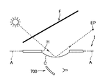
- a display device 700 for a vehicle described in Patent Document 1 is attached in an instrument panel I having an opening H provided in a wall A facing the windshield F, and the opening H Through which the image is projected onto the windshield F.
- a transparent cover C that closes the opening H in order to prevent dust or moisture from entering the opening H may be provided. The light may be reflected by the cover C and head toward the passenger's eye point EP, which may cause discomfort.
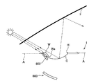
- a vehicle display device 800 shown in FIGS. 5 and 14 is conceivable as a configuration for avoiding that external light travels toward the passenger's eye point EP.
- the vehicle display device 800 is provided in the instrument panel I.
- the instrument panel I has an opening H formed in a wall A facing the windshield F, and a front bezel portion W provided on the front side of the opening H has a front side to a rear side (FIGS. 5 and 14). , A light-transmitting falling wall portion Wa that gradually goes downward as it goes from left to right).
- the opening H is provided with a cover C that gradually moves upward as it goes from the front side to the rear side of the vehicle.
- the vehicle display device 800 projects an image on the windshield F through the opening H.
- the light guide member 802 cannot sufficiently guide light to the vicinity of the descending wall portion Wa, or when the guided light is emitted from the light guide member 802, the descending wall is efficiently provided.
- the falling wall portion Wa may appear darker than the peripheral portion, or may not face the portion Wa.
- the first object of the present invention is to provide a bezel body and a vehicle display device that can effectively suppress discomfort given to the passenger by making the reflection on the windshield less noticeable.
- the end surface (light entrance surface 802a) on the vehicle front side of the light guide member 802 is an instrument. Since it is disposed so as to be exposed from the panel I, dust or the like may enter through a gap between the light guide member 802 and the descending wall portion W, and the light guide function is achieved because dust adheres to the light guide member 802. The amount of light guided to the descending wall W by the light guide member 802 may decrease. Further, for example, external light such as sunlight is incident on the light incident surface 802a of the light guide member 802 from above, so that light incident on the light incident surface 802a enters the lower surface 802b of the light guide member 802.
- the incident angle i becomes small, and there is a possibility that a part of the light is emitted outside the light guide member 802 without being totally reflected on the lower surface 802b.
- the amount of light guided may be reduced.
- induced to the falling wall part W falls, the falling wall part W cannot be brightened so that a light-dark difference may become small, and reflection on the windshield F may not be conspicuous enough. It may not be possible.
- a second object of the present invention is to provide a bezel body that can effectively make the reflection on the windshield inconspicuous, and a vehicle display device including the bezel body.
- the invention described in claim 1 is an image projector that is fitted into a wall facing a windshield in an instrument panel of a vehicle and disposed in the instrument panel.
- a bezel body comprising a bezel member that forms part or all of the periphery of an opening for projecting an image on the windshield, comprising a plate-shaped light guide member, the bezel member being located with respect to the opening
- a front bezel portion disposed on the front side of the vehicle, and the front bezel portion is lifted from the opposite wall so that a front end portion of the vehicle has a gap between the front wall and the opposite wall.
- a light-transmitting descending wall portion that gradually goes downward and reaches the opening as it goes from the front side to the rear side of the vehicle.
- Light that is disposed below the sel part and that enters the front end surface of the vehicle is guided to the descending wall portion, and is changed to a predetermined range on the lower surface on the rear side of the vehicle by changing the path in the plate thickness direction.
- the bezel body is characterized in that a reflecting portion for reflecting the light is formed.
- a diffusion portion that diffuses light emitted upward is formed on the upper surface of the light guide member. is there.
- the invention described in claim 3 is the bezel body according to claim 1 or 2, further comprising a support member that supports the light guide member from below and reflects light from above. It is.
- an image projector disposed in an instrument panel of a vehicle is fitted into a facing wall of a windshield in the instrument panel, and the image projector is imaged on the windshield.
- a vehicle display device comprising: a bezel body having a bezel member that forms a part or all of a peripheral edge of an opening for projecting an object, wherein the bezel body is any one of claims 1 to 3. It is comprised with the bezel body of description, It is a display apparatus for vehicles characterized by the above-mentioned.
- an opening for projecting an image onto the windshield by an image projector that is fitted into a wall facing the windshield of the instrument panel of the vehicle and disposed in the instrument panel.
- a bezel body having a bezel member that forms part or all of the peripheral edge of the vehicle, wherein the bezel member has a front bezel portion disposed on the front side of the vehicle with respect to the opening, and the front bezel portion
- the front end of the vehicle is arranged so as to be lifted from the facing wall so that a gap is formed between the vehicle and the facing wall, and gradually moves downward from the front side to the rear side of the vehicle.
- a light-transmitting descending wall portion that reaches the opening, and the bezel body is formed in a plate shape, and is disposed to overlap the inner surface of the front bezel portion.
- a light window member provided between the light guide member and the light guide member is housed in the housing space with an end face on the front side of the vehicle facing the light window member, and the light window member is
- the bezel body includes a light deflecting portion that deflects light taken from the gap so as to be directed toward an end surface of the light guide member on a front side of the vehicle.
- the invention described in claim 6 is the invention described in claim 5, wherein the daylighting window member has a plate-like window main body portion, and the light deflection portion is an inner surface or an outer surface of the window main body portion. And a plurality of wedge-shaped ridges or grooves extending in the width direction of the vehicle.
- an image projector disposed in an instrument panel of a vehicle is fitted into a facing wall of a windshield in the instrument panel, and the image projector has an image on the windshield.
- the front end portion of the front bezel portion is disposed so as to be lifted so as to leave a gap with the opposing wall, and the light guide member is disposed below the front bezel portion. Since it is provided, outside light irradiated into the vehicle from the front side through the windshield is taken in from the front end surface of the light guide member, and the outside light is guided toward the descending wall portion by the light guide member. Can do. Furthermore, since the reflecting portion is formed in a predetermined range on the rear side of the vehicle on the lower surface of the light guide member, it is easy to reflect upward by changing the path of the guided outside light in the plate thickness direction. The light can be efficiently irradiated from the light guide member toward the descending wall portion. Therefore, the reflection of the descending wall portion on the windshield can be made inconspicuous, and the discomfort given to the passenger can be effectively suppressed.
- the diffusion portion that diffuses light is formed on the upper surface of the light guide member, the light emitted from the upper surface of the light guide member is concentrated at a specific location. It is possible to prevent occurrence of unevenness in the reflection of the descending wall portion on the windshield.
- the support member that supports the light guide member from below reflects light from above, the light emitted downward from the light guide member is reflected and guided again.
- the light returned to the optical member and the light taken into the light guide member can be used effectively. Therefore, it is not necessary to enlarge the front bezel portion in the vertical direction or provide another member in order to increase the amount of light collected.
- the reflection part formed on the light guide member makes the reflection on the windshield of the descending wall part less noticeable as described above, and the discomfort given to the passenger is effective. Can be suppressed.
- the accommodation space of the light guide member opened toward the gap between the opposing wall of the instrument panel and the front bezel portion of the bezel member is defined as the front bezel portion. It is formed between the case part.
- a daylighting window member is provided between the front bezel portion and the case member so as to seal the opening of the housing space and to take light from the gap into the housing space.
- the light guide member is housed in the housing space with the end face on the front side of the vehicle facing the daylighting window member, and the daylighting window member heads the light taken from the gap toward the end face of the light guide member on the front side of the vehicle. In this way, an optical deflecting unit for deflecting is provided.
- the opening of the accommodation space in which the light guide member is accommodated by the daylighting window member is sealed, it is possible to suppress the intrusion of dust into the accommodation space. Since the light taken in from the gap by the light deflector is deflected so as to go to the end face of the light guide member on the front side of the vehicle, the light going to the end face is in a direction orthogonal to or near to the end face. Therefore, the amount of light reaching the end portion on the rear side of the vehicle in the light guide member can be secured. As a result, a decrease in the amount of light guided to the descending wall can be suppressed, the descending wall can be brightened so as to reduce the difference in brightness, and the reflection on the windshield is effectively inconspicuous. Can do.
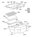
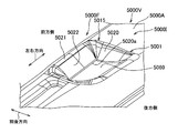
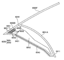
- FIG. 1 is a perspective view showing a vehicle display device according to a first embodiment of the first invention.
- FIG. It is II-II sectional drawing of the said display apparatus for vehicles. It is sectional drawing which expands and shows the principal part of the said display apparatus for vehicles. It is sectional drawing which shows the display apparatus for vehicles of a prior art. It is sectional drawing which shows the display apparatus for vehicles of another prior art. It is a perspective view which shows a mode that the display apparatus for vehicles concerning 2nd Embodiment of 1st invention was assembled
- FIG. 17 is a cross-sectional view taken along the line 2000II-2000II of the vehicle display device of FIG. It is a disassembled perspective view of the display apparatus for vehicles of FIG. (A) is an enlarged sectional view for explaining the progress of light in the light guide member of the vehicle display device of FIG. 16, and (B) is a sectional view taken along the line 2000I-2000I in (A).
- FIG. 17 is a rear perspective view of the light guide member shown in FIG. 16. It is sectional drawing which shows the display apparatus for vehicles of the prior art of 2nd invention. It is sectional drawing which shows the display apparatus for vehicles of the other prior art of 2nd invention.
- FIG. 3 is a cross-sectional view of the vehicle display device taken along line 3000II-3000II. It is an expanded sectional view which expands and shows the principal part of the said display apparatus for vehicles. It is sectional drawing which shows the display apparatus for vehicles of the prior art of 3rd invention. It is sectional drawing which shows the display apparatus for vehicles of the other prior art of 3rd invention. It is a perspective view which shows a mode that the display apparatus for vehicles concerning one Embodiment of 4th invention was assembled
- FIG. 32 is a cross-sectional view of the vehicle display device of FIG. 30 taken along the line 4000II-4000II. It is a disassembled perspective view of the display apparatus for vehicles of FIG.
- FIG. 33A is an enlarged partial cross-sectional view of the vehicle display device of FIG. 32 with the shutter opened
- FIG. 33B is an enlarged partial cross-sectional view of the vehicle display device of FIG. 32 with the shutter closed.
- FIG. 38 is an enlarged cross-sectional view illustrating the progress of light in the vehicle display device of FIG. 37.
- FIG. 38 is an enlarged cross-sectional view illustrating the progress of light in a modification of the vehicle display device of FIG.
- FIG. 38 is an enlarged cross-sectional view for explaining the progress of light in another modification of the vehicle display device of FIG. 37.
- FIG. 2 is a cross-sectional view of the vehicle display device, 6000II-6000II.
- FIG. It is sectional drawing which expands and shows the principal part of the said display apparatus for vehicles.
- the vehicular display device 1 has an opposing wall A between the image projector 2 disposed in the instrument panel I of the vehicle and the windshield F in the instrument panel I.
- An apparatus for projecting the traveling state of the vehicle such as speed and road conditions on the windshield F as an image, for example, with the cover 3 provided in the opening H formed in the cover 3 and the bezel body 4 provided around the cover 3. is there.
- the vehicle front-rear direction, the left-right direction, the front side and the rear side, and the upper side and the lower side in the front-rear direction are as shown in FIGS.
- the image projector 2 includes a projector main body 21 and a mirror 22, and projects an image toward the windshield F through the opening H. At this time, the image projector 2 causes the image to form an image far away from the passenger so that the image can be recognized naturally even when the passenger is focused far away during driving.
- the cover 3 is made of, for example, a transparent resin or glass, and transmits light emitted from the image projector 2 and protects the image projector 2 from dust and moisture. Further, the cover 3 is provided at a position where the front side end 3a is lower than the rear side end 3b (that is, provided at the front lower side), and external light is reflected to reach the eye point EP of the passenger. Is suppressed.
- the bezel body 4 includes a bezel member 41 that forms the periphery of the opening H, a light guide member 42 provided below a front bezel portion 41A described later, and a support member 43 that supports the light guide member 42 from below. .
- the bezel member 41 is made of, for example, a resin having substantially the same color as the facing wall A, and includes a front bezel portion 41A on the front side, a rear bezel portion 41B on the rear side, and a front bezel portion 41A and a rear bezel portion at both ends in the left-right direction.
- the left and right bezel portions 41 ⁇ / b> C provided between the first wall 41 ⁇ / b> B and the opposite wall A are supported, and the cover 3 is supported.
- Each bezel part 41A, 41B, 41C may be formed separately, respectively, and may be formed integrally.
- the front bezel portion 41A is arranged so as to be lifted from the opposing wall A so that a gap between the front bezel portion and the opposing wall A is opened, and gradually opens downward from the front side toward the rear side. It has a descending wall portion 411 that reaches H. That is, the front bezel portion 41 ⁇ / b> A is configured to support the front side end portion 3 a of the cover 3 at the lower end (rear end) of the descending wall portion 411.
- the descending wall portion 411 has light transparency and the upper surface has substantially the same color as the opposing wall A, and transmits light from below upward.
- the transmitted light is transmitted to the upper surface of the opposing wall A and the bezel member 41. It is comprised so that it may become substantially the same color as reflected light.
- the entire front bezel portion 41A may be the descending wall portion 411, or only the portion of the front bezel portion 41A that is difficult to receive external light may be the descending wall portion 411 and the other portions may be configured to be opaque.
- the light guide member 42 is made of a transparent and high refractive index member such as glass or resin, and extends in the front-rear direction between the front bezel portion 41A and the support member 43 as shown in an enlarged view in FIG. It is formed in a plate shape, and is configured such that light incident rearward from the front end surface 421 is totally reflected on the inner side and travels backward. Further, the light guide member 42 is formed so that the plate thickness dimension becomes smaller from the front side toward the rear side.
- a reflection part 422 having a wedge shape in cross section formed by a convex part extending in the left-right direction is formed. Reflection is performed by changing in the plate thickness direction (that is, upward).
- the reflection part 422 should just be formed in the suitable range of the back side at least according to the refractive index, shape, etc. of the light guide member 42, and may be formed in the whole lower surface.
- a fine concavo-convex diffusing portion 423 is formed in a range of the upper surface of the light guide member 42 facing the reflecting portion 422 so that light emitted upward from the light guide member 42 is diffused. Yes. Note that the diffusion portion 423 may be formed on the entire top surface of the light guide member 42.
- the support member 43 is supported by the bezel member 41 while supporting the light guide member 42, and a reflection member 431 is provided on the upper surface so as to reflect light from above. Further, the support member 43 has an end on the front side that is provided at substantially the same height as the upper surface of the opposing wall A, forms a daylighting portion 44 between the front bezel portion 41A on the front side, and windshield F The external light irradiated from the front side through the light can be taken in from the front end surface 421 of the light guide member 42 through the daylighting portion 44.
- the daylighting unit 44 may be provided with a window that transmits light.
- the light emitted from the upper surface is diffused by the diffusing portion 423 toward the upper front bezel portion 41A, and the light emitted from the lower surface is reflected upward by the reflecting member 431 of the support member 43 and is incident on the light guide member 42 again. To do.
- the light traveling in the light guide member 42 toward the rear side reaches the reflecting portion 422 on the lower surface, the light is reflected toward the plate thickness direction, reaches the upper surface, and is emitted while being diffused by the diffusing portion 423. It reflects and proceeds backwards.
- outside light is guided from the front side toward the rear side by the light guide member 42 and is emitted toward the upper front bezel portion 41A.
- the light that has reached the descending wall portion 411 in the front bezel portion 41 ⁇ / b> A passes through the descending wall portion 411 toward the windshield, and is reflected in the descending wall portion 411.
- the reflecting portion 422 is formed in a predetermined range on the rear side of the lower surface of the light guide member 42, the light guided outside light is easily reflected upward, and the falling wall portion from the light guide member 42. Light can be efficiently irradiated toward the region 411. Therefore, it is possible to prevent the descending wall portion 411 from being reflected darkly on the windshield F, and to effectively suppress discomfort given to the passenger by making the reflection inconspicuous.
- the diffusion portion 423 is formed on the upper surface of the light guide member 42, the light emitted from the upper surface of the light guide member 42 is prevented from concentrating on a specific location, and the windshield F of the descending wall portion 411 is protected. It is possible to suppress unevenness in the reflection on the screen.
- the support member 43 includes the reflection member 431, the light taken into the light guide member 42 can be used effectively. Therefore, in order to increase the amount of light collected to the light guide member 42, it is not necessary to enlarge the light collecting portion 44 or the front end surface 421 of the light guide member 42 in the vertical direction.
- the plate thickness dimension of the light guide member 42 decreases from the front side toward the rear side, the light traveling in the light guide member 42 is concentrated in the plate thickness direction (that is, the vertical direction), and the descending wall The light can be easily guided toward the lower end portion of the portion 411, and the reflection of the descending wall portion 411 on the windshield F can be made inconspicuous.
- the present invention is not limited to the above-described embodiment, and includes other configurations and the like that can achieve the object of the present invention, and the following modifications and the like are also included in the present invention.
- the diffusion portion 423 is formed in the range of the upper surface of the light guide member 42 facing the reflection portion 422.
- the diffusion portion is formed on the entire upper surface of the light guide member.
- it may be omitted from the light guide member.
- a diffusion portion may be formed on the lower surface of the descending wall portion.
- the bezel body 4 includes the support member 43 and the support member 43 is provided with the reflection member 431.
- the reflection member is omitted and mirror processing is performed on the upper surface of the support member. It may be configured to reflect light from above. If the lower surface of the light guide member is configured to sufficiently reflect light, the support member may be configured not to reflect light, and the bezel member may be configured to support the light guide member. If it is, the support member may be omitted.
- the thickness of the light guide member 42 is reduced from the front side toward the rear side.
- the light guide member has an appropriate plate thickness and shape and extends in the front-rear direction. Anything is acceptable.
- a bezel body and a vehicle display device according to a second embodiment of the present invention will be described with reference to FIGS.
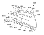
- FIG. 6 is a perspective view showing a state in which the vehicle display device according to the present embodiment is assembled to the instrument panel.
- FIG. 7 is a view of the vehicle display device of FIG. 6 as viewed from the front side of the vehicle.
- FIG. 8 is a cross-sectional view of the vehicle display device of FIG.
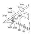
- FIG. 9 is an exploded perspective view of the vehicle display device of FIG.
- FIG. 10 is a view for explaining a daylighting window member provided in the vehicle display device of FIG. 6.
- FIG. 11 is an enlarged cross-sectional view for explaining the progress of light in the light guide member of the vehicle display device of FIG. 6 and shows a case where the sun is at a relatively low position.
- FIG. 11 is an enlarged cross-sectional view for explaining the progress of light in the light guide member of the vehicle display device of FIG. 6 and shows a case where the sun is at a relatively low position.
- FIG. 12 is an enlarged cross-sectional view for explaining the progress of light in the light guide member of the vehicle display device of FIG. 6 and shows a case where the sun is at a relatively high position.
- “front / rear / up / down / left / right” corresponds to front / rear, up / down / left / right of the vehicle V.
- the vehicular display device 1 is attached to an instrument panel 1000I of a vehicle 1000V and is used as a head-up display device that projects an image onto a windshield 1000F. Is.
- the vehicle display device 1001 includes an image projector 1010 and a bezel body 1015 as shown in FIGS.
- the image projector 1010 includes a display source 1011 for projecting an image, a reflection unit 1012 that reflects an image from the display source 1011, a synthetic resin casing 1013 that houses the display source 1011 and the reflection unit 1012, and have.
- the housing 1013 includes an upper wall portion 1013a, a lower wall portion 1013b disposed to face the upper wall portion 1013a, and a peripheral wall portion 1013c connected to the peripheral edges of the upper wall portion 1013a and the lower wall portion 1013b.
- the upper wall portion 1013a is provided with an opening 1013d that is disposed so as to overlap with an opening 1020a of a bezel member 1020 described later.
- the image projector 1010 reflects the image projected by the display source 1011 on the reflection unit 1012, and projects the image onto the windshield 1000F through the opening 1013d. Thereby, it is visually recognized as an image displayed on the windshield 1000F by the passenger of the vehicle 1000V.
- the bezel body 1015 includes a bezel member 1020, a light guide member 1030, a support member 1040 as a case member, a daylighting window member 1050, and a cover 1060.
- the bezel member 1020 is made of, for example, a semi-transparent (light transmissive) synthetic resin, and has an annular shape in plan view having an opening 1020a at the center, and has a shape that gradually goes downward from the outer peripheral edge toward the inner peripheral edge. is doing.
- the bezel member 1020 is formed in a shape that is an upside down version of a hollow, substantially square frustum with an upper end surface and a lower end surface.
- the bezel member 1020 is placed in a hole provided in a wall 1000A facing the windshield 1000F of the instrument panel 1000I. That is, the bezel member 1020 is fitted into the opposing wall 1000A and forms the entire periphery of the opening 1020a for the image projector 1010 disposed in the instrument panel 1000I to project an image on the windshield 1000F. .
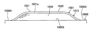
- the bezel member 1020 has a front bezel portion 1021 disposed on the front side of the vehicle 1000V when fitted into the opposing wall 1000A.
- the front bezel portion 1021 is disposed so as to float upward from the opposing wall 1000A so that the front end 1021a of the vehicle 1000V has a gap 1000S between the front bezel portion 1021 and the opposing wall 1000A (that is, with respect to the opposing wall 1000A). Placed above).
- the front bezel portion 1021 has a descending wall portion 1022 that gradually goes downward and reaches the opening 1020a as it goes from the front side to the rear side of the vehicle 1000V.
- the bezel member 1020 When the bezel member 1020 is fitted into the opposing wall 1000A, a part of the front side of the outer peripheral edge of the bezel member 1020 (that is, the front end 1021a of the front bezel portion 1021 of the vehicle 1000V) is lifted above the opposing wall 1000A. (FIG. 7), and other portions of the outer peripheral edge other than the portion are arranged so that the outer surface (upper surface) of the bezel member 1020 and the outer surface of the opposing wall A are smoothly connected (FIG. 6). At this time, the opening 1020a of the bezel member 1020 and the opening 1013d of the image projector 1010 are arranged so as to overlap in the vertical direction. Further, the bezel member 1020 is adjusted to have the same appearance as that of the opposing wall 1000A, for example, so that the difference in reflection on the windshield 1000F from the opposing wall 1000A of the instrument panel 1000I is not noticeable. And surface processing.
- the light guide member 1030 is formed in a substantially rectangular plate shape (FIG. 9) in a plan view using a highly transparent material such as synthetic resin such as glass, acrylic, and polycarbonate, and is formed on the inner surface of the front bezel portion 1021. They are placed one above the other with a slight gap (ie, they are placed along the inner surface of the front bezel portion 1021).
- the light guide member 1030 is formed thick on the front side and thin on the rear side, and the portion between the thickly formed portion and the thinly formed portion is from the front to the rear. It is formed so as to become thinner gradually as it goes to.
- the surface of the light guide member 1030 facing downward is formed in a flat shape, and the surface of the downward wall portion 1022 facing upward is a slope that gradually descends from the front toward the rear in the middle portion in the front-rear direction. A surface is formed.
- the light guide member 1030 is formed so as to guide the light that has entered the light incident surface 1030a, which is the front end surface of the vehicle 1000V, to the rear end portion and to emit light from the surface on the descending wall portion 1022 side.
- the light guide member 1030 guides light in the light guide direction from the front end portion with the light incident surface 1030a toward the opposite rear end portion. Thereby, light can be guided toward the light-transmitting descending wall portion 1022 to illuminate the vicinity of the opening 1020a in the descending wall portion 1022.
- the support member 1040 has a mounting portion 1041 made of synthetic resin and a pair of leg portions 1042.
- the placement portion 1041 is a portion on which the light guide member 1030 is placed, and is formed in a substantially plate shape whose plan view shape is slightly larger than the plan view shape of the light guide member 1030.
- the mounting portion 1041 is disposed at a distance from the inner surface of the front bezel portion 1021, and the front end portion 1041a of the vehicle 1000V is aligned with the end portion 1021a of the front bezel portion 1021 in a generally vertical direction.
- both end portions facing in the left-right direction are disposed in contact with the inner surface of the bezel member 1020.
- the mounting portion 1041 forms an accommodation space 1000 ⁇ / b> K that accommodates the light guide member 1030 between the placement portion 1041 and the front bezel portion 1021.
- the accommodation space 1000K opens toward the gap 1000S.
- the light guide member 1030 is disposed such that the light incident surface 1030a faces the gap 1000S through the opening of the accommodation space 1000K.
- the pair of leg portions 1042 are portions that connect the mounting portion 1041 and the housing 1013 of the image projector 1010, and respectively forward and upward from both left and right ends of the front surface of the peripheral wall portion 1013 c of the housing 1013. It is extended (FIG. 9).
- the base end of the leg portion 1042 is integrally fixed to the housing 1013, and a fixing portion 1041b provided on the lower surface of the placement portion 1041 is fixed to the distal end.
- the lighting window member 1050 is formed by using a highly transparent material such as synthetic resin such as glass, acrylic, and polycarbonate.
- the daylighting window member 1050 is provided so as to seal the opening of the accommodation space 1000K and to take light from the gap 1000S into the accommodation space 1000K.
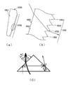
- the daylighting window member 1050 includes a window main body portion 1051 and a light refraction portion 1052 as a light deflection portion.
- the window main body 1051 is formed in a substantially trapezoidal plate shape (FIGS. 7 and 9) whose plan view is the same as the opening of the accommodation space 1000K.
- the window main body portion 1051 is formed by sealing the front end 1021a of the front bezel portion 1021 and the mounting portion 1041 of the support member 1040 so as to seal (seal) the opening of the accommodation space 1000K in which the light guide member 1030 is accommodated. It arrange
- An outer surface 1051a (surface facing the vehicle front side) of the window main body 1051 is formed in a flat shape, and a light refracting portion 1052 for deflecting light by refraction is provided on the inner surface 1051b (surface facing the vehicle rear side). ing.
- the light refracting portion 1052 is provided on the inner surface 1051b of the window main body portion 1051, and has a plurality of ridges 1053 having a wedge-shaped cross section (prism shape) extending over the entire inner surface 1051b of the window main body portion 1051 in the left-right direction. Yes.
- the plurality of ridges 1053 are arranged in the vertical direction to form a prism pattern.
- the light refracting unit 1052 refracts the light incident on the outer surface 1051a of the window main body 1051 toward the light incident surface 1030a of the light guide member 1030, that is, with respect to the light incident surface 1030a of the light guide member 1030.
- the shape of the ridge 1053 is set so as to be refracted in a direction perpendicular to or perpendicular to the perpendicular direction.
- the light refracting portion 1052 has a plurality of protrusions 1053 having a wedge shape in cross section provided on the inner surface of the window main body portion 1051, but is not limited to this, and the light refracting portion 1052. However, it may be provided on the outer surface 1051a of the window main body 1051 and may be provided with a concave groove having a wedge-shaped cross section instead of a part or all of the ridges 1053.
- all the shapes of the plurality of ridges 1053 may be the same, or a plurality of different shapes (that is, different light refraction directions) ridges 1053 may be provided in a mixed manner.
- the light refracting unit 1052 deflects light by refraction.
- the present invention is not limited to this, and a light diffracting unit that deflects light by diffraction may be provided in place of the light refracting unit 1052.
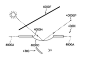
- FIG. 10C schematically shows an example of a path along which light that has entered the prism-shaped translucent member travels. It is considered that the light travels on the same path in the projection 1053 of the daylighting window member 1050.
- the cover 1060 is formed on a thin plate using a highly transparent material such as synthetic resin such as glass, acrylic, or polycarbonate, and is fixed to the periphery of the opening 1020a so as to close the opening 1020a of the bezel member 1020. Attached.
- the cover 1060 is disposed so as to go upward as it goes from the front side to the rear side of the vehicle 1000V (FIG. 8). Thereby, it can suppress that the light which hit the cover 1060 goes directly to a passenger
- the incident angle of the light with respect to the lower surface 1030b is relatively large, the light is totally reflected on the lower surface 1030b and travels toward the rear end of the light guide member 1030. Thereby, the amount of light emitted at the rear side end of the light guide member 1030 can be secured.
- the accommodation space 1000K of the light guide member 1030 opened toward the gap 1000S between the facing wall 1000A of the instrument panel 1000I and the front bezel portion 1021 of the bezel member 1020 It is formed between the bezel portion 1021 and the mounting portion 1041 of the support member 1040.
- a daylighting window member 1050 is provided between the front bezel portion 1021 and the mounting portion 1041 so as to seal the opening of the accommodation space 1000K and to take light from the gap 1000S into the accommodation space 1000K.
- the light guide member 1030 is accommodated in the accommodation space 1000K with the light incident surface 1030a facing the daylighting window member 1050, and the light that the daylighting window member 1050 has taken in from the gap 1000S is the light incident surface 1030a of the light guide member 1030.
- a light refracting portion 1052 that refracts the light toward the head. Since it did in this way, since the opening of the accommodation space 1000K in which the light guide member 1030 is accommodated is sealed by the daylighting window member 1050, the entrance of dust into the accommodation space 1000K can be suppressed.
- the light taken from the gap 1000S is refracted by the light refracting portion 1052 of the daylighting window member 1050 so as to be directed toward the light incident surface 1030a of the light guide member 1030. Therefore, the light toward the light incident surface 1030a is incident on the light incident surface 1030a.
- the light travels in a direction orthogonal to or close to the orthogonal direction, so that the amount of light reaching the rear end of the vehicle 1000V in the light guide member 1030 can be secured. Thereby, the fall of the quantity of the light guide
- the daylighting window member 1050 has a plate-like window main body portion 1051, and the light refracting portion 1052 has a plurality of cross-sectional wedge shapes extending in the width direction of the vehicle 1000 V provided on the inner surface 1051 b of the window main body portion 1051.
- the ridge 1053 is provided. Since it did in this way, while being able to comprise the light refracting part 1052 by a simple shape, the refractive direction of light can be easily adjusted by changing the cross-sectional shape of the protruding item
- the present invention has been described with reference to a preferred embodiment, but the bezel body and the vehicle display device of the present invention are not limited to the configuration of the above embodiment.
- the bezel member 1020 is formed in an annular shape in plan view and has the front bezel portion 1021, but is not limited thereto.
- the bezel member 1020 is configured by only the front bezel portion 1021, only the periphery of the opening 1020a on the front side of the vehicle 1000V is formed, and the remaining periphery of the opening 1020a is formed by the opposing wall of the instrument panel 1000I. Also good.
- the entire bezel member 1020 is formed of a light-transmitting synthetic resin.
- the configuration is not limited thereto, and at least the descending wall portion 1022 is light-transmitting. Good.
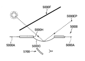
- a vehicle display device as a head-up display device that projects an image onto a windshield of a vehicle is provided in an instrument panel (see, for example, Japanese Patent Application Laid-Open No. 2007-148092).
- the vehicle display device 2700 described in this patent document is mounted in an instrument panel 2000I having an opening 2000H provided on a wall 2000A facing the windshield 2000F, and the front display through the opening 2000H.
- An image is projected onto the glass 2000F.
- a transparent cover 2000C that closes the opening 2000H may be provided in order to prevent dust or moisture from entering the opening H.
- the light may be reflected by the cover 2000C and head toward the passenger's eye point 2000EP, which may cause discomfort.
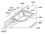
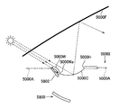
- a vehicle display device 2800 shown in FIG. 23 is conceivable as a configuration for avoiding that external light travels toward the passenger's eye point 2000EP.
- the vehicle display device 2800 is provided in the instrument panel 2000I.
- the instrument panel 2000I has an opening 2000H formed on a wall 2000A facing the windshield 2000F, and a front bezel portion 2000W provided on the front side of the opening 2000H extends from the front side to the rear side (left side in FIG. 23).
- a light-transmitting descending wall portion 2000Wa that gradually goes downward as it goes from side to side) is formed.
- the opening 2000H is provided with a cover 2000C that gradually moves upward as it goes from the front side to the rear side of the vehicle.
- the vehicle display device 2800 projects an image onto the windshield 2000F through the opening 2000H.
- the descending wall portion 2000Wa is provided and the vehicle front side of the cover 2000C is located below the rear side, it is possible to make it difficult for outside light to reach the cover 2000C, and for the cover 2000C. It can suppress that the reflected external light goes to a passenger's eyepoint 2000EP.
- the distance between the upper surface of the light guide member 2802 and the lower surface of the descending wall portion 2000Wa is uniform. Not. For this reason, the light incident on the descending wall portion 2000Wa from the light guide member 2802 is also not uniform, and there is a problem that color unevenness occurs in the descending wall portion 2000Wa.
- An object of the present invention is to provide a bezel body and a vehicle display device which can effectively suppress discomfort given to a passenger by making the reflection on the windshield less noticeable.
- the invention ⁇ 1 ⁇ of the present invention is fitted into an instrument panel of a vehicle, and an image projector disposed in the instrument panel projects an image on a windshield.
- a bezel member that forms part or all of the periphery of the opening for the plate, and a plate-like light guide member that is disposed below the front bezel portion of the bezel member that is disposed on the front side of the vehicle with respect to the opening.
- the front bezel portion is disposed above the instrument panel so that a front end of the vehicle has a gap between the instrument panel and the rear side of the vehicle.
- a light-transmitting descending wall portion provided so as to gradually go downward and reach the opening as it goes to the light guide member, and the light guide member enters from the gap
- a bezel body characterized in that the upper surface has a shape along the lower surface of the descending wall.
- a reflecting portion that reflects light by changing a course in a plate thickness direction of the light guide member is formed in a predetermined range on the rear side of the vehicle on the lower surface of the light guide member. It is a bezel body as described in the invention ⁇ 1 ⁇ .
- the invention ⁇ 3 ⁇ is the bezel body according to the invention ⁇ 1 ⁇ or ⁇ 2 ⁇ , comprising a brightness enhancement film disposed on the upper surface of the light guide member and formed by arranging a plurality of prisms. .
- the invention ⁇ 4 ⁇ includes a brightness enhancement film that is arranged on the upper surface of the light guide member and is formed by arranging a plurality of prisms extending along the front-rear direction of the vehicle, and the vehicle on the lower surface of the light guide member
- the bezel body according to the invention ⁇ 1 ⁇ characterized in that a reflecting portion in which a plurality of prisms extending in the left-right direction of the vehicle are arranged in a predetermined range on the rear side of the vehicle.
- the invention ⁇ 5 ⁇ includes an image projector disposed in an instrument panel of a vehicle, and a part of a periphery of an opening that is fitted in the instrument panel and the image projector projects an image on a windshield or
- a display device for a vehicle comprising a bezel body having a bezel member forming the whole, wherein the bezel body is constituted by the bezel body according to any one of the inventions ⁇ 1 ⁇ to ⁇ 4 ⁇ . It is the display apparatus for vehicles characterized by these.
- the front end portion of the front bezel portion is disposed above the instrument panel so that a gap is formed between the front bezel portion and the light guide member. Since it is provided below the front bezel portion, the light guide member can guide the light incident from the gap through the windshield to illuminate the descending wall portion. Furthermore, since the upper surface of the light guide member is shaped along the lower surface of the descending wall portion, the distance between the upper surface of the light guide member and the lower surface of the descending wall portion is uniform, and color unevenness of the descending wall portion can be suppressed. . Therefore, the reflection of the descending wall portion on the windshield can be made inconspicuous, and the discomfort given to the passenger can be effectively suppressed.
- the reflecting portion is formed in the predetermined range on the lower surface of the light guide member on the rear side of the vehicle so as to change the course in the plate thickness direction of the light guide member and reflect the light. Therefore, the external light can be easily reflected toward the descending wall portion, and light can be efficiently irradiated from the light guide member toward the descending wall portion. Therefore, the reflection of the descending wall portion on the windshield can be made more inconspicuous, and the discomfort given to the passenger can be effectively suppressed.
- the brightness enhancement film formed by arranging a plurality of prisms is arranged on the upper surface of the light guide member, light is more efficiently emitted from the light guide member toward the descending wall portion. Can be irradiated.
- a brightness enhancement film formed by arranging a plurality of prisms extending along the front-rear direction of the vehicle is disposed on the upper surface of the light guide member.
- FIG. 16 is a perspective view illustrating a state in which the vehicle display device according to the embodiment of the present invention is assembled to the instrument panel.
- FIG. 17 is a view of the vehicle display device of FIG. 16 as viewed from the front side of the vehicle.
- 18 is a cross-sectional view of the vehicle display device of FIG. 16 taken along the line 2000II-2000II.
- FIG. 19 is an exploded perspective view of the vehicle display device of FIG. 20A is an enlarged cross-sectional view for explaining the progress of light in the light guide member of the vehicle display device shown in FIG. 16, and
- FIG. 20B is a cross-sectional view taken along the line 2000I-2000I in FIG.
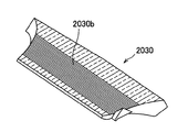
- FIG. 22 is a rear perspective view of the light guide member shown in FIG. 16.
- the vehicle display device 2001 of this embodiment is attached to an instrument panel 2000I of a vehicle 2000V and is used as a head-up display device that projects an image onto a windshield 2000F. Is.
- the front-rear direction, the left-right direction, the front side and the rear side in the front-rear direction, and the upper and lower sides of the vehicle 2000V in the present embodiment are as shown in FIGS.
- the vehicle display device 2001 includes an image projector 2010 disposed in the instrument panel 2000I of the vehicle 2000V, and a bezel body 2015 disposed in the instrument panel 2000I. I have.
- the image projector 2010 includes a display source 2011 for projecting an image, a reflection unit 2012 that reflects an image from the display source 2011, and a synthetic resin that houses the display source 2011 and the reflection unit 2012. And a housing 2013 made of steel.
- the housing 2013 includes an upper wall portion 2013a, a lower wall portion 2013b disposed to face the upper wall portion 2013a, and a peripheral wall portion 2013c connected to the peripheral edges of the upper wall portion 2013a and the lower wall portion 2013b.
- the upper wall portion 2013a is provided with an opening 2013d that is disposed so as to overlap an opening 2020a of a bezel member 2020 described later.
- the image projector 2010 reflects the image projected by the display source 2011 by the reflection unit 2012 and projects the image onto the windshield 2000F through the opening 2013d. Thereby, the passenger of the vehicle 2000V can be visually recognized as an image displayed on the windshield 2000F.
- the bezel body 2015 includes a bezel member 2020, a light guide member 2030, a brightness enhancement film 2040, a support member 2050 as a case member, and a cover 2060. .
- the bezel member 2020 is made of, for example, a semi-transparent (light transmissive) synthetic resin and has an annular shape in plan view having an opening 2020a at the center.
- the bezel member 2020 is provided so as to be gradually lowered as it goes from the outer peripheral edge to the inner peripheral edge, and to be inclined so that its inclination increases as it approaches the inner peripheral edge.
- the bezel member 2020 is fitted into a hole provided in the instrument panel 2000I, and the image projector 2010 arranged in the instrument panel 2000I covers the entire periphery of the opening 2020a for projecting an image onto the windshield 2000F. Forming.
- the front bezel portion 2021 disposed on the front side of the vehicle 2000V with respect to the opening 2020a in the bezel member 2020 includes the instrument 20001 so that a gap 2000S is formed between the front end 2021a of the vehicle 2000V and the instrument panel 2000I. Arranged above panel 2000I. Further, the front bezel portion 2021 has a descending wall portion 2022 that is curved so that the slope gradually increases downward toward the opening 2020a as it goes from the front side to the rear side of the vehicle 2000V, and the inclination increases as it approaches the opening 2020a. Have.
- a portion of the front side of the outer peripheral edge of the bezel member 2020 (that is, the front side end portion 2021a of the vehicle 2000V of the front bezel portion 2021) is more than the instrument panel 2000I. It arrange
- the opening 2020a of the bezel member 2020 and the opening 2013d of the image projector 2010 are arranged so as to overlap in the vertical direction.
- the bezel member 2020 is subjected to, for example, the adjustment of color and surface processing similar to the instrument panel 2000I in order to prevent the difference in the reflection of the instrument panel 2000I on the windshield 2000F from being noticeable. Has been done.
- the light guide member 2030 is formed in a substantially rectangular plate shape in a plan view (FIG. 19) using a material with high transparency such as synthetic resin such as glass, acrylic, and polycarbonate.
- the light guide member 2030 is disposed below the front bezel portion 2021, and guides light incident from the gap 2000S described above to illuminate the front bezel portion 2021 (that is, the descending wall portion 2022). As shown in FIG. 20, the light guide member 2030 is formed so that the plate thickness dimension decreases from the front side toward the rear side.
- the upper surface of the light guide member 2030 is provided in a shape along the lower surface of the front bezel portion 2021 having the descending wall portion 2022. More specifically, like the lower surface of the front bezel portion 2021, the upper surface of the light guide member 2030 gradually moves downward as it goes from the front side to the rear side in the vehicle 2000V, and the inclination increases as it approaches the rear side. Curved and provided. Further, the distance between the upper surface of the light guide member 2030 and the lower surface of the descending wall 2022 is made as small as possible.
- a reflecting portion 2030b in which a plurality of prisms having a wedge-shaped cross section extending in the left-right direction of the vehicle 2000V is formed in a predetermined range on the rear side of the lower surface of the light guide member 2030.
- the plurality of prisms of the reflection unit 2030b are arranged along the front-rear direction of the vehicle 2000V.
- the light reaching the reflecting portion 2030b is reflected by changing the path in the thickness direction of the light guide member 2030.
- the reflection part 2030b should just be formed in the suitable range of the back side at least according to the refractive index, shape, etc. of the light guide member 2030, and may be formed in the whole lower surface.
- the brightness enhancement film 2040 is attached to the upper surface of the light guide member 2030.
- the brightness enhancement film 2040 is formed by arranging a plurality of wedge-shaped fine prisms arranged in the front-rear direction of the vehicle 2000V on the upper surface thereof.
- the plurality of prisms of the brightness enhancement film 2040 are arranged along the left-right direction of the vehicle 2000V. Light that enters from the lower surface of the brightness enhancement film 2040 and exits from the upper surface is refracted by changing the path in the thickness direction of the light guide member 2030.
- the support member 2050 is disposed below the light guide member 2030 and supports the light guide member 2030.
- a glossy reflective portion 2051 is provided so as to reflect light from above.
- the support member 2050 is disposed such that the front end portion is provided at substantially the same height as the top surface of the instrument panel 2000I, and the front end surface 2030a of the light guide member 2030 is opposed to the gap 2000S. Yes. Thereby, the external light irradiated from the front side through the windshield 2000F can be taken in from the front end surface 2030a of the light guide member 2030 through the gap 2000S.
- the support member 2050 is fixed to a pair of leg portions 2013e protruding forward from the peripheral wall portion 2013c of the housing 2013.
- the cover 2060 is formed in a thin plate shape using a highly transparent material such as synthetic resin such as glass, acrylic, or polycarbonate, and is fixed to the periphery of the opening 2020a so as to close the opening 2020a of the bezel member 2020. Attached.
- the cover 2060 is disposed so as to go upward as it goes from the front side to the rear side of the vehicle 2000V (FIG. 18). Thereby, it can control that the light which hits cover 2060 goes directly to a passenger's eyepoint.
- the light emitted from the lower surface is reflected upward by the reflection portion 2051 of the support member 2050 and is incident on the light guide member 2030 again.
- the light traveling backward in the light guide member 2030 reaches the reflection part 2030b on the lower surface, it is reflected by the prism of the reflection part 2030b as shown in FIG. And is emitted from the upper surface.
- outside light is guided from the front side to the rear side by the light guide member 2030 and is emitted toward the upper front bezel portion 2021.
- the light that reaches the descending wall 2022 in the front bezel portion 2021 passes through the descending wall 2022 and is reflected in the descending wall 2022 toward the windshield 2000F.
- the front end 2021a of the front bezel portion 2021 is disposed above the instrument panel 2000I so as to leave a gap 2000S between the front bezel portion 2021 and the light guide member. Since 2030 is provided below the front bezel portion 2021, the light guide member 2030 can guide the light incident from the gap 2000S through the windshield 2000F to illuminate the descending wall 2022. Furthermore, since the upper surface of the light guide member 2030 is shaped along the lower surface of the descending wall portion 2022, the distance between the upper surface of the light guide member 2030 and the lower surface of the descending wall portion 2022 is uniform, and the uneven color of the descending wall portion 2022 is uneven. Can be suppressed.
- the reflection of the descending wall 2022 on the windshield 2000F can be made inconspicuous, and the discomfort given to the passenger can be effectively suppressed.
- the distance between the upper surface of the light guide member 2030 and the lower surface of the descending wall portion 2022 is as small as possible, loss of light from the light guide member 2030 toward the descending wall portion 2022 in the air can be suppressed.
- the reflecting portion 2030b that reflects the light guide member 2030 by changing the path in the thickness direction of the light guide member 2030 is formed in a predetermined range on the lower surface of the light guide member 2030 on the rear side of the vehicle 2000V. Therefore, the guided outside light can be easily reflected toward the descending wall 2022, and light can be efficiently emitted from the light guide member 2030 toward the descending wall 2022. Therefore, the reflection of the descending wall 2022 on the windshield 2000F can be made more inconspicuous, and the discomfort given to the passenger can be effectively suppressed.
- the brightness enhancement film 2040 in which a plurality of prisms are arranged is arranged on the upper surface of the light guide member 2030, the light guide member 2030 is directed toward the descending wall 2022. Light can be irradiated even more efficiently.
- the prism of the reflecting portion 2030b extends in the left-right direction of the vehicle 2000V
- the prism of the brightness enhancement film 2040 extends in the front-rear direction of the vehicle 2000V. That is, the extending direction of the prism of the brightness enhancement film 2040 is a direction rotated by 90 ° with respect to the extending direction of the prism of the reflecting portion 2030b.
- the path of light spreading in the front-rear direction by the reflecting portion 2030b can be changed in the plate thickness direction (FIG. 20A), and the path of light spreading in the left-right direction by the brightness enhancement film 2040 can be changed in the plate thickness direction ( FIG. 20 (B)). Therefore, the light spreading in the left-right direction and the front-rear direction of the vehicle can be efficiently irradiated toward the descending wall 2022 by changing the course in the plate thickness direction of the light guide member.
- the reflection part 2030b and the brightness enhancement film 2040 were provided in the light guide member 2030, it is not restricted to this.
- the light guide member 2030 only needs to have a shape in which the upper surface is along the lower surface of the descending wall 2022, and it is not necessary to provide the reflective portion 2030 b or the brightness increasing film 2040, or any of the reflecting portion 2030 b and the brightness increasing film 2040. Only one of them may be provided.
- the prism of the brightness enhancement film 2040 is provided along the front-rear direction, but the present invention is not limited to this. You may provide along the left-right direction.
- the bezel member 2020 is formed in an annular shape in plan view, and the front bezel portion 2021 is a part of the bezel member 2020.
- the present invention is not limited to this.
- the bezel member 2020 may be configured by only the front bezel portion 2021, and only the periphery of the opening 2020a on the front side of the vehicle 2000V may be formed, and the remaining periphery of the opening 2020a may be formed by the instrument panel 2000I.
- the entire bezel member 2020 is formed of a light-transmitting synthetic resin.
- the present invention is not limited to this, and at least the descending wall 2022 is light-transmitting. I just need it.
- a vehicle display device as a head-up display device that projects an image onto a windshield of a vehicle is provided in an instrument panel (see, for example, Japanese Patent Application Laid-Open No. 2007-148092).
- the vehicle display device 3700 described in this patent document is mounted in an instrument panel 3000I having an opening 3000H provided in a wall 3000A facing the windshield 3000F, and the front display through the opening 3000H.
- An image is projected onto the glass 3000F.
- a transparent cover 3000C that closes the opening 3000H may be provided to prevent dust or moisture from entering the opening 3000H. The light may be reflected by the cover 3000C and head toward the passenger's eye point 3000EP, which may cause discomfort.
- a vehicle display device 3800 shown in FIG. 29 is conceivable as a configuration for avoiding that external light travels toward the passenger's eye point 3000EP.
- the vehicle display device 3800 is provided in the instrument panel 3000I.
- an opening 3000H is formed in a wall 3000A facing the windshield 3000F, and a front bezel portion 3000W provided on the front side of the opening 3000H extends from the front side to the rear side (left side in FIG. 29).
- a light-transmitting descending wall portion 3000Wa is formed that gradually goes downward as it goes from side to side.
- the opening 3000H is provided with a cover 3000C that gradually moves upward as it goes from the front side to the rear side of the vehicle.
- the vehicle display device 3800 projects an image onto the windshield 3000F through the opening 3000H.
- the descending wall portion 3000Wa is provided and the vehicle front side of the cover 3000C is positioned below the rear side, it is possible to make it difficult for outside light to reach the cover 3000C. It can suppress that the reflected external light goes to a passenger's eyepoint 3000EP.
- An object of the present invention is to provide a bezel body and a vehicle display device which can effectively suppress discomfort given to a passenger by making the reflection on the windshield less noticeable.
- the invention ⁇ 6 ⁇ of the present invention which has been made to solve the above-described problems, is placed in an instrument panel of a vehicle, and is mounted on a board on which a display source for generating display light is mounted, and the instrument panel.
- a bezel member that forms part or all of the periphery of the opening for projecting the display light from the display source onto the windshield, and the bezel member is disposed on the front side of the vehicle with respect to the opening.
- the vehicle display device includes a light-transmitting descending wall portion provided so that the forward bezel portion formed is gradually lowered toward the opening toward the rear side of the vehicle, and the descending wall A first light guide member disposed below the light source, a light source mounted on the substrate, and a second light guide member that guides light from the light source to the first light guide member.
- Preparation A vehicle display device, characterized in that the.
- the invention ⁇ 7 ⁇ is the invention ⁇ 6 ⁇ , further comprising: an illuminance sensor that detects external illuminance; and an adjustment unit that adjusts the luminance of the light source based on a detection result of the illuminance sensor. It is a display apparatus for vehicles of description.
- the front bezel portion is disposed above the instrument panel so that a front end of the vehicle has a gap between the instrument panel and the first guide.
- the optical member guides light incident from the gap to illuminate the descending wall portion and guides light incident from the second light guiding member to illuminate the descending wall portion.
- the light from the light source is guided by the second light guide member to the first light guide member disposed below the descending wall portion of the bezel member.
- the guided light is emitted toward the descending wall by the first light guide member, and the descending wall can be illuminated.
- the light source can be mounted on the substrate on which the display source is mounted, and it is not necessary to separately provide the display source substrate and the light source substrate. Therefore, the reflection of the descending wall portion on the windshield can be made inconspicuous at low cost, and the discomfort given to the passenger can be effectively suppressed.
- the reflection on the windshield is more inconspicuous and the discomfort given to the passenger is effectively reduced. Can be suppressed.
- the front end portion of the front bezel portion is disposed above the instrument panel so as to leave a gap between the front bezel portion and the first light guide member is disposed forward. Since it is provided below the bezel portion, outside light irradiated into the vehicle from the front side through the windshield is taken in from the front end surface of the first light guide member, and the outside light is taken into the first guide.
- the light member can irradiate the falling wall portion. Thereby, the reflection can be further made inconspicuous by combining with the light from the light source.
- FIG. 24 is a perspective view showing a vehicle display device according to an embodiment of the present invention.
- FIG. 25 is a view of the vehicle display device of FIG. 24 as viewed from the front side of the vehicle.
- FIG. 26 is a cross-sectional view of the vehicular display device taken along line 3000II-3000II.
- FIG. 27 is an enlarged cross-sectional view showing an essential part of the vehicle display device.
- the vehicle display device 3001 of this embodiment is attached to the instrument panel 3000I of the vehicle 3000V and used as a head-up display device that projects an image onto the windshield 3000F. Is.
- the left-right direction, the front-back direction, and the upper direction and the downward direction be as showing in FIG.24 and FIG.26.
- the vehicle display device 3001 reflects the light from the substrate 3003 on which the display device 3002 as a display source for generating display light is mounted and the display device 3002 to project it onto the windshield 3000F.
- the vehicle display device 3001 includes a bezel member 3007 that is fitted into the instrument panel 3000I and forms the entire periphery of the opening 3007a for projecting the display light from the display device 3002 onto the windshield 3000F, and the opening 3007a.
- the light guide member 3011 and the illuminance sensor 3012 are provided.
- the substrate 3003 is mounted with the display device 3002 and the light source 3010, and is disposed in the housing 3006 so that the display device 3002 and the light source 3010 are directed obliquely upward on the rear side of the vehicle 3000V.
- the folding mirror 3004 reflects display light from the display device 3002 toward the aspherical mirror 3005.
- the aspherical mirror 3005 reflects the light from the folding mirror 3004 so as to travel toward the windshield 3000F through the opening 3007a. Thereby, it is visually recognized as an image displayed on windshield 3000F by a passenger of vehicle 3000V.
- the housing 3006 includes an upper wall portion 3006a, a lower wall portion 3006b disposed opposite to the upper wall portion 3006a, and a peripheral wall connected to the peripheral edges of the upper wall portion 3006a and the lower wall portion 3006b.
- Part 3006c, and case part 3006e which protrudes from the upper end of front peripheral wall part 3006d arranged in the front side of vehicle 3000V among peripheral wall parts 3006c.
- the upper wall portion 3006a has an opening 3006f disposed in the center of the upper wall portion 3006a so as to overlap with an opening 3007a of a bezel member 3007 described later, and an opening for passing a second light guide member 3011 described later provided at the front end. 3006 g are provided.
- the front peripheral wall portion 3006d is provided with an opening 3006h for fitting the substrate 3003 on the lower side thereof.
- the front peripheral wall portion 3006d is formed so as to gradually move forward as it goes upward, and supports a second light guide member 3011 described later from below.
- the case portion 3006e is also formed so as to gradually move forward as it goes upward, and supports a first light guide member 3009 described later.
- the front end portion 3006e1 of the case portion 3006e is provided to be substantially the same height as the upper surface of the instrument panel 3000I.
- the bezel member 3007 is made of, for example, a semi-transparent (light transmissive) synthetic resin and has an annular shape in plan view having an opening 3007a at the center. Further, the bezel member 3007 is provided so as to be gradually lowered as it goes from the outer peripheral edge toward the inner peripheral edge, and to be inclined so as to increase in inclination as it approaches the inner peripheral edge.
- the bezel member 3007 is fitted into a hole provided in the instrument panel 3000I, and the display device 3002 disposed in the instrument panel 3000I forms the entire periphery of the opening 3007a for projecting an image onto the windshield 3000F. is doing.
- the front bezel portion 3071 disposed on the front side of the vehicle 3000V with respect to the opening 3007a is arranged so that the end portion 3071a on the front side of the vehicle 3000V forms a gap 3000S with the instrument panel 3000I. Arranged above panel 3000I. Further, the front bezel portion 3071 has a descending wall portion 3072 that is curved so that its inclination gradually increases toward the opening 3007a as it goes from the front side to the rear side of the vehicle 3000V, and the inclination increases as it approaches the opening 3007a. Have.
- a part of the front side of the outer peripheral edge of the bezel member 3007 (that is, the end 3071a of the front bezel portion 3071 on the front side of the vehicle 3000V) is more than the instrument panel 3000I. It arrange
- the opening 3007a of the bezel member 3007 and the opening 3006f of the housing 3006 housing the display device 3002 are arranged so as to overlap each other in the vertical direction.
- the bezel member 3007 is subjected to, for example, the adjustment of the color and the surface processing similar to the instrument panel 3000I in order to prevent the difference in the reflection of the instrument panel 3000I from being reflected on the windshield 3000F. Has been done.
- the cover 3008 is formed in a thin plate shape using a highly transparent material such as synthetic resin such as glass, acrylic, and polycarbonate, and is fixed to the periphery of the opening 3007a so as to close the opening 3007a of the bezel member 3007. Is provided.
- the cover 3008 is arranged so as to go upward as it goes from the front side to the rear side of the vehicle (FIG. 26). Thereby, it can suppress that the light which hit the cover 3008 goes directly to a passenger
- the first light guide member 3009 is formed in a substantially rectangular plate shape in plan view using a material with high transparency such as synthetic resin such as glass, acrylic and polycarbonate.
- the first light guide member 3009 is disposed below the front bezel portion 3071, guides the light incident from the gap 3000S described above, and irradiates the light toward the front bezel portion 3071 (that is, the descending wall portion 3072). Illuminate.
- the first light guide member 3009 is formed with a thick front portion and a thin rear portion in a cross-sectional view in the front-rear direction (FIG. 27), and a portion between the thick portion and the thin portion. Is formed so that it gradually becomes thinner from the front to the rear.
- the downwardly facing surface of the first light guide member 3009 is formed in a flat shape, and the upwardly facing surface is an intermediate surface in the front-rear direction, and an inclined surface that gradually descends from the front toward the rear. Is formed.
- the first light guide member 3009 is supported on the lower side by the above-described case part 3006e and on the rear side above the case part 3006e. As described above, the front end 3006e1 of the case 3006e is provided at substantially the same height as the upper surface of the instrument panel 3000I, and the front end 3009a of the first light guide member 3009 faces the gap 3000S. Are arranged to be. Accordingly, external light irradiated from the front side through the windshield 3000F can be taken from the front end surface 3009a of the first light guide member 3009 through the gap 3000S. The first light guide member 3009 guides the external light taken from the end surface 3009 a to the rear side and emits light toward the descending wall portion 3072.
- the second light guide member 3011 is formed in a plate shape using a highly transparent material such as a synthetic resin such as glass, acrylic, or polycarbonate.
- the second light guide member 3011 is formed to gradually move forward along the case portion 3006e and the front peripheral wall portion 3006d.
- An incident portion 3011 a that protrudes toward the light source 3010 on the substrate 3003 is provided at the rear end portion of the second light guide member 3011. Light from the light source 3010 is incident on the second light guide member 3011 from the incident portion 3011a.
- a reflection surface 3011b that reflects light incident from the incident portion 3011a toward the front is provided.
- the front end portion of the second light guide member 3011 is disposed between the case portion 3006e and the first light guide member 3009, and the light reflected forward by the reflective surface 3011b is the first.
- a light shielding portion 3011 c is formed in a portion excluding a portion overlapping the reflective surface 3011 b and the lower surface of the first light guide member 3009, and light leakage to the display device 3002 side prevent.
- the illuminance sensor 3012 is a sensor that detects external illuminance, and is installed on the instrument panel 3000I in front of the vehicle 3000V.
- a control unit (not shown) as a control unit for controlling the luminance of the light source 3010 is mounted on the substrate 3003, and a detection result from the illuminance sensor 3012 is input to the control unit. Based on the detection result from the illuminance sensor 3012, for example, the control unit controls to increase the luminance of the light source 3010 if the outside is bright, and decrease the luminance of the light source 3010 if the outside is dark.
- the external light incident from the gap 3000S through the windshield 3000F enters the first light guide member 3009 from the front end surface 3009a.
- the light is emitted from the upper surface or the lower surface when the incident angle is smaller than a predetermined value, and when the incident angle is equal to or larger than the predetermined value, the light is totally reflected to enter the first light guide member 3009. Proceed toward the rear side.
- the light emitted from the upper surface is directed to the upper front bezel portion 3071, and the light emitted from the lower surface is reflected by the case portion 3006e and enters the first light guide member 3009 again. Accordingly, it is possible to secure the amount of light that goes out at the rear side end of the first light guide member 3009.
- the light emitted from the light source 3010 is incident on the second light guide member 3011 from the incident portion 3011a and is reflected forward by the reflecting surface 3011b.
- the light reflected by the reflecting surface 3011b reaches the upper surface, when the incident angle is equal to or greater than a predetermined value, the light is totally reflected to the first light guide member 3009 side, that is, the front side of the second light guide member 3011. Proceed toward.
- the incident angle of the light reaching the upper surface is smaller than a predetermined value, the light is absorbed or reflected by the light shielding portion 3011c and is incident on the second light guide member 3011 again.
- the light reflected by the reflecting surface 3011b reaches the lower surface, when the incident angle is equal to or greater than a predetermined value, the light is totally reflected and is reflected on the first light guide member 3009 side, that is, the second light guide member 3011. Proceed toward the front side of the.
- the incident angle of the light reaching the lower surface is smaller than a predetermined value, it is reflected by the front peripheral wall portion 3006d and is incident on the first light guide member 3009 again. Therefore, the light emitted from the light source 3010 is guided by the second light guide member 3011 and is incident on the rear end side of the first light guide member 3009.
- the light incident on the rear end side of the first light guide member 3009 advances from the upper surface of the first light guide member 3009 to the front bezel portion while proceeding forward while totally reflecting the upper surface or the lower surface as in the case of external light. It is emitted toward 3071.
- light from the light source 3010 is guided by the second light guide member 3011 to the first light guide member 3009 disposed below the descending wall portion 3072 of the bezel member 3007.
- the guided light can be emitted toward the descending wall portion 3072 by the first light guide member 3009.
- the light source 3010 can be mounted on the substrate 3003 on which the display device 3002 is mounted, and it is not necessary to provide the substrate 3003 for the display device 3002 and the substrate 3003 for the light source 3010 separately. Therefore, the reflection of the descending wall portion 3072 on the windshield 3000F can be made inconspicuous at low cost, and the discomfort given to the passenger can be effectively suppressed.
- a control unit mounted on the substrate 3003 adjusts the luminance of the light source 3010 based on the detection result of the illuminance sensor 3012.
- the front end portion 3071a of the front bezel portion 3071 is disposed above the instrument panel 3000I so as to open a gap 3000S between the front bezel portion 3071 and the instrument panel 3000I. Since one light guide member 3009 is provided below the front bezel portion 3071, external light radiated from the front side into the vehicle through the windshield 3000F from the front side is end face 3009a on the front side of the first light guide member 3009. And the outside light can be emitted toward the descending wall portion 3072 by the first light guide member 3009. Thereby, by combining with the light from the light source 3010, the reflection can be made more inconspicuous.
- the gap 3000S is opened between the front end 3071a of the front bezel portion 3071 and the instrument panel 3000I, and external light is incident on the first light guide member 3009.
- the external light may not be incident on the first light guide member 3009 without providing the gap 3000S.
- the first light guide member 3009 and the second light guide member 3011 are provided separately, but the present invention is not limited to this. It is also conceivable to provide the first light guide member 3009 and the second light guide member 3011 integrally. In this case, the front portion disposed on the lower side of the front bezel portion 3071 is the first light guide member 3009, and the rear portion where the front bezel portion 3071 is not disposed is the second light guide member 3011.
- the case portion 3006e is integrally formed with the housing 3006, but is not limited thereto.
- the case portion 3006e may be provided separately from the housing 3006 and fixed to the housing 3006.
- the bezel member 3007 is formed in an annular shape in plan view and has the front bezel portion 3071, but is not limited thereto.
- only the front bezel portion 3071 of the bezel member 3007 may be formed, and only the peripheral edge of the opening 3007a on the front side of the vehicle 3000V may be formed, and the remaining peripheral edge of the opening 3007a may be formed by the instrument panel 3000I.
- the entire bezel member 3007 is formed of a light-transmitting synthetic resin, but is not limited thereto. It is sufficient that at least the descending wall portion 3072 is light transmissive.
- the luminance of the light source 3010 is controlled according to the detection result of the illuminance sensor 3012.
- the present invention is not limited to this. For example, when the light switch is not turned on, the brightness of the light source 3010 is determined to be bright in the daytime, and when the light switch is turned on, it is determined to be dark at night and the light source 3010 is turned off or the brightness is decreased. May be.
- a vehicle display device as a head-up display device that projects an image onto a windshield of a vehicle is provided in an instrument panel (see, for example, JP-A-2008-87733).
- the vehicle display device 4700 described in this patent document is mounted in an instrument panel 4000I having an opening 4000H provided in a wall 4000A facing the windshield 4000F, and the front display through the opening 4000H.
- An image is projected onto the glass 4000F.
- a transparent cover 4000C that closes the opening 4000H may be provided in order to prevent dust or moisture from entering the opening 4000H.
- the light may be reflected by the cover 4000C and head toward the passenger's eye point 4000EP, which may cause discomfort.
- a vehicle display device 4800 shown in FIG. 36 is conceivable as a configuration for avoiding that external light travels toward the passenger's eye point 4000EP.
- the vehicle display device 4800 is provided in the instrument panel 4000I.
- the instrument panel 4000I has an opening 4000H in a wall 4000A facing the windshield 4000F, and a front bezel portion 4000W provided on the front side of the opening 4000H has a front side to a rear side (left side in FIG. 36).
- a light-transmitting descending wall portion 4000Wa is formed which gradually goes downward as it goes from side to side.
- the opening 4000H is provided with a cover 4000C that gradually moves upward as it goes from the front side to the rear side of the vehicle.
- the vehicle display device 4800 projects an image onto the windshield 4000F through the opening 4000H.
- the descending wall portion 4000Wa is provided and the vehicle front side of the cover 4000C is located below the rear side, it is possible to make it difficult for outside light to reach the cover 4000C. It can suppress that the reflected external light goes to a passenger's eyepoint 4000EP.
- the descending wall 4000Wa is made of a light-transmitting material
- the front end of the front bezel portion 4000W is disposed above the opposing wall 4000A
- the front end of the front bezel portion 4000W and the opposing wall The structure which takes in external light from the clearance gap with 4000A, and illuminates descending wall part 4000Wa from an inner surface side can be considered. According to this configuration, the external light transmitted through the descending wall portion 4000Wa is directed to the windshield 4000F, so that the reflection can be made inconspicuous and the discomfort given to the passenger can be suppressed.
- the descent wall 4000Wa is illuminated by the light from the oncoming vehicle light or the light from the street at night, and the reflection of the descent wall 4000Wa on the windshield may be conspicuous. there were.
- An object of the present invention is to provide a bezel body and a vehicle display device which can effectively suppress discomfort given to a passenger by making the reflection on the windshield less noticeable.
- the invention ⁇ 9 ⁇ of the present invention is fitted in an instrument panel of a vehicle, and an image projector disposed in the instrument panel projects an image on a windshield.
- a bezel member that forms part or all of the peripheral edge of the opening for the front bezel portion disposed on the front side of the vehicle relative to the opening in the bezel member, and the end portion on the front side of the vehicle Light transmission provided above the instrument panel so as to leave a gap with the instrument panel, and gradually going downward toward the opening toward the rear side of the vehicle
- a bezel body that illuminates the descending wall portion with light incident from the gap, the light incident from the gap A bezel body characterized by having a light adjusting means for adjusting the.
- the invention ⁇ 10 ⁇ is the bezel body according to the invention ⁇ 9 ⁇ , wherein the light adjusting means adjusts the amount of light according to a detection result of an illuminance sensor that detects external illuminance or an on / off state of a light switch. It is.
- the invention ⁇ 11 ⁇ includes an image projector disposed in an instrument panel of a vehicle, and a part of a periphery of an opening that is fitted in the instrument panel and the image projector projects an image on a windshield or
- a vehicle display device comprising a bezel body having a bezel member forming the whole, wherein the bezel body is constituted by the bezel body according to the invention ⁇ 9 ⁇ or ⁇ 10 ⁇ . This is a display device for a vehicle.
- the front end portion of the front bezel portion is disposed above the instrument panel so as to leave a gap with the instrument panel.
- the descending wall portion can be illuminated by the external light incident from the gap.
- the light adjustment means increases the amount of light (external light) that enters the gap during the daytime when the outside is bright, and prevents light from entering the gap during nighttime when the outside is dark. It is possible to prevent the descending wall portion from being illuminated by light from, for example. Thereby, the reflection of the descending wall portion on the windshield can be made inconspicuous, and the discomfort given to the passenger can be effectively suppressed.
- the light adjustment means adjusts the amount of light according to the detection result of the illuminance sensor or the on / off state of the light switch, so that the amount of light incident from the gap is adjusted according to the external brightness. Can do.
- FIG. 30 is a perspective view showing a state in which the vehicle display device according to the embodiment of the present invention is assembled to the instrument panel.
- FIG. 31 is a view of the vehicle display device of FIG. 30 as viewed from the front side of the vehicle.
- 32 is a cross-sectional view of the vehicle display device of FIG. 30 taken along the line 4000II-4000II.
- 33 is an exploded perspective view of the vehicle display device of FIG. 34A is an enlarged partial sectional view of the vehicle display device of FIG. 32 with the shutter opened
- FIG. 34B is an enlarged partial sectional view of the vehicle display device of FIG. 32 with the shutter closed. is there.
- the vehicle display device 4001 of this embodiment is attached to an instrument panel 4000I of a vehicle 4000V and used as a head-up display device that projects an image onto a windshield 4000F. Is.
- the vehicle 4000V in the front-rear direction, the left-right direction, the front side and the rear side in the front-rear direction, and the upper and lower sides are as shown in FIGS.
- the vehicle display device 4001 includes an image projector 4010 disposed in the instrument panel 4000I of the vehicle 4000V, and a bezel body 4015 disposed in the instrument panel 4000I. I have.
- the image projector 4010 includes a display source 4011 for projecting an image, a reflection unit 4012 that reflects an image from the display source 4011, and a synthetic resin that houses the display source 4011 and the reflection unit 4012. And a housing 4013 made of metal.
- the housing 4013 includes an upper wall portion 4013a, a lower wall portion 4013b disposed to face the upper wall portion 4013a, and a peripheral wall portion 4013c connected to the peripheral edges of the upper wall portion 4013a and the lower wall portion 4013b.
- the upper wall portion 4013a is provided with an opening 4013d arranged so as to overlap with an opening 4020a of a bezel member 4020 described later.
- the image projector 4010 reflects the image projected by the display source 4011 by the reflection unit 4012 and projects it onto the windshield 4000F through the opening 4013d. Thereby, the passenger of the vehicle 4000V can be visually recognized as an image displayed on the windshield 4000F.
- the bezel body 4015 includes a bezel member 4020, a light guide member 4030, a support member 4040 as a case member, a shutter mechanism 4050 as a light adjustment unit, and an illuminance sensor 4000SS. Cover 4060.
- the bezel member 4020 is made of, for example, a semi-transparent (light transmissive) synthetic resin and has an annular shape in plan view having an opening 4020a at the center. Further, the bezel member 4020 is provided so as to be gradually lowered as it goes from the outer peripheral edge to the inner peripheral edge, and to be inclined so that its inclination increases as it approaches the inner peripheral edge.
- the bezel member 4020 is fitted into a hole provided in the instrument panel 4000I, and the image projector 4010 disposed in the instrument panel 4000I covers the entire periphery of the opening 4020a for projecting an image onto the windshield 4000F. Forming.
- the front bezel portion 4021 disposed on the front side of the vehicle 4000V with respect to the opening 4020a is arranged so that the front end portion 4021a of the vehicle 4000V has a gap 4000S between the instrument panel 4000I and the instrument panel 4000I. Arranged above panel 4000I. Further, the front bezel portion 4021 has a descending wall portion 4022 that is curved so that its inclination gradually increases toward the opening 4020a as it goes from the front side to the rear side of the vehicle 4000V, and the inclination increases as it approaches the opening 4020a. Have.
- a part of the front side of the outer peripheral edge of the bezel member 4020 (that is, the end 4021a on the front side of the vehicle 4000V of the front bezel part 4021) is more than the instrument panel 4000I. It arrange
- the opening 4020a of the bezel member 4020 and the opening 4013d of the image projector 4010 are arranged so as to overlap in the vertical direction.
- the bezel member 4020 is provided with, for example, an adjustment of color appearance and surface processing similar to the instrument panel 4000I so that the difference in reflection of the instrument panel 4000I on the windshield 4000F is not noticeable. Has been done.
- the light guide member 4030 is formed in a substantially rectangular plate shape in plan view using a material with high transparency such as synthetic resin such as glass, acrylic and polycarbonate.
- the light guide member 4030 is disposed below the front bezel portion 4021, guides light incident from the above-described gap 4000 ⁇ / b> S, and irradiates and illuminates the front bezel portion 4021 (that is, the descending wall portion 4022).
- the light guide member 4030 is formed with a thick front side and a thin rear side in a cross-sectional view in the front-rear direction (FIG. 32), and a portion between the thickly formed portion and the thinly formed portion is from the front. It is formed so as to become thinner gradually toward the rear.
- the downward facing surface of the light guide member 4030 is formed in a flat shape, and the upward facing surface is formed with an inclined surface that gradually descends from the front toward the rear in an intermediate portion in the front-rear direction. .
- the support member 4040 is disposed below the light guide member 4030 and supports the light guide member 4030.
- the support member 4040 is disposed such that the front end portion is provided at substantially the same height as the upper surface of the instrument panel 4000I, and the front end surface 4030a of the light guide member 4030 is opposed to the gap 4000S. Thereby, the external light irradiated from the front side through the windshield 4000F can be taken in from the front end surface 4030a of the light guide member 4030 through the gap 4000S.
- the support member 4040 is fixed to a pair of leg portions 4013e that protrudes forward from the peripheral wall portion 4013c of the housing 4013.
- the shutter mechanism 4050 includes a mechanical shutter 4051 disposed in front of the front end 4021a of the front bezel portion 4021, a drive unit (not shown) that drives the shutter 4051, and a control unit (not shown) that controls the drive unit. And.
- the shutter 4051 is composed of a light shielding member.
- the shutter 4051 is located below the gap 4000S and is in an open position (FIG. 34A) where light enters from the gap 4000S, and a closed position (blocking the light incident from the gap 4000S by closing the gap 4000S) (see FIG. 34A). It is provided so as to be movable between FIG. By adjusting the position of the shutter 4051, the amount of light incident from the gap 4000S can be adjusted.
- the illuminance sensor 4000SS is a sensor that detects external brightness, and is installed on the instrument panel 4000I in front of the vehicle 4000V.
- the detection result of the illuminance sensor 4000SS is input to the control unit of the shutter mechanism 4050.
- the control unit adjusts the opening / closing position of the shutter 4051 by controlling the drive unit based on the detection result from the illuminance sensor 4000SS.
- the cover 4060 is formed in a thin plate shape using a highly transparent material such as synthetic resin such as glass, acrylic, and polycarbonate, and is fixed to the periphery of the opening 4020a so as to close the opening 4020a of the bezel member 4020. Attached.
- the cover 4060 is arranged so as to go upward as it goes from the front side to the rear side of the vehicle 4000V (FIG. 32). Thereby, it can control that the light which hit cover 4060 goes directly to a passenger's eyepoint.
- the controller of the shutter mechanism 4050 determines that the outside is a bright daytime based on the detection result from the illuminance sensor 4000SS
- the shutter 4051 is driven to the open position as shown in FIG.
- external light can enter from the clearance 4000S through the windshield 4000F.
- the external light incident from the gap 4000S through the windshield 4000F enters the front end surface 4030a of the light guide member 4030. This light travels toward the rear side while being reflected by the upper or lower surface of the light guide member 4030. Further, part of the external light reaching the upper surface is emitted toward the front bezel portion 4021 and the front bezel portion 4021 is illuminated.
- control unit of the shutter mechanism 4050 determines that the outside is a dark night based on the detection result from the illuminance sensor 4000SS, it drives the shutter 4051 to the closed position as shown in FIG. As a result, light incident from the clearance 4000S is blocked by the shutter 4051, and the front bezel portion 4021 is not illuminated by, for example, oncoming light or light from the street.
- the gap The descending wall 4022 can be illuminated by external light incident from 4000S.
- the shutter mechanism 4050 increases the amount of light (external light) incident from the gap 4000S during the daytime when the outside is bright, and prevents light from entering the gap 4000S during nighttime when the outside is dark. It is possible to prevent the descending wall portion 4022 from being illuminated by light from the street or the street. Thereby, the reflection of the descending wall portion 4022 on the windshield 4000F can be made inconspicuous, and the discomfort given to the passenger can be effectively suppressed.
- the shutter mechanism 4050 adjusts the amount of light according to the detection result of the illuminance sensor 4000SS, so that the amount of light incident from the gap 4000S can be adjusted according to the external brightness. .
- the front bezel part 4021 was efficiently illuminated by the external light which injected from the clearance gap 4000S using the light guide member 4030, it is not restricted to this.
- the light guide member 4030 is not essential and may be omitted.
- a reflector that reflects the light incident from the gap 4000S toward the front bezel portion 4021 may be provided.
- the shutter mechanism 4050 having the mechanical shutter 4051 is used as the light adjusting means, but the present invention is not limited to this.
- a liquid crystal that adjusts the amount of transmitted light may be used instead of the shutter 4051.
- the control unit controls the liquid crystal so that light can be incident from the gap 4000S during the daytime when the outside light is bright, and controls the liquid crystal so that light can be blocked from the gap 4000S during the night when the outside is dark.
- Photochromic is a material whose color changes with incident light.
- the photochromic used in this embodiment has a higher color density as the incident light is weaker, and blocks light incident from the gap 4000S.
- the stronger the incident light the closer the color density is to be transparent, and more light can be incident from the gap 4000S.
- the control unit (not shown) of the shutter mechanism 4050 controls the shutter 4051 so as to be positioned at either the open position or the closed position, but the present invention is not limited to this.
- the opening amount of the shutter 4051 may be increased as the illuminance detected by the illuminance sensor 4000SS is higher, and the opening amount of the shutter 4051 may be decreased as the illuminance is lower.
- the control unit (not shown) of the shutter mechanism 4050 controls the opening and closing of the shutter 4051 based on the detection result of the illuminance sensor 4000SS, but is not limited thereto. It is also conceivable to open and close the shutter 4051 based on the on / off state of a light switch that turns on / off the headlight of the vehicle instead of the illuminance sensor 4000SS. In this case, for example, if the light switch is off, it is determined that the daylight is bright daytime, and the control unit controls the shutter 4051 to the open position as shown in FIG. On the other hand, if the light switch is on, it is determined that it is nighttime, and the control unit controls the shutter 4051 to the closed position as shown in FIG.
- the bezel member 4020 is formed in an annular shape in plan view and has the front bezel portion 4021, but is not limited thereto.
- only the front bezel portion 4021 of the bezel member 4020 may be configured, only the peripheral edge of the opening 4020a on the front side of the vehicle 4000V may be formed, and the remaining peripheral edge of the opening 4020a may be formed by the instrument panel 4000I.
- the entire bezel member 4020 is formed of a light-transmitting synthetic resin, but is not limited thereto. It is sufficient that at least the descending wall 4022 is light transmissive.
- a vehicle display device as a head-up display device that projects an image onto a windshield of a vehicle is provided in an instrument panel (see, for example, Japanese Patent Application Laid-Open No. 2007-148092).
- the vehicle display device 5700 described in this patent document is mounted in an instrument panel 5000I in which an opening 5000H is provided on a wall 5000A facing the windshield 5000F.
- An image is projected onto the glass 5000F.
- a transparent cover 5000C that closes the opening 5000H may be provided to prevent dust or moisture from entering the opening 5000H.
- the light is reflected by the cover 5000C and may go directly to the occupant's eye point 5000EP, which may cause discomfort.
- a vehicle display device 5800 shown in FIG. 45 is conceivable as a configuration for avoiding that external light travels toward the passenger's eye point 5000EP.
- the vehicle display device 5800 is provided in the instrument panel 5000I.
- This instrument panel 5000I has a descending wall portion 5000W that gradually goes downward as it goes from the front side to the rear side (left to right in FIG. 45) of the vehicle on the opposing wall 5000A to the windshield 5000F.
- An opening 5000H adjacent to the lower end of the portion 5000W is provided.
- the opening 5000H is provided with a cover 5000C that gradually moves upward as it goes from the front side to the rear side of the vehicle.
- the vehicle display device 5800 projects an image onto the windshield 5000F through the opening 5000H.
- the descending wall portion 5000W is made of a light-transmitting material, and a plate-shaped light guide member 5802 is disposed so as to face the inner surface of the descending wall portion 5000W.
- falling wall part 5000W from the inner surface side can be considered. According to this configuration, since the descending wall portion 5000W is brightened so as to reduce the difference in brightness, the reflection on the windshield 5000F can be made inconspicuous, and uncomfortable feeling given to the passenger can be suppressed.
- the end surface of the light guide member 5802 on the vehicle front side (light entrance surface 5802a) is an instrument. Since it is exposed from the panel 5000I and dust is attached to the light guide member 5802, the light guide function is reduced, and the amount of light guided to the descending wall portion 5000W by the light guide member 5802 is reduced. There is.
- the present invention focuses on the above-described problems, and an object thereof is to provide a bezel body that can effectively make the reflection on the windshield inconspicuous, and a vehicle display device including the bezel body.
- the invention ⁇ 12 ⁇ of the present invention is characterized in that an image projector, which is fitted in a wall facing a windshield in an instrument panel of a vehicle and is disposed in the instrument panel, is attached to the windshield.
- a bezel body having a bezel member that forms part or all of a peripheral edge of an opening for projecting an image, wherein the bezel member is a front bezel portion disposed on the front side of the vehicle with respect to the opening.
- the front bezel portion is disposed above the opposing wall so that a front end portion of the vehicle has a gap between the front wall and the opposing wall, and from the front side to the rear side of the vehicle.
- a light guide member that guides light entering the front end surface of the vehicle to the descending wall portion and a space for accommodating the light guide member that opens toward the gap are formed between the front bezel portion and the front bezel portion.
- the front bezel so as to seal the opening of the housing space and to allow the light from the gap to be taken into the housing space.
- a daylighting window member provided between the portion and the case member, wherein the light guide member is accommodated in the accommodation space with the front end face of the vehicle facing the daylighting window member,
- the bezel body is characterized in that the daylighting window member is formed in a lens shape for changing an optical path of light taken from the gap so as to go to the end face of the light guide member.
- the invention ⁇ 13 ⁇ is characterized in that, in the invention ⁇ 12 ⁇ , the daylighting window member focuses light taken from the gap in a plate thickness direction of the light guide member.
- the invention ⁇ 14 ⁇ is characterized in that, in the invention ⁇ 12 ⁇ , the daylighting window member diverges light taken from the gap in the thickness direction of the light guide member.
- the light transmitted through the daylighting window member is directed in the direction from the front end surface of the light guide member toward the rear end portion in the light guide member.
- the end face of the light guide member is formed in a lens shape so as to proceed in parallel.
- the invention ⁇ 16 ⁇ is fitted into an opposing wall between an image projector disposed in an instrument panel of a vehicle and a windshield in the instrument panel, and the image projector is And a bezel body having a bezel member that forms part or all of the periphery of an opening for projecting an image on a windshield, wherein the bezel body is the invention ⁇ 12 ⁇ to ⁇ 15 ⁇ is a vehicle display device characterized by being constituted by the bezel body described in any one of the above.
- the accommodation space of the light guide member opened toward the gap between the opposing wall of the instrument panel and the front bezel portion of the bezel member is defined as the front bezel portion and the case portion. And formed between.
- a daylighting window member is provided between the front bezel portion and the case member so as to seal the opening of the housing space and to take light from the gap into the housing space.
- the light guide member is housed in the housing space with the front end face of the vehicle facing the daylighting window member, and the daylighting window member changes the optical path of the light taken from the gap so as to go to the end face of the light guide member.
- a lens shape that is, a convex shape having a focusing function or a concave shape having a diverging function. Since the daylighting window member is formed in a lens shape in this way, the optical path of the light taken in from the gap is changed so as to be directed to the front end surface of the light guide member, and the gap The light taken in from the above will surely enter the end face. Therefore, the amount of light reaching the rear end portion of the vehicle in the light guide member can be ensured. As a result, a decrease in the amount of light guided to the descending wall can be suppressed, the descending wall can be brightened so as to reduce the difference in brightness, and the reflection on the windshield is effectively inconspicuous. Can do.
- the daylighting window member focuses the light taken from the gap between the opposing wall of the instrument panel and the front bezel portion of the bezel member in the thickness direction of the light guide member. Light can be incident on the end face of the light guide member more reliably.
- the daylighting window member diverges light taken from the gap between the opposing wall of the instrument panel and the front bezel portion of the bezel member in the thickness direction of the light guide member. Can be incident on the entire end face of the light guide member.
- the light transmitted through the daylighting window member proceeds in the light guide member in parallel to the direction from the front end surface of the light guide member toward the rear end portion of the vehicle.
- the end surface of the light guide member is formed in a lens shape. Therefore, the light transmitted through the daylighting window member travels without being attenuated in the direction from the front end surface of the light guide member toward the rear end portion of the vehicle. The amount of light reaching the rear end can be reliably ensured.
- a bezel body and a vehicle display device according to an embodiment of the present invention will be described with reference to FIGS.
- FIG. 37 is a perspective view showing a state in which the vehicle display device according to the embodiment of the present invention is assembled to the instrument panel.
- FIG. 38 is a view of the vehicle display device of FIG. 37 as viewed from the front of the vehicle.
- FIG. 39 is a cross-sectional view of the vehicle display device of FIG.
- FIG. 40 is an exploded perspective view of the vehicle display device of FIG.
- FIG. 41 is an enlarged cross-sectional view for explaining the progress of light in the vehicle display device of FIG.
- “front / rear / up / down / left / right” corresponds to front / rear, up / down / left / right of the vehicle V.
- the vehicle display device 5001 of this embodiment is attached to an instrument panel 5000I of a vehicle 5000V and used as a head-up display device that projects an image onto a windshield 5000F. Is.
- the vehicle display device 5001 includes an image projector 5010 and a bezel body 5015 as shown in FIGS. 39 and 40.
- the image projector 5010 includes a display source 5011 for projecting an image, a reflection unit 5012 that reflects an image from the display source 5011, a synthetic resin casing 5013 that houses the display source 5011 and the reflection unit 5012, and have.
- the housing 5013 includes an upper wall portion 5013a, a lower wall portion 5013b disposed to face the upper wall portion 5013a, and a peripheral wall portion 5013c connected to the peripheral edges of the upper wall portion 5013a and the lower wall portion 5013b.
- the upper wall portion 5013a is provided with an opening 5013d arranged so as to overlap with an opening 5020a of a bezel member 5020 described later.
- the image projector 5010 reflects the image projected by the display source 5011 by the reflection unit 5012 and projects it on the windshield 5000F through the opening 5013d. Thereby, it is visually recognized as an image displayed on the windshield 5000F by the passenger of the vehicle 5000V.
- the bezel body 5015 includes a bezel member 5020, a light guide member 5030, a support member 5040 as a case member, a daylighting window member 5050, and a cover 5060.
- the bezel member 5020 is made of, for example, a semi-transparent (light transmissive) synthetic resin, and has an annular shape in a plan view having an opening 5020a at the center, and has a shape that gradually goes downward from the outer periphery to the inner periphery. is doing.
- the bezel member 5020 is formed in a shape that is an upside down version of a hollow substantially square pyramid with an upper end surface and a lower end surface.
- the bezel member 5020 is fitted into a hole provided in a wall 5000A facing the windshield 5000F of the instrument panel 5000I. That is, the bezel member 5020 is fitted into the opposing wall 5000A and forms the entire periphery of the opening 5020a for the image projector 5010 disposed in the instrument panel 5000I to project an image onto the windshield 5000F. .
- the bezel member 5020 has a front bezel portion 5021 that is disposed on the front side of the vehicle 5000V when fitted into the opposing wall 5000A.
- the front bezel portion 5021 is disposed so as to float upward from the facing wall 5000A so that the front end portion 5021a of the vehicle 5000V has a clearance 5000S between the facing wall 5000A (that is, with respect to the facing wall 5000A). Placed above).
- the front bezel portion 5021 has a descending wall portion 5022 that gradually goes downward and reaches the opening 5020a from the front side to the rear side of the vehicle 5000V.
- the bezel member 5020 is adjusted to have the same color appearance as the facing wall 5000A, for example, in order to prevent the difference in the reflection on the windshield 5000F between the facing wall 5000A of the instrument panel 5000I and the facing wall 5000A. And surface processing.
- the light guide member 5030 is formed in a substantially rectangular plate shape (FIG. 40) in plan view using a highly transparent material such as synthetic resin such as glass, acrylic, or polycarbonate, and is formed on the inner surface of the front bezel portion 5021. They are arranged one above the other with a slight gap (that is, they are arranged along the inner surface of the front bezel portion 5021). Further, the light guide member 5030 is formed to be thick on the front side and thin on the rear side in a cross-sectional view in the front-rear direction (FIG. 39), and a portion between the thickly formed portion and the thinly formed portion is the front side. It is formed so as to become thinner gradually from the rear to the rear.
- a highly transparent material such as synthetic resin such as glass, acrylic, or polycarbonate
- the downward facing surface of the light guide member 5030 is formed in a flat shape, and the upward facing surface on the lower wall portion 5022 side is an inclined portion that gradually descends from the front to the rear in the middle portion in the front-rear direction. A surface is formed.
- the light guide member 5030 is formed so as to guide light entering the light incident surface 5030a which is an end surface on the front side of the vehicle 5000V to the end portion on the rear side and emit light from the surface on the descending wall portion 5022 side. That is, in the cross-sectional view in the front-rear direction (FIG. 39), the light guide member 5030 guides light in the light guide direction from the front end where the light incident surface 5030a is located to the opposite rear end.
- the light incident surface 5030a is formed in a convex shape at any position in the left-right direction. Thereby, light can be guided toward the light-transmitting descending wall portion 5022 to illuminate the vicinity of the opening 5020a in the descending wall portion 5022.
- the support member 5040 has a mounting portion 5041 made of synthetic resin and a pair of legs 5042.
- the mounting portion 5041 is a portion on which the light guide member 5030 is placed, and is formed in a substantially plate shape whose plan view shape is slightly larger than the plan view shape of the light guide member 5030.
- the mounting portion 5041 is disposed with a space from the inner surface of the front bezel portion 5021, and the front end portion 5041a of the vehicle 5000V is aligned with the end portion 5021a of the front bezel portion 5021 in a generally vertical direction.
- the both end portions facing in the left-right direction are in contact with the inner surface of the bezel member 5020.
- the mounting portion 5041 forms an accommodation space 5000K that accommodates the light guide member 5030 between the mounting portion 5041 and the front bezel portion 5021.
- the accommodation space 5000K opens toward the gap 5000S.
- the light guide member 5030 is disposed such that the light incident surface 5030a faces the gap 5000S through the opening of the accommodation space 5000K.
- the pair of leg portions 5042 are portions that connect the mounting portion 5041 and the housing 5013 of the image projector 5010, respectively, and forward and upward from both left and right ends of the front surface of the peripheral wall portion 5013 c of the housing 5013. It extends (FIG. 40).
- the base end of the leg portion 5042 is integrally fixed to the housing 5013, and a fixing portion 5041b provided on the lower surface of the placement portion 5041 is fixed to the distal end.
- the daylighting window member 5050 is formed using a highly transparent material such as synthetic resin such as glass, acrylic, or polycarbonate.
- the daylighting window member 5050 is provided so as to seal (seal) the opening of the accommodation space 5000K and to take light from the gap 5000S into the accommodation space 5000K.
- the lighting window member 5050 is formed in a substantially trapezoidal plate shape (FIGS. 38 and 40) having the same plan view as the opening of the accommodation space 5000K.
- This daylighting window member 5050 has a front end 5021a of the front bezel portion 5021 and a front side of the mounting portion 5041 of the support member 5040 so as to seal the opening of the accommodation space 5000K in which the light guide member 5030 is accommodated. It arrange
- the daylighting window member 5050 is formed such that, in a cross-sectional view in the front-rear direction (FIG.
- an outer surface 5050a on the front side is concave at any position in the left-right direction, and an inner surface 5050b on the rear side is planar. It is formed to become.
- the daylighting window member 5050 refracts the light incident on the outer surface 5050a and diverges it in the thickness direction of the light guide member 5030 so as to be incident on the entire light incident surface 5030a of the light guide member 5030. Is formed.
- the cover 5060 is formed on a thin plate using a highly transparent material such as synthetic resin such as glass, acrylic, or polycarbonate, and is fixed to the periphery of the opening 5020a so as to close the opening 5020a of the bezel member 5020. Attached.
- the cover 5060 is arranged so as to go upward as it goes from the front side to the rear side of the vehicle 5000V (FIG. 39). Thereby, it can suppress that the light which hit the cover 5060 goes directly to a passenger
- the light guide member 5030 passes through the light guide member 5030 in parallel with the light guide direction, and travels toward the rear end of the light guide member 5030. Accordingly, it is possible to secure the amount of light emitted at the rear end portion of the light guide member 5030.
- the daylighting window member 5050 is formed such that the front outer surface 5050a is concave at any position in the left-right direction in a cross-sectional view in the front-rear direction (FIG. 39).
- the present invention is not limited to this, and the outer surface 5050a of the daylighting window member 5050 may be formed in a convex shape at any position in the left-right direction.
- the outer surface 5050a of the daylighting window member 5050 is formed in a convex shape at any position in the left-right direction in a cross-sectional view in the front-rear direction (FIG. 39), as shown in FIG.
- external light parallel light
- the light incident surface 5030a of the light guide member 5030 is formed to be convex at any position in the left-right direction in the cross-sectional view in the front-rear direction (FIG. 39).
- the incident light passes through the light incident surface 5030a and travels in the light guide member 5030 in parallel with the light guide direction, and travels toward the rear end of the light guide member 5030. Accordingly, it is possible to secure the amount of light emitted at the rear end portion of the light guide member 5030.
- the housing space 5000K of the light guide member 5030 opened toward the gap 5000S between the opposing wall 5000A of the instrument panel 5000I and the front bezel portion 5021 of the bezel member 5020 It is formed between the bezel portion 5021 and the mounting portion 5041 of the support member 5040.
- a daylighting window member 5050 is provided between the front bezel portion 5021 and the mounting portion 5041 so as to seal the opening of the accommodation space 5000K and to take light from the gap 5000S into the accommodation space 5000K.
- the light guide member 5030 is accommodated in the accommodation space 5000K with the light incident surface 5030a facing the daylighting window member 5050, and the light that the daylighting window member 5050 has taken in from the gap 5000S is incident on the light incident surface 5030a of the light guide member 5030. It has a lens shape that changes its optical path so as to go to. Since it did in this way, since the opening of the accommodation space 5000K in which the light guide member 5030 is accommodated by the daylighting window member 5050 is sealed, it is possible to suppress the entry of dust into the accommodation space 5000K.
- the light path taken from the gap 5000S by the daylighting window member 5050 is refracted toward the light incident surface 5030a of the light guide member 5030, so that the light taken from the gap 5000S surely enters the light incident surface 5030a. It will be lighted. Therefore, the amount of light reaching the rear end of the vehicle 5000V in the light guide member 5030 can be secured. As a result, a decrease in the amount of light guided to the descending wall portion 5022 can be suppressed, and the descending wall portion 5022 can be brightened so that the difference in brightness is reduced, so that the reflection on the windshield 5000F is effectively conspicuous. Can be eliminated.
- the daylighting window member 5050 diverges light taken from the gap 5000S between the facing wall 5000A of the instrument panel 5000I and the front bezel portion 5021 of the bezel member 5020 in the thickness direction of the light guide member 5030.
- Light taken from the gap 5000S can be incident on the entire light incident surface 5030a of the light guide member 5030.
- the light incident on the light guide member 5030 so that the light transmitted through the daylighting window member 5050 travels in parallel to the direction from the light incident surface 5030a on the front side of the vehicle in the light guide member 5030 toward the end on the rear side.
- the surface 5030a is formed to be convex at any position in the left-right direction. Accordingly, the light transmitted through the daylighting window member 5050 travels without being attenuated from the light incident surface 5030a of the light guide member 5030 to the end portion on the rear side of the vehicle. The amount of light reaching the rear end can be reliably ensured.
- the daylighting window member 5050 is formed in a lens shape that diverges external light (parallel light) inserted into the outer surface 5050a in the thickness direction of the light guide member 5030, that is, changes the optical path of light.
- the present invention is not limited to this, and the outer surface 5050a of the daylighting window member 5050 is arranged in any of the left and right directions so that the external light inserted into the outer surface 5050a is focused in the thickness direction of the light guide member 5030. It may be formed so as to have a convex shape at the position.
- the outer surface 5050a of the daylighting window member 5050 is formed to be convex at any position in the left-right direction in the cross-sectional view in the front-rear direction (FIG. 39), as shown in FIG.
- external light parallel light
- the light is refracted at the outer surface 5050a as indicated by an arrow in the drawing, and the thickness direction of the light guide member 5030 And enters the light incident surface 5030a of the light guide member 5030 in the vicinity of the focal point.
- the daylighting window member 5050 is formed in a lens shape in which the external light inserted into the outer surface 5050a is diverged in the thickness direction of the light guide member 5030 and is incident on the light guide member 5030.
- the light incident surface 5030a of the light guide member 5030 may be formed to be planar.
- the light transmitted through the daylighting window member 5050 travels in a direction not parallel to the direction from the light incident surface 5030a as the front end surface of the vehicle in the light guide member 5030 toward the rear end portion.
- the light transmitted through the daylighting window member 5050 is not necessarily rearward from the front end face of the vehicle in the light guide member 5030. It does not have to go parallel to the direction toward the end.
- the present invention has been described with reference to a preferred embodiment, but the bezel body and the vehicle display device of the present invention are not limited to the configuration of the above embodiment.
- the bezel member 5020 is formed in a ring shape in plan view and has the front bezel portion 5021, but is not limited thereto.
- the bezel member 5020 is configured by only the front bezel portion 5021, and only the peripheral edge of the opening 5020a on the front side of the vehicle 5000V is formed, and the remaining peripheral edge of the opening 5020a is formed by the opposing wall of the instrument panel 5000I. Also good.
- the entire bezel member 5020 is formed of a light-transmitting synthetic resin.
- the configuration is not limited to this, and at least the descending wall portion 5022 is light-transmitting. Good.
- a vehicle display device as a head-up display device that projects an image onto a windshield of a vehicle is provided in an instrument panel (see, for example, Japanese Patent Application Laid-Open No. 2007-148092).
- the vehicle display device 6700 described in this patent document is mounted in an instrument panel 6000I having an opening 6000H provided in a wall 6000A facing the windshield 6000F, and the front display through the opening 6000H.
- An image is projected onto the glass 6000F.
- a transparent cover 6000C that closes the opening 6000H may be provided in order to prevent dust or moisture from entering the opening 6000H.
- the light may be reflected by the cover 6000C and directed toward the passenger's eye point 6000EP, which may cause discomfort.
- a vehicle display device 6800 shown in FIG. 53 is conceivable as a configuration for avoiding that external light travels toward the passenger's eye point 6000EP.
- the vehicle display device 6800 is provided in the instrument panel 6000I.
- the instrument panel 6000I has an opening 6000H formed in a wall 6000A facing the windshield 6000F, and a front bezel portion 6000W provided on the front side of the opening 6000H has a front side to a rear side (left side in FIG. 53).
- a light-transmitting descending wall portion 6000Wa that gradually goes downward as it goes from the right to the right) is formed.
- the opening 6000H is provided with a cover 6000C that gradually moves upward from the front side to the rear side of the vehicle.
- the vehicle display device 6800 projects an image onto the windshield 6000F through the opening 6000H.
- the descending wall portion 6000W is provided and the vehicle front side of the cover 6000C is positioned below the rear side, it is possible to make it difficult for outside light to reach the cover 6000C. It can suppress that the reflected external light goes to a passenger's eye point 6000EP.
- the intensity of the light illuminating the descending wall portion 6000Wa is insufficient, and the descending wall portion 6000Wa may appear darker than the surrounding area.
- the black glass portion extending in the left-right direction is provided at the lower end of the windshield 6000F, there is a possibility that a sufficient amount of light cannot be obtained due to the outside light being blocked. Therefore, in order to increase the amount of light collected, the thickness of the plate-shaped light guide member 6802 is increased, and the front end of the front bezel portion 6000W is disposed higher than the opposing wall 6000A so as to open the front opening.
- the bezel body When the size is increased, the bezel body is enlarged, and the bezel body is conspicuous in the facing wall 6000A, and the design is deteriorated. Further, even if an external light introduction member that introduces external light toward the light guide member 6802 is provided in the vehicle, it is necessary to introduce external light from the front side, so the external light introduction member is visible to the passenger. It is easy to be done and design property will fall.
- the invention ⁇ 17 ⁇ of the present invention is an image projector that is fitted in a wall facing a windshield in an instrument panel of the vehicle and disposed in the instrument panel.
- An external light introduction member that introduces external light toward a bezel body that includes a bezel member that forms part or all of a peripheral edge of an opening for projecting an image on the windshield, and is provided in the opening in the bezel member.
- a light-transmitting front bezel portion arranged on the front side of the vehicle is lifted from the opposing wall so that a daylighting portion for taking in light for illuminating the front bezel portion from the inner surface side is provided between the opposing wall.
- an outer light introducing member characterized in that it comprises a light guide capable of introduction.
- the invention ⁇ 18 ⁇ is the invention ⁇ 17 ⁇ , wherein the introduction portion is configured by alternately laminating a translucent layer that can transmit light in the front-rear direction of the vehicle and an impermeable layer that cannot transmit light.
- the translucent layer and the impermeable layer are inclined downward toward the rear side of the vehicle.
- a display device for a vehicle comprising a bezel body having a bezel member that forms part or all of the periphery of the opening of the opening, and an external light introduction member that introduces external light toward the bezel body, wherein the external light introduction A member is comprised by the external light introduction member as described in invention ⁇ 17 ⁇ or ⁇ 18 ⁇ , It is a display apparatus for vehicles characterized by the above-mentioned.
- the introduction portion is provided in the black ceramic portion and takes outside light into the vehicle interior and guides it toward the daylighting portion, outside light can also be taken in at the lower end of the windshield.
- the amount of light collected can be increased while suppressing the bezel body from being enlarged in the vertical direction.
- the introduction portion is provided in the black ceramic portion, the external light introduction member is less noticeable when viewed from the occupant, and a decrease in designability can be suppressed.
- the introduction part is configured by alternately laminating the translucent layer and the non-transparent layer, and the translucent layer and the impermeable layer are inclined downward toward the rear side. Therefore, when the black ceramic part is viewed from the passenger, the light that has passed through the light-transmitting layer is not noticeable, and it suppresses the passenger from feeling uncomfortable, and the external light introduction member is difficult to be visually recognized. The decrease can be further suppressed.
- sunlight or street light emitted from above may be transmitted through the light-transmitting layer, and outside light irradiated from the front side (for example, light from headlights of oncoming vehicles) may be blocked by the impermeable layer. It is possible to prevent more than necessary light from entering the daylighting unit. Therefore, the difference between the intensity of the light reflected on the upper surface of the bezel body and traveling toward the windshield and the intensity of the light captured from the daylighting portion and transmitted through the front bezel portion toward the windshield can be reduced. It can suppress that the reflection of a front bezel part is conspicuous.
- the introduction portion is provided in the black ceramic portion of the windshield, it is possible to increase the amount of light collected while suppressing a decrease in designability as described above.
- FIG. 47 is a perspective view showing a vehicle display device according to an embodiment of the present invention.
- FIG. 48 is a sectional view of the vehicular display device, 6000II-6000II.
- FIG. 49 is an enlarged cross-sectional view showing a main part of the vehicle display device.
- a vehicle display device 6001 according to the present embodiment has an opposing wall 6000A between an image projector 6002 disposed in a vehicle instrument panel 6000I and a windshield 6000F in the instrument panel 6000I.
- This is a device that projects road conditions as images on the windshield 6000F. Note that the front-rear direction, the left-right direction, the front side and the rear side, and the upper side and the lower side of the vehicle in the present embodiment are as shown in FIGS. 47 and 48.
- the image projector 6002 includes a projector main body 6021 and a mirror 6022, and projects an image toward the windshield 6000F through the opening 6000H. At this time, the image projector 6002 forms an image far away from the occupant so that the image can be recognized naturally even when the occupant is focused far away during driving.
- the cover 6003 is made of, for example, a transparent resin or glass, and transmits light emitted from the image projector 6002 and protects the image projector 6002 from dust and moisture. Furthermore, the cover 6003 is provided at a position where the front side end portion 6003a is lower than the rear side end portion 6003b (that is, provided at the front lower side), and external light is reflected to reach the occupant's eye point 6000EP. Is suppressed.
- the bezel body 6004 includes a bezel member 6041 that forms the periphery of the opening 6000H, a light guide member 6042 provided below a front bezel portion 6041A described later, and a support member 6043 that supports the light guide member 6042 from below. .
- the bezel member 6041 is made of, for example, a resin having substantially the same color as the facing wall 6000A, and includes a front bezel portion 6041A on the front side, a rear bezel portion 6041B on the rear side, and a front bezel portion 6041A and a rear bezel portion on both ends in the left-right direction.
- the left and right bezel portions 6041C provided between the outer wall 6041B and the opposite wall 6000A, and the cover 6003 is supported.
- Each of the bezel portions 6041A, 6041B, and 6041C may be formed separately, or may be formed integrally.
- the front bezel portion 6041A is arranged so as to be lifted from the opposing wall 6000A so that the front end portion is spaced from the opposing wall 6000A, and gradually opens downward from the front side toward the rear side. It has a descending wall portion 6411 that reaches 6000H. That is, the front bezel portion 6041A is configured to support the front side end portion 6003a of the cover 6003 at the lower end (rear end) of the descending wall portion 6411. Further, the front bezel portion 6041A has light transmittance and the upper surface has substantially the same color as the opposing wall 6000A, and transmits light from below upward, and this transmitted light is transmitted to the opposing wall 6000A and the rear bezel portion 6041B.
- the right and left bezel portions 6041C are configured to have substantially the same color as the reflected light on the upper surface.
- the light guide member 6042 is made of a transparent and high refractive index member such as glass or quartz, and extends in the front-rear direction between the front bezel portion 6041A and the support member 6043 as shown in an enlarged view in FIG. It is formed in a plate shape, and is configured such that light incident rearward from the front end face 6421 is totally reflected on the inner side and travels backward. Further, the light guide member 6042 is formed so that the plate thickness dimension decreases from the front side toward the rear side.
- the support member 6043 is configured to be supported by the bezel member 6041 while supporting the light guide member 6042 and to reflect light from above on the upper surface.
- the support member 6043 has a front end provided at substantially the same height as the upper surface of the opposing wall 6000A, and a daylighting portion 6044 is formed between the front bezel portion 6041A and the windshield 6000F.
- the external light emitted from the front side through the light can be taken in from the end surface 6421 on the front side of the light guide member 6042 through the daylighting portion 6044.
- the lighting unit 6044 may be provided with a window or the like that transmits light.
- the external light introduction member 6005 is provided on the black ceramic portion 6000B extending in the left-right direction at the lower end inside the windshield 6000F, and has a light-transmitting layer 6051 that can transmit light in the front-rear direction.
- the light-impermeable layer 6052 that cannot transmit light is provided with an introduction portion 6050 that is configured by alternately stacking layers.
- External light such as sunlight and street light irradiated to the black ceramic portion 6000B passes through the light-transmitting layer 6051 of the introduction portion 6050 and is taken into the vehicle interior.
- the introduction portion 6050 is formed, for example, by overlapping a transparent resin and an opaque resin, has substantially the same dimensions as the front bezel portion 6041A in the left-right direction, and is provided on the front side of the front bezel portion 6041A. Yes.
- the light transmissive layer 6051 and the non-permeable layer 6052 are inclined downward toward the rear side.
- the black ceramic portion 6000B is formed so that light can be transmitted by removing the black ceramic member in a portion adjacent to the light transmitting layer 6051. Further, the black ceramic portion 6000B and the impermeable layer 6052 have substantially the same color.
- External light taken into the vehicle interior passes through the daylighting portion 6044 and enters the light guide member 6042 from the front end face 6421.
- the light is totally reflected on the upper and lower surfaces of the light guide member 6042 and travels backward, or is emitted from the upper or lower surface.
- When light is emitted from the lower surface it is reflected by the support member 6043 and enters the light guide member 6042 again.
- the light reaching the front bezel portion 6041A passes through the front bezel portion 6041A and travels toward the windshield 6000F to be reflected.
- the introduction part 6050 is provided in the black ceramic part 6000B and guides the external light toward the daylighting part 6044 and the end surface 6421 of the light guide member 6042, the external light can also be taken in at the lower end of the windshield 6000F.
- the amount of light collected can be increased while suppressing the bezel body 6004 from increasing in size in the vertical direction.
- the introduction part 6050 is provided in the black ceramic part 6000B, even if the external light introduction member 6005 is provided, the introduction is difficult to see from the occupant and it is possible to suppress a decrease in design.
- the light-transmissive layer 6051 and the light-impermeable layer 6052 are inclined downward toward the rear side, the light that has passed through the light-transmissive layer 6051 is noticeable when the black ceramic portion 6000B is viewed from the passenger. It is difficult to suppress discomfort to the passenger. Furthermore, since the non-permeable layer 6052 has substantially the same color as the black ceramic portion 6000B, the introduction portion 6050 is further less noticeable in the black ceramic portion 6000B, and the external light introduction member 6005 is less visible and further suppresses the deterioration in design. can do.
- the non-transparent layer 6052 blocks external light (for example, a headlight of an oncoming vehicle) irradiated from the front side, the external light along the inclination angle of the translucent layer 6051 and the non-transparent layer 6052 passes through.
- the intensity of light reflected on the upper surface of the bezel body 6004 and directed toward the windshield 6000F and the intensity of light taken from the daylighting portion 6044 and transmitted through the front bezel portion 6041A toward the windshield 6000F. It is possible to suppress the appearance of the reflection of the front bezel portion 6041A.
- the introduction part 6050 includes the translucent layer 6051 and the non-transmission layer 6052 that are alternately stacked.
- the introduction part 6050B includes a plurality of slats.
- the louver 6052B may be provided, and the louver 6052B may function as an impermeable layer, and the space between each slat may function as a light-transmitting layer.
- the front-rear direction dimension and angle of the slats can be easily set according to the angle of the windshield 6000F and the size and shape of the bezel body 6004, and external light can be taken in more efficiently. Can do.
- the introduction part 5050C is integrated with the black ceramic part 6000B having a predetermined thickness, and the black ceramic member constituting the black ceramic part 6000B becomes an impermeable layer 6052C.
- the light-transmitting layer 6051 ⁇ / b> C may be formed by being removed.
- the light-transmitting layer 6051C may be a space, or a transparent resin may be provided. According to such a configuration, it is possible to prevent an increase in the number of parts due to the provision of the introduction portion 6050C.
- the introduction portion may not have a laminated structure in which a light-transmitting layer and an impermeable layer are stacked. For example, a black ceramic member constituting the black ceramic portion is removed only in an appropriate range, and external light is removed from the vehicle. The structure taken in indoors may be sufficient.
- the bezel body 6004 includes the light guide member 6042 and the support member 6043 that reflects light from above.
- external light that has passed through the daylighting unit 6044 is a descending wall portion 6411.
- the light guide member may be omitted, or the support member may be configured not to reflect light from above.
Abstract
Provided are a bezel member and a vehicular display device that can effectively reduce discomfort felt by a passenger by making reflection on the windshield less visible. A reflecting portion (422) is formed in a predetermined area on a lower surface of a light-guide member (42) on a rearward side, thereby facilitating the upward reflection of external light that has been guided, and enabling efficient irradiation of light from the light-guide member (42) toward a descending wall portion (411). Accordingly, the descending wall portion (411) can be prevented from being darkly reflected on a windshield (F), thus making reflections less visible and effectively reducing discomfort felt by the passenger.
Description
本発明は、車両のインストルメントパネルに配設されるベゼル体及びそれを備えた車両用表示装置に関する。
The present invention relates to a bezel body disposed on an instrument panel of a vehicle and a vehicle display device including the bezel body.
<第1の発明>
以下、第1の発明について説明する。従来、車両のフロントガラスへの画像の投影を行うヘッドアップディスプレイ装置としての車両用表示装置がインストルメントパネル内に設けられている(例えば、特許文献1参照)。特許文献1に記載された車両用表示装置700は、図4、13に示すように、フロントガラスFとの対向壁Aに設けられた開口Hを有するインストルメントパネルI内に取り付けられ、開口Hを通じてフロントガラスFに画像を投影するものである。このような車両用表示装置700においては、例えば、開口H内に埃や水分等が入ることを防止するために開口Hを塞ぐ透明なカバーCが設けられることがあるところ、太陽光等の外光がカバーCに反射されて搭乗者のアイポイントEPに向かうことがあり、不快感を与えてしまうことがあった。 <First invention>
The first invention will be described below. Conventionally, a vehicle display device as a head-up display device that projects an image onto a windshield of a vehicle is provided in an instrument panel (see, for example, Patent Document 1). As shown in FIGS. 4 and 13, adisplay device 700 for a vehicle described in Patent Document 1 is attached in an instrument panel I having an opening H provided in a wall A facing the windshield F, and the opening H Through which the image is projected onto the windshield F. In such a vehicular display device 700, for example, a transparent cover C that closes the opening H in order to prevent dust or moisture from entering the opening H may be provided. The light may be reflected by the cover C and head toward the passenger's eye point EP, which may cause discomfort.
以下、第1の発明について説明する。従来、車両のフロントガラスへの画像の投影を行うヘッドアップディスプレイ装置としての車両用表示装置がインストルメントパネル内に設けられている(例えば、特許文献1参照)。特許文献1に記載された車両用表示装置700は、図4、13に示すように、フロントガラスFとの対向壁Aに設けられた開口Hを有するインストルメントパネルI内に取り付けられ、開口Hを通じてフロントガラスFに画像を投影するものである。このような車両用表示装置700においては、例えば、開口H内に埃や水分等が入ることを防止するために開口Hを塞ぐ透明なカバーCが設けられることがあるところ、太陽光等の外光がカバーCに反射されて搭乗者のアイポイントEPに向かうことがあり、不快感を与えてしまうことがあった。 <First invention>
The first invention will be described below. Conventionally, a vehicle display device as a head-up display device that projects an image onto a windshield of a vehicle is provided in an instrument panel (see, for example, Patent Document 1). As shown in FIGS. 4 and 13, a
そこで、外光が搭乗者のアイポイントEPに向かうこと回避する構成として、図5、14に示す車両用表示装置800が考えられる。この車両用表示装置800は、インストルメントパネルI内に設けられている。このインストルメントパネルIにはフロントガラスFとの対向壁Aに開口Hが形成され、開口Hの前方側に設けられた前方ベゼル部分Wには、車両の前方側から後方側(図5、14において左方から右方)に向かうに従い徐々に下方に向かう光透過性の下降壁部Waが形成されている。そして、この開口Hには車両の前方側から後方側に向かうに従い徐々に上方に向かうカバーCが設けられており、車両用表示装置800は、この開口Hを通じてフロントガラスFに画像を投影する。このような構成では、下降壁部Wが設けられるとともにカバーCの車両前方側が後方側よりも下方に位置していることから、外光をカバーCに届きにくくさせることができるとともに、カバーCで反射された外光が搭乗者のアイポイントEPに向かうことを抑制することができる。
Therefore, a vehicle display device 800 shown in FIGS. 5 and 14 is conceivable as a configuration for avoiding that external light travels toward the passenger's eye point EP. The vehicle display device 800 is provided in the instrument panel I. The instrument panel I has an opening H formed in a wall A facing the windshield F, and a front bezel portion W provided on the front side of the opening H has a front side to a rear side (FIGS. 5 and 14). , A light-transmitting falling wall portion Wa that gradually goes downward as it goes from left to right). The opening H is provided with a cover C that gradually moves upward as it goes from the front side to the rear side of the vehicle. The vehicle display device 800 projects an image on the windshield F through the opening H. In such a configuration, since the descending wall portion W is provided and the vehicle front side of the cover C is located below the rear side, it is possible to make it difficult for outside light to reach the cover C. It can suppress that the reflected external light goes to a passenger's eye point EP.
上述した構成では、前方ベゼル部分Wにおいて下降壁部Wa近傍に外光が当らないことから、下降壁部Waとその周辺部との明暗差が大きくなり、これにより、フロントガラスFへの映り込みが目立ってしまうという不都合が考えられる。そこで、下降壁部Waを光透過性材料で構成するとともに、下降壁部Waの下方に導光部材802を配置して、内面側から下降壁部Waを照らす構成が考えられる。この構成によれば、下降壁部Waを透過した光がフロントガラスへ向かうことによって映り込みを目立たなくでき、搭乗者に与える不快感を抑制することができる。
In the above-described configuration, outside light does not strike the vicinity of the descending wall portion Wa in the front bezel portion W, so that the difference in brightness between the descending wall portion Wa and its peripheral portion becomes large, thereby reflecting on the windshield F. The inconvenience can be conspicuous. Therefore, a configuration in which the descending wall portion Wa is made of a light transmissive material and the light guide member 802 is disposed below the descending wall portion Wa to illuminate the descending wall portion Wa from the inner surface side is conceivable. According to this structure, the light which permeate | transmitted the descent | fall wall part Wa can go inconspicuous by heading to a windshield, and the discomfort given to a passenger can be suppressed.
しかしながら、車両用表示装置800においては、導光部材802によって下降壁部Wa近傍まで充分に光を導くことができなかったり、導いた光が導光部材802から出射する際に、効率よく下降壁部Waに向かわなかったりし、下降壁部Waがその周辺部よりも暗く映りこんでしまう可能性がある。
However, in the vehicle display device 800, the light guide member 802 cannot sufficiently guide light to the vicinity of the descending wall portion Wa, or when the guided light is emitted from the light guide member 802, the descending wall is efficiently provided. The falling wall portion Wa may appear darker than the peripheral portion, or may not face the portion Wa.
本発明の第1の目的は、フロントガラスへの映りこみを目立ちにくくして搭乗者に与える不快感を効果的に抑制することができるベゼル体及び車両用表示装置を提供することにある。
The first object of the present invention is to provide a bezel body and a vehicle display device that can effectively suppress discomfort given to the passenger by making the reflection on the windshield less noticeable.
また、車両用表示装置800においては、図15に示すように、外光を導光部材802に入光させるために、導光部材802の車両前方側の端面(入光面802a)がインストルメントパネルIから露出して配置されているので、導光部材802と下降壁部Wとの隙間から塵埃などが進入してしまうおそれがあり、導光部材802に塵埃が付着して導光機能が低下し、導光部材802によって下降壁部Wに導かれる光の量が低下してしまうことがある。また、例えば、太陽光等の外光は、導光部材802の入光面802aに対して上方から入射するので、入光面802aに射し込んだ光の導光部材802の下面802bへの入射角iが小さくなり、この下面802bにおいて全反射せずに一部の光が導光部材802外に出光してしまうおそれがあり、このことによっても、導光部材802によって下降壁部Wに導かれる光の量が低下してしまうことがある。そして、下降壁部Wに導かれる光の量が低下すると、明暗差が小さくなるように下降壁部Wを明るくすることができず、フロントガラスFへの映り込みを十分に目立たなくすることができないおそれがある。
Further, in the vehicle display device 800, as shown in FIG. 15, in order to allow external light to enter the light guide member 802, the end surface (light entrance surface 802a) on the vehicle front side of the light guide member 802 is an instrument. Since it is disposed so as to be exposed from the panel I, dust or the like may enter through a gap between the light guide member 802 and the descending wall portion W, and the light guide function is achieved because dust adheres to the light guide member 802. The amount of light guided to the descending wall W by the light guide member 802 may decrease. Further, for example, external light such as sunlight is incident on the light incident surface 802a of the light guide member 802 from above, so that light incident on the light incident surface 802a enters the lower surface 802b of the light guide member 802. The incident angle i becomes small, and there is a possibility that a part of the light is emitted outside the light guide member 802 without being totally reflected on the lower surface 802b. The amount of light guided may be reduced. And if the quantity of the light guide | induced to the falling wall part W falls, the falling wall part W cannot be brightened so that a light-dark difference may become small, and reflection on the windshield F may not be conspicuous enough. It may not be possible.
本発明の第2の目的は、フロントガラスへの映り込みを効果的に目立たなくすることができるベゼル体及びこのベゼル体を備える車両用表示装置を提供することである。
A second object of the present invention is to provide a bezel body that can effectively make the reflection on the windshield inconspicuous, and a vehicle display device including the bezel body.
前記課題を解決し目的を達成するために、請求項1に記載された発明は、車両のインストルメントパネルにおけるフロントガラスとの対向壁に嵌め込まれて当該インストルメントパネル内に配置された画像投影機が前記フロントガラスに画像を投影するための開口の周縁の一部又は全部を形成するベゼル部材を備えるベゼル体であって、板状の導光部材を備え、前記ベゼル部材が、前記開口に対して前記車両の前方側に配置された前方ベゼル部分を有し、前記前方ベゼル部分が、前記車両の前方側の端部が前記対向壁との間に隙間をあけるように当該対向壁から浮き上がって配置されるとともに、前記車両の前方側から後方側に向かうにしたがって徐々に下方に向かい前記開口に至る光透過性の下降壁部を有し、前記導光部材が、前記前方ベゼル部分の下方に配置され、前記車両の前方側の端面に入った光を前記下降壁部に導くとともに、下面における前記車両の後方側の所定の範囲に、板厚方向に進路に変えて光を反射する反射部が形成されていることを特徴とするベゼル体である。
In order to solve the above problems and achieve the object, the invention described in claim 1 is an image projector that is fitted into a wall facing a windshield in an instrument panel of a vehicle and disposed in the instrument panel. Is a bezel body comprising a bezel member that forms part or all of the periphery of an opening for projecting an image on the windshield, comprising a plate-shaped light guide member, the bezel member being located with respect to the opening A front bezel portion disposed on the front side of the vehicle, and the front bezel portion is lifted from the opposite wall so that a front end portion of the vehicle has a gap between the front wall and the opposite wall. And a light-transmitting descending wall portion that gradually goes downward and reaches the opening as it goes from the front side to the rear side of the vehicle. Light that is disposed below the sel part and that enters the front end surface of the vehicle is guided to the descending wall portion, and is changed to a predetermined range on the lower surface on the rear side of the vehicle by changing the path in the plate thickness direction. The bezel body is characterized in that a reflecting portion for reflecting the light is formed.
請求項2に記載された発明は、請求項1に記載のベゼル体において、前記導光部材の上面に、上方に出射する光を拡散させる拡散部が形成されていることを特徴とするものである。
According to a second aspect of the present invention, in the bezel body according to the first aspect, a diffusion portion that diffuses light emitted upward is formed on the upper surface of the light guide member. is there.
請求項3に記載された発明は、請求項1又は2に記載のベゼル体において、前記導光部材を下方から支持するとともに上方からの光を反射する支持部材をさらに備えることを特徴とするものである。
The invention described in claim 3 is the bezel body according to claim 1 or 2, further comprising a support member that supports the light guide member from below and reflects light from above. It is.
請求項4に記載された発明は、車両のインストルメントパネル内に配置された画像投影機と、前記インストルメントパネルにおけるフロントガラスとの対向壁に嵌め込まれて前記画像投影機が前記フロントガラスに画像を投影するための開口の周縁の一部又は全部を形成するベゼル部材を有するベゼル体と、を備えた車両用表示装置であって、前記ベゼル体が、請求項1~3いずれか1項に記載のベゼル体で構成されていることを特徴とする車両用表示装置である。
According to a fourth aspect of the present invention, an image projector disposed in an instrument panel of a vehicle is fitted into a facing wall of a windshield in the instrument panel, and the image projector is imaged on the windshield. A vehicle display device comprising: a bezel body having a bezel member that forms a part or all of a peripheral edge of an opening for projecting an object, wherein the bezel body is any one of claims 1 to 3. It is comprised with the bezel body of description, It is a display apparatus for vehicles characterized by the above-mentioned.
請求項5に記載された発明は、車両のインストルメントパネルにおけるフロントガラスとの対向壁に嵌め込まれて当該インストルメントパネル内に配置された画像投影機が前記フロントガラスに画像を投影するための開口の周縁の一部又は全部を形成するベゼル部材を有するベゼル体であって、前記ベゼル部材が、前記開口に対して前記車両の前方側に配置された前方ベゼル部分を有し、前記前方ベゼル部分が、前記車両の前方側の端部が前記対向壁との間に隙間をあけるように当該対向壁から浮き上がって配置されるとともに前記車両の前方側から後方側に向かうにしたがって徐々に下方に向かい前記開口に至る光透過性の下降壁部を有し、前記ベゼル体が、板状に形成され、前記前方ベゼル部分の内面に重ねて配置されるとともに前記車両の前方側の端面に入った光を前記下降壁部に導く導光部材と、前記隙間に向けて開口した前記導光部材の収容空間を前記前方ベゼル部分との間に形成するように、当該前方ベゼル部分の内面と間隔をあけて配置されるケース部材と、前記収容空間の前記開口を密封するとともに当該隙間からの光を前記収容空間内に採り入れるように、前記前方ベゼル部分と前記ケース部材との間に設けられた採光窓部材と、を有し、前記導光部材が、前記車両の前方側の端面を前記採光窓部材に向けて前記収容空間に収容され、前記採光窓部材が、前記隙間から採り入れた光を前記導光部材の前記車両の前方側の端面に向かうように偏向させる光偏向部を有していることを特徴とするベゼル体である。
According to a fifth aspect of the present invention, there is provided an opening for projecting an image onto the windshield by an image projector that is fitted into a wall facing the windshield of the instrument panel of the vehicle and disposed in the instrument panel. A bezel body having a bezel member that forms part or all of the peripheral edge of the vehicle, wherein the bezel member has a front bezel portion disposed on the front side of the vehicle with respect to the opening, and the front bezel portion However, the front end of the vehicle is arranged so as to be lifted from the facing wall so that a gap is formed between the vehicle and the facing wall, and gradually moves downward from the front side to the rear side of the vehicle. A light-transmitting descending wall portion that reaches the opening, and the bezel body is formed in a plate shape, and is disposed to overlap the inner surface of the front bezel portion. A light guide member that guides light that has entered both front end faces to the descending wall portion, and an accommodation space for the light guide member that opens toward the gap, is formed between the front bezel portion, The front bezel portion and the case are disposed so as to be spaced from the inner surface of the front bezel portion, and the opening of the accommodation space is sealed and light from the gap is taken into the accommodation space. A light window member provided between the light guide member and the light guide member is housed in the housing space with an end face on the front side of the vehicle facing the light window member, and the light window member is The bezel body includes a light deflecting portion that deflects light taken from the gap so as to be directed toward an end surface of the light guide member on a front side of the vehicle.
請求項6に記載された発明は、請求項5に記載された発明において、前記採光窓部材が、板状の窓本体部を有し、前記光偏向部が、前記窓本体部の内面又は外面のいずれか一方に設けられた前記車両の幅方向に延在する複数の断面くさび形状の凸条又は凹溝を有していることを特徴とするものである。
The invention described in claim 6 is the invention described in claim 5, wherein the daylighting window member has a plate-like window main body portion, and the light deflection portion is an inner surface or an outer surface of the window main body portion. And a plurality of wedge-shaped ridges or grooves extending in the width direction of the vehicle.
請求項7に記載された発明は、車両のインストルメントパネル内に配置された画像投影機と、前記インストルメントパネルにおけるフロントガラスとの対向壁に嵌め込まれて前記画像投影機が前記フロントガラスに画像を投影するための開口の周縁の一部又は全部を形成するベゼル部材を有するベゼル体と、を備えた車両用表示装置であって、前記ベゼル体が、請求項5又は6に記載のベゼル体で構成されていることを特徴とする車両用表示装置である。
According to a seventh aspect of the present invention, an image projector disposed in an instrument panel of a vehicle is fitted into a facing wall of a windshield in the instrument panel, and the image projector has an image on the windshield. A bezel body having a bezel member that forms part or all of a peripheral edge of an opening for projecting the display, wherein the bezel body is the bezel body according to claim 5 or 6. It is comprised by these, The display apparatus for vehicles characterized by the above-mentioned.
請求項1に記載された発明によれば、前方ベゼル部分の前方側の端部が対向壁との間に隙間をあけるように浮き上がって配置されるとともに、導光部材が前方ベゼル部分の下方に設けられていることから、フロントガラスを通して前方側から車両内に照射される外光を導光部材の前方側の端面から取り込むとともに、この外光を導光部材によって下降壁部に向けて導くことができる。さらに、導光部材の下面における車両の後方側の所定範囲に反射部が形成されていることから、導光された外光の進路を板厚方向に変えることによって上方に向けて反射しやすくし、導光部材から下降壁部に向けて効率よく光を照射することができる。したがって、下降壁部のフロントガラスへの映りこみを目立ちにくくし、搭乗者に与える不快感を効果的に抑制することができる。
According to the first aspect of the present invention, the front end portion of the front bezel portion is disposed so as to be lifted so as to leave a gap with the opposing wall, and the light guide member is disposed below the front bezel portion. Since it is provided, outside light irradiated into the vehicle from the front side through the windshield is taken in from the front end surface of the light guide member, and the outside light is guided toward the descending wall portion by the light guide member. Can do. Furthermore, since the reflecting portion is formed in a predetermined range on the rear side of the vehicle on the lower surface of the light guide member, it is easy to reflect upward by changing the path of the guided outside light in the plate thickness direction. The light can be efficiently irradiated from the light guide member toward the descending wall portion. Therefore, the reflection of the descending wall portion on the windshield can be made inconspicuous, and the discomfort given to the passenger can be effectively suppressed.
請求項2に記載された発明によれば、導光部材の上面に光を拡散させる拡散部が形成されていることから、導光部材の上面から出射する光が特定個所に集中してしまうことを防ぎ、下降壁部のフロントガラスへの映りこみにムラが生じることを抑制することができる。
According to the invention described in claim 2, since the diffusion portion that diffuses light is formed on the upper surface of the light guide member, the light emitted from the upper surface of the light guide member is concentrated at a specific location. It is possible to prevent occurrence of unevenness in the reflection of the descending wall portion on the windshield.
請求項3に記載された発明によれば、導光部材を下方から支持する支持部材が上方からの光を反射することから、導光部材から下方に出射してしまう光を反射して再び導光部材に戻し、導光部材に取り込んだ光を有効に利用することができる。したがって、採光量を増やすために、前方ベゼル部分を上下方向に大型化したり別部材を設けたりする必要がない。
According to the third aspect of the present invention, since the support member that supports the light guide member from below reflects light from above, the light emitted downward from the light guide member is reflected and guided again. The light returned to the optical member and the light taken into the light guide member can be used effectively. Therefore, it is not necessary to enlarge the front bezel portion in the vertical direction or provide another member in order to increase the amount of light collected.
請求項4に記載された発明によれば、導光部材に形成された反射部によって、前述のように下降壁部のフロントガラスへの映りこみを目立ちにくくし、搭乗者に与える不快感を効果的に抑制することができる。
According to the invention described in claim 4, the reflection part formed on the light guide member makes the reflection on the windshield of the descending wall part less noticeable as described above, and the discomfort given to the passenger is effective. Can be suppressed.
請求項5、7に記載された発明によれば、インストルメントパネルの対向壁とベゼル部材の前方ベゼル部分との間の隙間に向けて開口した導光部材の収容空間を、当該前方ベゼル部分とケース部分との間に形成している。採光窓部材が、収容空間の上記開口を密封するとともに上記隙間からの光を収容空間内に採り入れるように、前方ベゼル部分とケース部材との間に設けられている。導光部材が、車両の前方側の端面を採光窓部材に向けて収容空間に収容され、そして、採光窓部材が、上記隙間から採り入れた光を導光部材の車両の前方側の端面に向かうように偏向させる光偏向部を有している。このようにしたことから、採光窓部材によって導光部材の収容される収容空間の開口が密封されているので、収容空間内への塵埃の進入を抑制することができ、また、採光窓部材の光偏向部によって上記隙間から採り入れた光が導光部材の車両の前方側の端面に向かうように偏向されるので、当該端面に向かう光が当該端面に対して直交する方向又は直交に近い方向に進んで入射し、そのため、導光部材内において車両の後方側の端部に至る光の量を確保できる。これにより、下降壁部に導かれる光の量の低下を抑制でき、明暗差が小さくなるように下降壁部を明るくすることを可能として、フロントガラスへの映り込みを効果的に目立たなくすることができる。
According to the invention described in claims 5 and 7, the accommodation space of the light guide member opened toward the gap between the opposing wall of the instrument panel and the front bezel portion of the bezel member is defined as the front bezel portion. It is formed between the case part. A daylighting window member is provided between the front bezel portion and the case member so as to seal the opening of the housing space and to take light from the gap into the housing space. The light guide member is housed in the housing space with the end face on the front side of the vehicle facing the daylighting window member, and the daylighting window member heads the light taken from the gap toward the end face of the light guide member on the front side of the vehicle. In this way, an optical deflecting unit for deflecting is provided. Since it did in this way, since the opening of the accommodation space in which the light guide member is accommodated by the daylighting window member is sealed, it is possible to suppress the intrusion of dust into the accommodation space. Since the light taken in from the gap by the light deflector is deflected so as to go to the end face of the light guide member on the front side of the vehicle, the light going to the end face is in a direction orthogonal to or near to the end face. Therefore, the amount of light reaching the end portion on the rear side of the vehicle in the light guide member can be secured. As a result, a decrease in the amount of light guided to the descending wall can be suppressed, the descending wall can be brightened so as to reduce the difference in brightness, and the reflection on the windshield is effectively inconspicuous. Can do.
請求項6に記載された発明によれば、採光窓部材が、板状の窓本体部を有し、光偏向部が、窓本体部の内面又は外面のいずれか一方に設けられた車両の幅方向に延在する複数の断面くさび形状の凸条又は凹溝を有している。このようにしたことから、光偏向部を簡易な形状で構成できるとともに、凸条又は凹溝の断面形状を変えることにより光の偏向方向を容易に調整することができる。そのため、下降壁部に導かれる光の量の低下を抑制でき、明暗差が小さくなるように下降壁部を明るくすることを可能として、フロントガラスへの映り込みを効果的に目立たなくすることができる。
According to the invention described in claim 6, the width of the vehicle in which the daylighting window member has a plate-like window main body portion and the light deflection portion is provided on either the inner surface or the outer surface of the window main body portion. It has a plurality of wedge-shaped ridges or grooves extending in the direction. Since it did in this way, while being able to comprise a light deflection part by simple shape, the deflection direction of light can be easily adjusted by changing the cross-sectional shape of a protruding item | line or a ditch | groove. Therefore, a decrease in the amount of light guided to the descending wall can be suppressed, the descending wall can be brightened so that the difference in brightness is small, and the reflection on the windshield can be effectively inconspicuous. it can.
[第1実施形態]
以下、本発明の第1実施形態を図面に基づいて説明する。本実施形態の車両用表示装置1は、図1、2に示すように、車両のインストルメントパネルI内に配置される画像投影機2と、インストルメントパネルIにおけるフロントガラスFとの対向壁Aに形成された開口Hに設けられるカバー3と、カバー3の周囲に設けられるベゼル体4と、を備え、例えば速度等の車両の走行状態や道路状況を画像としてフロントガラスFに投影する装置である。なお、本実施形態における車両の前後方向、左右方向、前後方向における前方側及び後方側、並びに、上側及び下側は、図1及び図2に示す通りとする。 [First Embodiment]
DESCRIPTION OF EXEMPLARY EMBODIMENTS Hereinafter, a first embodiment of the invention will be described with reference to the drawings. As shown in FIGS. 1 and 2, thevehicular display device 1 according to the present embodiment has an opposing wall A between the image projector 2 disposed in the instrument panel I of the vehicle and the windshield F in the instrument panel I. An apparatus for projecting the traveling state of the vehicle such as speed and road conditions on the windshield F as an image, for example, with the cover 3 provided in the opening H formed in the cover 3 and the bezel body 4 provided around the cover 3. is there. In the present embodiment, the vehicle front-rear direction, the left-right direction, the front side and the rear side, and the upper side and the lower side in the front-rear direction are as shown in FIGS.
以下、本発明の第1実施形態を図面に基づいて説明する。本実施形態の車両用表示装置1は、図1、2に示すように、車両のインストルメントパネルI内に配置される画像投影機2と、インストルメントパネルIにおけるフロントガラスFとの対向壁Aに形成された開口Hに設けられるカバー3と、カバー3の周囲に設けられるベゼル体4と、を備え、例えば速度等の車両の走行状態や道路状況を画像としてフロントガラスFに投影する装置である。なお、本実施形態における車両の前後方向、左右方向、前後方向における前方側及び後方側、並びに、上側及び下側は、図1及び図2に示す通りとする。 [First Embodiment]
DESCRIPTION OF EXEMPLARY EMBODIMENTS Hereinafter, a first embodiment of the invention will be described with reference to the drawings. As shown in FIGS. 1 and 2, the
画像投影機2は、投影機本体21と、ミラー22と、を備え、開口Hを通してフロントガラスFに向けて画像を投影する。このとき、搭乗者が運転時に遠方に焦点を合わせていても自然に画像を認識できるように、画像投影機2は、搭乗者の遠方において画像が結像するようにする。
The image projector 2 includes a projector main body 21 and a mirror 22, and projects an image toward the windshield F through the opening H. At this time, the image projector 2 causes the image to form an image far away from the passenger so that the image can be recognized naturally even when the passenger is focused far away during driving.
カバー3は、例えば透明な樹脂やガラス等によって構成され、画像投影機2から放射される光を透過させるとともに、画像投影機2を埃や水分から保護している。さらに、カバー3は、前方側端部3aが後方側端部3bよりも低い位置に設けられ(即ち、前下がりに設けられ)、外光が反射して搭乗者のアイポイントEPに到達することが抑制されている。
The cover 3 is made of, for example, a transparent resin or glass, and transmits light emitted from the image projector 2 and protects the image projector 2 from dust and moisture. Further, the cover 3 is provided at a position where the front side end 3a is lower than the rear side end 3b (that is, provided at the front lower side), and external light is reflected to reach the eye point EP of the passenger. Is suppressed.
ベゼル体4は、開口Hの周縁を構成するベゼル部材41と、後述する前方ベゼル部分41Aの下方に設けられる導光部材42と、導光部材42を下方から支持する支持部材43と、を備える。
The bezel body 4 includes a bezel member 41 that forms the periphery of the opening H, a light guide member 42 provided below a front bezel portion 41A described later, and a support member 43 that supports the light guide member 42 from below. .
ベゼル部材41は、例えば対向壁Aと略同一色の樹脂によって構成され、前方側の前方ベゼル部分41Aと、後方側の後方ベゼル部分41Bと、左右方向の両端において前方ベゼル部分41Aと後方ベゼル部分41Bとの間に設けられる左右ベゼル部分41Cと、を有して対向壁Aに嵌め込まれるとともに、カバー3を支持する。各ベゼル部分41A、41B、41Cは、それぞれ別体に形成されていてもよいし、一体に形成されていてもよい。
The bezel member 41 is made of, for example, a resin having substantially the same color as the facing wall A, and includes a front bezel portion 41A on the front side, a rear bezel portion 41B on the rear side, and a front bezel portion 41A and a rear bezel portion at both ends in the left-right direction. The left and right bezel portions 41 </ b> C provided between the first wall 41 </ b> B and the opposite wall A are supported, and the cover 3 is supported. Each bezel part 41A, 41B, 41C may be formed separately, respectively, and may be formed integrally.
前方ベゼル部分41Aは、前方側の端部が対向壁Aとの間に隙間をあけるように対向壁Aから浮き上がって配置されるとともに、前方側から後方側に向かうにしたがって徐々に下方に向かい開口Hに至る下降壁部411を有する。即ち、前方ベゼル部分41Aは、下降壁部411の下端(後端)においてカバー3の前方側端部3aを支持するように構成されている。
The front bezel portion 41A is arranged so as to be lifted from the opposing wall A so that a gap between the front bezel portion and the opposing wall A is opened, and gradually opens downward from the front side toward the rear side. It has a descending wall portion 411 that reaches H. That is, the front bezel portion 41 </ b> A is configured to support the front side end portion 3 a of the cover 3 at the lower end (rear end) of the descending wall portion 411.
下降壁部411は、光透過性を有するとともに上面が対向壁Aと略同一色を有し、下方からの光を上方に透過させ、この透過光が、対向壁Aやベゼル部材41の上面における反射光と略同一色となるように構成されている。なお、前方ベゼル部分41A全体を下降壁部411としてもよいし、前方ベゼル部分41Aのうち外光が当たりにくい部分のみを下降壁部411としてその他の部分が不透明に構成されていてもよい。
The descending wall portion 411 has light transparency and the upper surface has substantially the same color as the opposing wall A, and transmits light from below upward. The transmitted light is transmitted to the upper surface of the opposing wall A and the bezel member 41. It is comprised so that it may become substantially the same color as reflected light. Note that the entire front bezel portion 41A may be the descending wall portion 411, or only the portion of the front bezel portion 41A that is difficult to receive external light may be the descending wall portion 411 and the other portions may be configured to be opaque.
導光部材42は、例えばガラスや樹脂等の透明かつ高屈折率な部材から構成され、図3にも拡大して示すように、前方ベゼル部分41Aと支持部材43との間において前後方向に延びる板状に形成され、前方側の端面421から後方に向かって入射した光が内側で全反射して後方側に向かうように構成されている。また、導光部材42は、前方側から後方側に向かうにしたがって板厚寸法が小さくなるように形成されている。
The light guide member 42 is made of a transparent and high refractive index member such as glass or resin, and extends in the front-rear direction between the front bezel portion 41A and the support member 43 as shown in an enlarged view in FIG. It is formed in a plate shape, and is configured such that light incident rearward from the front end surface 421 is totally reflected on the inner side and travels backward. Further, the light guide member 42 is formed so that the plate thickness dimension becomes smaller from the front side toward the rear side.
導光部材42の下面における後方側の所定範囲には、左右方向に延在する凸部によって構成された断面くさび形状の反射部422が形成され、この反射部422に到達した光を、進路を板厚方向に変えて(即ち、上方に向けて)反射するようになっている。なお、反射部422は、導光部材42の屈折率や形状等に応じて少なくとも後方側の適宜な範囲に形成されていればよく、下面全体に形成されていてもよい。また、導光部材42の上面のうち反射部422に対向する範囲には、微細な凹凸形状の拡散部423が形成され、導光部材42から上方に出射する光が拡散されるようになっている。尚、拡散部423は、導光部材42の上面全体に形成されていてもよい。
In a predetermined range on the rear side of the lower surface of the light guide member 42, a reflection part 422 having a wedge shape in cross section formed by a convex part extending in the left-right direction is formed. Reflection is performed by changing in the plate thickness direction (that is, upward). In addition, the reflection part 422 should just be formed in the suitable range of the back side at least according to the refractive index, shape, etc. of the light guide member 42, and may be formed in the whole lower surface. In addition, a fine concavo-convex diffusing portion 423 is formed in a range of the upper surface of the light guide member 42 facing the reflecting portion 422 so that light emitted upward from the light guide member 42 is diffused. Yes. Note that the diffusion portion 423 may be formed on the entire top surface of the light guide member 42.
支持部材43は、導光部材42を支持しつつベゼル部材41によって支持されるとともに、上面に反射部材431が設けられ、上方からの光を反射するように構成されている。また、支持部材43は、前方側の端部が対向壁Aの上面と略同一高さに設けられており、前方側において前方ベゼル部分41Aとの間に採光部44を形成し、フロントガラスFを通して前方側から照射される外光を、この採光部44を通して導光部材42の前方側の端面421から取り込むことができるようになっている。なお、採光部44には、光を透過する窓等が設けられていてもよい。
The support member 43 is supported by the bezel member 41 while supporting the light guide member 42, and a reflection member 431 is provided on the upper surface so as to reflect light from above. Further, the support member 43 has an end on the front side that is provided at substantially the same height as the upper surface of the opposing wall A, forms a daylighting portion 44 between the front bezel portion 41A on the front side, and windshield F The external light irradiated from the front side through the light can be taken in from the front end surface 421 of the light guide member 42 through the daylighting portion 44. The daylighting unit 44 may be provided with a window that transmits light.
次に、導光部材42に取り込まれた外光が上方に出射する過程について説明する。まず、フロントガラスFを通過して採光部44に向かう外光は、導光部材42に前方側の端面421から入射する。この光は、上面又は下面に到達すると、入射角が所定値よりも小さい場合には端面から出射し、所定値以上である場合には一部が端面から出射しつつ全反射して導光部材42内を後方側に向かって進行する。上面から出射する光は、拡散部423によって拡散されて上方の前方ベゼル部分41Aに向かい、下面から出射する光は、支持部材43の反射部材431によって上方に反射されて再び導光部材42に入射する。導光部材42中を後方側に向かって進行した光が下面の反射部422に到達すると、板厚方向に向けて反射され、上面に到達して拡散部423によって拡散されつつ出射したり、全反射して後方側に進行したりする。
Next, a process in which the external light taken into the light guide member 42 is emitted upward will be described. First, external light that passes through the windshield F and travels toward the daylighting unit 44 enters the light guide member 42 from the front end surface 421. When the light reaches the upper surface or the lower surface, the light is emitted from the end face when the incident angle is smaller than a predetermined value, and when it is equal to or larger than the predetermined value, a part of the light is totally reflected while being emitted from the end face. It advances toward the rear side in 42. The light emitted from the upper surface is diffused by the diffusing portion 423 toward the upper front bezel portion 41A, and the light emitted from the lower surface is reflected upward by the reflecting member 431 of the support member 43 and is incident on the light guide member 42 again. To do. When the light traveling in the light guide member 42 toward the rear side reaches the reflecting portion 422 on the lower surface, the light is reflected toward the plate thickness direction, reaches the upper surface, and is emitted while being diffused by the diffusing portion 423. It reflects and proceeds backwards.
以上のように、外光が導光部材42によって前方側から後方側に向かって導光されるとともに、上方の前方ベゼル部分41Aに向かって出射する。前方ベゼル部分41Aのうち下降壁部411に到達した光は、下降壁部411を通過してフロントガラスへ向かい、下降壁部411の映り込みとなる。
As described above, outside light is guided from the front side toward the rear side by the light guide member 42 and is emitted toward the upper front bezel portion 41A. The light that has reached the descending wall portion 411 in the front bezel portion 41 </ b> A passes through the descending wall portion 411 toward the windshield, and is reflected in the descending wall portion 411.
このような本実施形態によれば、以下のような効果がある。即ち、導光部材42の下面における後方側の所定範囲に反射部422が形成されていることから、導光された外光を上方に向けて反射しやすくし、導光部材42から下降壁部411に向けて効率よく光を照射することができる。したがって、下降壁部411がフロントガラスFに暗く映り込むことを防ぎ、映り込みを目立たなくして搭乗者に与える不快感を効果的に抑制することができる。
According to this embodiment, there are the following effects. That is, since the reflecting portion 422 is formed in a predetermined range on the rear side of the lower surface of the light guide member 42, the light guided outside light is easily reflected upward, and the falling wall portion from the light guide member 42. Light can be efficiently irradiated toward the region 411. Therefore, it is possible to prevent the descending wall portion 411 from being reflected darkly on the windshield F, and to effectively suppress discomfort given to the passenger by making the reflection inconspicuous.
さらに、導光部材42の上面に拡散部423が形成されていることから、導光部材42の上面から出射する光が特定個所に集中してしまうことを防ぎ、下降壁部411のフロントガラスFへの映りこみにムラが生じることを抑制することができる。
Further, since the diffusion portion 423 is formed on the upper surface of the light guide member 42, the light emitted from the upper surface of the light guide member 42 is prevented from concentrating on a specific location, and the windshield F of the descending wall portion 411 is protected. It is possible to suppress unevenness in the reflection on the screen.
さらに、支持部材43が反射部材431を備えることから、導光部材42に取り込んだ光を有効に利用することができる。したがって、導光部材42への採光量を増やすために、採光部44や導光部材42の前方側の端面421を上下方向に大きくする必要がない。
Furthermore, since the support member 43 includes the reflection member 431, the light taken into the light guide member 42 can be used effectively. Therefore, in order to increase the amount of light collected to the light guide member 42, it is not necessary to enlarge the light collecting portion 44 or the front end surface 421 of the light guide member 42 in the vertical direction.
さらに、導光部材42の板厚寸法が前方側から後方側に向かうにしたがって小さくなることから、導光部材42内を進行する光が板厚方向(即ち、上下方向)に集約され、下降壁部411の下端部に向けて導光しやすくすることができ、下降壁部411のフロントガラスFへの映り込みをより目立たなくすることができる。
Furthermore, since the plate thickness dimension of the light guide member 42 decreases from the front side toward the rear side, the light traveling in the light guide member 42 is concentrated in the plate thickness direction (that is, the vertical direction), and the descending wall The light can be easily guided toward the lower end portion of the portion 411, and the reflection of the descending wall portion 411 on the windshield F can be made inconspicuous.
なお、本発明は、前記実施形態に限定されるものではなく、本発明の目的が達成できる他の構成等を含み、以下に示すような変形等も本発明に含まれる。例えば、前記実施形態では、導光部材42の上面のうち反射部422に対向する範囲に拡散部423が形成されるものとしたが、拡散部は、導光部材の上面全体に形成されていてもよいし、導光部材から省略されていてもよく、例えば、下降壁部の下面に拡散部が形成されていてもよい。
It should be noted that the present invention is not limited to the above-described embodiment, and includes other configurations and the like that can achieve the object of the present invention, and the following modifications and the like are also included in the present invention. For example, in the embodiment, the diffusion portion 423 is formed in the range of the upper surface of the light guide member 42 facing the reflection portion 422. However, the diffusion portion is formed on the entire upper surface of the light guide member. Alternatively, it may be omitted from the light guide member. For example, a diffusion portion may be formed on the lower surface of the descending wall portion.
また、前記実施形態では、ベゼル体4が支持部材43を備えるとともに、支持部材43に反射部材431が設けられるものとしたが、例えば、反射部材が省略されるとともに支持部材の上面に鏡面加工が施されて上方からの光を反射する構成であってもよい。また、導光部材の下面が光を充分に反射可能に構成されていれば、支持部材が光を反射しない構成であってもよいし、さらに、ベゼル部材が導光部材を支持可能に構成されていれば支持部材が省略されていてもよい。
In the above embodiment, the bezel body 4 includes the support member 43 and the support member 43 is provided with the reflection member 431. For example, the reflection member is omitted and mirror processing is performed on the upper surface of the support member. It may be configured to reflect light from above. If the lower surface of the light guide member is configured to sufficiently reflect light, the support member may be configured not to reflect light, and the bezel member may be configured to support the light guide member. If it is, the support member may be omitted.
また、前記実施形態では、導光部材42の板厚寸法が前方側から後方側に向かうにしたがって小さくなるものとしたが、導光部材は適宜な板厚及び形状を有して前後方向に延びるものであればよい。
[第2実施形態] In the above embodiment, the thickness of thelight guide member 42 is reduced from the front side toward the rear side. However, the light guide member has an appropriate plate thickness and shape and extends in the front-rear direction. Anything is acceptable.
[Second Embodiment]
[第2実施形態] In the above embodiment, the thickness of the
[Second Embodiment]
本発明の第2実施形態に係るベゼル体及び車両用表示装置を、図6~図12を参照して説明する。
A bezel body and a vehicle display device according to a second embodiment of the present invention will be described with reference to FIGS.
図6は、本実施形態にかかる車両用表示装置がインストルメントパネルに組み付けられた様子を示す斜視図である。図7は、図6の車両用表示装置を車両の前方方向から見た図である。図8は、図6の車両用表示装置の断面図である。図9は、図6の車両用表示装置の分解斜視図である。図10は、図6の車両用表示装置が備える採光窓部材を説明する図である。図11は、図6の車両用表示装置の導光部材内での光の進行を説明する拡大断面図であって、太陽が比較的低い位置にある場合を示している。図12は、図6の車両用表示装置の導光部材内での光の進行を説明する拡大断面図であって、太陽が比較的高い位置にある場合を示している。以下の説明において、「前後上下左右」は、車両Vの前後上下左右に対応する。
FIG. 6 is a perspective view showing a state in which the vehicle display device according to the present embodiment is assembled to the instrument panel. FIG. 7 is a view of the vehicle display device of FIG. 6 as viewed from the front side of the vehicle. FIG. 8 is a cross-sectional view of the vehicle display device of FIG. FIG. 9 is an exploded perspective view of the vehicle display device of FIG. FIG. 10 is a view for explaining a daylighting window member provided in the vehicle display device of FIG. 6. FIG. 11 is an enlarged cross-sectional view for explaining the progress of light in the light guide member of the vehicle display device of FIG. 6 and shows a case where the sun is at a relatively low position. FIG. 12 is an enlarged cross-sectional view for explaining the progress of light in the light guide member of the vehicle display device of FIG. 6 and shows a case where the sun is at a relatively high position. In the following description, “front / rear / up / down / left / right” corresponds to front / rear, up / down / left / right of the vehicle V.
本実施形態の車両用表示装置1は、図6、図7に示すように、車両1000Vのインストルメントパネル1000Iに取り付けられ、フロントガラス1000Fに対して画像の投影を行うヘッドアップディスプレイ装置として用いられるものである。
As shown in FIGS. 6 and 7, the vehicular display device 1 according to the present embodiment is attached to an instrument panel 1000I of a vehicle 1000V and is used as a head-up display device that projects an image onto a windshield 1000F. Is.
車両用表示装置1001は、図8、図9に示すように、画像投影機1010と、ベゼル体1015と、を備えている。
The vehicle display device 1001 includes an image projector 1010 and a bezel body 1015 as shown in FIGS.
画像投影機1010は、画像を投影するための表示源1011と、表示源1011からの画像を反射する反射部1012と、表示源1011及び反射部1012を収容する合成樹脂製の筐体1013と、を有している。筐体1013は、上壁部1013a、上壁部1013aに対向配置された下壁部1013b、並びに、上壁部1013a及び下壁部1013bの周縁に連接された周壁部1013cを有している。上壁部1013aには、後述するベゼル部材1020の開口1020aと重ねて配置される開口1013dが設けられている。画像投影機1010は、表示源1011により投影された画像を反射部1012で反射して開口1013dを通じてフロントガラス1000Fに投影する。これにより、車両1000Vの乗員において、フロントガラス1000F上に表示された画像として視認される。
The image projector 1010 includes a display source 1011 for projecting an image, a reflection unit 1012 that reflects an image from the display source 1011, a synthetic resin casing 1013 that houses the display source 1011 and the reflection unit 1012, and have. The housing 1013 includes an upper wall portion 1013a, a lower wall portion 1013b disposed to face the upper wall portion 1013a, and a peripheral wall portion 1013c connected to the peripheral edges of the upper wall portion 1013a and the lower wall portion 1013b. The upper wall portion 1013a is provided with an opening 1013d that is disposed so as to overlap with an opening 1020a of a bezel member 1020 described later. The image projector 1010 reflects the image projected by the display source 1011 on the reflection unit 1012, and projects the image onto the windshield 1000F through the opening 1013d. Thereby, it is visually recognized as an image displayed on the windshield 1000F by the passenger of the vehicle 1000V.
ベゼル体1015は、ベゼル部材1020と、導光部材1030と、ケース部材としての支持部材1040と、採光窓部材1050と、カバー1060と、を有している。
The bezel body 1015 includes a bezel member 1020, a light guide member 1030, a support member 1040 as a case member, a daylighting window member 1050, and a cover 1060.
ベゼル部材1020は、例えば、半透光性(光透過性)の合成樹脂製で、中央に開口1020aを有する平面視環状でかつ外周縁から内周縁に向かうにしたがって徐々に下方に向かう形状を有している。換言すると、ベゼル部材1020は、上端面と下端面とがあいた中空の略四角錐台を上下反転したような形状に形成されている。ベゼル部材1020は、インストルメントパネル1000Iにおけるフロントガラス1000Fとの対向壁1000Aに設けられた孔に嵌め込まれて配置される。つまり、ベゼル部材1020は、対向壁1000Aに嵌め込まれて当該インストルメントパネル1000I内に配置された画像投影機1010がフロントガラス1000Fに画像を投影するための開口1020aの周縁の全部を形成している。
The bezel member 1020 is made of, for example, a semi-transparent (light transmissive) synthetic resin, and has an annular shape in plan view having an opening 1020a at the center, and has a shape that gradually goes downward from the outer peripheral edge toward the inner peripheral edge. is doing. In other words, the bezel member 1020 is formed in a shape that is an upside down version of a hollow, substantially square frustum with an upper end surface and a lower end surface. The bezel member 1020 is placed in a hole provided in a wall 1000A facing the windshield 1000F of the instrument panel 1000I. That is, the bezel member 1020 is fitted into the opposing wall 1000A and forms the entire periphery of the opening 1020a for the image projector 1010 disposed in the instrument panel 1000I to project an image on the windshield 1000F. .
ベゼル部材1020は、対向壁1000Aに嵌め込まれたときに車両1000Vの前方側に配置される前方ベゼル部分1021を有している。この前方ベゼル部分1021は、車両1000Vの前方側の端部1021aが対向壁1000Aとの間に隙間1000Sをあけるように当該対向壁1000Aから上方に浮き上がって配置される(即ち、対向壁1000Aに対して上方に配置される)。また、前方ベゼル部分1021は、車両1000Vの前方側から後方側に向かうにしたがって徐々に下方に向かい開口1020aに至る下降壁部1022を有している。
The bezel member 1020 has a front bezel portion 1021 disposed on the front side of the vehicle 1000V when fitted into the opposing wall 1000A. The front bezel portion 1021 is disposed so as to float upward from the opposing wall 1000A so that the front end 1021a of the vehicle 1000V has a gap 1000S between the front bezel portion 1021 and the opposing wall 1000A (that is, with respect to the opposing wall 1000A). Placed above). Further, the front bezel portion 1021 has a descending wall portion 1022 that gradually goes downward and reaches the opening 1020a as it goes from the front side to the rear side of the vehicle 1000V.
ベゼル部材1020は、対向壁1000Aに嵌め込まれると、ベゼル部材1020の外周縁における前方側の一部分(即ち、前方ベゼル部分1021の車両1000Vの前方側の端部1021a)が対向壁1000Aより上方に浮き上がって配置され(図7)、外周縁の当該一部分以外の他部分がベゼル部材1020の外面(上面)と対向壁Aの外面とが滑らかに連なるように配置される(図6)。また、このとき、ベゼル部材1020の開口1020aと画像投影機1010の開口1013dとが上下方向に重なって配置される。また、ベゼル部材1020は、それとインストルメントパネル1000Iの対向壁1000Aとのフロントガラス1000Fへの映り込みの差が目立たないようにするために、例えば、対向壁1000Aと同様の見た目とする色合いの調整や表面加工などが行われている。
When the bezel member 1020 is fitted into the opposing wall 1000A, a part of the front side of the outer peripheral edge of the bezel member 1020 (that is, the front end 1021a of the front bezel portion 1021 of the vehicle 1000V) is lifted above the opposing wall 1000A. (FIG. 7), and other portions of the outer peripheral edge other than the portion are arranged so that the outer surface (upper surface) of the bezel member 1020 and the outer surface of the opposing wall A are smoothly connected (FIG. 6). At this time, the opening 1020a of the bezel member 1020 and the opening 1013d of the image projector 1010 are arranged so as to overlap in the vertical direction. Further, the bezel member 1020 is adjusted to have the same appearance as that of the opposing wall 1000A, for example, so that the difference in reflection on the windshield 1000F from the opposing wall 1000A of the instrument panel 1000I is not noticeable. And surface processing.
導光部材1030は、例えば、ガラスやアクリル、ポリカーボネートなどの合成樹脂等の透明度の高い材料を用いて、平面視略矩形板状(図9)に形成されており、前方ベゼル部分1021の内面に若干の間隔をあけて重ねて配置されている(即ち、前方ベゼル部分1021の内面に沿って配置されている)。導光部材1030は、前後方向の断面視(図8)において、前方側は厚く形成され、後方側は薄く形成され、厚く形成された部分と薄く形成された部分の間の部分は前方から後方に向かうに従って徐々に薄くなるように形成されている。具体的には、導光部材1030における下方を向く面は平面状に形成され、上方を向く下降壁部1022側の面は前後方向の中間部分において、前方から後方に向かうに従い徐々に下降する傾斜面が形成されている。
The light guide member 1030 is formed in a substantially rectangular plate shape (FIG. 9) in a plan view using a highly transparent material such as synthetic resin such as glass, acrylic, and polycarbonate, and is formed on the inner surface of the front bezel portion 1021. They are placed one above the other with a slight gap (ie, they are placed along the inner surface of the front bezel portion 1021). In the cross-sectional view in the front-rear direction (FIG. 8), the light guide member 1030 is formed thick on the front side and thin on the rear side, and the portion between the thickly formed portion and the thinly formed portion is from the front to the rear. It is formed so as to become thinner gradually as it goes to. Specifically, the surface of the light guide member 1030 facing downward is formed in a flat shape, and the surface of the downward wall portion 1022 facing upward is a slope that gradually descends from the front toward the rear in the middle portion in the front-rear direction. A surface is formed.
導光部材1030は、車両1000Vの前方側の端面である入光面1030aに入った光を後方側の端部まで導いて下降壁部1022側の面から出光するように形成されている。即ち、導光部材1030は、入光面1030aのある前方側の端部からその反対の後方側の端部に向かう導光方向に光を導く。これにより、光透過性の下降壁部1022に向けて光を導いて、下降壁部1022における開口1020a近傍の箇所を照らすことができる。
The light guide member 1030 is formed so as to guide the light that has entered the light incident surface 1030a, which is the front end surface of the vehicle 1000V, to the rear end portion and to emit light from the surface on the descending wall portion 1022 side. In other words, the light guide member 1030 guides light in the light guide direction from the front end portion with the light incident surface 1030a toward the opposite rear end portion. Thereby, light can be guided toward the light-transmitting descending wall portion 1022 to illuminate the vicinity of the opening 1020a in the descending wall portion 1022.
支持部材1040は、合成樹脂製の載置部1041と一対の脚部1042とを有している。
The support member 1040 has a mounting portion 1041 made of synthetic resin and a pair of leg portions 1042.
載置部1041は、導光部材1030が載置される部分であって、平面視形状が導光部材1030の平面視形状より一回り大きい略板状に形成されている。載置部1041は、前方ベゼル部分1021の内面と間隔をあけて配置されており、車両1000Vの前方側の端部1041aが前方ベゼル部分1021の端部1021aと概ね上下方向に間隔をあけて並ぶように配置されるとともに、左右方向に対向する両端部がベゼル部材1020の内面と接して配置されている。これにより、載置部1041は、前方ベゼル部分1021との間に導光部材1030を収容する収容空間1000Kを形成している。この収容空間1000Kは上記隙間1000Sに向けて開口している。この収容空間1000K内において、導光部材1030は、入光面1030aが収容空間1000Kの開口を通じて上記隙間1000Sを向くように配置されている。
The placement portion 1041 is a portion on which the light guide member 1030 is placed, and is formed in a substantially plate shape whose plan view shape is slightly larger than the plan view shape of the light guide member 1030. The mounting portion 1041 is disposed at a distance from the inner surface of the front bezel portion 1021, and the front end portion 1041a of the vehicle 1000V is aligned with the end portion 1021a of the front bezel portion 1021 in a generally vertical direction. In addition, both end portions facing in the left-right direction are disposed in contact with the inner surface of the bezel member 1020. As a result, the mounting portion 1041 forms an accommodation space 1000 </ b> K that accommodates the light guide member 1030 between the placement portion 1041 and the front bezel portion 1021. The accommodation space 1000K opens toward the gap 1000S. In the accommodation space 1000K, the light guide member 1030 is disposed such that the light incident surface 1030a faces the gap 1000S through the opening of the accommodation space 1000K.
一対の脚部1042は、載置部1041と画像投影機1010の筐体1013とを連結する部分であって、筐体1013の周壁部1013cの前面の左右方向両端から前方かつ上方に向けてそれぞれ延設されている(図9)。脚部1042の基端は、筐体1013に一体に固定されており、先端には載置部1041の下面に設けられた固定部1041bが固定されている。
The pair of leg portions 1042 are portions that connect the mounting portion 1041 and the housing 1013 of the image projector 1010, and respectively forward and upward from both left and right ends of the front surface of the peripheral wall portion 1013 c of the housing 1013. It is extended (FIG. 9). The base end of the leg portion 1042 is integrally fixed to the housing 1013, and a fixing portion 1041b provided on the lower surface of the placement portion 1041 is fixed to the distal end.
採光窓部材1050は、例えば、ガラスやアクリル、ポリカーボネートなどの合成樹脂等の透明度の高い材料を用いて形成されている。採光窓部材1050は、収容空間1000Kの開口を密封するとともに上記隙間1000Sからの光を収容空間1000K内に採り入れるように設けられている。採光窓部材1050は、図10に示すように、窓本体部1051と、光偏向部としての光屈折部1052と、を有している。
The lighting window member 1050 is formed by using a highly transparent material such as synthetic resin such as glass, acrylic, and polycarbonate. The daylighting window member 1050 is provided so as to seal the opening of the accommodation space 1000K and to take light from the gap 1000S into the accommodation space 1000K. As shown in FIG. 10, the daylighting window member 1050 includes a window main body portion 1051 and a light refraction portion 1052 as a light deflection portion.
窓本体部1051は、平面視が上記収容空間1000Kの開口と同一となる略台形板状(図7、図9)に形成されている。窓本体部1051は、導光部材1030が収容される収容空間1000Kの開口を密封(封止)するように、前方ベゼル部分1021の前方側の端部1021aと支持部材1040の載置部1041の前方側の端部1041aとの間に配置されており、その端面が全周にわたってベゼル部材1020の内面と載置部1041の上面とに密に接している。窓本体部1051の外面1051a(車両前方側を向く面)は平面状に形成されており、内面1051b(車両後方側を向く面)には、屈折により光を偏向させる光屈折部1052が設けられている。
The window main body 1051 is formed in a substantially trapezoidal plate shape (FIGS. 7 and 9) whose plan view is the same as the opening of the accommodation space 1000K. The window main body portion 1051 is formed by sealing the front end 1021a of the front bezel portion 1021 and the mounting portion 1041 of the support member 1040 so as to seal (seal) the opening of the accommodation space 1000K in which the light guide member 1030 is accommodated. It arrange | positions between the edge parts 1041a of the front side, and the end surface is in close contact with the inner surface of the bezel member 1020 and the upper surface of the mounting part 1041 over the entire circumference. An outer surface 1051a (surface facing the vehicle front side) of the window main body 1051 is formed in a flat shape, and a light refracting portion 1052 for deflecting light by refraction is provided on the inner surface 1051b (surface facing the vehicle rear side). ing.
光屈折部1052は、窓本体部1051の内面1051bに設けられており、窓本体部1051の内面1051bの左右方向全体にわたって延在する断面くさび形状(プリズム形状)の凸条1053を複数有している。複数の凸条1053は、上下方向に並べて配置されており、プリズムパターンを形成している。光屈折部1052は、窓本体部1051の外面1051aに射し込んだ光を導光部材1030の入光面1030aに向けて屈折させるように、即ち、導光部材1030の入光面1030aに対して直交する方向又は直交に近い方向に屈折させるように、凸条1053の形状が設定されている。本実施形態において、光屈折部1052は、窓本体部1051の内面に設けられた断面くさび形状の複数の凸条1053を有していたが、これに限定されるものではなく、光屈折部1052が、窓本体部1051の外面1051aに設けられていてもよく、一部又は全部の凸条1053に代えて、断面くさび形状の凹溝を備えていてもよい。また、複数の凸条1053の全ての形状を同一にしてもよく、又は、複数の異なる形状(即ち、光の屈折方向が異なる)凸条1053を混在して設けてもよい。また、光屈折部1052は屈折により光を偏向させるものであったが、これに限定されるものではなく、光屈折部1052に代えて、回折により光を偏向させる光回折部を設けてもよい。図10(c)に、プリズム形状の透光性部材に入光した光が進む経路の例を模式的に示す。採光窓部材1050の凸条1053においても、同様の経路を光が進むと考えられる。
The light refracting portion 1052 is provided on the inner surface 1051b of the window main body portion 1051, and has a plurality of ridges 1053 having a wedge-shaped cross section (prism shape) extending over the entire inner surface 1051b of the window main body portion 1051 in the left-right direction. Yes. The plurality of ridges 1053 are arranged in the vertical direction to form a prism pattern. The light refracting unit 1052 refracts the light incident on the outer surface 1051a of the window main body 1051 toward the light incident surface 1030a of the light guide member 1030, that is, with respect to the light incident surface 1030a of the light guide member 1030. The shape of the ridge 1053 is set so as to be refracted in a direction perpendicular to or perpendicular to the perpendicular direction. In the present embodiment, the light refracting portion 1052 has a plurality of protrusions 1053 having a wedge shape in cross section provided on the inner surface of the window main body portion 1051, but is not limited to this, and the light refracting portion 1052. However, it may be provided on the outer surface 1051a of the window main body 1051 and may be provided with a concave groove having a wedge-shaped cross section instead of a part or all of the ridges 1053. Further, all the shapes of the plurality of ridges 1053 may be the same, or a plurality of different shapes (that is, different light refraction directions) ridges 1053 may be provided in a mixed manner. The light refracting unit 1052 deflects light by refraction. However, the present invention is not limited to this, and a light diffracting unit that deflects light by diffraction may be provided in place of the light refracting unit 1052. . FIG. 10C schematically shows an example of a path along which light that has entered the prism-shaped translucent member travels. It is considered that the light travels on the same path in the projection 1053 of the daylighting window member 1050.
カバー1060は、例えば、ガラスやアクリル、ポリカーボネートなどの合成樹脂等の透明度の高い材料を用いて薄板上に形成されており、ベゼル部材1020の開口1020aを塞ぐように当該開口1020aの周縁に固定して取り付けられている。カバー1060は、車両1000Vの前方側から後方側に向かうにしたがって上方に向かうように配置されている(図8)。これにより、カバー1060に当たった光が乗員のアイポイントに直接向かうことを抑制できる。
The cover 1060 is formed on a thin plate using a highly transparent material such as synthetic resin such as glass, acrylic, or polycarbonate, and is fixed to the periphery of the opening 1020a so as to close the opening 1020a of the bezel member 1020. Attached. The cover 1060 is disposed so as to go upward as it goes from the front side to the rear side of the vehicle 1000V (FIG. 8). Thereby, it can suppress that the light which hit the cover 1060 goes directly to a passenger | crew's eye point.
次に、上述した車両用表示装置1001の作用の一例について、図11、図12を参照して説明する。
Next, an example of the operation of the vehicle display device 1001 described above will be described with reference to FIGS.
図11に示すように、太陽等の光源から車両用表示装置1001の採光窓部材1050の外面1051aに外光が射し込むと、図中において矢印で示すように、外面1051aで屈折され、さらに光屈折部1052で導光部材1030の入光面1030aに直交する方向に屈折されて、当該入光面1030aに入射する。これにより、入光面1030aに入射した光は、入光面1030aを通過して導光部材1030内を導光方向と平行に進み、導光部材1030の後方側の端部に向かう。これにより、導光部材1030の後方側端部において出光する光の量を確保できる。
As shown in FIG. 11, when external light is incident on the outer surface 1051a of the daylighting window member 1050 of the vehicle display device 1001 from a light source such as the sun, it is refracted at the outer surface 1051a and further light refracted as indicated by an arrow in the figure. The portion 1052 is refracted in a direction orthogonal to the light incident surface 1030a of the light guide member 1030 and enters the light incident surface 1030a. Accordingly, the light incident on the light incident surface 1030a passes through the light incident surface 1030a, travels in the light guide member 1030 in parallel with the light guide direction, and travels toward the rear end of the light guide member 1030. Thereby, the amount of light emitted at the rear side end of the light guide member 1030 can be secured.
また、図12に示すように、図11のときより高い位置にある太陽などの光源から車両用表示装置1001の採光窓部材1050の外面1051aに外光が射し込むと、図中において矢印で示すように、外面1051aで屈折され、さらに光屈折部1052で導光部材1030の入光面1030aに直交に近い方向に屈折されて、当該入光面1030aに入射する。これにより、入光面1030aに入射した光は、入光面1030aを通過して導光部材1030内を導光方向に対して斜行して進み導光部材1030の下面1030bに入射する。このとき、当該光の下面1030bに対する入射角が比較的大きくなるため、当該光は下面1030bにおいて全反射されて、導光部材1030の後方側の端部に向かう。これにより、導光部材1030の後方側端部において出光する光の量を確保できる。
Also, as shown in FIG. 12, when external light enters the outer surface 1051a of the lighting window member 1050 of the vehicle display device 1001 from a light source such as the sun that is higher than that in FIG. In addition, the light is refracted by the outer surface 1051a, further refracted by the light refracting portion 1052 in a direction almost orthogonal to the light incident surface 1030a of the light guide member 1030, and is incident on the light incident surface 1030a. As a result, the light incident on the light incident surface 1030a passes through the light incident surface 1030a, moves obliquely in the light guide member 1030 with respect to the light guide direction, and enters the lower surface 1030b of the light guide member 1030. At this time, since the incident angle of the light with respect to the lower surface 1030b is relatively large, the light is totally reflected on the lower surface 1030b and travels toward the rear end of the light guide member 1030. Thereby, the amount of light emitted at the rear side end of the light guide member 1030 can be secured.
以上より、本実施形態によれば、インストルメントパネル1000Iの対向壁1000Aとベゼル部材1020の前方ベゼル部分1021との間の隙間1000Sに向けて開口した導光部材1030の収容空間1000Kを、当該前方ベゼル部分1021と支持部材1040の載置部1041との間に形成している。採光窓部材1050が、収容空間1000Kの上記開口を密封するとともに上記隙間1000Sからの光を収容空間1000K内に採り入れるように、前方ベゼル部分1021と載置部1041との間に設けられている。導光部材1030が、入光面1030aを採光窓部材1050に向けて収容空間1000Kに収容され、そして、採光窓部材1050が、上記隙間1000Sから採り入れた光を導光部材1030の入光面1030aに向かうように屈折させる光屈折部1052を有している。このようにしたことから、採光窓部材1050によって導光部材1030の収容される収容空間1000Kの開口が密封されているので、収容空間1000K内への塵埃の進入を抑制することができ、また、採光窓部材1050の光屈折部1052によって上記隙間1000Sから採り入れた光が導光部材1030の入光面1030aに向かうように屈折されるので、当該入光面1030aに向かう光が入光面1030aに対して直交する方向又は直交に近い方向に進んで入射し、そのため、導光部材1030内において車両1000Vの後方側の端部に至る光の量を確保できる。これにより、下降壁部1022に導かれる光の量の低下を抑制でき、明暗差が小さくなるように下降壁部1022を明るくすることを可能として、フロントガラス1000Fへの映り込みを効果的に目立たなくすることができる。
As described above, according to the present embodiment, the accommodation space 1000K of the light guide member 1030 opened toward the gap 1000S between the facing wall 1000A of the instrument panel 1000I and the front bezel portion 1021 of the bezel member 1020 It is formed between the bezel portion 1021 and the mounting portion 1041 of the support member 1040. A daylighting window member 1050 is provided between the front bezel portion 1021 and the mounting portion 1041 so as to seal the opening of the accommodation space 1000K and to take light from the gap 1000S into the accommodation space 1000K. The light guide member 1030 is accommodated in the accommodation space 1000K with the light incident surface 1030a facing the daylighting window member 1050, and the light that the daylighting window member 1050 has taken in from the gap 1000S is the light incident surface 1030a of the light guide member 1030. A light refracting portion 1052 that refracts the light toward the head. Since it did in this way, since the opening of the accommodation space 1000K in which the light guide member 1030 is accommodated is sealed by the daylighting window member 1050, the entrance of dust into the accommodation space 1000K can be suppressed. The light taken from the gap 1000S is refracted by the light refracting portion 1052 of the daylighting window member 1050 so as to be directed toward the light incident surface 1030a of the light guide member 1030. Therefore, the light toward the light incident surface 1030a is incident on the light incident surface 1030a. On the other hand, the light travels in a direction orthogonal to or close to the orthogonal direction, so that the amount of light reaching the rear end of the vehicle 1000V in the light guide member 1030 can be secured. Thereby, the fall of the quantity of the light guide | induced to the falling wall part 1022 can be suppressed, the falling wall part 1022 can be made bright so that a difference in brightness may become small, and the reflection to the windshield 1000F was conspicuous effectively. Can be eliminated.
また、採光窓部材1050が、板状の窓本体部1051を有し、光屈折部1052が、窓本体部1051の内面1051bに設けられた車両1000Vの幅方向に延在する複数の断面くさび形状の凸条1053を有している。このようにしたことから、光屈折部1052を簡易な形状で構成できるとともに、凸条1053の断面形状を変えることにより光の屈折方向を容易に調整することができる。そのため、下降壁部1022に導かれる光の量の低下を抑制でき、明暗差が小さくなるように下降壁部1022を明るくすることを可能として、フロントガラス1000Fへの映り込みを効果的に目立たなくすることができる。
Further, the daylighting window member 1050 has a plate-like window main body portion 1051, and the light refracting portion 1052 has a plurality of cross-sectional wedge shapes extending in the width direction of the vehicle 1000 V provided on the inner surface 1051 b of the window main body portion 1051. The ridge 1053 is provided. Since it did in this way, while being able to comprise the light refracting part 1052 by a simple shape, the refractive direction of light can be easily adjusted by changing the cross-sectional shape of the protruding item | line 1053. FIG. Therefore, a decrease in the amount of light guided to the descending wall portion 1022 can be suppressed, the descending wall portion 1022 can be brightened so as to reduce the difference in brightness, and the reflection on the windshield 1000F is effectively inconspicuous. can do.
以上、本発明について、好ましい実施形態を挙げて説明したが、本発明のベゼル体及び車両用表示装置は上記実施形態の構成に限定されるものではない。
As described above, the present invention has been described with reference to a preferred embodiment, but the bezel body and the vehicle display device of the present invention are not limited to the configuration of the above embodiment.
上述した実施形態において、ベゼル部材1020が、平面視環状に形成され、前方ベゼル部分1021を有する構成であったがこれに限定されるものではない。例えば、ベゼル部材1020が前方ベゼル部分1021のみで構成され、開口1020aの車両1000Vの前方側の周縁のみ形成し、開口1020aの残りの周縁についてはインストルメントパネル1000Iの対向壁で形成する構成等としてもよい。
In the above-described embodiment, the bezel member 1020 is formed in an annular shape in plan view and has the front bezel portion 1021, but is not limited thereto. For example, the bezel member 1020 is configured by only the front bezel portion 1021, only the periphery of the opening 1020a on the front side of the vehicle 1000V is formed, and the remaining periphery of the opening 1020a is formed by the opposing wall of the instrument panel 1000I. Also good.
また、上述した実施形態において、ベゼル部材1020全体が光透過性の合成樹脂で形成された構成であったが、これに限定されるものではなく、少なくとも下降壁部1022が光透過性であればよい。
In the above-described embodiment, the entire bezel member 1020 is formed of a light-transmitting synthetic resin. However, the configuration is not limited thereto, and at least the descending wall portion 1022 is light-transmitting. Good.
その他、本発明を実施するための最良の構成、方法などは、以上の記載で開示されているが、本発明は、これに限定されるものではない。すなわち、本発明は、主に特定の実施形態に関して特に図示され、且つ、説明されているが、本発明の技術的思想および目的の範囲から逸脱することなく、以上述べた実施形態に対し、形状、材質、数量、その他の詳細な構成において、当業者が様々な変形を加えることができるものである。従って、上記に開示した形状、材質などを限定した記載は、本発明の理解を容易にするために例示的に記載したものであり、本発明を限定するものではないから、それらの形状、材質などの限定の一部、もしくは全部の限定を外した部材の名称での記載は、本発明に含まれるものである。
In addition, the best configuration and method for carrying out the present invention have been disclosed in the above description, but the present invention is not limited to this. That is, the invention has been illustrated and described primarily with respect to particular embodiments, but may be configured for the above-described embodiments without departing from the scope and spirit of the invention. Various modifications can be made by those skilled in the art in terms of materials, quantity, and other detailed configurations. Therefore, the description limiting the shape, material, etc. disclosed above is an example for easy understanding of the present invention, and does not limit the present invention. The description by the name of the member which remove | excluded the limitation of one part or all of such is included in this invention.
<第2の発明>
以下、第2の発明について説明する。従来、車両のフロントガラスへの画像の投影を行うヘッドアップディスプレイ装置としての車両用表示装置がインストルメントパネル内に設けられている(例えば、特開2007-148092号公報参照)。この特許文献に記載された車両用表示装置2700は、図22に示すように、フロントガラス2000Fとの対向壁2000Aに設けられた開口2000Hを有するインストルメントパネル2000I内に取り付けられ、開口2000Hを通じてフロントガラス2000Fに画像を投影するものである。このような車両用表示装置2700においては、例えば、開口H内に埃や水分等が入ることを防止するために開口2000Hを塞ぐ透明なカバー2000Cが設けられることがあるところ、太陽光等の外光がカバー2000Cに反射されて搭乗者のアイポイント2000EPに向かうことがあり、不快感を与えてしまうことがあった。 <Second invention>
The second invention will be described below. Conventionally, a vehicle display device as a head-up display device that projects an image onto a windshield of a vehicle is provided in an instrument panel (see, for example, Japanese Patent Application Laid-Open No. 2007-148092). As shown in FIG. 22, thevehicle display device 2700 described in this patent document is mounted in an instrument panel 2000I having an opening 2000H provided on a wall 2000A facing the windshield 2000F, and the front display through the opening 2000H. An image is projected onto the glass 2000F. In such a vehicle display device 2700, for example, a transparent cover 2000C that closes the opening 2000H may be provided in order to prevent dust or moisture from entering the opening H. The light may be reflected by the cover 2000C and head toward the passenger's eye point 2000EP, which may cause discomfort.
以下、第2の発明について説明する。従来、車両のフロントガラスへの画像の投影を行うヘッドアップディスプレイ装置としての車両用表示装置がインストルメントパネル内に設けられている(例えば、特開2007-148092号公報参照)。この特許文献に記載された車両用表示装置2700は、図22に示すように、フロントガラス2000Fとの対向壁2000Aに設けられた開口2000Hを有するインストルメントパネル2000I内に取り付けられ、開口2000Hを通じてフロントガラス2000Fに画像を投影するものである。このような車両用表示装置2700においては、例えば、開口H内に埃や水分等が入ることを防止するために開口2000Hを塞ぐ透明なカバー2000Cが設けられることがあるところ、太陽光等の外光がカバー2000Cに反射されて搭乗者のアイポイント2000EPに向かうことがあり、不快感を与えてしまうことがあった。 <Second invention>
The second invention will be described below. Conventionally, a vehicle display device as a head-up display device that projects an image onto a windshield of a vehicle is provided in an instrument panel (see, for example, Japanese Patent Application Laid-Open No. 2007-148092). As shown in FIG. 22, the
そこで、外光が搭乗者のアイポイント2000EPに向かうことを回避する構成として、図23に示す車両用表示装置2800が考えられる。この車両用表示装置2800は、インストルメントパネル2000I内に設けられている。このインストルメントパネル2000Iにはフロントガラス2000Fとの対向壁2000Aに開口2000Hが形成され、開口2000Hの前方側に設けられた前方ベゼル部分2000Wには、車両の前方側から後方側(図23において左方から右方)に向かうに従い徐々に下方に向かう光透過性の下降壁部2000Waが形成されている。そして、この開口2000Hには車両の前方側から後方側に向かうに従い徐々に上方に向かうカバー2000Cが設けられており、車両用表示装置2800は、この開口2000Hを通じてフロントガラス2000Fに画像を投影する。このような構成では、下降壁部2000Waが設けられるとともにカバー2000Cの車両前方側が後方側よりも下方に位置していることから、外光をカバー2000Cに届きにくくさせることができるとともに、カバー2000Cで反射された外光が搭乗者のアイポイント2000EPに向かうことを抑制することができる。
Therefore, a vehicle display device 2800 shown in FIG. 23 is conceivable as a configuration for avoiding that external light travels toward the passenger's eye point 2000EP. The vehicle display device 2800 is provided in the instrument panel 2000I. The instrument panel 2000I has an opening 2000H formed on a wall 2000A facing the windshield 2000F, and a front bezel portion 2000W provided on the front side of the opening 2000H extends from the front side to the rear side (left side in FIG. 23). A light-transmitting descending wall portion 2000Wa that gradually goes downward as it goes from side to side) is formed. The opening 2000H is provided with a cover 2000C that gradually moves upward as it goes from the front side to the rear side of the vehicle. The vehicle display device 2800 projects an image onto the windshield 2000F through the opening 2000H. In such a configuration, since the descending wall portion 2000Wa is provided and the vehicle front side of the cover 2000C is located below the rear side, it is possible to make it difficult for outside light to reach the cover 2000C, and for the cover 2000C. It can suppress that the reflected external light goes to a passenger's eyepoint 2000EP.
上述した構成では、前方ベゼル部分2000Wにおいて下降壁部2000Wa近傍に外光が当らないことから、下降壁部2000Waとその周辺部との明暗差が大きくなり、これにより、フロントガラス2000Fへの映りこみが目立ってしまうという不都合が考えられる。そこで、下降壁部2000Waを光透過性材料で構成するとともに、下降壁部2000Waの下方に導光部材2802を配置して、内面側から下降壁部2000Waを照らす構成が考えられる。この構成によれば、下降壁部2000Waを透過した光がフロントガラス2000Fへ向かうことによって映りこみを目立たなくでき、搭乗者に与える不快感を抑制することができる。
In the above-described configuration, outside light does not strike the vicinity of the descending wall portion 2000Wa in the front bezel portion 2000W, so that the difference in brightness between the descending wall portion 2000Wa and its peripheral portion becomes large, thereby reflecting on the windshield 2000F. The inconvenience can be conspicuous. Thus, a configuration is conceivable in which the descending wall portion 2000Wa is made of a light transmissive material, and the light guide member 2802 is disposed below the descending wall portion 2000Wa so as to illuminate the descending wall portion 2000Wa from the inner surface side. According to this configuration, the light transmitted through the descending wall portion 2000Wa is directed to the windshield 2000F, so that the reflection can be made inconspicuous, and the discomfort given to the passenger can be suppressed.
しかしながら、上記車両用表示装置2800において、導光部材2802の上面形状と下降壁部2000Waの下面形状とが異なっていると、導光部材2802の上面と下降壁部2000Waの下面との距離が均一でなくなる。このため、導光部材2802から下降壁部2000Waに入射される光も均一でなくなり、下降壁部2000Waに色ムラが生じる、という問題がある。
However, in the above vehicle display device 2800, if the upper surface shape of the light guide member 2802 and the lower surface shape of the descending wall portion 2000Wa are different, the distance between the upper surface of the light guide member 2802 and the lower surface of the descending wall portion 2000Wa is uniform. Not. For this reason, the light incident on the descending wall portion 2000Wa from the light guide member 2802 is also not uniform, and there is a problem that color unevenness occurs in the descending wall portion 2000Wa.
本発明の目的は、フロントガラスへの映りこみを目立ちにくくして搭乗者に与える不快感を効果的に抑制することができるベゼル体及び車両用表示装置を提供することにある。
An object of the present invention is to provide a bezel body and a vehicle display device which can effectively suppress discomfort given to a passenger by making the reflection on the windshield less noticeable.
前記課題を解決し目的を達成するために、本発明の発明{1}は、車両のインストルメントパネルに嵌め込まれ、当該インストルメントパネル内に配置された画像投影機がフロントガラスに画像を投影するための開口の周縁の一部又は全部を形成するベゼル部材と、前記ベゼル部材において前記開口よりも前記車両の前方側に配置された前方ベゼル部分の下方に配置された板状の導光部材と、を備え、前記前方ベゼル部分は、前記車両の前方側の端部が前記インストルメントパネルとの間に隙間をあけるように当該インストルメントパネルよりも上方に配置されるとともに、前記車両の後方側に向かうにしたがって徐々に下方に向かい前記開口に至るように設けられた光透過性の下降壁部を有し、前記導光部材は、前記隙間から入射される光を導光して前記下降壁部を照明するとともに、当該上面が前記下降壁部の下面に沿った形状であることを特徴とするベゼル体である。
In order to solve the above-mentioned problems and achieve the object, the invention {1} of the present invention is fitted into an instrument panel of a vehicle, and an image projector disposed in the instrument panel projects an image on a windshield. A bezel member that forms part or all of the periphery of the opening for the plate, and a plate-like light guide member that is disposed below the front bezel portion of the bezel member that is disposed on the front side of the vehicle with respect to the opening. The front bezel portion is disposed above the instrument panel so that a front end of the vehicle has a gap between the instrument panel and the rear side of the vehicle. A light-transmitting descending wall portion provided so as to gradually go downward and reach the opening as it goes to the light guide member, and the light guide member enters from the gap With illuminating the descending wall portion and the light guide, a bezel body, characterized in that the upper surface has a shape along the lower surface of the descending wall.
発明{2}は、前記導光部材の下面における前記車両の後方側の所定の範囲に、前記導光部材の板厚方向に進路を変えて光を反射する反射部が形成されていることを特徴とする発明{1}に記載のベゼル体である。
In the invention {2}, a reflecting portion that reflects light by changing a course in a plate thickness direction of the light guide member is formed in a predetermined range on the rear side of the vehicle on the lower surface of the light guide member. It is a bezel body as described in the invention {1}.
発明{3}は、前記導光部材の上面に配置され、複数のプリズムが並べて形成された輝度上昇フィルムを備えたことを特徴とする発明{1}又は{2}に記載のベゼル体である。
The invention {3} is the bezel body according to the invention {1} or {2}, comprising a brightness enhancement film disposed on the upper surface of the light guide member and formed by arranging a plurality of prisms. .
発明{4}は、前記導光部材の上面に配置され、前記車両の前後方向に沿って延在する複数のプリズムが並べて形成された輝度上昇フィルムを備え、前記導光部材の下面における前記車両の後方側の所定範囲に、車両の左右方向に延在する複数のプリズムを並べた反射部が形成されたことを特徴とする発明{1}に記載のベゼル体である。
The invention {4} includes a brightness enhancement film that is arranged on the upper surface of the light guide member and is formed by arranging a plurality of prisms extending along the front-rear direction of the vehicle, and the vehicle on the lower surface of the light guide member The bezel body according to the invention {1}, characterized in that a reflecting portion in which a plurality of prisms extending in the left-right direction of the vehicle are arranged in a predetermined range on the rear side of the vehicle.
発明{5}は、車両のインストルメントパネル内に配置された画像投影機と、前記インストルメントパネルに嵌め込まれ、前記画像投影機がフロントガラスに画像を投影するための開口の周縁の一部又は全部を形成するベゼル部材を有するベゼル体と、を備えた車両用表示装置であって、前記ベゼル体が、発明{1}~{4}のいずれかに記載のベゼル体で構成されていることを特徴とする車両用表示装置である。
The invention {5} includes an image projector disposed in an instrument panel of a vehicle, and a part of a periphery of an opening that is fitted in the instrument panel and the image projector projects an image on a windshield or A display device for a vehicle comprising a bezel body having a bezel member forming the whole, wherein the bezel body is constituted by the bezel body according to any one of the inventions {1} to {4}. It is the display apparatus for vehicles characterized by these.
発明{1}、{5}によれば、前方ベゼル部分の前方側の端部がインストルメントパネルとの間に隙間をあけるようにインストルメントパネルよりも上方に配置されるとともに、導光部材が前方ベゼル部分の下方に設けられていることから、フロントガラスを通してその隙間から入射される光を導光部材が導光して下降壁部を照明することができる。さらに、導光部材の上面が下降壁部の下面に沿った形状であるので、導光部材の上面と下降壁部の下面との距離が均一となり、下降壁部の色ムラを抑えることができる。したがって、下降壁部のフロントガラスへの映りこみを目立ちにくくし、搭乗者に与える不快感を効果的に抑制することができる。
According to the invention {1}, {5}, the front end portion of the front bezel portion is disposed above the instrument panel so that a gap is formed between the front bezel portion and the light guide member. Since it is provided below the front bezel portion, the light guide member can guide the light incident from the gap through the windshield to illuminate the descending wall portion. Furthermore, since the upper surface of the light guide member is shaped along the lower surface of the descending wall portion, the distance between the upper surface of the light guide member and the lower surface of the descending wall portion is uniform, and color unevenness of the descending wall portion can be suppressed. . Therefore, the reflection of the descending wall portion on the windshield can be made inconspicuous, and the discomfort given to the passenger can be effectively suppressed.
発明{2}によれば、導光部材の下面における車両の後方側の所定の範囲に導光部材の板厚方向に進路を変えて反射する反射部が形成されていることから、導光された外光を下降壁部に向けて反射しやすくし、導光部材から下降壁部に向けて効率よく光を照射することができる。したがって、下降壁部のフロントガラスへの映りこみをより一層目立ちにくくし、搭乗者に与える不快感を効果的に抑制することができる。
According to the invention {2}, since the reflecting portion is formed in the predetermined range on the lower surface of the light guide member on the rear side of the vehicle so as to change the course in the plate thickness direction of the light guide member and reflect the light. Therefore, the external light can be easily reflected toward the descending wall portion, and light can be efficiently irradiated from the light guide member toward the descending wall portion. Therefore, the reflection of the descending wall portion on the windshield can be made more inconspicuous, and the discomfort given to the passenger can be effectively suppressed.
発明{3}によれば、導光部材の上面に、複数のプリズムが並べて形成された輝度上昇フィルムが配置されていることから、導光部材から下降壁部に向けてより一層効率よく光を照射することができる。
According to the invention {3}, since the brightness enhancement film formed by arranging a plurality of prisms is arranged on the upper surface of the light guide member, light is more efficiently emitted from the light guide member toward the descending wall portion. Can be irradiated.
発明{4}によれば、導光部材の下面における車両の後方側の所定範囲に、車両の左右方向に延在する複数のプリズムを並べた反射部が形成されている。しかも、導光部材の上面に、車両の前後方向に沿って延在する複数のプリズムが並べて形成された輝度上昇フィルムが配置されている。これにより、車両の左右方向、前後方向に広がる光を導光部材の板厚方向に進路を変えて下降壁部に向けて効率よく光を照射することができる。
According to the invention {4}, the reflection portion in which a plurality of prisms extending in the left-right direction of the vehicle are arranged in a predetermined range on the lower surface of the light guide member on the rear side of the vehicle. In addition, a brightness enhancement film formed by arranging a plurality of prisms extending along the front-rear direction of the vehicle is disposed on the upper surface of the light guide member. Thereby, the light which spreads in the left-right direction and the front-back direction of the vehicle can be efficiently irradiated toward the descending wall portion while changing the course in the plate thickness direction of the light guide member.
本発明の一実施形態に係るベゼル体及び車両用表示装置を、図16~図21を参照して説明する。図16は、本発明の一実施形態にかかる車両用表示装置がインストルメントパネルに組み付けられた様子を示す斜視図である。図17は、図16の車両用表示装置を車両の前方側から見た図である。図18は、図16の車両用表示装置の2000II-2000II線断面図である。図19は、図16の車両用表示装置の分解斜視図である。図20(A)は、図16の車両用表示装置の導光部材内での光の進行を説明する拡大断面図であり、図20(B)は(A)の2000I-2000I線断面図である。図22は、図16に示す導光部材の背面斜視図である。本実施形態の車両用表示装置2001は、図16~図18に示すように、車両2000Vのインストルメントパネル2000Iに取り付けられ、フロントガラス2000Fに対して画像の投影を行うヘッドアップディスプレイ装置として用いられるものである。なお、本実施形態における車両2000Vの前後方向、左右方向、前後方向における前方側及び後方側、並びに、上方及び下方は、図16及び図18に示す通りとする。
A bezel body and a vehicle display device according to an embodiment of the present invention will be described with reference to FIGS. FIG. 16 is a perspective view illustrating a state in which the vehicle display device according to the embodiment of the present invention is assembled to the instrument panel. FIG. 17 is a view of the vehicle display device of FIG. 16 as viewed from the front side of the vehicle. 18 is a cross-sectional view of the vehicle display device of FIG. 16 taken along the line 2000II-2000II. FIG. 19 is an exploded perspective view of the vehicle display device of FIG. 20A is an enlarged cross-sectional view for explaining the progress of light in the light guide member of the vehicle display device shown in FIG. 16, and FIG. 20B is a cross-sectional view taken along the line 2000I-2000I in FIG. is there. FIG. 22 is a rear perspective view of the light guide member shown in FIG. 16. As shown in FIGS. 16 to 18, the vehicle display device 2001 of this embodiment is attached to an instrument panel 2000I of a vehicle 2000V and is used as a head-up display device that projects an image onto a windshield 2000F. Is. In addition, the front-rear direction, the left-right direction, the front side and the rear side in the front-rear direction, and the upper and lower sides of the vehicle 2000V in the present embodiment are as shown in FIGS.
車両用表示装置2001は、図18、図19に示すように、車両2000Vのインストルメントパネル2000I内に配置される画像投影機2010と、インストルメントパネル2000Iに配設されたベゼル体2015と、を備えている。
As shown in FIGS. 18 and 19, the vehicle display device 2001 includes an image projector 2010 disposed in the instrument panel 2000I of the vehicle 2000V, and a bezel body 2015 disposed in the instrument panel 2000I. I have.
画像投影機2010は、図18に示すように、画像を投影するための表示源2011と、表示源2011からの画像を反射する反射部2012と、表示源2011及び反射部2012を収容する合成樹脂製の筐体2013と、を有している。筐体2013は、上壁部2013a、上壁部2013aに対向配置された下壁部2013b、並びに、上壁部2013a及び下壁部2013bの周縁に連接された周壁部2013cを有している。上壁部2013aには、後述するベゼル部材2020の開口2020aと重ねて配置される開口2013dが設けられている。画像投影機2010は、表示源2011により投影された画像を反射部2012で反射して開口2013dを通じてフロントガラス2000Fに投影する。これにより、車両2000Vの搭乗者が、フロントガラス2000F上に表示された画像として視認できる。
As illustrated in FIG. 18, the image projector 2010 includes a display source 2011 for projecting an image, a reflection unit 2012 that reflects an image from the display source 2011, and a synthetic resin that houses the display source 2011 and the reflection unit 2012. And a housing 2013 made of steel. The housing 2013 includes an upper wall portion 2013a, a lower wall portion 2013b disposed to face the upper wall portion 2013a, and a peripheral wall portion 2013c connected to the peripheral edges of the upper wall portion 2013a and the lower wall portion 2013b. The upper wall portion 2013a is provided with an opening 2013d that is disposed so as to overlap an opening 2020a of a bezel member 2020 described later. The image projector 2010 reflects the image projected by the display source 2011 by the reflection unit 2012 and projects the image onto the windshield 2000F through the opening 2013d. Thereby, the passenger of the vehicle 2000V can be visually recognized as an image displayed on the windshield 2000F.
ベゼル体2015は、図18、図19に示すように、ベゼル部材2020と、導光部材2030と、輝度上昇フィルム2040と、ケース部材としての支持部材2050と、カバー2060と、を有している。
As shown in FIGS. 18 and 19, the bezel body 2015 includes a bezel member 2020, a light guide member 2030, a brightness enhancement film 2040, a support member 2050 as a case member, and a cover 2060. .
ベゼル部材2020は、例えば、半透光性(光透過性)の合成樹脂製で、中央に開口2020aを有する平面視環状を有している。また、ベゼル部材2020は、外周縁から内周縁に向かうにしたがって徐々に下方に向かうとともに、内周縁に近づくに従ってその傾きが大きくなるように湾曲して設けられている。このベゼル部材2020は、インストルメントパネル2000Iに設けた孔に嵌め込まれ、当該インストルメントパネル2000I内に配置された画像投影機2010がフロントガラス2000Fに画像を投影するための開口2020aの周縁の全部を形成している。
The bezel member 2020 is made of, for example, a semi-transparent (light transmissive) synthetic resin and has an annular shape in plan view having an opening 2020a at the center. In addition, the bezel member 2020 is provided so as to be gradually lowered as it goes from the outer peripheral edge to the inner peripheral edge, and to be inclined so that its inclination increases as it approaches the inner peripheral edge. The bezel member 2020 is fitted into a hole provided in the instrument panel 2000I, and the image projector 2010 arranged in the instrument panel 2000I covers the entire periphery of the opening 2020a for projecting an image onto the windshield 2000F. Forming.
ベゼル部材2020において開口2020aよりも車両2000Vの前方側に配置された前方ベゼル部分2021は、車両2000Vの前方側の端部2021aがインストルメントパネル2000Iとの間に隙間2000Sをあけるように当該インストルメントパネル2000Iよりも上方に配置される。また、前方ベゼル部分2021は、車両2000Vの前方側から後方側に向かうにしたがって徐々に下方に向かい開口2020aに至るとともに、開口2020aに近づくに従ってその傾きが大きくなるように湾曲した下降壁部2022を有している。
The front bezel portion 2021 disposed on the front side of the vehicle 2000V with respect to the opening 2020a in the bezel member 2020 includes the instrument 20001 so that a gap 2000S is formed between the front end 2021a of the vehicle 2000V and the instrument panel 2000I. Arranged above panel 2000I. Further, the front bezel portion 2021 has a descending wall portion 2022 that is curved so that the slope gradually increases downward toward the opening 2020a as it goes from the front side to the rear side of the vehicle 2000V, and the inclination increases as it approaches the opening 2020a. Have.
ベゼル部材2020は、インストルメントパネル2000Iに嵌め込まれると、ベゼル部材2020の外周縁における前方側の一部分(即ち、前方ベゼル部分2021の車両2000Vの前方側の端部2021a)がインストルメントパネル2000Iよりも上方に配置され(図17)、外周縁の当該一部分以外の他部分がインストルメントパネル2000Iに滑らかに連なるように配置される(図16)。また、このとき、ベゼル部材2020の開口2020aと画像投影機2010の開口2013dとが上下方向に重なって配置される。また、ベゼル部材2020は、インストルメントパネル2000Iのフロントガラス2000Fへの映りこみの差が目立たないようにするために、例えば、インストルメントパネル2000Iと同様の見た目とする色合いの調整や表面加工などが行われている。
When the bezel member 2020 is fitted into the instrument panel 2000I, a portion of the front side of the outer peripheral edge of the bezel member 2020 (that is, the front side end portion 2021a of the vehicle 2000V of the front bezel portion 2021) is more than the instrument panel 2000I. It arrange | positions upwards (FIG. 17), and arrange | positions so that other parts other than the said part of an outer periphery may be connected with the instrument panel 2000I smoothly (FIG. 16). At this time, the opening 2020a of the bezel member 2020 and the opening 2013d of the image projector 2010 are arranged so as to overlap in the vertical direction. Further, the bezel member 2020 is subjected to, for example, the adjustment of color and surface processing similar to the instrument panel 2000I in order to prevent the difference in the reflection of the instrument panel 2000I on the windshield 2000F from being noticeable. Has been done.
導光部材2030は、例えば、ガラスやアクリル、ポリカーボネートなどの合成樹脂等の透明度の高い材料を用いて、平面視略矩形板状(図19)に形成されている。導光部材2030は、前方ベゼル部分2021の下方に配置され、上述した隙間2000Sから入射される光を導光して前方ベゼル部分2021(即ち下降壁部2022)を照明する。この導光部材2030は、図20に示すように、前方側から後方側に向かうに従って板厚寸法が小さくなるように形成されている。
The light guide member 2030 is formed in a substantially rectangular plate shape in a plan view (FIG. 19) using a material with high transparency such as synthetic resin such as glass, acrylic, and polycarbonate. The light guide member 2030 is disposed below the front bezel portion 2021, and guides light incident from the gap 2000S described above to illuminate the front bezel portion 2021 (that is, the descending wall portion 2022). As shown in FIG. 20, the light guide member 2030 is formed so that the plate thickness dimension decreases from the front side toward the rear side.
また、導光部材2030の上面は、下降壁部2022を有する前方ベゼル部分2021の下面に沿った形状に設けられている。詳しく説明すると、導光部材2030の上面は、前方ベゼル部分2021の下面と同様に、車両2000Vに前方側から後方側に向かうに従って徐々に下方に向かうとともに、後方に近づくに従って傾斜が大きくなるように湾曲して設けられている。また、導光部材2030の上面と下降壁部2022の下面との距離を可能な限り小さくしている。
Further, the upper surface of the light guide member 2030 is provided in a shape along the lower surface of the front bezel portion 2021 having the descending wall portion 2022. More specifically, like the lower surface of the front bezel portion 2021, the upper surface of the light guide member 2030 gradually moves downward as it goes from the front side to the rear side in the vehicle 2000V, and the inclination increases as it approaches the rear side. Curved and provided. Further, the distance between the upper surface of the light guide member 2030 and the lower surface of the descending wall 2022 is made as small as possible.
導光部材2030の下面における後方側の所定範囲には、図20及び図21などに示すように、車両2000Vの左右方向に延在する断面くさび形状のプリズムを複数並べた反射部2030bが形成されている。反射部2030bの複数のプリズムは、車両2000Vの前後方向に沿って並べられている。この反射部2030bに到達した光は導光部材2030の板厚方向に進路を変えて反射するようになっている。なお、反射部2030bは、導光部材2030の屈折率や形状等に応じて少なくとも後方側の適宜な範囲に形成されていればよく、下面全体に形成されていてもよい。
As shown in FIGS. 20 and 21 and the like, a reflecting portion 2030b in which a plurality of prisms having a wedge-shaped cross section extending in the left-right direction of the vehicle 2000V is formed in a predetermined range on the rear side of the lower surface of the light guide member 2030. ing. The plurality of prisms of the reflection unit 2030b are arranged along the front-rear direction of the vehicle 2000V. The light reaching the reflecting portion 2030b is reflected by changing the path in the thickness direction of the light guide member 2030. In addition, the reflection part 2030b should just be formed in the suitable range of the back side at least according to the refractive index, shape, etc. of the light guide member 2030, and may be formed in the whole lower surface.
輝度上昇フィルム2040は、上記導光部材2030の上面に貼り付けられている。輝度上昇フィルム2040は、その上面に車両2000Vの前後方向に延在する断面くさび形状の微細プリズムが複数並べて形成されている。輝度上昇フィルム2040の複数のプリズムは、車両2000Vの左右方向に沿って並べてられている。この輝度上昇フィルム2040の下面から入射され、上面から出射される光は導光部材2030の板厚方向に進路を変えて屈折するようになっている。
The brightness enhancement film 2040 is attached to the upper surface of the light guide member 2030. The brightness enhancement film 2040 is formed by arranging a plurality of wedge-shaped fine prisms arranged in the front-rear direction of the vehicle 2000V on the upper surface thereof. The plurality of prisms of the brightness enhancement film 2040 are arranged along the left-right direction of the vehicle 2000V. Light that enters from the lower surface of the brightness enhancement film 2040 and exits from the upper surface is refracted by changing the path in the thickness direction of the light guide member 2030.
支持部材2050は、導光部材2030の下方に配置され、導光部材2030を支持する。支持部材2050の上面には、光沢加工された反射部2051が設けられ、上方からの光を反射するように設けられている。また、支持部材2050は、前方側の端部がインストルメントパネル2000Iの上面と略同一高さに設けられ、導光部材2030の前方側の端面2030aが上記隙間2000Sに対向するように配置されている。これにより、フロントガラス2000Fを通して前方側から照射される外光を、この隙間2000Sを通して導光部材2030の前方側の端面2030aから取り込むことができるようになっている。この支持部材2050は、筐体2013の周壁部2013cから前方に向かって突出する一対の脚部2013eに固定されている。
The support member 2050 is disposed below the light guide member 2030 and supports the light guide member 2030. On the upper surface of the support member 2050, a glossy reflective portion 2051 is provided so as to reflect light from above. Further, the support member 2050 is disposed such that the front end portion is provided at substantially the same height as the top surface of the instrument panel 2000I, and the front end surface 2030a of the light guide member 2030 is opposed to the gap 2000S. Yes. Thereby, the external light irradiated from the front side through the windshield 2000F can be taken in from the front end surface 2030a of the light guide member 2030 through the gap 2000S. The support member 2050 is fixed to a pair of leg portions 2013e protruding forward from the peripheral wall portion 2013c of the housing 2013.
カバー2060は、例えば、ガラスやアクリル、ポリカーボネート等の合成樹脂等の透明度の高い材料を用いて薄板状に形成されており、ベゼル部材2020の開口2020aを塞ぐように当該開口2020aの周縁に固定して取り付けられている。カバー2060は、車両2000Vの前方側から後方側に向かうに従って上方に向かうように配置されている(図18)。これにより、カバー2060に当たった光が搭乗者のアイポイントに直接向かうことを抑制できる。
The cover 2060 is formed in a thin plate shape using a highly transparent material such as synthetic resin such as glass, acrylic, or polycarbonate, and is fixed to the periphery of the opening 2020a so as to close the opening 2020a of the bezel member 2020. Attached. The cover 2060 is disposed so as to go upward as it goes from the front side to the rear side of the vehicle 2000V (FIG. 18). Thereby, it can control that the light which hits cover 2060 goes directly to a passenger's eyepoint.
次に、導光部材2030に取り込まれた外光が前方ベゼル部分2021に向かって出射する過程について図20を参照して説明する。まず、フロントガラス2000Fを通過して隙間2000Sから入射された外光は、導光部材2030の前方側の端面2030aから入射する。この光は、導光部材2030の上面又は下面に到達すると、入射角が所定値よりも小さい場合には上面又は下面から出射し、所定値以下である場合には全反射して導光部材2030の後方側に向かって進行する。上面から出射する光は、図20(B)に示すように、輝度上昇フィルム2040に形成されたプリズムにより屈折され、板厚方向に進路を変える。
Next, a process in which external light taken into the light guide member 2030 is emitted toward the front bezel portion 2021 will be described with reference to FIG. First, external light that has passed through the windshield 2000F and entered through the gap 2000S enters the front end face 2030a of the light guide member 2030. When the light reaches the upper surface or the lower surface of the light guide member 2030, the light is emitted from the upper surface or the lower surface when the incident angle is smaller than a predetermined value, and is totally reflected when the incident angle is less than the predetermined value. Proceed toward the rear side of the. As shown in FIG. 20B, the light emitted from the upper surface is refracted by the prism formed on the brightness enhancement film 2040 and changes its path in the plate thickness direction.
また、下面から出射する光は、支持部材2050の反射部2051によって上方に反射され再び導光部材2030に入射する。導光部材2030中を後方に向かって進行した光が下面の反射部2030bに達すると、図20(A)に示すように、反射部2030bのプリズムによって反射されて、板厚方向に進路を変えて、上面から出射される。
Further, the light emitted from the lower surface is reflected upward by the reflection portion 2051 of the support member 2050 and is incident on the light guide member 2030 again. When the light traveling backward in the light guide member 2030 reaches the reflection part 2030b on the lower surface, it is reflected by the prism of the reflection part 2030b as shown in FIG. And is emitted from the upper surface.
以上のように、外光が導光部材2030によって前方側から後方側に向かって導光されると共に、上方の前方ベゼル部分2021に向かって出射する。前方ベゼル部分2021のうち下降壁部2022に到達した光は、下降壁部2022を通過してフロントガラス2000Fへ向かい下降壁部2022の映りこみとなる。
As described above, outside light is guided from the front side to the rear side by the light guide member 2030 and is emitted toward the upper front bezel portion 2021. The light that reaches the descending wall 2022 in the front bezel portion 2021 passes through the descending wall 2022 and is reflected in the descending wall 2022 toward the windshield 2000F.
上述した実施形態によれば、前方ベゼル部分2021の前方側の端部2021aがインストルメントパネル2000Iとの間に隙間2000Sをあけるようにインストルメントパネル2000Iよりも上方に配置されるとともに、導光部材2030が前方ベゼル部分2021の下方に設けられていることから、フロントガラス2000Fを通してその隙間2000Sから入射される光を導光部材2030が導光して下降壁部2022を照明することができる。さらに、導光部材2030の上面が下降壁部2022の下面に沿った形状であるので、導光部材2030の上面と下降壁部2022の下面との距離が均一となり、下降壁部2022の色ムラを抑えることができる。したがって、下降壁部2022のフロントガラス2000Fへの映りこみを目立ちにくくし、搭乗者に与える不快感を効果的に抑制することができる。また、導光部材2030の上面と下降壁部2022の下面との距離を可能な限り小さいので、導光部材2030から下降壁部2022に向かう光の空気中でのロスを抑えることができる。
According to the above-described embodiment, the front end 2021a of the front bezel portion 2021 is disposed above the instrument panel 2000I so as to leave a gap 2000S between the front bezel portion 2021 and the light guide member. Since 2030 is provided below the front bezel portion 2021, the light guide member 2030 can guide the light incident from the gap 2000S through the windshield 2000F to illuminate the descending wall 2022. Furthermore, since the upper surface of the light guide member 2030 is shaped along the lower surface of the descending wall portion 2022, the distance between the upper surface of the light guide member 2030 and the lower surface of the descending wall portion 2022 is uniform, and the uneven color of the descending wall portion 2022 is uneven. Can be suppressed. Accordingly, the reflection of the descending wall 2022 on the windshield 2000F can be made inconspicuous, and the discomfort given to the passenger can be effectively suppressed. In addition, since the distance between the upper surface of the light guide member 2030 and the lower surface of the descending wall portion 2022 is as small as possible, loss of light from the light guide member 2030 toward the descending wall portion 2022 in the air can be suppressed.
また、上述した実施形態によれば、導光部材2030の下面における車両2000Vの後方側の所定の範囲に導光部材2030の板厚方向に進路を変えて反射する反射部2030bが形成されていることから、導光された外光を下降壁部2022に向けて反射しやすくし、導光部材2030から下降壁部2022に向けて効率よく光を照射することができる。したがって、下降壁部2022のフロントガラス2000Fへの映りこみをより一層目立ちにくくし、搭乗者に与える不快感を効果的に抑制することができる。
Further, according to the above-described embodiment, the reflecting portion 2030b that reflects the light guide member 2030 by changing the path in the thickness direction of the light guide member 2030 is formed in a predetermined range on the lower surface of the light guide member 2030 on the rear side of the vehicle 2000V. Therefore, the guided outside light can be easily reflected toward the descending wall 2022, and light can be efficiently emitted from the light guide member 2030 toward the descending wall 2022. Therefore, the reflection of the descending wall 2022 on the windshield 2000F can be made more inconspicuous, and the discomfort given to the passenger can be effectively suppressed.
また、上述した実施形態によれば、導光部材2030の上面に、複数のプリズムが並べて形成された輝度上昇フィルム2040が配置されていることから、導光部材2030から下降壁部2022に向けてより一層効率よく光を照射することができる。
Further, according to the above-described embodiment, since the brightness enhancement film 2040 in which a plurality of prisms are arranged is arranged on the upper surface of the light guide member 2030, the light guide member 2030 is directed toward the descending wall 2022. Light can be irradiated even more efficiently.
また、上述した実施形態によれば、反射部2030bのプリズムは車両2000Vの左右方向に延在し、輝度上昇フィルム2040のプリズムは車両2000Vの前後方向に延在している。即ち、輝度上昇フィルム2040のプリズムの延在方向は、反射部2030bのプリズムの延在方向に対して90°回転させた方向である。これにより、反射部2030bにより前後方向に広がる光の進路を板厚方向に変え(図20(A))、輝度上昇フィルム2040により左右方向に広がる光の進路を板厚方向に変えることができる(図20(B))。よって、車両の左右方向、前後方向に広がる光を導光部材の板厚方向に進路を変えて下降壁部2022に向けて効率よく光を照射することができる。
Further, according to the above-described embodiment, the prism of the reflecting portion 2030b extends in the left-right direction of the vehicle 2000V, and the prism of the brightness enhancement film 2040 extends in the front-rear direction of the vehicle 2000V. That is, the extending direction of the prism of the brightness enhancement film 2040 is a direction rotated by 90 ° with respect to the extending direction of the prism of the reflecting portion 2030b. Thereby, the path of light spreading in the front-rear direction by the reflecting portion 2030b can be changed in the plate thickness direction (FIG. 20A), and the path of light spreading in the left-right direction by the brightness enhancement film 2040 can be changed in the plate thickness direction ( FIG. 20 (B)). Therefore, the light spreading in the left-right direction and the front-rear direction of the vehicle can be efficiently irradiated toward the descending wall 2022 by changing the course in the plate thickness direction of the light guide member.
なお、上述した実施形態によれば、導光部材2030に反射部2030bや輝度上昇フィルム2040を設けていたが、これに限ったものではない。導光部材2030は、その上面が下降壁部2022の下面に沿った形状であればよく、反射部2030bや輝度上昇フィルム2040を設けなくてもよいし、反射部2030bや輝度上昇フィルム2040の何れか一方のみを設けてもよい。
In addition, according to embodiment mentioned above, although the reflection part 2030b and the brightness enhancement film 2040 were provided in the light guide member 2030, it is not restricted to this. The light guide member 2030 only needs to have a shape in which the upper surface is along the lower surface of the descending wall 2022, and it is not necessary to provide the reflective portion 2030 b or the brightness increasing film 2040, or any of the reflecting portion 2030 b and the brightness increasing film 2040. Only one of them may be provided.
また、上述した実施形態によれば、輝度上昇フィルム2040のプリズムを前後方向に沿って設けていたがこれに限ったものではない。左右方向に沿って設けてもよい。
Further, according to the above-described embodiment, the prism of the brightness enhancement film 2040 is provided along the front-rear direction, but the present invention is not limited to this. You may provide along the left-right direction.
また、上述した実施形態によれば、ベゼル部材2020が、平面視環状に形成され、前方ベゼル部分2021がベゼル部材2020の一部であったがこれに限ったものではない。例えば、ベゼル部材2020が前方ベゼル部分2021のみで構成され、開口2020aの車両2000Vの前方側の周縁のみ形成し、開口2020aの残りの周縁についてはインストルメントパネル2000Iで形成する構成としてもよい。
Further, according to the above-described embodiment, the bezel member 2020 is formed in an annular shape in plan view, and the front bezel portion 2021 is a part of the bezel member 2020. However, the present invention is not limited to this. For example, the bezel member 2020 may be configured by only the front bezel portion 2021, and only the periphery of the opening 2020a on the front side of the vehicle 2000V may be formed, and the remaining periphery of the opening 2020a may be formed by the instrument panel 2000I.
また、上述した実施形態によれば、ベゼル部材2020全体が光透過性の合成樹脂で形成された構成であったが、これに限定されるものではなく、少なくとも下降壁部2022が光透過性であればよい。
Further, according to the above-described embodiment, the entire bezel member 2020 is formed of a light-transmitting synthetic resin. However, the present invention is not limited to this, and at least the descending wall 2022 is light-transmitting. I just need it.
また、前述した実施形態は本発明の代表的な形態を示したに過ぎず、本発明は、実施形態に限定されるものではない。即ち、本発明の骨子を逸脱しない範囲で種々変形して実施することができる。
Further, the above-described embodiments are merely representative forms of the present invention, and the present invention is not limited to the embodiments. That is, various modifications can be made without departing from the scope of the present invention.
<第3の発明>
以下、第3の発明について説明する。従来、車両のフロントガラスへの画像の投影を行うヘッドアップディスプレイ装置としての車両用表示装置がインストルメントパネル内に設けられている(例えば、特開2007-148092号公報参照)。この特許文献に記載された車両用表示装置3700は、図28に示すように、フロントガラス3000Fとの対向壁3000Aに設けられた開口3000Hを有するインストルメントパネル3000I内に取り付けられ、開口3000Hを通じてフロントガラス3000Fに画像を投影するものである。このような車両用表示装置3700においては、例えば、開口3000H内に埃や水分等が入ることを防止するために開口3000Hを塞ぐ透明なカバー3000Cが設けられることがあるところ、太陽光等の外光がカバー3000Cに反射されて搭乗者のアイポイント3000EPに向かうことがあり、不快感を与えてしまうことがあった。 <Third invention>
The third invention will be described below. Conventionally, a vehicle display device as a head-up display device that projects an image onto a windshield of a vehicle is provided in an instrument panel (see, for example, Japanese Patent Application Laid-Open No. 2007-148092). As shown in FIG. 28, thevehicle display device 3700 described in this patent document is mounted in an instrument panel 3000I having an opening 3000H provided in a wall 3000A facing the windshield 3000F, and the front display through the opening 3000H. An image is projected onto the glass 3000F. In such a vehicle display device 3700, for example, a transparent cover 3000C that closes the opening 3000H may be provided to prevent dust or moisture from entering the opening 3000H. The light may be reflected by the cover 3000C and head toward the passenger's eye point 3000EP, which may cause discomfort.
以下、第3の発明について説明する。従来、車両のフロントガラスへの画像の投影を行うヘッドアップディスプレイ装置としての車両用表示装置がインストルメントパネル内に設けられている(例えば、特開2007-148092号公報参照)。この特許文献に記載された車両用表示装置3700は、図28に示すように、フロントガラス3000Fとの対向壁3000Aに設けられた開口3000Hを有するインストルメントパネル3000I内に取り付けられ、開口3000Hを通じてフロントガラス3000Fに画像を投影するものである。このような車両用表示装置3700においては、例えば、開口3000H内に埃や水分等が入ることを防止するために開口3000Hを塞ぐ透明なカバー3000Cが設けられることがあるところ、太陽光等の外光がカバー3000Cに反射されて搭乗者のアイポイント3000EPに向かうことがあり、不快感を与えてしまうことがあった。 <Third invention>
The third invention will be described below. Conventionally, a vehicle display device as a head-up display device that projects an image onto a windshield of a vehicle is provided in an instrument panel (see, for example, Japanese Patent Application Laid-Open No. 2007-148092). As shown in FIG. 28, the
そこで、外光が搭乗者のアイポイント3000EPに向かうことを回避する構成として、図29に示す車両用表示装置3800が考えられる。この車両用表示装置3800は、インストルメントパネル3000I内に設けられている。このインストルメントパネル3000Iにはフロントガラス3000Fとの対向壁3000Aに開口3000Hが形成され、開口3000Hの前方側に設けられた前方ベゼル部分3000Wには、車両の前方側から後方側(図29において左方から右方)に向かうに従い徐々に下方に向かう光透過性の下降壁部3000Waが形成されている。そして、この開口3000Hには車両の前方側から後方側に向かうに従い徐々に上方に向かうカバー3000Cが設けられており、車両用表示装置3800は、この開口3000Hを通じてフロントガラス3000Fに画像を投影する。このような構成では、下降壁部3000Waが設けられるとともにカバー3000Cの車両前方側が後方側よりも下方に位置していることから、外光をカバー3000Cに届きにくくさせることができるとともに、カバー3000Cで反射された外光が搭乗者のアイポイント3000EPに向かうことを抑制することができる。
Therefore, a vehicle display device 3800 shown in FIG. 29 is conceivable as a configuration for avoiding that external light travels toward the passenger's eye point 3000EP. The vehicle display device 3800 is provided in the instrument panel 3000I. In this instrument panel 3000I, an opening 3000H is formed in a wall 3000A facing the windshield 3000F, and a front bezel portion 3000W provided on the front side of the opening 3000H extends from the front side to the rear side (left side in FIG. 29). A light-transmitting descending wall portion 3000Wa is formed that gradually goes downward as it goes from side to side. The opening 3000H is provided with a cover 3000C that gradually moves upward as it goes from the front side to the rear side of the vehicle. The vehicle display device 3800 projects an image onto the windshield 3000F through the opening 3000H. In such a configuration, since the descending wall portion 3000Wa is provided and the vehicle front side of the cover 3000C is positioned below the rear side, it is possible to make it difficult for outside light to reach the cover 3000C. It can suppress that the reflected external light goes to a passenger's eyepoint 3000EP.
上述した構成では、前方ベゼル部分3000Wにおいて下降壁部3000Wa近傍に外光が当らないことから、下降壁部3000Waとその周辺部との明暗差が大きくなり、これにより、フロントガラス3000Fへの映りこみが目立ってしまうという不都合が考えられる。
In the above-described configuration, outside light does not hit the vicinity of the descending wall portion 3000Wa in the front bezel portion 3000W, and thus the difference in brightness between the descending wall portion 3000Wa and the peripheral portion thereof becomes large, thereby reflecting on the windshield 3000F. The inconvenience can be conspicuous.
本発明の目的は、フロントガラスへの映りこみを目立ちにくくして搭乗者に与える不快感を効果的に抑制することができるベゼル体及び車両用表示装置を提供することにある。
An object of the present invention is to provide a bezel body and a vehicle display device which can effectively suppress discomfort given to a passenger by making the reflection on the windshield less noticeable.
上述した課題を解決するためになされた本発明の発明{6}は、車両のインストルメントパネル内に配置され、表示光を発生する表示源が搭載された基板と、前記インストルメントパネルに嵌め込まれ、前記表示源からの表示光を通してフロントガラスに投影するための開口の周縁の一部又は全部を形成するベゼル部材と、を備え、前記ベゼル部材において前記開口に対して前記車両の前方側に配置された前方ベゼル部分が、前記車両の後方側に向かうにしたがって徐々に下方に向かい前記開口に至るように設けられた光透過性の下降壁部を有する車両用表示装置であって、前記下降壁部の下方に配置された第1の導光部材と、前記基板上に搭載された光源と、前記光源からの光を前記第1の導光部材に導く第2の導光部材と、をさらに備えたことを特徴とする車両用表示装置である。
The invention {6} of the present invention, which has been made to solve the above-described problems, is placed in an instrument panel of a vehicle, and is mounted on a board on which a display source for generating display light is mounted, and the instrument panel. A bezel member that forms part or all of the periphery of the opening for projecting the display light from the display source onto the windshield, and the bezel member is disposed on the front side of the vehicle with respect to the opening. The vehicle display device includes a light-transmitting descending wall portion provided so that the forward bezel portion formed is gradually lowered toward the opening toward the rear side of the vehicle, and the descending wall A first light guide member disposed below the light source, a light source mounted on the substrate, and a second light guide member that guides light from the light source to the first light guide member. Preparation A vehicle display device, characterized in that the.
発明{7}は、外部の照度を検出する照度センサと、前記照度センサの検出結果に基づいて前記光源の輝度を調整する調整手段と、をさらに備えたことを特徴とする発明{6}に記載の車両用表示装置である。
The invention {7} is the invention {6}, further comprising: an illuminance sensor that detects external illuminance; and an adjustment unit that adjusts the luminance of the light source based on a detection result of the illuminance sensor. It is a display apparatus for vehicles of description.
発明{8}は、前記前方ベゼル部分は、前記車両の前方側の端部が前記インストルメントパネルとの間に隙間をあけるように当該インストルメントパネルよりも上方に配置され、前記第1の導光部材は、前記隙間から入射される光を導光して前記下降壁部を照明するとともに前記第2の導光部材から入射された光を導光して前記下降壁部を照明することを特徴とする発明{6}又は{7}に記載の車両用表示装置である。
In the invention {8}, the front bezel portion is disposed above the instrument panel so that a front end of the vehicle has a gap between the instrument panel and the first guide. The optical member guides light incident from the gap to illuminate the descending wall portion and guides light incident from the second light guiding member to illuminate the descending wall portion. The vehicle display device according to {6} or {7}.
以上説明したように発明{6}によれば、光源からの光が第2の導光部材によりベゼル部材の下降壁部の下方に配置された第1の導光部材に導かれる。導かれた光は第1の導光部材によって下降壁部に向けて照射され、下降壁部を照明できる。しかも、表示源が搭載された基板に光源を搭載することができ、表示源用の基板と光源用の基板とを別々に設ける必要がない。したがって、安価に下降壁部のフロントガラスへの映りこみを目立ちにくくし、搭乗者に与える不快感を効果的に抑制することができる。
As described above, according to the invention {6}, the light from the light source is guided by the second light guide member to the first light guide member disposed below the descending wall portion of the bezel member. The guided light is emitted toward the descending wall by the first light guide member, and the descending wall can be illuminated. In addition, the light source can be mounted on the substrate on which the display source is mounted, and it is not necessary to separately provide the display source substrate and the light source substrate. Therefore, the reflection of the descending wall portion on the windshield can be made inconspicuous at low cost, and the discomfort given to the passenger can be effectively suppressed.
発明{7}によれば、外部の明るさに応じて光源の輝度を調整することができるので、より一層、フロントガラスへの映りこみを目立ちにくくし、搭乗者に与える不快感を効果的に抑制することができる。
According to the invention {7}, since the brightness of the light source can be adjusted according to the brightness of the outside, the reflection on the windshield is more inconspicuous and the discomfort given to the passenger is effectively reduced. Can be suppressed.
発明{8}によれば、前方ベゼル部分の前方側の端部がインストルメントパネルとの間に隙間をあけるようにインストルメントパネルよりも上方に配置されるとともに、第1の導光部材が前方ベゼル部分の下方に設けられていることから、フロントガラスを通して前方側から車両内に照射される外光を第1の導光部材の前方側の端面から取り込むとともに、この外光を第1の導光部材によって下降壁部に向けて照射できる。これにより、光源からの光と合わせることによってなお一層、映りこみを目立ちにくくすることができる。
According to the invention {8}, the front end portion of the front bezel portion is disposed above the instrument panel so as to leave a gap between the front bezel portion and the first light guide member is disposed forward. Since it is provided below the bezel portion, outside light irradiated into the vehicle from the front side through the windshield is taken in from the front end surface of the first light guide member, and the outside light is taken into the first guide. The light member can irradiate the falling wall portion. Thereby, the reflection can be further made inconspicuous by combining with the light from the light source.
本発明の一実施形態に係る車両用表示装置を、図24~図27を参照して説明する。図24は、本発明の実施形態に係る車両用表示装置を示す斜視図である。図25は、図24の車両用表示装置を車両の前方側から見た図である。図26は、前記車両用表示装置の3000II-3000II線断面図である。図27は、前記車両用表示装置の要部を拡大して示す拡大断面図である。本実施形態の車両用表示装置3001は、図24~図27に示すように、車両3000Vのインストルメントパネル3000Iに取り付けられ、フロントガラス3000Fに対して画像の投影を行うヘッドアップディスプレイ装置として用いられるものである。なお、本実施形態における車両3000Vの前後方向、左右方向、前後方向における前方側及び後方側、並びに、上方及び下方は、図24及び図26に示す通りとする。
A vehicle display device according to an embodiment of the present invention will be described with reference to FIGS. FIG. 24 is a perspective view showing a vehicle display device according to an embodiment of the present invention. FIG. 25 is a view of the vehicle display device of FIG. 24 as viewed from the front side of the vehicle. FIG. 26 is a cross-sectional view of the vehicular display device taken along line 3000II-3000II. FIG. 27 is an enlarged cross-sectional view showing an essential part of the vehicle display device. As shown in FIGS. 24 to 27, the vehicle display device 3001 of this embodiment is attached to the instrument panel 3000I of the vehicle 3000V and used as a head-up display device that projects an image onto the windshield 3000F. Is. In addition, let the front side and the back side in the front-back direction of the vehicle 3000V in this embodiment, the left-right direction, the front-back direction, and the upper direction and the downward direction be as showing in FIG.24 and FIG.26.
車両用表示装置3001は、図26などに示すように、表示光を発生する表示源としての表示デバイス3002が搭載された基板3003と、表示デバイス3002からの光を反射してフロントガラス3000Fに投影させるための折返しミラー3004及び非球面ミラー3005と、これら基板3003及びミラー3004、3005を収容する筐体3006と、を備えている。
As shown in FIG. 26 and the like, the vehicle display device 3001 reflects the light from the substrate 3003 on which the display device 3002 as a display source for generating display light is mounted and the display device 3002 to project it onto the windshield 3000F. A folding mirror 3004 and an aspherical mirror 3005, and a housing 3006 for accommodating the substrate 3003 and the mirrors 3004 and 3005.
また、車両用表示装置3001は、インストルメントパネル3000Iに嵌め込まれ、表示デバイス3002からの表示光を通してフロントガラス3000Fに投影するための開口3007aの周縁の全部を形成するベゼル部材3007と、開口3007aを覆うカバー3008と、ベゼル部材3007の下方に配置された第1の導光部材3009と、基板3003に搭載された光源3010と、光源3010からの光を第1の導光部材3009に導く第2の導光部材3011と、照度センサ3012と、を備えている。
The vehicle display device 3001 includes a bezel member 3007 that is fitted into the instrument panel 3000I and forms the entire periphery of the opening 3007a for projecting the display light from the display device 3002 onto the windshield 3000F, and the opening 3007a. Covering cover 3008, first light guide member 3009 disposed below bezel member 3007, light source 3010 mounted on substrate 3003, and second light for guiding light from light source 3010 to first light guide member 3009 The light guide member 3011 and the illuminance sensor 3012 are provided.
基板3003は、上記表示デバイス3002及び光源3010が搭載され、表示デバイス3002及び光源3010を車両3000Vの後方側斜め上に向けるように筐体3006内に配置されている。折返しミラー3004は、表示デバイス3002からの表示光は非球面ミラー3005に向けて反射する。非球面ミラー3005は、折返しミラー3004からの光を、開口3007aを通ってフロントガラス3000Fに向かうように反射する。これにより、車両3000Vの搭乗者において、フロントガラス3000F上に表示された画像として視認される。
The substrate 3003 is mounted with the display device 3002 and the light source 3010, and is disposed in the housing 3006 so that the display device 3002 and the light source 3010 are directed obliquely upward on the rear side of the vehicle 3000V. The folding mirror 3004 reflects display light from the display device 3002 toward the aspherical mirror 3005. The aspherical mirror 3005 reflects the light from the folding mirror 3004 so as to travel toward the windshield 3000F through the opening 3007a. Thereby, it is visually recognized as an image displayed on windshield 3000F by a passenger of vehicle 3000V.
筐体3006は、図26などに示すように、上壁部3006aと、上壁部3006aに対向配置された下壁部3006bと、上壁部3006a及び下壁部3006bの周縁に連接された周壁部3006cと、周壁部3006cのうち車両3000Vの前方側に配置される前方周壁部3006dの上端から突出するケース部3006eと、を有している。上壁部3006aには、その中央に後述するベゼル部材3007の開口3007aと重ねて配置される開口3006fと、前方側の端部に設けた後述する第2の導光部材3011を通すための開口3006gと、が設けられている。
As shown in FIG. 26 and the like, the housing 3006 includes an upper wall portion 3006a, a lower wall portion 3006b disposed opposite to the upper wall portion 3006a, and a peripheral wall connected to the peripheral edges of the upper wall portion 3006a and the lower wall portion 3006b. Part 3006c, and case part 3006e which protrudes from the upper end of front peripheral wall part 3006d arranged in the front side of vehicle 3000V among peripheral wall parts 3006c. The upper wall portion 3006a has an opening 3006f disposed in the center of the upper wall portion 3006a so as to overlap with an opening 3007a of a bezel member 3007 described later, and an opening for passing a second light guide member 3011 described later provided at the front end. 3006 g are provided.
前方周壁部3006dには、その下方側に上記基板3003を嵌め込むための開口3006hが設けられている。また、前方周壁部3006dは、上方に向かうにしたがって徐々に前方に向かうように形成され、後述する第2の導光部材3011を下方から支持する。ケース部3006eも、上方に向かうにしたがって徐々に前方に向かうように形成され、後述する第1の導光部材3009を支持する。また、ケース部3006eの前方側の端部3006e1は、インストルメントパネル3000Iの上面と略同じ高さになるように設けられている。
The front peripheral wall portion 3006d is provided with an opening 3006h for fitting the substrate 3003 on the lower side thereof. The front peripheral wall portion 3006d is formed so as to gradually move forward as it goes upward, and supports a second light guide member 3011 described later from below. The case portion 3006e is also formed so as to gradually move forward as it goes upward, and supports a first light guide member 3009 described later. Further, the front end portion 3006e1 of the case portion 3006e is provided to be substantially the same height as the upper surface of the instrument panel 3000I.
ベゼル部材3007は、例えば、半透光性(光透過性)の合成樹脂製で、中央に開口3007aを有する平面視環状を有している。また、ベゼル部材3007は、外周縁から内周縁に向かうにしたがって徐々に下方に向かうとともに、内周縁に近づくにしたがってその傾きが大きくなるように湾曲して設けられている。このベゼル部材3007は、インストルメントパネル3000Iに設けた孔に嵌め込まれ、当該インストルメントパネル3000I内に配置された表示デバイス3002がフロントガラス3000Fに画像を投影するための開口3007aの周縁の全部を形成している。
The bezel member 3007 is made of, for example, a semi-transparent (light transmissive) synthetic resin and has an annular shape in plan view having an opening 3007a at the center. Further, the bezel member 3007 is provided so as to be gradually lowered as it goes from the outer peripheral edge toward the inner peripheral edge, and to be inclined so as to increase in inclination as it approaches the inner peripheral edge. The bezel member 3007 is fitted into a hole provided in the instrument panel 3000I, and the display device 3002 disposed in the instrument panel 3000I forms the entire periphery of the opening 3007a for projecting an image onto the windshield 3000F. is doing.
ベゼル部材3007において開口3007aよりも車両3000Vの前方側に配置された前方ベゼル部分3071は、車両3000Vの前方側の端部3071aがインストルメントパネル3000Iとの間に隙間3000Sをあけるように当該インストルメントパネル3000Iよりも上方に配置される。また、前方ベゼル部分3071は、車両3000Vの前方側から後方側に向かうにしたがって徐々に下方に向かい開口3007aに至るとともに、開口3007aに近づくに従ってその傾きが大きくなるように湾曲した下降壁部3072を有している。
In the bezel member 3007, the front bezel portion 3071 disposed on the front side of the vehicle 3000V with respect to the opening 3007a is arranged so that the end portion 3071a on the front side of the vehicle 3000V forms a gap 3000S with the instrument panel 3000I. Arranged above panel 3000I. Further, the front bezel portion 3071 has a descending wall portion 3072 that is curved so that its inclination gradually increases toward the opening 3007a as it goes from the front side to the rear side of the vehicle 3000V, and the inclination increases as it approaches the opening 3007a. Have.
ベゼル部材3007は、インストルメントパネル3000Iに嵌め込まれると、ベゼル部材3007の外周縁における前方側の一部分(即ち、前方ベゼル部分3071の車両3000Vの前方側の端部3071a)がインストルメントパネル3000Iよりも上方に配置され(図25)、外周縁の当該一部分以外の他部分がインストルメントパネル3000Iに滑らかに連なるように配置される(図24)。また、このとき、ベゼル部材3007の開口3007aと表示デバイス3002を収容した筐体3006の開口3006fとが上下方向に重なって配置される。また、ベゼル部材3007は、インストルメントパネル3000Iのフロントガラス3000Fへの映りこみの差が目立たないようにするために、例えば、インストルメントパネル3000Iと同様の見た目とする色合いの調整や表面加工などが行われている。
When the bezel member 3007 is fitted into the instrument panel 3000I, a part of the front side of the outer peripheral edge of the bezel member 3007 (that is, the end 3071a of the front bezel portion 3071 on the front side of the vehicle 3000V) is more than the instrument panel 3000I. It arrange | positions upwards (FIG. 25), and arrange | positions so that other parts other than the said part of an outer periphery may be smoothly connected with instrument panel 3000I (FIG. 24). At this time, the opening 3007a of the bezel member 3007 and the opening 3006f of the housing 3006 housing the display device 3002 are arranged so as to overlap each other in the vertical direction. Further, the bezel member 3007 is subjected to, for example, the adjustment of the color and the surface processing similar to the instrument panel 3000I in order to prevent the difference in the reflection of the instrument panel 3000I from being reflected on the windshield 3000F. Has been done.
カバー3008は、例えば、ガラスやアクリル、ポリカーボネート等の合成樹脂等の透明度の高い材料を用いて薄板状に形成されており、ベゼル部材3007の開口3007aを塞ぐように当該開口3007aの周縁に固定して設けられている。カバー3008は、車両の前方側から後方側に向かうにしたがって上方に向かうように配置されている(図26)。これにより、カバー3008に当たった光が搭乗者のアイポイントに直接向かうことを抑制できる。
The cover 3008 is formed in a thin plate shape using a highly transparent material such as synthetic resin such as glass, acrylic, and polycarbonate, and is fixed to the periphery of the opening 3007a so as to close the opening 3007a of the bezel member 3007. Is provided. The cover 3008 is arranged so as to go upward as it goes from the front side to the rear side of the vehicle (FIG. 26). Thereby, it can suppress that the light which hit the cover 3008 goes directly to a passenger | crew's eye point.
第1の導光部材3009は、例えば、ガラスやアクリル、ポリカーボネートなどの合成樹脂等の透明度の高い材料を用いて、平面視略矩形板状に形成されている。第1の導光部材3009は、前方ベゼル部分3071の下方に配置され、上述した隙間3000Sから入射される光を導光して前方ベゼル部分3071(即ち下降壁部3072)に向けて照射し、照明する。この第1の導光部材3009は、前後方向の断面視(図27)において、前方側は厚く形成され、後方側は薄く形成され、厚く形成された部分と薄く形成された部分の間の部分は前方から後方に向かうにしたがって徐々に薄くなるように形成されている。具体的には、第1の導光部材3009における下方を向く面は平面状に形成され、上方を向く面は前後方向の中間部分において、前方から後方に向かうにしたがって徐々に下降する傾斜面が形成されている。
The first light guide member 3009 is formed in a substantially rectangular plate shape in plan view using a material with high transparency such as synthetic resin such as glass, acrylic and polycarbonate. The first light guide member 3009 is disposed below the front bezel portion 3071, guides the light incident from the gap 3000S described above, and irradiates the light toward the front bezel portion 3071 (that is, the descending wall portion 3072). Illuminate. The first light guide member 3009 is formed with a thick front portion and a thin rear portion in a cross-sectional view in the front-rear direction (FIG. 27), and a portion between the thick portion and the thin portion. Is formed so that it gradually becomes thinner from the front to the rear. Specifically, the downwardly facing surface of the first light guide member 3009 is formed in a flat shape, and the upwardly facing surface is an intermediate surface in the front-rear direction, and an inclined surface that gradually descends from the front toward the rear. Is formed.
第1の導光部材3009は、前方側が上述したケース部3006eによって下方が支持され、後方側がケース部3006eよりも上方に配置されている。上述したようにケース部3006eの前方側の端部3006e1は、インストルメントパネル3000Iの上面と略同じ高さに設けられ、第1の導光部材3009の前方側の端面3009aが上記隙間3000Sに対向するように配置されている。これにより、フロントガラス3000Fを通して前方側から照射される外光を、この隙間3000Sを通して第1の導光部材3009の前方側の端面3009aから取り込むことができるようになっている。第1の導光部材3009は、端面3009aから取り込んだ外光を後方側まで導くとともに、下降壁部3072に向けて光を出射する。
The first light guide member 3009 is supported on the lower side by the above-described case part 3006e and on the rear side above the case part 3006e. As described above, the front end 3006e1 of the case 3006e is provided at substantially the same height as the upper surface of the instrument panel 3000I, and the front end 3009a of the first light guide member 3009 faces the gap 3000S. Are arranged to be. Accordingly, external light irradiated from the front side through the windshield 3000F can be taken from the front end surface 3009a of the first light guide member 3009 through the gap 3000S. The first light guide member 3009 guides the external light taken from the end surface 3009 a to the rear side and emits light toward the descending wall portion 3072.
第2の導光部材3011は、第1の導光部材3009と同様に、ガラスやアクリル、ポリカーボネートなどの合成樹脂等の透明度の高い材料を用いて、板状に形成されている。第2の導光部材3011は、ケース部3006e及び前方周壁部3006dに沿って上方に向かうにしたがって徐々に前方に向かうように形成されている。第2の導光部材3011の後方側の端部には、基板3003上の光源3010に向かって突出する入射部3011aが設けられている。光源3010からの光は入射部3011aから第2の導光部材3011に入射される。
As with the first light guide member 3009, the second light guide member 3011 is formed in a plate shape using a highly transparent material such as a synthetic resin such as glass, acrylic, or polycarbonate. The second light guide member 3011 is formed to gradually move forward along the case portion 3006e and the front peripheral wall portion 3006d. An incident portion 3011 a that protrudes toward the light source 3010 on the substrate 3003 is provided at the rear end portion of the second light guide member 3011. Light from the light source 3010 is incident on the second light guide member 3011 from the incident portion 3011a.
また、第2の導光部材3011の後方側の端部の上面には、入射部3011aから入射した光を前方に向けて反射する反射面3011bが設けられている。第2の導光部材3011の前方側の端部は、ケース部3006eと第1の導光部材3009との間に配置されていて、反射面3011bで前方に向けて反射された光は第1の導光部材3009に導かれる。また、第2の導光部材3011上面において反射面3011bと第1の導光部材3009の下面に重ねられる部分を除いた部分には、遮光部3011cを形成し、表示デバイス3002側への光漏れを防ぐ。
Further, on the upper surface of the rear end portion of the second light guide member 3011, a reflection surface 3011b that reflects light incident from the incident portion 3011a toward the front is provided. The front end portion of the second light guide member 3011 is disposed between the case portion 3006e and the first light guide member 3009, and the light reflected forward by the reflective surface 3011b is the first. To the light guide member 3009. Further, on the upper surface of the second light guide member 3011, a light shielding portion 3011 c is formed in a portion excluding a portion overlapping the reflective surface 3011 b and the lower surface of the first light guide member 3009, and light leakage to the display device 3002 side prevent.
照度センサ3012は、外部の照度を検出するセンサであり、車両3000V前方のインストルメントパネル3000I上に設置されている。上記基板3003上には光源3010の輝度を制御する制御手段としての図示しない制御部も搭載されていて、照度センサ3012からの検出結果が制御部に入力されるようになっている。制御部は、照度センサ3012からの検出結果に基づいて例えば外部が明るければ光源3010の輝度を上げ、外部が暗ければ光源3010の輝度を小さくするように制御する。
The illuminance sensor 3012 is a sensor that detects external illuminance, and is installed on the instrument panel 3000I in front of the vehicle 3000V. A control unit (not shown) as a control unit for controlling the luminance of the light source 3010 is mounted on the substrate 3003, and a detection result from the illuminance sensor 3012 is input to the control unit. Based on the detection result from the illuminance sensor 3012, for example, the control unit controls to increase the luminance of the light source 3010 if the outside is bright, and decrease the luminance of the light source 3010 if the outside is dark.
次に、第1の導光部材3009に取り込まれた外光がベゼル部材3007に向かって出射する過程について図27を参照して説明する。まず、フロントガラス3000Fを通して隙間3000Sから入射された外光は、第1の導光部材3009に前方側の端面3009aから入射する。この光は、上面又は下面に到達すると、入射角が所定値よりも小さい場合には上面又は下面から出射し、所定値以上である場合には全反射して第1の導光部材3009内を後方側に向かって進行する。上面から出射する光は、上方の前方ベゼル部分3071に向かい、下面から出射する光はケース部3006eで反射されて再び第1の導光部材3009に入射する。これにより、第1の導光部材3009の後方側端部において出向する光の量を確保できる。
Next, a process in which external light taken into the first light guide member 3009 is emitted toward the bezel member 3007 will be described with reference to FIG. First, the external light incident from the gap 3000S through the windshield 3000F enters the first light guide member 3009 from the front end surface 3009a. When the light reaches the upper surface or the lower surface, the light is emitted from the upper surface or the lower surface when the incident angle is smaller than a predetermined value, and when the incident angle is equal to or larger than the predetermined value, the light is totally reflected to enter the first light guide member 3009. Proceed toward the rear side. The light emitted from the upper surface is directed to the upper front bezel portion 3071, and the light emitted from the lower surface is reflected by the case portion 3006e and enters the first light guide member 3009 again. Accordingly, it is possible to secure the amount of light that goes out at the rear side end of the first light guide member 3009.
一方、光源3010から出射された光は、第2の導光部材3011に入射部3011aから入射され、反射面3011bで前方に向かって反射される。反射面3011bで反射された光は、上面に到達すると、入射角が所定値以上である場合には全反射して第1の導光部材3009側、つまり第2の導光部材3011の前方側に向かって進行する。上面に到達した光のうち入射角が所定値よりも小さい場合は、遮光部3011cによって吸収又は反射されて再び第2の導光部材3011に入射される。
On the other hand, the light emitted from the light source 3010 is incident on the second light guide member 3011 from the incident portion 3011a and is reflected forward by the reflecting surface 3011b. When the light reflected by the reflecting surface 3011b reaches the upper surface, when the incident angle is equal to or greater than a predetermined value, the light is totally reflected to the first light guide member 3009 side, that is, the front side of the second light guide member 3011. Proceed toward. When the incident angle of the light reaching the upper surface is smaller than a predetermined value, the light is absorbed or reflected by the light shielding portion 3011c and is incident on the second light guide member 3011 again.
また、反射面3011bで反射された光は、下面に到達すると、入射角が所定値以上である場合には全反射して第1の導光部材3009側、つまり、第2の導光部材3011の前方側に向かって進行する。下面に到達した光のうち入射角が所定値よりも小さい場合は、前方周壁部3006dで反射されて再び第1の導光部材3009に入射する。よって、光源3010から出射された光は、第2の導光部材3011によって導光されて第1の導光部材3009の後端側に入射される。
Further, when the light reflected by the reflecting surface 3011b reaches the lower surface, when the incident angle is equal to or greater than a predetermined value, the light is totally reflected and is reflected on the first light guide member 3009 side, that is, the second light guide member 3011. Proceed toward the front side of the. When the incident angle of the light reaching the lower surface is smaller than a predetermined value, it is reflected by the front peripheral wall portion 3006d and is incident on the first light guide member 3009 again. Therefore, the light emitted from the light source 3010 is guided by the second light guide member 3011 and is incident on the rear end side of the first light guide member 3009.
第1の導光部材3009の後端側に入射された光は、外光と同様に、上面又は下面を全反射しながら前方に進みながら、第1の導光部材3009の上面から前方ベゼル部分3071に向かって出射される。
The light incident on the rear end side of the first light guide member 3009 advances from the upper surface of the first light guide member 3009 to the front bezel portion while proceeding forward while totally reflecting the upper surface or the lower surface as in the case of external light. It is emitted toward 3071.
上述した本実施形態によれば、光源3010からの光が第2の導光部材3011によりベゼル部材3007の下降壁部3072の下方に配置された第1の導光部材3009に導かれる。導かれた光は第1の導光部材3009によって下降壁部3072に向けて照射することができる。しかも、表示デバイス3002が搭載された基板3003に光源3010を搭載することができ、表示デバイス3002用の基板3003と光源3010用の基板3003とを別々に設ける必要がない。したがって、安価に下降壁部3072のフロントガラス3000Fへの映りこみを目立ちにくくし、搭乗者に与える不快感を効果的に抑制することができる。
According to this embodiment described above, light from the light source 3010 is guided by the second light guide member 3011 to the first light guide member 3009 disposed below the descending wall portion 3072 of the bezel member 3007. The guided light can be emitted toward the descending wall portion 3072 by the first light guide member 3009. In addition, the light source 3010 can be mounted on the substrate 3003 on which the display device 3002 is mounted, and it is not necessary to provide the substrate 3003 for the display device 3002 and the substrate 3003 for the light source 3010 separately. Therefore, the reflection of the descending wall portion 3072 on the windshield 3000F can be made inconspicuous at low cost, and the discomfort given to the passenger can be effectively suppressed.
上述した本発明の実施形態によれば、基板3003に搭載された図示しない制御部が、照度センサ3012の検出結果に基づいて光源3010の輝度を調整する。これにより、外部の明るさに応じて光源3010の輝度を調整することができるので、より一層、フロントガラス3000Fへの映りこみを目立ちにくくし、搭乗者に与える不快感を効果的に抑制することができる。
According to the embodiment of the present invention described above, a control unit (not shown) mounted on the substrate 3003 adjusts the luminance of the light source 3010 based on the detection result of the illuminance sensor 3012. Thereby, since the brightness | luminance of the light source 3010 can be adjusted according to external brightness, the reflection on the windshield 3000F is made more inconspicuous, and the discomfort given to the passenger is effectively suppressed. Can do.
また、上述した実施形態によれば、前方ベゼル部分3071の前方側の端部3071aがインストルメントパネル3000Iとの間に隙間3000Sをあけるようにインストルメントパネル3000Iよりも上方に配置されるとともに、第1の導光部材3009が前方ベゼル部分3071の下方に設けられていることから、フロントガラス3000Fを通して前方側から車両内に照射される外光を第1の導光部材3009の前方側の端面3009aから取り込むとともに、この外光を第1の導光部材3009によって下降壁部3072に向けて照射することができる。これにより、光源3010からの光と合わせることで、なお一層映りこみを目立ちにくくすることができる。
Further, according to the above-described embodiment, the front end portion 3071a of the front bezel portion 3071 is disposed above the instrument panel 3000I so as to open a gap 3000S between the front bezel portion 3071 and the instrument panel 3000I. Since one light guide member 3009 is provided below the front bezel portion 3071, external light radiated from the front side into the vehicle through the windshield 3000F from the front side is end face 3009a on the front side of the first light guide member 3009. And the outside light can be emitted toward the descending wall portion 3072 by the first light guide member 3009. Thereby, by combining with the light from the light source 3010, the reflection can be made more inconspicuous.
なお、上述した実施形態によれば、前方ベゼル部分3071の前方側の端部3071aとインストルメントパネル3000Iとの間に隙間3000Sを開けて、外光が第1の導光部材3009に入射されるようにしていたが、これに限ったものではない。隙間3000Sを設けずに、外光を第1の導光部材3009に入射させないようにしてもよい。
According to the above-described embodiment, the gap 3000S is opened between the front end 3071a of the front bezel portion 3071 and the instrument panel 3000I, and external light is incident on the first light guide member 3009. However, it is not limited to this. The external light may not be incident on the first light guide member 3009 without providing the gap 3000S.
また、上述した実施形態によれば、第1の導光部材3009と第2の導光部材3011とを別体に設けていたが、これに限ったものではない。第1の導光部材3009と第2の導光部材3011とを一体に設けることも考えられる。この場合、前方ベゼル部分3071の下方側に配置される前方部分が第1の導光部材3009となり、上方に前方ベゼル部分3071が配置されていない後方部分が第2の導光部材3011となる。
Further, according to the embodiment described above, the first light guide member 3009 and the second light guide member 3011 are provided separately, but the present invention is not limited to this. It is also conceivable to provide the first light guide member 3009 and the second light guide member 3011 integrally. In this case, the front portion disposed on the lower side of the front bezel portion 3071 is the first light guide member 3009, and the rear portion where the front bezel portion 3071 is not disposed is the second light guide member 3011.
また、上述した実施形態によれば、ケース部3006eは筐体3006に一体形成していたが、これに限ったものではない。例えば、ケース部3006eを筐体3006とは別体に設けて、筐体3006に固定するようにしてもよい。
Further, according to the above-described embodiment, the case portion 3006e is integrally formed with the housing 3006, but is not limited thereto. For example, the case portion 3006e may be provided separately from the housing 3006 and fixed to the housing 3006.
また、上述した実施形態によれば、ベゼル部材3007が、平面視環状に形成され、前方ベゼル部分3071を有する構成であったが、これに限ったものではない。例えば、ベゼル部材3007の前方ベゼル部分3071のみで構成され、開口3007aの車両3000Vの前方側の周縁のみ形成し、開口3007aの残りの周縁についてはインストルメントパネル3000Iで形成する構成等としてもよい。
In addition, according to the above-described embodiment, the bezel member 3007 is formed in an annular shape in plan view and has the front bezel portion 3071, but is not limited thereto. For example, only the front bezel portion 3071 of the bezel member 3007 may be formed, and only the peripheral edge of the opening 3007a on the front side of the vehicle 3000V may be formed, and the remaining peripheral edge of the opening 3007a may be formed by the instrument panel 3000I.
また、上述した実施形態によれば、ベゼル部材3007全体が光透過性の合成樹脂で形成されていたが、これに限ったものではない。少なくとも下降壁部3072が光透過性であればよい。
Further, according to the above-described embodiment, the entire bezel member 3007 is formed of a light-transmitting synthetic resin, but is not limited thereto. It is sufficient that at least the descending wall portion 3072 is light transmissive.
また、上述した実施形態によれば、照度センサ3012の検出結果に応じて光源3010の輝度を制御していたが、これに限ったものではない。例えば、ライトスイッチがオンされていないとき、昼間で明るいと判断して光源3010の輝度を上げ、ライトスイッチがオンされたとき、夜間で暗いと判断して光源3010を消灯又は輝度を下げるようにしてもよい。
Further, according to the above-described embodiment, the luminance of the light source 3010 is controlled according to the detection result of the illuminance sensor 3012. However, the present invention is not limited to this. For example, when the light switch is not turned on, the brightness of the light source 3010 is determined to be bright in the daytime, and when the light switch is turned on, it is determined to be dark at night and the light source 3010 is turned off or the brightness is decreased. May be.
また、前述した実施形態は本発明の代表的な形態を示したに過ぎず、本発明は、実施形態に限定されるものではない。即ち、本発明の骨子を逸脱しない範囲で種々変形して実施することができる。
Further, the above-described embodiments are merely representative forms of the present invention, and the present invention is not limited to the embodiments. That is, various modifications can be made without departing from the scope of the present invention.
<第4の発明>
以下、第4の発明について説明する。従来、車両のフロントガラスへの画像の投影を行うヘッドアップディスプレイ装置としての車両用表示装置がインストルメントパネル内に設けられている(例えば、特開2008-87733号公報参照)。この特許文献に記載された車両用表示装置4700は、図35に示すように、フロントガラス4000Fとの対向壁4000Aに設けられた開口4000Hを有するインストルメントパネル4000I内に取り付けられ、開口4000Hを通じてフロントガラス4000Fに画像を投影するものである。このような車両用表示装置4700においては、例えば、開口4000H内に埃や水分等が入ることを防止するために開口4000Hを塞ぐ透明なカバー4000Cが設けられることがあるところ、太陽光等の外光がカバー4000Cに反射されて搭乗者のアイポイント4000EPに向かうことがあり、不快感を与えてしまうことがあった。 <Fourth Invention>
The fourth invention will be described below. Conventionally, a vehicle display device as a head-up display device that projects an image onto a windshield of a vehicle is provided in an instrument panel (see, for example, JP-A-2008-87733). As shown in FIG. 35, thevehicle display device 4700 described in this patent document is mounted in an instrument panel 4000I having an opening 4000H provided in a wall 4000A facing the windshield 4000F, and the front display through the opening 4000H. An image is projected onto the glass 4000F. In such a vehicle display device 4700, for example, a transparent cover 4000C that closes the opening 4000H may be provided in order to prevent dust or moisture from entering the opening 4000H. The light may be reflected by the cover 4000C and head toward the passenger's eye point 4000EP, which may cause discomfort.
以下、第4の発明について説明する。従来、車両のフロントガラスへの画像の投影を行うヘッドアップディスプレイ装置としての車両用表示装置がインストルメントパネル内に設けられている(例えば、特開2008-87733号公報参照)。この特許文献に記載された車両用表示装置4700は、図35に示すように、フロントガラス4000Fとの対向壁4000Aに設けられた開口4000Hを有するインストルメントパネル4000I内に取り付けられ、開口4000Hを通じてフロントガラス4000Fに画像を投影するものである。このような車両用表示装置4700においては、例えば、開口4000H内に埃や水分等が入ることを防止するために開口4000Hを塞ぐ透明なカバー4000Cが設けられることがあるところ、太陽光等の外光がカバー4000Cに反射されて搭乗者のアイポイント4000EPに向かうことがあり、不快感を与えてしまうことがあった。 <Fourth Invention>
The fourth invention will be described below. Conventionally, a vehicle display device as a head-up display device that projects an image onto a windshield of a vehicle is provided in an instrument panel (see, for example, JP-A-2008-87733). As shown in FIG. 35, the
そこで、外光が搭乗者のアイポイント4000EPに向かうことを回避する構成として、図36に示す車両用表示装置4800が考えられる。この車両用表示装置4800は、インストルメントパネル4000I内に設けられている。このインストルメントパネル4000Iにはフロントガラス4000Fとの対向壁4000Aに開口4000Hが形成され、開口4000Hの前方側に設けられた前方ベゼル部分4000Wには、車両の前方側から後方側(図36において左方から右方)に向かうに従い徐々に下方に向かう光透過性の下降壁部4000Waが形成されている。そして、この開口4000Hには車両の前方側から後方側に向かうに従い徐々に上方に向かうカバー4000Cが設けられており、車両用表示装置4800は、この開口4000Hを通じてフロントガラス4000Fに画像を投影する。このような構成では、下降壁部4000Waが設けられるとともにカバー4000Cの車両前方側が後方側よりも下方に位置していることから、外光をカバー4000Cに届きにくくさせることができるとともに、カバー4000Cで反射された外光が搭乗者のアイポイント4000EPに向かうことを抑制することができる。
Therefore, a vehicle display device 4800 shown in FIG. 36 is conceivable as a configuration for avoiding that external light travels toward the passenger's eye point 4000EP. The vehicle display device 4800 is provided in the instrument panel 4000I. The instrument panel 4000I has an opening 4000H in a wall 4000A facing the windshield 4000F, and a front bezel portion 4000W provided on the front side of the opening 4000H has a front side to a rear side (left side in FIG. 36). A light-transmitting descending wall portion 4000Wa is formed which gradually goes downward as it goes from side to side. The opening 4000H is provided with a cover 4000C that gradually moves upward as it goes from the front side to the rear side of the vehicle. The vehicle display device 4800 projects an image onto the windshield 4000F through the opening 4000H. In such a configuration, since the descending wall portion 4000Wa is provided and the vehicle front side of the cover 4000C is located below the rear side, it is possible to make it difficult for outside light to reach the cover 4000C. It can suppress that the reflected external light goes to a passenger's eyepoint 4000EP.
上述した構成では、前方ベゼル部分4000Wにおいて下降壁部4000Wa近傍に外光が当らないことから、下降壁部4000Waとその周辺部との明暗差が大きくなり、これにより、フロントガラス4000Fへの映りこみが目立ってしまうという不都合が考えられる。そこで、下降壁部4000Waを光透過性材料で構成するとともに、前方ベゼル部分4000Wの前方側の端部を対向壁4000Aよりも上方に配置し、前方ベゼル部分4000Wの前方側の端部と対向壁4000Aとの隙間から外光を取り入れて、内面側から下降壁部4000Waを照らす構成が考えられる。この構成によれば、下降壁部4000Waを透過した外光がフロントガラス4000Fへ向かうことによって映りこみを目立たなくでき、搭乗者に与える不快感を抑制することができる。
In the configuration described above, since the outside light does not hit the vicinity of the descending wall portion 4000Wa in the front bezel portion 4000W, the difference in brightness between the descending wall portion 4000Wa and its peripheral portion becomes large, thereby reflecting on the windshield 4000F. The inconvenience can be conspicuous. Therefore, the descending wall 4000Wa is made of a light-transmitting material, the front end of the front bezel portion 4000W is disposed above the opposing wall 4000A, and the front end of the front bezel portion 4000W and the opposing wall The structure which takes in external light from the clearance gap with 4000A, and illuminates descending wall part 4000Wa from an inner surface side can be considered. According to this configuration, the external light transmitted through the descending wall portion 4000Wa is directed to the windshield 4000F, so that the reflection can be made inconspicuous and the discomfort given to the passenger can be suppressed.
しかしながら、上述した構成によれば、夜間、対向車のライトからの光や街頭からの光によっても下降壁部4000Waが照明され、下降壁部4000Waのフロントガラスへの映りこみが目立ってしまう恐れがあった。
However, according to the above-described configuration, the descent wall 4000Wa is illuminated by the light from the oncoming vehicle light or the light from the street at night, and the reflection of the descent wall 4000Wa on the windshield may be conspicuous. there were.
本発明の目的は、フロントガラスへの映りこみを目立ちにくくして搭乗者に与える不快感を効果的に抑制することができるベゼル体及び車両用表示装置を提供することにある。
An object of the present invention is to provide a bezel body and a vehicle display device which can effectively suppress discomfort given to a passenger by making the reflection on the windshield less noticeable.
前記課題を解決し目的を達成するために、本発明の発明{9}は、車両のインストルメントパネルに嵌め込まれ、当該インストルメントパネル内に配置された画像投影機がフロントガラスに画像を投影するための開口の周縁の一部又は全部を形成するベゼル部材を備え、前記ベゼル部材において前記開口よりも前記車両の前方側に配置された前方ベゼル部分が、前記車両の前方側の端部が前記インストルメントパネルとの間に隙間をあけるように当該インストルメントパネルよりも上方に配置されるとともに、前記車両の後方側に向かうにしたがって徐々に下方に向かい前記開口に至るように設けられた光透過性の下降壁部を有し、前記隙間から入射される光によって前記下降壁部を照明するベゼル体であって、前記隙間から入射される光量を調整する光調整手段を備えたことを特徴とするベゼル体である。
In order to solve the above problems and achieve the object, the invention {9} of the present invention is fitted in an instrument panel of a vehicle, and an image projector disposed in the instrument panel projects an image on a windshield. A bezel member that forms part or all of the peripheral edge of the opening for the front bezel portion disposed on the front side of the vehicle relative to the opening in the bezel member, and the end portion on the front side of the vehicle Light transmission provided above the instrument panel so as to leave a gap with the instrument panel, and gradually going downward toward the opening toward the rear side of the vehicle A bezel body that illuminates the descending wall portion with light incident from the gap, the light incident from the gap A bezel body characterized by having a light adjusting means for adjusting the.
発明{10}は、前記光調整手段は、外部の照度を検出する照度センサの検出結果又はライトスイッチのオンオフ状態に応じて光量を調整することを特徴とする発明{9}に記載のベゼル体である。
The invention {10} is the bezel body according to the invention {9}, wherein the light adjusting means adjusts the amount of light according to a detection result of an illuminance sensor that detects external illuminance or an on / off state of a light switch. It is.
発明{11}は、車両のインストルメントパネル内に配置された画像投影機と、前記インストルメントパネルに嵌め込まれ、前記画像投影機がフロントガラスに画像を投影するための開口の周縁の一部又は全部を形成するベゼル部材を有するベゼル体と、を備えた車両用表示装置であって、前記ベゼル体が、発明{9}又は{10}に記載のベゼル体で構成されていることを特徴とする車両用表示装置である。
The invention {11} includes an image projector disposed in an instrument panel of a vehicle, and a part of a periphery of an opening that is fitted in the instrument panel and the image projector projects an image on a windshield or A vehicle display device comprising a bezel body having a bezel member forming the whole, wherein the bezel body is constituted by the bezel body according to the invention {9} or {10}. This is a display device for a vehicle.
以上説明したように発明{9}又は{11}によれば、前方ベゼル部分の前方側の端部がインストルメントパネルとの間に隙間をあけるようにインストルメントパネルよりも上方に配置されていることから、隙間から入射される外光によって下降壁部を照明できる。さらに、光調整手段により、外部が明るい昼間は隙間から入射される光量(外光)を多くし、外部が暗い夜間は隙間から光が入射されないようにして、対向車のライトからの光や街頭からの光などにより下降壁部が照明されるのを防ぐことができる。これにより、下降壁部のフロントガラスへの映りこみを目立ちにくくし、搭乗者に与える不快感を効果的に抑制することができる。
As described above, according to the invention {9} or {11}, the front end portion of the front bezel portion is disposed above the instrument panel so as to leave a gap with the instrument panel. For this reason, the descending wall portion can be illuminated by the external light incident from the gap. Furthermore, the light adjustment means increases the amount of light (external light) that enters the gap during the daytime when the outside is bright, and prevents light from entering the gap during nighttime when the outside is dark. It is possible to prevent the descending wall portion from being illuminated by light from, for example. Thereby, the reflection of the descending wall portion on the windshield can be made inconspicuous, and the discomfort given to the passenger can be effectively suppressed.
発明{10}によれば、光調整手段が、照度センサの検出結果又はライトスイッチのオンオフ状態に応じて光量が調整するので、外部の明るさに応じて隙間から入射される光量を調整することができる。
According to the invention {10}, the light adjustment means adjusts the amount of light according to the detection result of the illuminance sensor or the on / off state of the light switch, so that the amount of light incident from the gap is adjusted according to the external brightness. Can do.
本発明の一実施形態に係るベゼル体及び車両用表示装置を、図30~図34を参照して説明する。図30は、本発明の一実施形態にかかる車両用表示装置がインストルメントパネルに組み付けられた様子を示す斜視図である。図31は、図30の車両用表示装置を車両の前方側から見た図である。図32は、図30の車両用表示装置の4000II-4000II線断面図である。図33は、図30の車両用表示装置の分解斜視図である。図34(A)はシャッタを開いた状態の図32の車両用表示装置の拡大部分断面図であり、(B)はシャッタを閉じた状態の図32の車両用表示装置の拡大部分断面図である。本実施形態の車両用表示装置4001は、図30~図34に示すように、車両4000Vのインストルメントパネル4000Iに取り付けられ、フロントガラス4000Fに対して画像の投影を行うヘッドアップディスプレイ装置として用いられるものである。なお、本実施形態における車両4000Vの前後方向、左右方向、前後方向における前方側及び後方側、並びに、上方及び下方は、図30及び図32に示す通りとする。
A bezel body and a vehicle display device according to an embodiment of the present invention will be described with reference to FIGS. FIG. 30 is a perspective view showing a state in which the vehicle display device according to the embodiment of the present invention is assembled to the instrument panel. FIG. 31 is a view of the vehicle display device of FIG. 30 as viewed from the front side of the vehicle. 32 is a cross-sectional view of the vehicle display device of FIG. 30 taken along the line 4000II-4000II. 33 is an exploded perspective view of the vehicle display device of FIG. 34A is an enlarged partial sectional view of the vehicle display device of FIG. 32 with the shutter opened, and FIG. 34B is an enlarged partial sectional view of the vehicle display device of FIG. 32 with the shutter closed. is there. As shown in FIGS. 30 to 34, the vehicle display device 4001 of this embodiment is attached to an instrument panel 4000I of a vehicle 4000V and used as a head-up display device that projects an image onto a windshield 4000F. Is. In the present embodiment, the vehicle 4000V in the front-rear direction, the left-right direction, the front side and the rear side in the front-rear direction, and the upper and lower sides are as shown in FIGS.
車両用表示装置4001は、図32、図33に示すように、車両4000Vのインストルメントパネル4000I内に配置される画像投影機4010と、インストルメントパネル4000Iに配設されたベゼル体4015と、を備えている。
As shown in FIGS. 32 and 33, the vehicle display device 4001 includes an image projector 4010 disposed in the instrument panel 4000I of the vehicle 4000V, and a bezel body 4015 disposed in the instrument panel 4000I. I have.
画像投影機4010は、図32に示すように、画像を投影するための表示源4011と、表示源4011からの画像を反射する反射部4012と、表示源4011及び反射部4012を収容する合成樹脂製の筐体4013と、を有している。筐体4013は、上壁部4013a、上壁部4013aに対向配置された下壁部4013b、並びに、上壁部4013a及び下壁部4013bの周縁に連接された周壁部4013cを有している。上壁部4013aには、後述するベゼル部材4020の開口4020aと重ねて配置される開口4013dが設けられている。画像投影機4010は、表示源4011により投影された画像を反射部4012で反射して開口4013dを通じてフロントガラス4000Fに投影する。これにより、車両4000Vの搭搭乗者が、フロントガラス4000F上に表示された画像として視認できる。
As shown in FIG. 32, the image projector 4010 includes a display source 4011 for projecting an image, a reflection unit 4012 that reflects an image from the display source 4011, and a synthetic resin that houses the display source 4011 and the reflection unit 4012. And a housing 4013 made of metal. The housing 4013 includes an upper wall portion 4013a, a lower wall portion 4013b disposed to face the upper wall portion 4013a, and a peripheral wall portion 4013c connected to the peripheral edges of the upper wall portion 4013a and the lower wall portion 4013b. The upper wall portion 4013a is provided with an opening 4013d arranged so as to overlap with an opening 4020a of a bezel member 4020 described later. The image projector 4010 reflects the image projected by the display source 4011 by the reflection unit 4012 and projects it onto the windshield 4000F through the opening 4013d. Thereby, the passenger of the vehicle 4000V can be visually recognized as an image displayed on the windshield 4000F.
ベゼル体4015は、図32、図33に示すように、ベゼル部材4020と、導光部材4030と、ケース部材としての支持部材4040と、光調整手段としてのシャッタ機構4050と、照度センサ4000SSと、カバー4060と、を有している。
32 and 33, the bezel body 4015 includes a bezel member 4020, a light guide member 4030, a support member 4040 as a case member, a shutter mechanism 4050 as a light adjustment unit, and an illuminance sensor 4000SS. Cover 4060.
ベゼル部材4020は、例えば、半透光性(光透過性)の合成樹脂製で、中央に開口4020aを有する平面視環状を有している。また、ベゼル部材4020は、外周縁から内周縁に向かうにしたがって徐々に下方に向かうとともに、内周縁に近づくに従ってその傾きが大きくなるように湾曲して設けられている。このベゼル部材4020は、インストルメントパネル4000Iに設けた孔に嵌め込まれ、当該インストルメントパネル4000I内に配置された画像投影機4010がフロントガラス4000Fに画像を投影するための開口4020aの周縁の全部を形成している。
The bezel member 4020 is made of, for example, a semi-transparent (light transmissive) synthetic resin and has an annular shape in plan view having an opening 4020a at the center. Further, the bezel member 4020 is provided so as to be gradually lowered as it goes from the outer peripheral edge to the inner peripheral edge, and to be inclined so that its inclination increases as it approaches the inner peripheral edge. The bezel member 4020 is fitted into a hole provided in the instrument panel 4000I, and the image projector 4010 disposed in the instrument panel 4000I covers the entire periphery of the opening 4020a for projecting an image onto the windshield 4000F. Forming.
ベゼル部材4020において開口4020aよりも車両4000Vの前方側に配置された前方ベゼル部分4021は、車両4000Vの前方側の端部4021aがインストルメントパネル4000Iとの間に隙間4000Sをあけるように当該インストルメントパネル4000Iよりも上方に配置される。また、前方ベゼル部分4021は、車両4000Vの前方側から後方側に向かうにしたがって徐々に下方に向かい開口4020aに至るとともに、開口4020aに近づくに従ってその傾きが大きくなるように湾曲した下降壁部4022を有している。
In the bezel member 4020, the front bezel portion 4021 disposed on the front side of the vehicle 4000V with respect to the opening 4020a is arranged so that the front end portion 4021a of the vehicle 4000V has a gap 4000S between the instrument panel 4000I and the instrument panel 4000I. Arranged above panel 4000I. Further, the front bezel portion 4021 has a descending wall portion 4022 that is curved so that its inclination gradually increases toward the opening 4020a as it goes from the front side to the rear side of the vehicle 4000V, and the inclination increases as it approaches the opening 4020a. Have.
ベゼル部材4020は、インストルメントパネル4000Iに嵌め込まれると、ベゼル部材4020の外周縁における前方側の一部分(即ち、前方ベゼル部分4021の車両4000Vの前方側の端部4021a)がインストルメントパネル4000Iよりも上方に配置され(図31)、外周縁の当該一部分以外の他部分がインストルメントパネル4000Iに滑らかに連なるように配置される(図30)。また、このとき、ベゼル部材4020の開口4020aと画像投影機4010の開口4013dとが上下方向に重なって配置される。また、ベゼル部材4020は、インストルメントパネル4000Iのフロントガラス4000Fへの映りこみの差が目立たないようにするために、例えば、インストルメントパネル4000Iと同様の見た目とする色合いの調整や表面加工などが行われている。
When the bezel member 4020 is fitted into the instrument panel 4000I, a part of the front side of the outer peripheral edge of the bezel member 4020 (that is, the end 4021a on the front side of the vehicle 4000V of the front bezel part 4021) is more than the instrument panel 4000I. It arrange | positions upwards (FIG. 31), and arrange | positions so that other parts other than the said part of an outer periphery may be smoothly connected with instrument panel 4000I (FIG. 30). At this time, the opening 4020a of the bezel member 4020 and the opening 4013d of the image projector 4010 are arranged so as to overlap in the vertical direction. Further, the bezel member 4020 is provided with, for example, an adjustment of color appearance and surface processing similar to the instrument panel 4000I so that the difference in reflection of the instrument panel 4000I on the windshield 4000F is not noticeable. Has been done.
導光部材4030は、例えば、ガラスやアクリル、ポリカーボネートなどの合成樹脂等の透明度の高い材料を用いて、平面視略矩形板状に形成されている。導光部材4030は、前方ベゼル部分4021の下方に配置され、上述した隙間4000Sから入射される光を導光して前方ベゼル部分4021(即ち下降壁部4022)に向けて照射し、照明する。この導光部材4030は、前後方向の断面視(図32)において、前方側は厚く形成され、後方側は薄く形成され、厚く形成された部分と薄く形成された部分の間の部分は前方から後方に向かうにしたがって徐々に薄くなるように形成されている。具体的には、導光部材4030における下方を向く面は平面状に形成され、上方を向く面は前後方向の中間部分において、前方から後方に向かうに従って徐々に下降する傾斜面が形成されている。
The light guide member 4030 is formed in a substantially rectangular plate shape in plan view using a material with high transparency such as synthetic resin such as glass, acrylic and polycarbonate. The light guide member 4030 is disposed below the front bezel portion 4021, guides light incident from the above-described gap 4000 </ b> S, and irradiates and illuminates the front bezel portion 4021 (that is, the descending wall portion 4022). The light guide member 4030 is formed with a thick front side and a thin rear side in a cross-sectional view in the front-rear direction (FIG. 32), and a portion between the thickly formed portion and the thinly formed portion is from the front. It is formed so as to become thinner gradually toward the rear. Specifically, the downward facing surface of the light guide member 4030 is formed in a flat shape, and the upward facing surface is formed with an inclined surface that gradually descends from the front toward the rear in an intermediate portion in the front-rear direction. .
支持部材4040は、導光部材4030の下方に配置され、導光部材4030を支持する。支持部材4040は、前方側の端部がインストルメントパネル4000Iの上面と略同一高さに設けられ、導光部材4030の前方側の端面4030aが上記隙間4000Sに対向するように配置されている。これにより、フロントガラス4000Fを通して前方側から照射される外光を、この隙間4000Sを通して導光部材4030の前方側の端面4030aから取り込むことができるようになっている。この支持部材4040は、筐体4013の周壁部4013cから前方に向かって突出する一対の脚部4013eに固定されている。
The support member 4040 is disposed below the light guide member 4030 and supports the light guide member 4030. The support member 4040 is disposed such that the front end portion is provided at substantially the same height as the upper surface of the instrument panel 4000I, and the front end surface 4030a of the light guide member 4030 is opposed to the gap 4000S. Thereby, the external light irradiated from the front side through the windshield 4000F can be taken in from the front end surface 4030a of the light guide member 4030 through the gap 4000S. The support member 4040 is fixed to a pair of leg portions 4013e that protrudes forward from the peripheral wall portion 4013c of the housing 4013.
シャッタ機構4050は、前方ベゼル部分4021の前方側の端部4021aよりも前方に配置された機械式のシャッタ4051と、シャッタ4051を駆動する図示しない駆動部と、駆動部を制御する図示しない制御部と、を備えている。
The shutter mechanism 4050 includes a mechanical shutter 4051 disposed in front of the front end 4021a of the front bezel portion 4021, a drive unit (not shown) that drives the shutter 4051, and a control unit (not shown) that controls the drive unit. And.
シャッタ4051は、遮光部材から構成されている。シャッタ4051は、隙間4000Sよりも下側に位置して隙間4000Sから光を入射させる開位置(図34(A))と、隙間4000Sを塞いで、隙間4000Sから入射される光を遮る閉位置(図34(B))と、の間で移動可能に設けられている。シャッタ4051の位置を調整することで、隙間4000Sから入射される光量を調整することができる。
The shutter 4051 is composed of a light shielding member. The shutter 4051 is located below the gap 4000S and is in an open position (FIG. 34A) where light enters from the gap 4000S, and a closed position (blocking the light incident from the gap 4000S by closing the gap 4000S) (see FIG. 34A). It is provided so as to be movable between FIG. By adjusting the position of the shutter 4051, the amount of light incident from the gap 4000S can be adjusted.
照度センサ4000SSは、外部の明るさを検出するセンサであり、車両4000V前方のインストルメントパネル4000I上に設置されている。この照度センサ4000SSの検出結果は、上記シャッタ機構4050の制御部に入力されるようになっている。制御部は、照度センサ4000SSからの検出結果に基づいて駆動部を制御して、シャッタ4051の開閉位置を調整する。
The illuminance sensor 4000SS is a sensor that detects external brightness, and is installed on the instrument panel 4000I in front of the vehicle 4000V. The detection result of the illuminance sensor 4000SS is input to the control unit of the shutter mechanism 4050. The control unit adjusts the opening / closing position of the shutter 4051 by controlling the drive unit based on the detection result from the illuminance sensor 4000SS.
カバー4060は、例えば、ガラスやアクリル、ポリカーボネート等の合成樹脂等の透明度の高い材料を用いて薄板状に形成されており、ベゼル部材4020の開口4020aを塞ぐように当該開口4020aの周縁に固定して取り付けられている。カバー4060は、車両4000Vの前方側から後方側に向かうに従って上方に向かうように配置されている(図32)。これにより、カバー4060に当たった光が搭乗者のアイポイントに直接向かうことを抑制できる。
The cover 4060 is formed in a thin plate shape using a highly transparent material such as synthetic resin such as glass, acrylic, and polycarbonate, and is fixed to the periphery of the opening 4020a so as to close the opening 4020a of the bezel member 4020. Attached. The cover 4060 is arranged so as to go upward as it goes from the front side to the rear side of the vehicle 4000V (FIG. 32). Thereby, it can control that the light which hit cover 4060 goes directly to a passenger's eyepoint.
次に、上述した構成の車両用表示装置4001の動作について説明する。シャッタ機構4050の制御部は、照度センサ4000SSからの検出結果に基づいて外部が明るい昼間であると判断すると、図34(A)に示すように、シャッタ4051を開位置に駆動する。これにより、フロントガラス4000Fを通して隙間4000Sから外光を入射できる。フロントガラス4000Fを通して隙間4000Sから入射された外光は、導光部材4030の前方側の端面4030aに入射する。この光は導光部材4030の上面又は下面で反射しながら後方側に向かって進行する。また、上面に到達した外光の一部は、前方ベゼル部分4021に向かって出射され、前方ベゼル部分4021が照明される。
Next, the operation of the vehicle display device 4001 having the above-described configuration will be described. When the controller of the shutter mechanism 4050 determines that the outside is a bright daytime based on the detection result from the illuminance sensor 4000SS, the shutter 4051 is driven to the open position as shown in FIG. Thereby, external light can enter from the clearance 4000S through the windshield 4000F. The external light incident from the gap 4000S through the windshield 4000F enters the front end surface 4030a of the light guide member 4030. This light travels toward the rear side while being reflected by the upper or lower surface of the light guide member 4030. Further, part of the external light reaching the upper surface is emitted toward the front bezel portion 4021 and the front bezel portion 4021 is illuminated.
一方、シャッタ機構4050の制御部は、照度センサ4000SSからの検出結果に基づいて外部が暗い夜間であると判断すると、図34(B)に示すように、シャッタ4051を閉位置に駆動する。これにより、隙間4000Sから入射される光がシャッタ4051により遮断され、例えば、対向車のライトや街頭からの光によって前方ベゼル部分4021が照明されることがなくなる。
On the other hand, when the control unit of the shutter mechanism 4050 determines that the outside is a dark night based on the detection result from the illuminance sensor 4000SS, it drives the shutter 4051 to the closed position as shown in FIG. As a result, light incident from the clearance 4000S is blocked by the shutter 4051, and the front bezel portion 4021 is not illuminated by, for example, oncoming light or light from the street.
上述した実施形態によれば、前方ベゼル部分4021の前方側の端部4021aがインストルメントパネル4000Iとの間に隙間4000Sをあけるようにインストルメントパネル4000Iよりも上方に配置されていることから、隙間4000Sから入射される外光によって下降壁部4022を照明できる。さらに、シャッタ機構4050により、外部が明るい昼間は隙間4000Sから入射される光量(外光)を多くし、外部が暗い夜間は隙間4000Sから光が入射されないようにして、対向車のライトからの光や街頭からの光などにより下降壁部4022が照明されるのを防ぐことができる。これにより、下降壁部4022のフロントガラス4000Fへの映りこみを目立ちにくくし、搭乗者に与える不快感を効果的に抑制することができる。
According to the above-described embodiment, since the front side end portion 4021a of the front bezel portion 4021 is disposed above the instrument panel 4000I so as to leave a gap 4000S between the front bezel portion 4021 and the instrument panel 4000I, the gap The descending wall 4022 can be illuminated by external light incident from 4000S. Further, the shutter mechanism 4050 increases the amount of light (external light) incident from the gap 4000S during the daytime when the outside is bright, and prevents light from entering the gap 4000S during nighttime when the outside is dark. It is possible to prevent the descending wall portion 4022 from being illuminated by light from the street or the street. Thereby, the reflection of the descending wall portion 4022 on the windshield 4000F can be made inconspicuous, and the discomfort given to the passenger can be effectively suppressed.
また、上述した実施形態によれば、シャッタ機構4050が、照度センサ4000SSの検出結果に応じて光量が調整するので、外部の明るさに応じて隙間4000Sから入射される光量を調整することができる。
Further, according to the embodiment described above, the shutter mechanism 4050 adjusts the amount of light according to the detection result of the illuminance sensor 4000SS, so that the amount of light incident from the gap 4000S can be adjusted according to the external brightness. .
なお、上述した実施形態によれば、導光部材4030を用いて隙間4000Sから入射される外光によって効率よく前方ベゼル部分4021を照明していたが、これに限ったものではない。導光部材4030は必須ではなく、省略してもよい。また、導光部材4030に代えて隙間4000Sから入射される光を前方ベゼル部分4021に向けて反射する反射板を設けてもよい。
In addition, according to embodiment mentioned above, although the front bezel part 4021 was efficiently illuminated by the external light which injected from the clearance gap 4000S using the light guide member 4030, it is not restricted to this. The light guide member 4030 is not essential and may be omitted. Further, instead of the light guide member 4030, a reflector that reflects the light incident from the gap 4000S toward the front bezel portion 4021 may be provided.
また、上述した実施形態によれば、光調整手段として、機械式のシャッタ4051を有するシャッタ機構4050を用いていたが、これに限ったものではない。例えば、透過する光量を調整する液晶をシャッタ4051の代わりに用いてもよい。この場合、制御部は、外光が明るい昼間は隙間4000Sから光を入射できるように液晶を制御し、外部が暗い夜間は隙間4000Sからの光の入射を遮断できるように液晶を制御する。
Further, according to the embodiment described above, the shutter mechanism 4050 having the mechanical shutter 4051 is used as the light adjusting means, but the present invention is not limited to this. For example, a liquid crystal that adjusts the amount of transmitted light may be used instead of the shutter 4051. In this case, the control unit controls the liquid crystal so that light can be incident from the gap 4000S during the daytime when the outside light is bright, and controls the liquid crystal so that light can be blocked from the gap 4000S during the night when the outside is dark.
また、シャッタ機構4050の代わりにフォトクロミックを用いてもよい。フォトクロミックは入射される光によって色が変化する材料であり、本実施形態で用いられるフォトクロミックは、入射光が弱いほど色濃度が濃くなり、隙間4000Sから入射される光を遮る。また、入射光が強いほど色濃度がうすく透明に近くなり、隙間4000Sからより多くの光を入射できるようになる。
Further, a photochromic may be used instead of the shutter mechanism 4050. Photochromic is a material whose color changes with incident light. The photochromic used in this embodiment has a higher color density as the incident light is weaker, and blocks light incident from the gap 4000S. In addition, the stronger the incident light, the closer the color density is to be transparent, and more light can be incident from the gap 4000S.
また、上述した実施形態によれば、シャッタ機構4050の図示しない制御部は、シャッタ4051を開位置及び閉位置の何れかの位置するように制御していたが、これに限ったものではない。例えば、照度センサ4000SSにより検出された照度が高いほどシャッタ4051の開口量を増やし、照度が低いほどシャッタ4051の開口量を減らすように制御してもよい。
Further, according to the above-described embodiment, the control unit (not shown) of the shutter mechanism 4050 controls the shutter 4051 so as to be positioned at either the open position or the closed position, but the present invention is not limited to this. For example, the opening amount of the shutter 4051 may be increased as the illuminance detected by the illuminance sensor 4000SS is higher, and the opening amount of the shutter 4051 may be decreased as the illuminance is lower.
また、上述した実施形態によれば、シャッタ機構4050の図示しない制御部は、照度センサ4000SSの検出結果に基づいてシャッタ4051の開閉を制御していたが、これに限ったものではない。照度センサ4000SSの代わりに車両のヘッドライトを点灯・消灯させるライトスイッチのオンオフ状態に基づいてシャッタ4051を開閉することも考えられる。この場合、例えば、ライトスイッチがオフであれば外光が明るい昼間であると判断して、制御部は、図34(A)に示すように、シャッタ4051を開位置に制御する。一方、ライトスイッチがオンであれば夜間であると判断して、制御部は、図34(B)に示すように、シャッタ4051を閉位置に制御する。
Further, according to the above-described embodiment, the control unit (not shown) of the shutter mechanism 4050 controls the opening and closing of the shutter 4051 based on the detection result of the illuminance sensor 4000SS, but is not limited thereto. It is also conceivable to open and close the shutter 4051 based on the on / off state of a light switch that turns on / off the headlight of the vehicle instead of the illuminance sensor 4000SS. In this case, for example, if the light switch is off, it is determined that the daylight is bright daytime, and the control unit controls the shutter 4051 to the open position as shown in FIG. On the other hand, if the light switch is on, it is determined that it is nighttime, and the control unit controls the shutter 4051 to the closed position as shown in FIG.
また、上述した実施形態によれば、ベゼル部材4020が、平面視環状に形成され、前方ベゼル部分4021を有する構成であったが、これに限ったものではない。例えば、ベゼル部材4020の前方ベゼル部分4021のみで構成され、開口4020aの車両4000Vの前方側の周縁のみ形成し、開口4020aの残りの周縁についてはインストルメントパネル4000Iで形成する構成等としてもよい。
Further, according to the above-described embodiment, the bezel member 4020 is formed in an annular shape in plan view and has the front bezel portion 4021, but is not limited thereto. For example, only the front bezel portion 4021 of the bezel member 4020 may be configured, only the peripheral edge of the opening 4020a on the front side of the vehicle 4000V may be formed, and the remaining peripheral edge of the opening 4020a may be formed by the instrument panel 4000I.
また、上述した実施形態によれば、ベゼル部材4020全体が光透過性の合成樹脂で形成されていたが、これに限ったものではない。少なくとも下降壁部4022が光透過性であればよい。
Further, according to the above-described embodiment, the entire bezel member 4020 is formed of a light-transmitting synthetic resin, but is not limited thereto. It is sufficient that at least the descending wall 4022 is light transmissive.
また、前述した実施形態は本発明の代表的な形態を示したに過ぎず、本発明は、実施形態に限定されるものではない。即ち、本発明の骨子を逸脱しない範囲で種々変形して実施することができる。
Further, the above-described embodiments are merely representative forms of the present invention, and the present invention is not limited to the embodiments. That is, various modifications can be made without departing from the scope of the present invention.
<第5の発明>
以下、第5の発明について説明する。従来、車両のフロントガラスへの画像の投影を行うヘッドアップディスプレイ装置としての車両用表示装置がインストルメントパネル内に設けられている(例えば、特開2007-148092号公報参照)。この特許文献に記載された車両用表示装置5700は、図44に示すように、フロントガラス5000Fとの対向壁5000Aに開口5000Hが設けられたインストルメントパネル5000I内に取り付けられ、この開口5000Hを通じてフロントガラス5000Fに画像を投影するものである。このような車両用表示装置5700においては、例えば、開口5000H内に埃や水分等が入ることを防止するために開口5000Hを塞ぐ透明なカバー5000Cが設けられることがあるところ、太陽光等の外光がカバー5000Cに反射されて搭乗者のアイポイント5000EPに直接向かうことがあり、不快感を与えてしまうことがあった。 <Fifth invention>
The fifth invention will be described below. Conventionally, a vehicle display device as a head-up display device that projects an image onto a windshield of a vehicle is provided in an instrument panel (see, for example, Japanese Patent Application Laid-Open No. 2007-148092). As shown in FIG. 44, thevehicle display device 5700 described in this patent document is mounted in an instrument panel 5000I in which an opening 5000H is provided on a wall 5000A facing the windshield 5000F. An image is projected onto the glass 5000F. In such a vehicle display device 5700, for example, a transparent cover 5000C that closes the opening 5000H may be provided to prevent dust or moisture from entering the opening 5000H. The light is reflected by the cover 5000C and may go directly to the occupant's eye point 5000EP, which may cause discomfort.
以下、第5の発明について説明する。従来、車両のフロントガラスへの画像の投影を行うヘッドアップディスプレイ装置としての車両用表示装置がインストルメントパネル内に設けられている(例えば、特開2007-148092号公報参照)。この特許文献に記載された車両用表示装置5700は、図44に示すように、フロントガラス5000Fとの対向壁5000Aに開口5000Hが設けられたインストルメントパネル5000I内に取り付けられ、この開口5000Hを通じてフロントガラス5000Fに画像を投影するものである。このような車両用表示装置5700においては、例えば、開口5000H内に埃や水分等が入ることを防止するために開口5000Hを塞ぐ透明なカバー5000Cが設けられることがあるところ、太陽光等の外光がカバー5000Cに反射されて搭乗者のアイポイント5000EPに直接向かうことがあり、不快感を与えてしまうことがあった。 <Fifth invention>
The fifth invention will be described below. Conventionally, a vehicle display device as a head-up display device that projects an image onto a windshield of a vehicle is provided in an instrument panel (see, for example, Japanese Patent Application Laid-Open No. 2007-148092). As shown in FIG. 44, the
そこで、外光が搭乗者のアイポイント5000EPに向かうこと回避する構成として、図45に示す車両用表示装置5800が考えられる。この車両用表示装置5800は、インストルメントパネル5000I内に設けられている。このインストルメントパネル5000Iは、フロントガラス5000Fとの対向壁5000Aに、車両の前方側から後方側(図45において左方から右方)に向かうに従い徐々に下方に向かう下降壁部5000Wと、下降壁部5000Wの下端に隣接する開口5000Hと、が設けられている。そして、この開口5000Hには車両の前方側から後方側に向かうに従い徐々に上方に向かうカバー5000Cが設けられており、車両用表示装置5800は、この開口5000Hを通じてフロントガラス5000Fに画像を投影する。このような構成では、下降壁部5000Wが設けられるとともにカバー5000Cの車両前方側が後方側よりも下方に位置していることから、外光をカバー5000Cに届きにくくさせることができるとともに、カバー5000Cで反射された外光が搭乗者のアイポイント5000EPに直接向かうことを抑制することができる。
Therefore, a vehicle display device 5800 shown in FIG. 45 is conceivable as a configuration for avoiding that external light travels toward the passenger's eye point 5000EP. The vehicle display device 5800 is provided in the instrument panel 5000I. This instrument panel 5000I has a descending wall portion 5000W that gradually goes downward as it goes from the front side to the rear side (left to right in FIG. 45) of the vehicle on the opposing wall 5000A to the windshield 5000F. An opening 5000H adjacent to the lower end of the portion 5000W is provided. The opening 5000H is provided with a cover 5000C that gradually moves upward as it goes from the front side to the rear side of the vehicle. The vehicle display device 5800 projects an image onto the windshield 5000F through the opening 5000H. In such a configuration, since the descending wall portion 5000W is provided and the vehicle front side of the cover 5000C is positioned below the rear side, it is possible to make it difficult for outside light to reach the cover 5000C. It can suppress that the reflected external light goes directly to a passenger's eyepoint 5000EP.
上述した構成では、インストルメントパネル5000Iにおいて下降壁部5000Wにおける開口5000H近傍の箇所5000Waに外光が当らないことから、当該箇所5000Waが暗くなってカバー5000Cとの明暗差が大きくなり、これにより、フロントガラス5000Fへの映り込みが目立ってしまうことがある。そこで、下降壁部5000Wを光透過性材料で構成するとともに、下降壁部5000Wの内面に対向して板状の導光部材5802を配置して、この導光部材5802により外光を下降壁部5000Wの開口5000H近傍の箇所5000Waまで導いて、内面側から下降壁部5000Wを照らす構成が考えられる。この構成によれば、明暗差が小さくなるように下降壁部5000Wを明るくしているので、フロントガラス5000Fへの映り込みを目立たなくでき、搭乗者に与える不快感を抑制することができる。
In the configuration described above, in the instrument panel 5000I, since the outside light does not hit the spot 5000Wa near the opening 5000H in the descending wall part 5000W, the spot 5000Wa becomes dark and the difference in brightness with the cover 5000C becomes large. Reflection on the windshield 5000F may be noticeable. Therefore, the descending wall portion 5000W is made of a light-transmitting material, and a plate-shaped light guide member 5802 is disposed so as to face the inner surface of the descending wall portion 5000W. The structure which guides to the location 5000Wa of the 5000W opening 5000H vicinity, and illuminates the descent | falling wall part 5000W from the inner surface side can be considered. According to this configuration, since the descending wall portion 5000W is brightened so as to reduce the difference in brightness, the reflection on the windshield 5000F can be made inconspicuous, and uncomfortable feeling given to the passenger can be suppressed.
しかしながら、車両用表示装置5800においては、図46に示すように、外光を導光部材5802に入光させるために、導光部材5802の車両前方側の端面(入光面5802a)がインストルメントパネル5000Iから露出して配置されているので、導光部材5802に塵埃が付着して導光機能が低下し、導光部材5802によって下降壁部5000Wに導かれる光の量が低下してしまうことがある。このため、導光部材5802を、その端面がインストルメントパネル5000Iから露出しないように奥側(車両後方側)に移動させ、インストルメントパネル5000Iの露出孔を防塵対策用窓で塞ぐ構成が考えられるが、導光部材5802が奥側に移動されたことにより、導光部材5802の入光面5802aに光が届き難くなり入光される光の量が低下してしまうおそれがある。そして、導光部材5802に入光される光の量が低下すると、その下降壁部5000Wに導かれる光の量が低下することとなり、明暗差が小さくなるように下降壁部5000Wを明るくすることができず、フロントガラス5000Fへの映り込みを十分に目立たなくすることができないおそれがある。
However, in the vehicle display device 5800, as shown in FIG. 46, in order to allow external light to enter the light guide member 5802, the end surface of the light guide member 5802 on the vehicle front side (light entrance surface 5802a) is an instrument. Since it is exposed from the panel 5000I and dust is attached to the light guide member 5802, the light guide function is reduced, and the amount of light guided to the descending wall portion 5000W by the light guide member 5802 is reduced. There is. For this reason, a configuration in which the light guide member 5802 is moved to the back side (rear side of the vehicle) so that the end surface of the light guide member 5802 is not exposed from the instrument panel 5000I, and the exposed hole of the instrument panel 5000I is closed with a dustproof window. However, when the light guide member 5802 is moved to the back side, it is difficult for light to reach the light incident surface 5802a of the light guide member 5802, and the amount of incident light may be reduced. When the amount of light incident on the light guide member 5802 decreases, the amount of light guided to the descending wall portion 5000W decreases, and the descending wall portion 5000W is brightened so that the difference in brightness is reduced. And the reflection on the windshield 5000F may not be sufficiently inconspicuous.
そこで、本発明は、上記のような問題点に着目し、フロントガラスへの映り込みを効果的に目立たなくすることができるベゼル体及びこのベゼル体を備える車両用表示装置を提供することを目的とする。
Accordingly, the present invention focuses on the above-described problems, and an object thereof is to provide a bezel body that can effectively make the reflection on the windshield inconspicuous, and a vehicle display device including the bezel body. And
本発明の発明{12}は、上記目的を解決するために、車両のインストルメントパネルにおけるフロントガラスとの対向壁に嵌め込まれて当該インストルメントパネル内に配置された画像投影機が前記フロントガラスに画像を投影するための開口の周縁の一部又は全部を形成するベゼル部材を有するベゼル体であって、前記ベゼル部材が、前記開口に対して前記車両の前方側に配置された前方ベゼル部分を有し、前記前方ベゼル部分が、前記車両の前方側の端部が前記対向壁との間に隙間をあけるように当該対向壁に対して上方に配置されるとともに前記車両の前方側から後方側に向かうにしたがって徐々に下方に向かい前記開口に至る光透過性の下降壁部を有し、前記ベゼル体が、板状に形成され、前記前方ベゼル部分の内面に沿って配置されるとともに前記車両の前方側の端面に入った光を前記下降壁部に導く導光部材と、前記隙間に向けて開口した前記導光部材の収容空間を前記前方ベゼル部分との間に形成するように、当該前方ベゼル部分の内面と間隔をあけて配置されるケース部材と、前記収容空間の前記開口を密封するとともに当該隙間からの光を前記収容空間内に採り入れるように、前記前方ベゼル部分と前記ケース部材との間に設けられた採光窓部材と、を有し、 前記導光部材が、前記車両の前方側の端面を前記採光窓部材に向けて前記収容空間に収容され、前記採光窓部材が、前記導光部材の前記端面に向かうように前記隙間から採り入れた光の光路を変更するレンズ形状に形成されていることを特徴とするベゼル体である。
In order to solve the above-described object, the invention {12} of the present invention is characterized in that an image projector, which is fitted in a wall facing a windshield in an instrument panel of a vehicle and is disposed in the instrument panel, is attached to the windshield. A bezel body having a bezel member that forms part or all of a peripheral edge of an opening for projecting an image, wherein the bezel member is a front bezel portion disposed on the front side of the vehicle with respect to the opening. And the front bezel portion is disposed above the opposing wall so that a front end portion of the vehicle has a gap between the front wall and the opposing wall, and from the front side to the rear side of the vehicle. A light-transmitting descending wall portion that gradually goes downward toward the opening as it goes to the bezel, and the bezel body is formed in a plate shape and is disposed along the inner surface of the front bezel portion. In addition, a light guide member that guides light entering the front end surface of the vehicle to the descending wall portion and a space for accommodating the light guide member that opens toward the gap are formed between the front bezel portion and the front bezel portion. The front bezel so as to seal the opening of the housing space and to allow the light from the gap to be taken into the housing space. A daylighting window member provided between the portion and the case member, wherein the light guide member is accommodated in the accommodation space with the front end face of the vehicle facing the daylighting window member, The bezel body is characterized in that the daylighting window member is formed in a lens shape for changing an optical path of light taken from the gap so as to go to the end face of the light guide member.
発明{13}は、発明{12}において、前記採光窓部材が、前記隙間から採り入れた光を前記導光部材の板厚方向に集束させることを特徴とするものである。
The invention {13} is characterized in that, in the invention {12}, the daylighting window member focuses light taken from the gap in a plate thickness direction of the light guide member.
発明{14}は、発明{12}において、前記採光窓部材が、前記隙間から採り入れた光を前記導光部材の板厚方向に発散させることを特徴とするものである。
The invention {14} is characterized in that, in the invention {12}, the daylighting window member diverges light taken from the gap in the thickness direction of the light guide member.
発明{15}は、発明{14}において、前記採光窓部材を透過された光が、前記導光部材内を該導光部材における車両の前方側の端面から後方側の端部に向かう方向に平行に進むように、前記導光部材の前記端面がレンズ形状に形成されていることを特徴とするものである。
In the invention {15}, in the invention {14}, the light transmitted through the daylighting window member is directed in the direction from the front end surface of the light guide member toward the rear end portion in the light guide member. The end face of the light guide member is formed in a lens shape so as to proceed in parallel.
発明{16}は、上記目的を達成するために、車両のインストルメントパネル内に配置された画像投影機と、前記インストルメントパネルにおけるフロントガラスとの対向壁に嵌め込まれて前記画像投影機が前記フロントガラスに画像を投影するための開口の周縁の一部又は全部を形成するベゼル部材を有するベゼル体と、を備えた車両用表示装置であって、前記ベゼル体が、発明{12}~{15}のうちいずれか1つに記載のベゼル体で構成されていることを特徴とする車両用表示装置である。
In order to achieve the above object, the invention {16} is fitted into an opposing wall between an image projector disposed in an instrument panel of a vehicle and a windshield in the instrument panel, and the image projector is And a bezel body having a bezel member that forms part or all of the periphery of an opening for projecting an image on a windshield, wherein the bezel body is the invention {12} to { 15} is a vehicle display device characterized by being constituted by the bezel body described in any one of the above.
発明{12}、{16}によれば、インストルメントパネルの対向壁とベゼル部材の前方ベゼル部分との間の隙間に向けて開口した導光部材の収容空間を、当該前方ベゼル部分とケース部分との間に形成している。採光窓部材が、収容空間の上記開口を密封するとともに上記隙間からの光を収容空間内に採り入れるように、前方ベゼル部分とケース部材との間に設けられている。導光部材が、車両の前方側の端面を採光窓部材に向けて収容空間に収容され、そして、採光窓部材が、導光部材の端面に向かうように隙間から採り入れた光の光路を変更するレンズ形状、即ち、集束機能を有する凸状、又は、発散機能を有する凹状に形成されている。このように採光窓部材がレンズ形状に形成されていることにより、上記隙間から取り入れた光の光路が、導光部材の車両の前方側の端面に向かうように変更されることとなり、そして、隙間から取り入れた光が確実に当該端面に入射されることとなる。よって、導光部材内において車両の後方側の端部に至る光の量を確保できる。これにより、下降壁部に導かれる光の量の低下を抑制でき、明暗差が小さくなるように下降壁部を明るくすることを可能として、フロントガラスへの映り込みを効果的に目立たなくすることができる。
According to the invention {12}, {16}, the accommodation space of the light guide member opened toward the gap between the opposing wall of the instrument panel and the front bezel portion of the bezel member is defined as the front bezel portion and the case portion. And formed between. A daylighting window member is provided between the front bezel portion and the case member so as to seal the opening of the housing space and to take light from the gap into the housing space. The light guide member is housed in the housing space with the front end face of the vehicle facing the daylighting window member, and the daylighting window member changes the optical path of the light taken from the gap so as to go to the end face of the light guide member. It is formed in a lens shape, that is, a convex shape having a focusing function or a concave shape having a diverging function. Since the daylighting window member is formed in a lens shape in this way, the optical path of the light taken in from the gap is changed so as to be directed to the front end surface of the light guide member, and the gap The light taken in from the above will surely enter the end face. Therefore, the amount of light reaching the rear end portion of the vehicle in the light guide member can be ensured. As a result, a decrease in the amount of light guided to the descending wall can be suppressed, the descending wall can be brightened so as to reduce the difference in brightness, and the reflection on the windshield is effectively inconspicuous. Can do.
発明{13}によれば、採光窓部材が、インストルメントパネルの対向壁とベゼル部材の前方ベゼル部分との間の隙間から採り入れた光を、導光部材の板厚方向に集束させるから、当該光をより一層確実に導光部材の端面に入射させることができる。
According to the invention {13}, the daylighting window member focuses the light taken from the gap between the opposing wall of the instrument panel and the front bezel portion of the bezel member in the thickness direction of the light guide member. Light can be incident on the end face of the light guide member more reliably.
発明{14}によれば、採光窓部材が、インストルメントパネルの対向壁とベゼル部材の前方ベゼル部分との間の隙間から採り入れた光を導光部材の板厚方向に発散させるから、当該光を導光部材の端面の全面に入射させることができる。
According to the invention {14}, the daylighting window member diverges light taken from the gap between the opposing wall of the instrument panel and the front bezel portion of the bezel member in the thickness direction of the light guide member. Can be incident on the entire end face of the light guide member.
発明{15}によれば、採光窓部材を透過された光が、導光部材内を該導光部材における車両の前方側の端面から後方側の端部に向かう方向に平行に進むように、導光部材の端面がレンズ形状に形成されている。従って、採光窓部材を透過された光が、導光部材における車両の前方側の端面から後方側の端部に向かう方向に減衰されることなく進むこととなり、よって、導光部材内において車両の後方側の端部に至る光の量を確実に確保できる。
According to the invention {15}, the light transmitted through the daylighting window member proceeds in the light guide member in parallel to the direction from the front end surface of the light guide member toward the rear end portion of the vehicle. The end surface of the light guide member is formed in a lens shape. Therefore, the light transmitted through the daylighting window member travels without being attenuated in the direction from the front end surface of the light guide member toward the rear end portion of the vehicle. The amount of light reaching the rear end can be reliably ensured.
本発明の一実施形態に係るベゼル体及び車両用表示装置を、図37~図41を参照して説明する。
A bezel body and a vehicle display device according to an embodiment of the present invention will be described with reference to FIGS.
図37は、本発明の一実施形態にかかる車両用表示装置がインストルメントパネルに組み付けられた様子を示す斜視図である。図38は、図37の車両用表示装置を車両の前方方向から見た図である。図39は、図37の車両用表示装置の断面図である。図40は、図37の車両用表示装置の分解斜視図である。図41は、図37の車両用表示装置において光の進行を説明する拡大断面図である。以下の説明において、「前後上下左右」は、車両Vの前後上下左右に対応する。
FIG. 37 is a perspective view showing a state in which the vehicle display device according to the embodiment of the present invention is assembled to the instrument panel. FIG. 38 is a view of the vehicle display device of FIG. 37 as viewed from the front of the vehicle. FIG. 39 is a cross-sectional view of the vehicle display device of FIG. FIG. 40 is an exploded perspective view of the vehicle display device of FIG. FIG. 41 is an enlarged cross-sectional view for explaining the progress of light in the vehicle display device of FIG. In the following description, “front / rear / up / down / left / right” corresponds to front / rear, up / down / left / right of the vehicle V.
本実施形態の車両用表示装置5001は、図37、図38に示すように、車両5000Vのインストルメントパネル5000Iに取り付けられ、フロントガラス5000Fに対して画像の投影を行うヘッドアップディスプレイ装置として用いられるものである。
As shown in FIGS. 37 and 38, the vehicle display device 5001 of this embodiment is attached to an instrument panel 5000I of a vehicle 5000V and used as a head-up display device that projects an image onto a windshield 5000F. Is.
車両用表示装置5001は、図39、図40に示すように、画像投影機5010と、ベゼル体5015と、を備えている。
The vehicle display device 5001 includes an image projector 5010 and a bezel body 5015 as shown in FIGS. 39 and 40.
画像投影機5010は、画像を投影するための表示源5011と、表示源5011からの画像を反射する反射部5012と、表示源5011及び反射部5012を収容する合成樹脂製の筐体5013と、を有している。筐体5013は、上壁部5013a、上壁部5013aに対向配置された下壁部5013b、並びに、上壁部5013a及び下壁部5013bの周縁に連接された周壁部5013cを有している。上壁部5013aには、後述するベゼル部材5020の開口5020aと重ねて配置される開口5013dが設けられている。画像投影機5010は、表示源5011により投影された画像を反射部5012で反射して開口5013dを通じてフロントガラス5000Fに投影する。これにより、車両5000Vの乗員において、フロントガラス5000F上に表示された画像として視認される。
The image projector 5010 includes a display source 5011 for projecting an image, a reflection unit 5012 that reflects an image from the display source 5011, a synthetic resin casing 5013 that houses the display source 5011 and the reflection unit 5012, and have. The housing 5013 includes an upper wall portion 5013a, a lower wall portion 5013b disposed to face the upper wall portion 5013a, and a peripheral wall portion 5013c connected to the peripheral edges of the upper wall portion 5013a and the lower wall portion 5013b. The upper wall portion 5013a is provided with an opening 5013d arranged so as to overlap with an opening 5020a of a bezel member 5020 described later. The image projector 5010 reflects the image projected by the display source 5011 by the reflection unit 5012 and projects it on the windshield 5000F through the opening 5013d. Thereby, it is visually recognized as an image displayed on the windshield 5000F by the passenger of the vehicle 5000V.
ベゼル体5015は、ベゼル部材5020と、導光部材5030と、ケース部材としての支持部材5040と、採光窓部材5050と、カバー5060と、を有している。
The bezel body 5015 includes a bezel member 5020, a light guide member 5030, a support member 5040 as a case member, a daylighting window member 5050, and a cover 5060.
ベゼル部材5020は、例えば、半透光性(光透過性)の合成樹脂製で、中央に開口5020aを有する平面視環状でかつ外周縁から内周縁に向かうにしたがって徐々に下方に向かう形状を有している。換言すると、ベゼル部材5020は、上端面と下端面とがあいた中空の略四角錐台を上下反転したような形状に形成されている。ベゼル部材5020は、インストルメントパネル5000Iにおけるフロントガラス5000Fとの対向壁5000Aに設けられた孔に嵌め込まれて配置される。つまり、ベゼル部材5020は、対向壁5000Aに嵌め込まれて当該インストルメントパネル5000I内に配置された画像投影機5010がフロントガラス5000Fに画像を投影するための開口5020aの周縁の全部を形成している。
The bezel member 5020 is made of, for example, a semi-transparent (light transmissive) synthetic resin, and has an annular shape in a plan view having an opening 5020a at the center, and has a shape that gradually goes downward from the outer periphery to the inner periphery. is doing. In other words, the bezel member 5020 is formed in a shape that is an upside down version of a hollow substantially square pyramid with an upper end surface and a lower end surface. The bezel member 5020 is fitted into a hole provided in a wall 5000A facing the windshield 5000F of the instrument panel 5000I. That is, the bezel member 5020 is fitted into the opposing wall 5000A and forms the entire periphery of the opening 5020a for the image projector 5010 disposed in the instrument panel 5000I to project an image onto the windshield 5000F. .
ベゼル部材5020は、対向壁5000Aに嵌め込まれたときに車両5000Vの前方側に配置される前方ベゼル部分5021を有している。この前方ベゼル部分5021は、車両5000Vの前方側の端部5021aが対向壁5000Aとの間に隙間5000Sをあけるように当該対向壁5000Aから上方に浮き上がって配置される(即ち、対向壁5000Aに対して上方に配置される。)。また、前方ベゼル部分5021は、車両5000Vの前方側から後方側に向かうにしたがって徐々に下方に向かい開口5020aに至る下降壁部5022を有している。
The bezel member 5020 has a front bezel portion 5021 that is disposed on the front side of the vehicle 5000V when fitted into the opposing wall 5000A. The front bezel portion 5021 is disposed so as to float upward from the facing wall 5000A so that the front end portion 5021a of the vehicle 5000V has a clearance 5000S between the facing wall 5000A (that is, with respect to the facing wall 5000A). Placed above). Further, the front bezel portion 5021 has a descending wall portion 5022 that gradually goes downward and reaches the opening 5020a from the front side to the rear side of the vehicle 5000V.
ベゼル部材5020は、対向壁5000Aに嵌め込まれると、ベゼル部材5020の外周縁における前方側の一部分(即ち、前方ベゼル部分5021の車両5000Vの前方側の端部5021a)が対向壁5000Aより上方に浮き上がって配置され(図38)、外周縁の当該一部分以外の他部分がベゼル部材5020の外面(上面)と対向壁5000Aの外面とが滑らかに連なるように配置される(図37)。また、このとき、ベゼル部材5020の開口5020aと画像投影機5010の開口5013dとが上下方向に重なって配置される。また、ベゼル部材5020は、それとインストルメントパネル5000Iの対向壁5000Aとのフロントガラス5000Fへの映り込みの差が目立たないようにするために、例えば、対向壁5000Aと同様の見た目とする色合いの調整や表面加工などが行われている。
When the bezel member 5020 is fitted into the opposing wall 5000A, a part of the front side of the outer peripheral edge of the bezel member 5020 (that is, the front side end portion 5021a of the vehicle 5000V of the front bezel part 5021) is lifted above the opposing wall 5000A. (FIG. 38), and other parts of the outer peripheral edge other than the part are arranged so that the outer surface (upper surface) of the bezel member 5020 and the outer surface of the opposing wall 5000A are smoothly connected (FIG. 37). At this time, the opening 5020a of the bezel member 5020 and the opening 5013d of the image projector 5010 are arranged so as to overlap in the vertical direction. Further, the bezel member 5020 is adjusted to have the same color appearance as the facing wall 5000A, for example, in order to prevent the difference in the reflection on the windshield 5000F between the facing wall 5000A of the instrument panel 5000I and the facing wall 5000A. And surface processing.
導光部材5030は、例えば、ガラスやアクリル、ポリカーボネートなどの合成樹脂等の透明度の高い材料を用いて、平面視略矩形板状(図40)に形成されており、前方ベゼル部分5021の内面に若干の間隔をあけて重ねて配置されている(即ち、前方ベゼル部分5021の内面に沿って配置されている。)。また、導光部材5030は、前後方向の断面視(図39)において、前方側は厚く形成され、後方側は薄く形成され、厚く形成された部分と薄く形成された部分の間の部分は前方から後方に向かうに従って徐々に薄くなるように形成されている。具体的には、導光部材5030における下方を向く面は平面状に形成され、上方を向く下降壁部5022側の面は前後方向の中間部分において、前方から後方に向かうに従い徐々に下降する傾斜面が形成されている。
The light guide member 5030 is formed in a substantially rectangular plate shape (FIG. 40) in plan view using a highly transparent material such as synthetic resin such as glass, acrylic, or polycarbonate, and is formed on the inner surface of the front bezel portion 5021. They are arranged one above the other with a slight gap (that is, they are arranged along the inner surface of the front bezel portion 5021). Further, the light guide member 5030 is formed to be thick on the front side and thin on the rear side in a cross-sectional view in the front-rear direction (FIG. 39), and a portion between the thickly formed portion and the thinly formed portion is the front side. It is formed so as to become thinner gradually from the rear to the rear. Specifically, the downward facing surface of the light guide member 5030 is formed in a flat shape, and the upward facing surface on the lower wall portion 5022 side is an inclined portion that gradually descends from the front to the rear in the middle portion in the front-rear direction. A surface is formed.
導光部材5030は、車両5000Vの前方側の端面である入光面5030aに入った光を後方側の端部まで導いて下降壁部5022側の面から出光するように形成されている。即ち、導光部材5030は、入光面5030aのある前方側の端部からその反対の後方側の端部に向かう導光方向に光を導くように、前後方向の断面視(図39)において、当該入光面5030aが、その左右方向の何れの位置においても凸状になるように形成されている。これにより、光透過性の下降壁部5022に向けて光を導いて、下降壁部5022における開口5020a近傍の箇所を照らすことができる。
The light guide member 5030 is formed so as to guide light entering the light incident surface 5030a which is an end surface on the front side of the vehicle 5000V to the end portion on the rear side and emit light from the surface on the descending wall portion 5022 side. That is, in the cross-sectional view in the front-rear direction (FIG. 39), the light guide member 5030 guides light in the light guide direction from the front end where the light incident surface 5030a is located to the opposite rear end. The light incident surface 5030a is formed in a convex shape at any position in the left-right direction. Thereby, light can be guided toward the light-transmitting descending wall portion 5022 to illuminate the vicinity of the opening 5020a in the descending wall portion 5022.
支持部材5040は、合成樹脂製の載置部5041と一対の脚部5042とを有している。
The support member 5040 has a mounting portion 5041 made of synthetic resin and a pair of legs 5042.
載置部5041は、導光部材5030が載置される部分であって、平面視形状が導光部材5030の平面視形状より一回り大きい略板状に形成されている。載置部5041は、前方ベゼル部分5021の内面と間隔をあけて配置されており、車両5000Vの前方側の端部5041aが前方ベゼル部分5021の端部5021aと概ね上下方向に間隔をあけて並ぶように配置されるとともに、左右方向に対向する両端部がベゼル部材5020の内面と接して配置されている。これにより、載置部5041は、前方ベゼル部分5021との間に導光部材5030を収容する収容空間5000Kを形成している。この収容空間5000Kは上記隙間5000Sに向けて開口している。この収容空間5000K内において、導光部材5030は、入光面5030aが収容空間5000Kの開口を通じて上記隙間5000Sを向くように配置されている。
The mounting portion 5041 is a portion on which the light guide member 5030 is placed, and is formed in a substantially plate shape whose plan view shape is slightly larger than the plan view shape of the light guide member 5030. The mounting portion 5041 is disposed with a space from the inner surface of the front bezel portion 5021, and the front end portion 5041a of the vehicle 5000V is aligned with the end portion 5021a of the front bezel portion 5021 in a generally vertical direction. The both end portions facing in the left-right direction are in contact with the inner surface of the bezel member 5020. Thereby, the mounting portion 5041 forms an accommodation space 5000K that accommodates the light guide member 5030 between the mounting portion 5041 and the front bezel portion 5021. The accommodation space 5000K opens toward the gap 5000S. In the accommodation space 5000K, the light guide member 5030 is disposed such that the light incident surface 5030a faces the gap 5000S through the opening of the accommodation space 5000K.
一対の脚部5042は、載置部5041と画像投影機5010の筐体5013とを連結する部分であって、筐体5013の周壁部5013cの前面の左右方向両端から前方かつ上方に向けてそれぞれ延設されている(図40)。脚部5042の基端は、筐体5013に一体に固定されており、先端には載置部5041の下面に設けられた固定部5041bが固定されている。
The pair of leg portions 5042 are portions that connect the mounting portion 5041 and the housing 5013 of the image projector 5010, respectively, and forward and upward from both left and right ends of the front surface of the peripheral wall portion 5013 c of the housing 5013. It extends (FIG. 40). The base end of the leg portion 5042 is integrally fixed to the housing 5013, and a fixing portion 5041b provided on the lower surface of the placement portion 5041 is fixed to the distal end.
採光窓部材5050は、例えば、ガラスやアクリル、ポリカーボネートなどの合成樹脂等の透明度の高い材料を用いて形成されている。採光窓部材5050は、収容空間5000Kの開口を密封(封止)するとともに上記隙間5000Sからの光を収容空間5000K内に採り入れるように設けられている。
The daylighting window member 5050 is formed using a highly transparent material such as synthetic resin such as glass, acrylic, or polycarbonate. The daylighting window member 5050 is provided so as to seal (seal) the opening of the accommodation space 5000K and to take light from the gap 5000S into the accommodation space 5000K.
採光窓部材5050は、平面視が上記収容空間5000Kの開口と同一となる略台形板状(図38、図40)に形成されている。この採光窓部材5050は、導光部材5030が収容される収容空間5000Kの開口を密封するように、前方ベゼル部分5021の前方側の端部5021aと支持部材5040の載置部5041の前方側の端部5041aとの間に配置されており、その端面が全周にわたってベゼル部材5020の内面と載置部5041の上面とに密に接している。採光窓部材5050は、前後方向の断面視(図39)において、前方側の外面5050aが、その左右方向の何れの位置においても凹状になるように形成され、後方側の内面5050bが、平面状になるように形成されている。こうして、採光窓部材5050は、その外面5050aに射し込んだ光を屈折させ、導光部材5030の板厚方向に発散させることにより、導光部材5030の入光面5030aの全面に入射させるように形成されている。
The lighting window member 5050 is formed in a substantially trapezoidal plate shape (FIGS. 38 and 40) having the same plan view as the opening of the accommodation space 5000K. This daylighting window member 5050 has a front end 5021a of the front bezel portion 5021 and a front side of the mounting portion 5041 of the support member 5040 so as to seal the opening of the accommodation space 5000K in which the light guide member 5030 is accommodated. It arrange | positions between the edge parts 5041a, and the end surface is in close contact with the inner surface of the bezel member 5020 and the upper surface of the mounting part 5041 over the perimeter. The daylighting window member 5050 is formed such that, in a cross-sectional view in the front-rear direction (FIG. 39), an outer surface 5050a on the front side is concave at any position in the left-right direction, and an inner surface 5050b on the rear side is planar. It is formed to become. In this way, the daylighting window member 5050 refracts the light incident on the outer surface 5050a and diverges it in the thickness direction of the light guide member 5030 so as to be incident on the entire light incident surface 5030a of the light guide member 5030. Is formed.
カバー5060は、例えば、ガラスやアクリル、ポリカーボネートなどの合成樹脂等の透明度の高い材料を用いて薄板上に形成されており、ベゼル部材5020の開口5020aを塞ぐように当該開口5020aの周縁に固定して取り付けられている。カバー5060は、車両5000Vの前方側から後方側に向かうにしたがって上方に向かうように配置されている(図39)。これにより、カバー5060に当たった光が乗員のアイポイントに直接向かうことを抑制できる。
The cover 5060 is formed on a thin plate using a highly transparent material such as synthetic resin such as glass, acrylic, or polycarbonate, and is fixed to the periphery of the opening 5020a so as to close the opening 5020a of the bezel member 5020. Attached. The cover 5060 is arranged so as to go upward as it goes from the front side to the rear side of the vehicle 5000V (FIG. 39). Thereby, it can suppress that the light which hit the cover 5060 goes directly to a passenger | crew's eye point.
次に、上述した車両用表示装置5001の作用の一例について、図41を参照して説明する。
Next, an example of the operation of the vehicle display device 5001 described above will be described with reference to FIG.
図41に示すように、太陽等の光源から車両用表示装置5001の採光窓部材5050の外面5050aに外光(平行光)が射し込むと、図中において矢印で示すように、外面5050aで屈折され、導光部材5030の板厚方向に発散されて、導光部材5030の入光面5030aの全面に入射する。ここで、導光部材5030の入光面5030aは、その左右方向の何れの位置においても凸状になるように形成されているから、入光面5030aに入射した光は、入光面5030aを通過して導光部材5030内を導光方向と平行に進むこととなり、導光部材5030の後方側の端部に向かう。これにより、導光部材5030の後方側の端部において出光する光の量を確保できる。
As shown in FIG. 41, when external light (parallel light) enters the outer surface 5050a of the daylighting window member 5050 of the vehicle display device 5001 from a light source such as the sun, the light is refracted at the outer surface 5050a as indicated by arrows in the drawing. The light is diverged in the thickness direction of the light guide member 5030 and is incident on the entire light incident surface 5030a of the light guide member 5030. Here, since the light incident surface 5030a of the light guide member 5030 is formed to be convex at any position in the left-right direction, the light incident on the light incident surface 5030a is incident on the light incident surface 5030a. The light guide member 5030 passes through the light guide member 5030 in parallel with the light guide direction, and travels toward the rear end of the light guide member 5030. Accordingly, it is possible to secure the amount of light emitted at the rear end portion of the light guide member 5030.
なお、本実施形態において、採光窓部材5050は、前後方向の断面視(図39)において、前方側の外面5050aが、その左右方向の何れの位置においても凹状になるように形成されているが、これに限定されるものではなく、採光窓部材5050の外面5050aが、その左右方向の何れの位置においても凸状になるように形成されていてもよい。
In the present embodiment, the daylighting window member 5050 is formed such that the front outer surface 5050a is concave at any position in the left-right direction in a cross-sectional view in the front-rear direction (FIG. 39). However, the present invention is not limited to this, and the outer surface 5050a of the daylighting window member 5050 may be formed in a convex shape at any position in the left-right direction.
採光窓部材5050の外面5050aが、前後方向の断面視(図39)において、その左右方向の何れの位置においても凸状になるように形成された場合には、図42に示すように、太陽等の光源から車両用表示装置5001Aの採光窓部材5050の外面5050aに外光(平行光)が射し込むと、図中において矢印で示すように、外面5050aで屈折され、導光部材5030の板厚方向に集束されて、焦点にて集中した後、当該板厚方向に発散されて導光部材5030の入光面5030aに入射する。ここで、導光部材5030の入光面5030aは、前後方向の断面視(図39)において、左右方向の何れの位置においても凸状になるように形成されているから、入光面5030aに入射した光は、入光面5030aを通過して導光部材5030内を導光方向と平行に進むこととなり、導光部材5030の後方側の端部に向かう。これにより、導光部材5030の後方側の端部において出光する光の量を確保できる。
When the outer surface 5050a of the daylighting window member 5050 is formed in a convex shape at any position in the left-right direction in a cross-sectional view in the front-rear direction (FIG. 39), as shown in FIG. When external light (parallel light) enters the outer surface 5050a of the daylighting window member 5050 of the vehicle display device 5001A from a light source such as the above, it is refracted at the outer surface 5050a as indicated by an arrow in the figure, and the plate thickness of the light guide member 5030 After being focused in the direction and concentrated at the focal point, the light is diverged in the thickness direction and enters the light incident surface 5030 a of the light guide member 5030. Here, the light incident surface 5030a of the light guide member 5030 is formed to be convex at any position in the left-right direction in the cross-sectional view in the front-rear direction (FIG. 39). The incident light passes through the light incident surface 5030a and travels in the light guide member 5030 in parallel with the light guide direction, and travels toward the rear end of the light guide member 5030. Accordingly, it is possible to secure the amount of light emitted at the rear end portion of the light guide member 5030.
以上より、本実施形態によれば、インストルメントパネル5000Iの対向壁5000Aとベゼル部材5020の前方ベゼル部分5021との間の隙間5000Sに向けて開口した導光部材5030の収容空間5000Kを、当該前方ベゼル部分5021と支持部材5040の載置部5041との間に形成している。採光窓部材5050が、収容空間5000Kの上記開口を密封するとともに上記隙間5000Sからの光を収容空間5000K内に採り入れるように、前方ベゼル部分5021と載置部5041との間に設けられている。導光部材5030が、入光面5030aを採光窓部材5050に向けて収容空間5000Kに収容され、そして、採光窓部材5050が、上記隙間5000Sから採り入れた光を導光部材5030の入光面5030aに向かうように、その光路を変更するレンズ形状を有している。このようにしたことから、採光窓部材5050によって導光部材5030の収容される収容空間5000Kの開口が密封されているので、収容空間5000K内への塵埃の進入を抑制することができ、また、採光窓部材5050によって上記隙間5000Sから採り入れた光の光路が、導光部材5030の入光面5030aに向かうように屈折されることとなり、隙間5000Sから取り入れた光が確実に入光面5030aに入光されることと成る。よって、導光部材5030内において車両5000Vの後方側の端部に至る光の量を確保できる。これにより、下降壁部5022に導かれる光の量の低下を抑制でき、明暗差が小さくなるように下降壁部5022を明るくすることを可能として、フロントガラス5000Fへの映り込みを効果的に目立たなくすることができる。
As described above, according to the present embodiment, the housing space 5000K of the light guide member 5030 opened toward the gap 5000S between the opposing wall 5000A of the instrument panel 5000I and the front bezel portion 5021 of the bezel member 5020 It is formed between the bezel portion 5021 and the mounting portion 5041 of the support member 5040. A daylighting window member 5050 is provided between the front bezel portion 5021 and the mounting portion 5041 so as to seal the opening of the accommodation space 5000K and to take light from the gap 5000S into the accommodation space 5000K. The light guide member 5030 is accommodated in the accommodation space 5000K with the light incident surface 5030a facing the daylighting window member 5050, and the light that the daylighting window member 5050 has taken in from the gap 5000S is incident on the light incident surface 5030a of the light guide member 5030. It has a lens shape that changes its optical path so as to go to. Since it did in this way, since the opening of the accommodation space 5000K in which the light guide member 5030 is accommodated by the daylighting window member 5050 is sealed, it is possible to suppress the entry of dust into the accommodation space 5000K. The light path taken from the gap 5000S by the daylighting window member 5050 is refracted toward the light incident surface 5030a of the light guide member 5030, so that the light taken from the gap 5000S surely enters the light incident surface 5030a. It will be lighted. Therefore, the amount of light reaching the rear end of the vehicle 5000V in the light guide member 5030 can be secured. As a result, a decrease in the amount of light guided to the descending wall portion 5022 can be suppressed, and the descending wall portion 5022 can be brightened so that the difference in brightness is reduced, so that the reflection on the windshield 5000F is effectively conspicuous. Can be eliminated.
また、採光窓部材5050が、インストルメントパネル5000Iの対向壁5000Aとベゼル部材5020の前方ベゼル部分5021との間の隙間5000Sから採り入れた光を導光部材5030の板厚方向に発散させるから、当該隙間5000Sから取り入れた光を、導光部材5030の入光面5030aの全面に入射させることができる。
Further, the daylighting window member 5050 diverges light taken from the gap 5000S between the facing wall 5000A of the instrument panel 5000I and the front bezel portion 5021 of the bezel member 5020 in the thickness direction of the light guide member 5030. Light taken from the gap 5000S can be incident on the entire light incident surface 5030a of the light guide member 5030.
また、採光窓部材5050を透過された光が、導光部材5030における車両の前方側の入光面5030aから後方側の端部に向かう方向に平行に進むように、導光部材5030の入光面5030aがその左右方向の何れの位置においても凸状になるように形成されている。従って、採光窓部材5050を透過された光が、導光部材5030の入光面5030aから車両の後方側の端部まで減衰されることなく進むこととなり、よって、導光部材5030内において車両の後方側の端部に至る光の量を確実に確保できる。
Further, the light incident on the light guide member 5030 so that the light transmitted through the daylighting window member 5050 travels in parallel to the direction from the light incident surface 5030a on the front side of the vehicle in the light guide member 5030 toward the end on the rear side. The surface 5030a is formed to be convex at any position in the left-right direction. Accordingly, the light transmitted through the daylighting window member 5050 travels without being attenuated from the light incident surface 5030a of the light guide member 5030 to the end portion on the rear side of the vehicle. The amount of light reaching the rear end can be reliably ensured.
なお、本実施形態において、採光窓部材5050は、その外面5050aに差し込んだ外光(平行光)を導光部材5030の板厚方向に発散させる、即ち光の光路を変更するレンズ形状に形成されているが、これに限定されるものではなく、その外面5050aに差し込んだ外光を導光部材5030の板厚方向に集束させるように、採光窓部材5050の外面5050aが、その左右方向の何れの位置においても凸状になるように形成されていてもよい。
In the present embodiment, the daylighting window member 5050 is formed in a lens shape that diverges external light (parallel light) inserted into the outer surface 5050a in the thickness direction of the light guide member 5030, that is, changes the optical path of light. However, the present invention is not limited to this, and the outer surface 5050a of the daylighting window member 5050 is arranged in any of the left and right directions so that the external light inserted into the outer surface 5050a is focused in the thickness direction of the light guide member 5030. It may be formed so as to have a convex shape at the position.
採光窓部材5050の外面5050aが、前後方向の断面視(図39)において、左右方向の何れの位置においても凸状になるように形成された場合には、図43に示すように、太陽等の光源から車両用表示装置5001Bの採光窓部材5050の外面5050aに外光(平行光)が射し込むと、図中において矢印で示すように、外面5050aで屈折され、導光部材5030の板厚方向に集束されて、焦点近傍にて導光部材5030の入光面5030aに入射する。但し、採光窓部材5050の外面5050aに差し込んだ外光が導光部材5030の板厚方向に集束されて、導光部材5030に入射する場合には、この導光部材5030の入光面5030aにおいて、集束された光が入射される部分のみが劣化する場合がある。従って、採光窓部材5050は、その外面5050aに差し込んだ外光を導光部材5030の板厚方向に発散させて、導光部材5030に入射させるレンズ形状に形成されている構成が好ましい。
When the outer surface 5050a of the daylighting window member 5050 is formed to be convex at any position in the left-right direction in the cross-sectional view in the front-rear direction (FIG. 39), as shown in FIG. When external light (parallel light) enters the outer surface 5050a of the daylighting window member 5050 of the vehicle display device 5001B from the light source, the light is refracted at the outer surface 5050a as indicated by an arrow in the drawing, and the thickness direction of the light guide member 5030 And enters the light incident surface 5030a of the light guide member 5030 in the vicinity of the focal point. However, when the external light inserted into the outer surface 5050a of the daylighting window member 5050 is focused in the plate thickness direction of the light guide member 5030 and enters the light guide member 5030, the light incident surface 5030a of the light guide member 5030 Only the portion where the focused light is incident may be deteriorated. Therefore, it is preferable that the daylighting window member 5050 is formed in a lens shape in which the external light inserted into the outer surface 5050a is diverged in the thickness direction of the light guide member 5030 and is incident on the light guide member 5030.
また、図43に示すように、導光部材5030の入光面5030aが平面状になるように形成されていてもよい。この場合には、採光窓部材5050を透過された光が、導光部材5030における車両の前方側の端面としての入光面5030aから後方側の端部に向かう方向に平行でない方向に進むことになるが、導光部材5030の後方側の端部において出光する光の量を確保できれば、採光窓部材5050を透過された光が、必ずしも導光部材5030における車両の前方側の端面から後方側の端部に向かう方向に平行に進まなくてもよい。
43, the light incident surface 5030a of the light guide member 5030 may be formed to be planar. In this case, the light transmitted through the daylighting window member 5050 travels in a direction not parallel to the direction from the light incident surface 5030a as the front end surface of the vehicle in the light guide member 5030 toward the rear end portion. However, if the amount of light emitted at the rear end of the light guide member 5030 can be secured, the light transmitted through the daylighting window member 5050 is not necessarily rearward from the front end face of the vehicle in the light guide member 5030. It does not have to go parallel to the direction toward the end.
以上、本発明について、好ましい実施形態を挙げて説明したが、本発明のベゼル体及び車両用表示装置は上記実施形態の構成に限定されるものではない。
As described above, the present invention has been described with reference to a preferred embodiment, but the bezel body and the vehicle display device of the present invention are not limited to the configuration of the above embodiment.
上述した実施形態において、ベゼル部材5020が、平面視環状に形成され、前方ベゼル部分5021を有する構成であったがこれに限定されるものではない。例えば、ベゼル部材5020が前方ベゼル部分5021のみで構成され、開口5020aの車両5000Vの前方側の周縁のみ形成し、開口5020aの残りの周縁についてはインストルメントパネル5000Iの対向壁で形成する構成等としてもよい。
In the above-described embodiment, the bezel member 5020 is formed in a ring shape in plan view and has the front bezel portion 5021, but is not limited thereto. For example, the bezel member 5020 is configured by only the front bezel portion 5021, and only the peripheral edge of the opening 5020a on the front side of the vehicle 5000V is formed, and the remaining peripheral edge of the opening 5020a is formed by the opposing wall of the instrument panel 5000I. Also good.
また、上述した実施形態において、ベゼル部材5020全体が光透過性の合成樹脂で形成された構成であったが、これに限定されるものではなく、少なくとも下降壁部5022が光透過性であればよい。
In the above-described embodiment, the entire bezel member 5020 is formed of a light-transmitting synthetic resin. However, the configuration is not limited to this, and at least the descending wall portion 5022 is light-transmitting. Good.
上述した実施形態は本発明の代表的な形態を示したに過ぎず、本発明は、実施形態に限定されるものではない。即ち、当業者は、従来公知の知見に従い、本発明の骨子を逸脱しない範囲で種々変形して実施することができる。かかる変形によってもなお本発明のベゼル体及び車両用表示装置の構成を具備する限り、勿論、本発明の範疇に含まれるものである。
The above-described embodiments are merely representative examples of the present invention, and the present invention is not limited to the embodiments. That is, those skilled in the art can implement various modifications in accordance with conventionally known knowledge without departing from the scope of the present invention. Of course, such modifications are also included in the scope of the present invention as long as the configuration of the bezel body and the vehicle display device of the present invention is provided.
<第6の発明>
以下、第6の発明について説明する。従来、車両のフロントガラスへの画像の投影を行うヘッドアップディスプレイ装置としての車両用表示装置がインストルメントパネル内に設けられている(例えば、特開2007-148092号公報参照)。この特許文献に記載された車両用表示装置6700は、図52に示すように、フロントガラス6000Fとの対向壁6000Aに設けられた開口6000Hを有するインストルメントパネル6000I内に取り付けられ、開口6000Hを通じてフロントガラス6000Fに画像を投影するものである。このような車両用表示装置6700においては、例えば、開口6000H内に埃や水分等が入ることを防止するために開口6000Hを塞ぐ透明なカバー6000Cが設けられることがあるところ、太陽光等の外光がカバー6000Cに反射されて搭乗者のアイポイント6000EPに向かうことがあり、不快感を与えてしまうことがあった。 <Sixth Invention>
The sixth invention will be described below. Conventionally, a vehicle display device as a head-up display device that projects an image onto a windshield of a vehicle is provided in an instrument panel (see, for example, Japanese Patent Application Laid-Open No. 2007-148092). As shown in FIG. 52, thevehicle display device 6700 described in this patent document is mounted in an instrument panel 6000I having an opening 6000H provided in a wall 6000A facing the windshield 6000F, and the front display through the opening 6000H. An image is projected onto the glass 6000F. In such a vehicle display device 6700, for example, a transparent cover 6000C that closes the opening 6000H may be provided in order to prevent dust or moisture from entering the opening 6000H. The light may be reflected by the cover 6000C and directed toward the passenger's eye point 6000EP, which may cause discomfort.
以下、第6の発明について説明する。従来、車両のフロントガラスへの画像の投影を行うヘッドアップディスプレイ装置としての車両用表示装置がインストルメントパネル内に設けられている(例えば、特開2007-148092号公報参照)。この特許文献に記載された車両用表示装置6700は、図52に示すように、フロントガラス6000Fとの対向壁6000Aに設けられた開口6000Hを有するインストルメントパネル6000I内に取り付けられ、開口6000Hを通じてフロントガラス6000Fに画像を投影するものである。このような車両用表示装置6700においては、例えば、開口6000H内に埃や水分等が入ることを防止するために開口6000Hを塞ぐ透明なカバー6000Cが設けられることがあるところ、太陽光等の外光がカバー6000Cに反射されて搭乗者のアイポイント6000EPに向かうことがあり、不快感を与えてしまうことがあった。 <Sixth Invention>
The sixth invention will be described below. Conventionally, a vehicle display device as a head-up display device that projects an image onto a windshield of a vehicle is provided in an instrument panel (see, for example, Japanese Patent Application Laid-Open No. 2007-148092). As shown in FIG. 52, the
そこで、外光が搭乗者のアイポイント6000EPに向かうこと回避する構成として、図53に示す車両用表示装置6800が考えられる。この車両用表示装置6800は、インストルメントパネル6000I内に設けられている。このインストルメントパネル6000Iにはフロントガラス6000Fとの対向壁6000Aに開口6000Hが形成され、開口6000Hの前方側に設けられた前方ベゼル部分6000Wには、車両の前方側から後方側(図53において左方から右方)に向かうに従い徐々に下方に向かう光透過性の下降壁部6000Waが形成されている。そして、この開口6000Hには車両の前方側から後方側に向かうに従い徐々に上方に向かうカバー6000Cが設けられており、車両用表示装置6800は、この開口6000Hを通じてフロントガラス6000Fに画像を投影する。このような構成では、下降壁部6000Wが設けられるとともにカバー6000Cの車両前方側が後方側よりも下方に位置していることから、外光をカバー6000Cに届きにくくさせることができるとともに、カバー6000Cで反射された外光が搭乗者のアイポイント6000EPに向かうことを抑制することができる。
Therefore, a vehicle display device 6800 shown in FIG. 53 is conceivable as a configuration for avoiding that external light travels toward the passenger's eye point 6000EP. The vehicle display device 6800 is provided in the instrument panel 6000I. The instrument panel 6000I has an opening 6000H formed in a wall 6000A facing the windshield 6000F, and a front bezel portion 6000W provided on the front side of the opening 6000H has a front side to a rear side (left side in FIG. 53). A light-transmitting descending wall portion 6000Wa that gradually goes downward as it goes from the right to the right) is formed. The opening 6000H is provided with a cover 6000C that gradually moves upward from the front side to the rear side of the vehicle. The vehicle display device 6800 projects an image onto the windshield 6000F through the opening 6000H. In such a configuration, since the descending wall portion 6000W is provided and the vehicle front side of the cover 6000C is positioned below the rear side, it is possible to make it difficult for outside light to reach the cover 6000C. It can suppress that the reflected external light goes to a passenger's eye point 6000EP.
上述した構成では、前方ベゼル部分6000Wにおいて下降壁部6000Wa近傍に外光が当らないことから、下降壁部6000Waとその周辺部との明暗差が大きくなり、これにより、フロントガラス6000Fへの映り込みが目立ってしまうという不都合が考えられる。そこで、下降壁部6000Waを光透過性材料で構成するとともに、下降壁部6000Waの下方に導光部材6802を配置して、内面側から下降壁部6000Waを照らす構成が考えられる。この構成によれば、下降壁部6000Waを透過した光がフロントガラスへ向かうことによって映り込みを目立たなくでき、搭乗者に与える不快感を抑制することができる。
In the above-described configuration, outside light does not strike the vicinity of the descending wall portion 6000Wa in the front bezel portion 6000W, so that the difference in brightness between the descending wall portion 6000Wa and its peripheral portion becomes large, thereby reflecting on the windshield 6000F. The inconvenience can be conspicuous. Accordingly, a configuration is conceivable in which the descending wall portion 6000Wa is made of a light transmissive material, and the light guide member 6802 is disposed below the descending wall portion 6000Wa so that the descending wall portion 6000Wa is illuminated from the inner surface side. According to this structure, the light which permeate | transmitted descending wall part 6000Wa goes to a windshield, a reflection can be made not conspicuous, and the discomfort given to a passenger can be suppressed.
しかしながら、車両用表示装置6800においては、下降壁部6000Waを照らす光の強度が不足して下降壁部6000Waがその周辺部よりも暗く映りこんでしまう可能性がある。また、フロントガラス6000Fの下端には左右方向に延在する黒セラミック部に設けられているため、外光が遮られて充分な光量が得られないおそれがある。そこで、採光量を増やすために、板状の導光部材6802の板厚寸法を大きくするとともに、前方ベゼル部分6000Wの前方側端部を対向壁6000Aよりもさらに高く配置して前方への開口を大きくすると、ベゼル体が大型化してしまい、対向壁6000Aにおいてベゼル体が目立って意匠性が低下してしまう。また、導光部材6802に向けて外光を導入するような外光導入部材を車両に設けようとしても、前方側から外光を導入する必要があるため、外光導入部材が搭乗者に視認されやすく、意匠性が低下してしまう。
However, in the vehicle display device 6800, the intensity of the light illuminating the descending wall portion 6000Wa is insufficient, and the descending wall portion 6000Wa may appear darker than the surrounding area. Further, since the black glass portion extending in the left-right direction is provided at the lower end of the windshield 6000F, there is a possibility that a sufficient amount of light cannot be obtained due to the outside light being blocked. Therefore, in order to increase the amount of light collected, the thickness of the plate-shaped light guide member 6802 is increased, and the front end of the front bezel portion 6000W is disposed higher than the opposing wall 6000A so as to open the front opening. When the size is increased, the bezel body is enlarged, and the bezel body is conspicuous in the facing wall 6000A, and the design is deteriorated. Further, even if an external light introduction member that introduces external light toward the light guide member 6802 is provided in the vehicle, it is necessary to introduce external light from the front side, so the external light introduction member is visible to the passenger. It is easy to be done and design property will fall.
本発明の目的は、意匠性の低下を抑制しつつ採光量を増大させることができる外光導入部材及び車両用表示装置を提供することにある。
It is an object of the present invention to provide an external light introducing member and a vehicle display device that can increase the amount of light collected while suppressing a decrease in designability.
前記課題を解決し目的を達成するために、本発明の発明{17}は、車両のインストルメントパネルにおけるフロントガラスとの対向壁に嵌め込まれて当該インストルメントパネル内に配置された画像投影機が前記フロントガラスに画像を投影するための開口の周縁の一部又は全部を形成するベゼル部材を備えるベゼル体に向けて外光を導入する外光導入部材であって、前記ベゼル部材における前記開口に対して前記車両の前方側に配置される光透過性の前方ベゼル部分が、前記対向壁から浮き上がることで前記前方ベゼル部分を内面側から照らすための光を取り入れる採光部を該対向壁との間に形成するものであって、前記フロントガラスの下端に形成された黒セラミック部に設けられて前記車両の室内に外光を取り込むとともに、該外光を前記採光部に向けて導光可能な導入部を備えることを特徴とする外光導入部材である。
In order to solve the above-mentioned problems and achieve the object, the invention {17} of the present invention is an image projector that is fitted in a wall facing a windshield in an instrument panel of the vehicle and disposed in the instrument panel. An external light introduction member that introduces external light toward a bezel body that includes a bezel member that forms part or all of a peripheral edge of an opening for projecting an image on the windshield, and is provided in the opening in the bezel member. On the other hand, a light-transmitting front bezel portion arranged on the front side of the vehicle is lifted from the opposing wall so that a daylighting portion for taking in light for illuminating the front bezel portion from the inner surface side is provided between the opposing wall. Provided in a black ceramic portion formed at the lower end of the windshield to take outside light into the interior of the vehicle and The towards the lighting unit is an outer light introducing member, characterized in that it comprises a light guide capable of introduction.
発明{18}は、発明{17}において、前記導入部が、前記車両の前後方向に透光可能な透光層と、透光不能な不透層と、が交互に積層されて構成され、前記透光層と前記不透層とが、前記車両の後方側に向かうにしたがって下方に傾斜していることを特徴とするものである。
The invention {18} is the invention {17}, wherein the introduction portion is configured by alternately laminating a translucent layer that can transmit light in the front-rear direction of the vehicle and an impermeable layer that cannot transmit light. The translucent layer and the impermeable layer are inclined downward toward the rear side of the vehicle.
発明{19}は、車両のインストルメントパネル内に配置された画像投影機と、前記インストルメントパネルにおけるフロントガラスとの対向壁に嵌め込まれて前記画像投影機が前記フロントガラスに画像を投影するための開口の周縁の一部又は全部を形成するベゼル部材を有するベゼル体と、該ベゼル体に向けて外光を導入する外光導入部材を備えた車両用表示装置であって、前記外光導入部材が、発明{17}又は{18}に記載の外光導入部材で構成されていることを特徴とする車両用表示装置である。
In the invention {19}, because the image projector projects an image on the windshield by being fitted into an opposing wall between the image projector disposed in the instrument panel of the vehicle and the windshield in the instrument panel. A display device for a vehicle comprising a bezel body having a bezel member that forms part or all of the periphery of the opening of the opening, and an external light introduction member that introduces external light toward the bezel body, wherein the external light introduction A member is comprised by the external light introduction member as described in invention {17} or {18}, It is a display apparatus for vehicles characterized by the above-mentioned.
発明{17}によれば、導入部が黒セラミック部に設けられて外光を車両の室内に取り込むとともに採光部に向けて導光することから、フロントガラスの下端においても外光を取り込むことができ、ベゼル体が上下方向に大型化することを抑制しつつ採光量を増大させることができる。また、黒セラミック部に導入部が設けられていることから、外光導入部材が搭乗者から見て目立ちにくく、意匠性の低下を抑制することができる。
According to the invention {17}, since the introduction portion is provided in the black ceramic portion and takes outside light into the vehicle interior and guides it toward the daylighting portion, outside light can also be taken in at the lower end of the windshield. In addition, the amount of light collected can be increased while suppressing the bezel body from being enlarged in the vertical direction. In addition, since the introduction portion is provided in the black ceramic portion, the external light introduction member is less noticeable when viewed from the occupant, and a decrease in designability can be suppressed.
発明{18}によれば、導入部が透光層と不透層とが交互に積層されて構成されるとともに、透光層と不透層とが後方側に向かうにしたがって下方に傾斜していることで、搭乗者から黒セラミック部を見た際に透光層を通過した光が目立ちにくく、搭乗者に不快感を与えることを抑制するとともに、外光導入部材が視認されにくく意匠性の低下をさらに抑制することができる。
According to the invention {18}, the introduction part is configured by alternately laminating the translucent layer and the non-transparent layer, and the translucent layer and the impermeable layer are inclined downward toward the rear side. Therefore, when the black ceramic part is viewed from the passenger, the light that has passed through the light-transmitting layer is not noticeable, and it suppresses the passenger from feeling uncomfortable, and the external light introduction member is difficult to be visually recognized. The decrease can be further suppressed.
また、上方から照射される太陽光や街灯の光等を透光層によって透過させるとともに、前方側から照射される外光(例えば対向車のヘッドライトの光等)を不透層によって遮ることができ、必要以上の光が採光部に入ってしまうことを抑制することができる。したがって、ベゼル体の上面において反射してフロントガラスに向かう光の強さと、採光部から取り込まれて前方ベゼル部分を透過してフロントガラスに向かう光の強さと、の差を小さくすることができ、前方ベゼル部分の映り込みが目立つことを抑制することができる。
In addition, sunlight or street light emitted from above may be transmitted through the light-transmitting layer, and outside light irradiated from the front side (for example, light from headlights of oncoming vehicles) may be blocked by the impermeable layer. It is possible to prevent more than necessary light from entering the daylighting unit. Therefore, the difference between the intensity of the light reflected on the upper surface of the bezel body and traveling toward the windshield and the intensity of the light captured from the daylighting portion and transmitted through the front bezel portion toward the windshield can be reduced. It can suppress that the reflection of a front bezel part is conspicuous.
発明{19}によれば、導入部がフロントガラスの黒セラミック部に設けられていることから、前述のように意匠性の低下を抑制しつつ採光量を増大させることができる。
According to the invention {19}, since the introduction portion is provided in the black ceramic portion of the windshield, it is possible to increase the amount of light collected while suppressing a decrease in designability as described above.
以下、本発明の実施形態を図面に基づいて説明する。図47は、本発明の実施形態に係る車両用表示装置を示す斜視図である。図48は、前記車両用表示装置の6000II-6000II断面図である。図49は、前記車両用表示装置の要部を拡大して示す断面図である。本実施形態の車両用表示装置6001は、図47、48に示すように、車両のインストルメントパネル6000I内に配置される画像投影機6002と、インストルメントパネル6000Iにおけるフロントガラス6000Fとの対向壁6000Aに形成された開口6000Hに設けられるカバー6003と、カバー6003の周囲に設けられるベゼル体6004と、フロントガラス6000Fに設けられる外光導入部材6005と、を備え、例えば速度等の車両の走行状態や道路状況を画像としてフロントガラス6000Fに投影する装置である。なお、本実施形態における車両の前後方向、左右方向、前後方向における前方側及び後方側、並びに、上側及び下側は、図47及び図48に示す通りとする。
Hereinafter, embodiments of the present invention will be described with reference to the drawings. FIG. 47 is a perspective view showing a vehicle display device according to an embodiment of the present invention. FIG. 48 is a sectional view of the vehicular display device, 6000II-6000II. FIG. 49 is an enlarged cross-sectional view showing a main part of the vehicle display device. 47 and 48, a vehicle display device 6001 according to the present embodiment has an opposing wall 6000A between an image projector 6002 disposed in a vehicle instrument panel 6000I and a windshield 6000F in the instrument panel 6000I. A cover 6003 provided in the opening 6000H formed on the bezel, a bezel body 6004 provided around the cover 6003, and an external light introducing member 6005 provided in the windshield 6000F. This is a device that projects road conditions as images on the windshield 6000F. Note that the front-rear direction, the left-right direction, the front side and the rear side, and the upper side and the lower side of the vehicle in the present embodiment are as shown in FIGS. 47 and 48.
画像投影機6002は、投影機本体6021と、ミラー6022と、を備え、開口6000Hを通してフロントガラス6000Fに向けて画像を投影する。このとき、搭乗者が運転時に遠方に焦点を合わせていても自然に画像を認識できるように、画像投影機6002は、搭乗者の遠方において画像が結像するようにする。
The image projector 6002 includes a projector main body 6021 and a mirror 6022, and projects an image toward the windshield 6000F through the opening 6000H. At this time, the image projector 6002 forms an image far away from the occupant so that the image can be recognized naturally even when the occupant is focused far away during driving.
カバー6003は、例えば透明な樹脂やガラス等によって構成され、画像投影機6002から放射される光を透過させるとともに、画像投影機6002を埃や水分から保護している。さらに、カバー6003は、前方側端部6003aが後方側端部6003bよりも低い位置に設けられ(即ち、前下がりに設けられ)、外光が反射して搭乗者のアイポイント6000EPに到達することが抑制されている。
The cover 6003 is made of, for example, a transparent resin or glass, and transmits light emitted from the image projector 6002 and protects the image projector 6002 from dust and moisture. Furthermore, the cover 6003 is provided at a position where the front side end portion 6003a is lower than the rear side end portion 6003b (that is, provided at the front lower side), and external light is reflected to reach the occupant's eye point 6000EP. Is suppressed.
ベゼル体6004は、開口6000Hの周縁を構成するベゼル部材6041と、後述する前方ベゼル部分6041Aの下方に設けられる導光部材6042と、導光部材6042を下方から支持する支持部材6043と、を備える。
The bezel body 6004 includes a bezel member 6041 that forms the periphery of the opening 6000H, a light guide member 6042 provided below a front bezel portion 6041A described later, and a support member 6043 that supports the light guide member 6042 from below. .
ベゼル部材6041は、例えば対向壁6000Aと略同一色の樹脂によって構成され、前方側の前方ベゼル部分6041Aと、後方側の後方ベゼル部分6041Bと、左右方向の両端において前方ベゼル部分6041Aと後方ベゼル部分6041Bとの間に設けられる左右ベゼル部分6041Cと、を有して対向壁6000Aに嵌め込まれるとともに、カバー6003を支持する。各ベゼル部分6041A、6041B、6041Cは、それぞれ別体に形成されていてもよいし、一体に形成されていてもよい。
The bezel member 6041 is made of, for example, a resin having substantially the same color as the facing wall 6000A, and includes a front bezel portion 6041A on the front side, a rear bezel portion 6041B on the rear side, and a front bezel portion 6041A and a rear bezel portion on both ends in the left-right direction. The left and right bezel portions 6041C provided between the outer wall 6041B and the opposite wall 6000A, and the cover 6003 is supported. Each of the bezel portions 6041A, 6041B, and 6041C may be formed separately, or may be formed integrally.
前方ベゼル部分6041Aは、前方側の端部が対向壁6000Aとの間に隙間をあけるように対向壁6000Aから浮き上がって配置されるとともに、前方側から後方側に向かうにしたがって徐々に下方に向かい開口6000Hに至る下降壁部6411を有する。即ち、前方ベゼル部分6041Aは、下降壁部6411の下端(後端)においてカバー6003の前方側端部6003aを支持するように構成されている。また、前方ベゼル部分6041Aは、光透過性を有するとともに上面が対向壁6000Aと略同一色を有し、下方からの光を上方に透過させ、この透過光が、対向壁6000Aや後方ベゼル部6041B、左右ベゼル部分6041Cの上面における反射光と略同一色となるように構成されている。
The front bezel portion 6041A is arranged so as to be lifted from the opposing wall 6000A so that the front end portion is spaced from the opposing wall 6000A, and gradually opens downward from the front side toward the rear side. It has a descending wall portion 6411 that reaches 6000H. That is, the front bezel portion 6041A is configured to support the front side end portion 6003a of the cover 6003 at the lower end (rear end) of the descending wall portion 6411. Further, the front bezel portion 6041A has light transmittance and the upper surface has substantially the same color as the opposing wall 6000A, and transmits light from below upward, and this transmitted light is transmitted to the opposing wall 6000A and the rear bezel portion 6041B. The right and left bezel portions 6041C are configured to have substantially the same color as the reflected light on the upper surface.
導光部材6042は、例えばガラスや石英等の透明かつ高屈折率な部材から構成され、図49にも拡大して示すように、前方ベゼル部分6041Aと支持部材6043との間において前後方向に延びる板状に形成され、前方側の端面6421から後方に向かって入射した光が内側で全反射して後方側に向かうように構成されている。また、導光部材6042は、前方側から後方側に向かうにしたがって板厚寸法が小さくなるように形成されている。
The light guide member 6042 is made of a transparent and high refractive index member such as glass or quartz, and extends in the front-rear direction between the front bezel portion 6041A and the support member 6043 as shown in an enlarged view in FIG. It is formed in a plate shape, and is configured such that light incident rearward from the front end face 6421 is totally reflected on the inner side and travels backward. Further, the light guide member 6042 is formed so that the plate thickness dimension decreases from the front side toward the rear side.
支持部材6043は、導光部材6042を支持しつつベゼル部材6041によって支持されるとともに、上面が上方からの光を反射するように構成されている。また、支持部材6043は、前方側の端部が対向壁6000Aの上面と略同一高さに設けられており、前方側において前方ベゼル部分6041Aとの間に採光部6044を形成し、フロントガラス6000Fを通して前方側から照射される外光を、この採光部6044を通して導光部材6042の前方側の端面6421から取り込むことができるようになっている。なお、採光部6044には、光を透過する窓等が設けられていてもよい。
The support member 6043 is configured to be supported by the bezel member 6041 while supporting the light guide member 6042 and to reflect light from above on the upper surface. The support member 6043 has a front end provided at substantially the same height as the upper surface of the opposing wall 6000A, and a daylighting portion 6044 is formed between the front bezel portion 6041A and the windshield 6000F. The external light emitted from the front side through the light can be taken in from the end surface 6421 on the front side of the light guide member 6042 through the daylighting portion 6044. Note that the lighting unit 6044 may be provided with a window or the like that transmits light.
外光導入部材6005は、図49にも示すように、フロントガラス6000F内側の下端において左右方向に延在する黒セラミック部6000Bに設けられるとともに、前後方向に透光可能な透光層6051と、透光不能な不透層6052と、が交互に積層されて構成された導入部6050を備える。黒セラミック部6000Bに照射された太陽光や街灯の光等の外光が、導入部6050の透光層6051を通過して車両の室内に取り込まれるようになっている。
As shown in FIG. 49, the external light introduction member 6005 is provided on the black ceramic portion 6000B extending in the left-right direction at the lower end inside the windshield 6000F, and has a light-transmitting layer 6051 that can transmit light in the front-rear direction. The light-impermeable layer 6052 that cannot transmit light is provided with an introduction portion 6050 that is configured by alternately stacking layers. External light such as sunlight and street light irradiated to the black ceramic portion 6000B passes through the light-transmitting layer 6051 of the introduction portion 6050 and is taken into the vehicle interior.
導入部6050は、例えば透明な樹脂と不透明な樹脂とを重ねて成形したものであって、左右方向において前方ベゼル部分6041Aと略同一寸法を有するとともに、前方ベゼル部分6041Aの前方側に設けられている。透光層6051及び不透層6052は、後方側に向かうにしたがって下方に傾斜している。また、黒セラミック部6000Bは、透光層6051に隣接する部分において、黒色のセラミック部材が除去され、透光可能に形成されている。また、黒セラミック部6000Bと不透層6052とは、略同一色を有している。
The introduction portion 6050 is formed, for example, by overlapping a transparent resin and an opaque resin, has substantially the same dimensions as the front bezel portion 6041A in the left-right direction, and is provided on the front side of the front bezel portion 6041A. Yes. The light transmissive layer 6051 and the non-permeable layer 6052 are inclined downward toward the rear side. Further, the black ceramic portion 6000B is formed so that light can be transmitted by removing the black ceramic member in a portion adjacent to the light transmitting layer 6051. Further, the black ceramic portion 6000B and the impermeable layer 6052 have substantially the same color.
次に、外光導入部材6005によって外光を取り込み、この外光が導光部材6042に導光されて前方ベゼル部分6041Aから出射する過程について説明する。まず、前述のように黒セラミック部6000Bに照射された外光は、前述のように透光層6051を通過して車両の室内に取り込まれる。このとき、透光層6051及び不透層6052の傾斜角度に沿った外光が通過し、それ以外の角度の外光、特に、前方から照射される外光は不透層6052によって遮られる。
Next, a process in which external light is taken in by the external light introducing member 6005, the external light is guided to the light guide member 6042, and is emitted from the front bezel portion 6041A will be described. First, as described above, the external light applied to the black ceramic portion 6000B passes through the translucent layer 6051 and is taken into the vehicle interior as described above. At this time, external light along the inclination angle of the light-transmitting layer 6051 and the opaque layer 6052 passes, and external light at other angles, in particular, external light irradiated from the front is blocked by the opaque layer 6052.
車両の室内に取り込まれた外光は、採光部6044を通過して前方側の端面6421から導光部材6042に入射する。この光は、導光部材6042の上面及び下面において全反射して後方側に進行したり、上面又は下面から出射したりする。下面から光が出射すると、支持部材6043によって反射されて再び導光部材6042に入射し、上面から光が出射すると、上方の前方ベゼル部分6041Aに向かう。前方ベゼル部分6041Aに到達した光は、前方ベゼル部分6041Aを通過してフロントガラス6000Fへ向かい、映り込みとなる。
External light taken into the vehicle interior passes through the daylighting portion 6044 and enters the light guide member 6042 from the front end face 6421. The light is totally reflected on the upper and lower surfaces of the light guide member 6042 and travels backward, or is emitted from the upper or lower surface. When light is emitted from the lower surface, it is reflected by the support member 6043 and enters the light guide member 6042 again. When light is emitted from the upper surface, the light travels toward the upper front bezel portion 6041A. The light reaching the front bezel portion 6041A passes through the front bezel portion 6041A and travels toward the windshield 6000F to be reflected.
このような本実施形態によれば、以下のような効果がある。即ち、導入部6050が黒セラミック部6000Bに設けられて外光を採光部6044及び導光部材6042の端面6421に向けて導光することから、フロントガラス6000Fの下端においても外光を取り込むことができ、ベゼル体6004が上下方向に大型化することを抑制しつつ採光量を増大させることができる。さらに、黒セラミック部6000Bに導入部6050が設けられていることから、外光導入部材6005を設けても搭乗者から見て目立ちにくく、意匠性の低下を抑制することができる。
According to this embodiment, there are the following effects. That is, since the introduction part 6050 is provided in the black ceramic part 6000B and guides the external light toward the daylighting part 6044 and the end surface 6421 of the light guide member 6042, the external light can also be taken in at the lower end of the windshield 6000F. In addition, the amount of light collected can be increased while suppressing the bezel body 6004 from increasing in size in the vertical direction. Furthermore, since the introduction part 6050 is provided in the black ceramic part 6000B, even if the external light introduction member 6005 is provided, the introduction is difficult to see from the occupant and it is possible to suppress a decrease in design.
さらに、透光層6051と不透層6052とが後方側に向かうにしたがって下方に傾斜していることから、搭乗者から黒セラミック部6000Bを見た際に透光層6051を通過した光が目立ちにくく、搭乗者に不快感を与えることを抑制することができる。さらに、不透層6052が黒セラミック部6000Bと略同一色を有することから、導入部6050が黒セラミック部6000Bにおいてさらに目立ちにくくなり、外光導入部材6005が視認されにくく意匠性の低下をさらに抑制することができる。
Furthermore, since the light-transmissive layer 6051 and the light-impermeable layer 6052 are inclined downward toward the rear side, the light that has passed through the light-transmissive layer 6051 is noticeable when the black ceramic portion 6000B is viewed from the passenger. It is difficult to suppress discomfort to the passenger. Furthermore, since the non-permeable layer 6052 has substantially the same color as the black ceramic portion 6000B, the introduction portion 6050 is further less noticeable in the black ceramic portion 6000B, and the external light introduction member 6005 is less visible and further suppresses the deterioration in design. can do.
さらに、不透層6052によって前方側から照射される外光(例えば対向車のヘッドライト等)を遮り、透光層6051及び不透層6052の傾斜角度に沿った外光が通過することから、ベゼル体6004の上面において反射してフロントガラス6000Fに向かう光の強さと、採光部6044から取り込まれて前方ベゼル部分6041Aを透過してフロントガラス6000Fに向かう光の強さと、の差を小さくすることができ、前方ベゼル部分6041Aの映り込みが目立つことを抑制することができる。
Furthermore, since the non-transparent layer 6052 blocks external light (for example, a headlight of an oncoming vehicle) irradiated from the front side, the external light along the inclination angle of the translucent layer 6051 and the non-transparent layer 6052 passes through. To reduce the difference between the intensity of light reflected on the upper surface of the bezel body 6004 and directed toward the windshield 6000F and the intensity of light taken from the daylighting portion 6044 and transmitted through the front bezel portion 6041A toward the windshield 6000F. It is possible to suppress the appearance of the reflection of the front bezel portion 6041A.
なお、本発明は、前記実施形態に限定されるものではなく、本発明の目的が達成できる他の構成等を含み、以下に示すような変形等も本発明に含まれる。例えば、前記実施形態では、導入部6050が交互に積層された透光層6051と不透層6052とを備えるものとしたが、図50に示すように、導入部6050Bが複数の羽板によって構成されたルーバー6052Bを備え、ルーバー6052Bが不透層として機能するとともに、各羽板の間の空間が透光層として機能する構成であってもよい。このような構成によれば、フロントガラス6000Fの角度やベゼル体6004の寸法及び形状に応じて、羽板の前後方向寸法や角度を容易に設定することができ、より効率よく外光を取り込むことができる。
It should be noted that the present invention is not limited to the above-described embodiment, and includes other configurations and the like that can achieve the object of the present invention, and the following modifications and the like are also included in the present invention. For example, in the above-described embodiment, the introduction part 6050 includes the translucent layer 6051 and the non-transmission layer 6052 that are alternately stacked. However, as illustrated in FIG. 50, the introduction part 6050B includes a plurality of slats. The louver 6052B may be provided, and the louver 6052B may function as an impermeable layer, and the space between each slat may function as a light-transmitting layer. According to such a configuration, the front-rear direction dimension and angle of the slats can be easily set according to the angle of the windshield 6000F and the size and shape of the bezel body 6004, and external light can be taken in more efficiently. Can do.
また、図51に示すように、導入部5050Cが所定の厚さを有する黒セラミック部6000Bと一体化され、黒セラミック部6000Bを構成する黒色のセラミック部材が不透層6052Cとなり、このセラミック部材が除去されることで透光層6051Cが形成される構成であってもよい。このとき、透光層6051Cは空間であってもよいし、透明な樹脂が設けられていてもよい。このような構成によれば、導入部6050Cを設けることによる部品点数の増加を防止することができる。また、導入部は、透光層と不透層とが積み重ねられた積層構造でなくてもよく、例えば黒セラミック部を構成する黒色のセラミック部材が適宜な範囲だけ除去され、外光を車両の室内に取り込む構成であってもよい。
Further, as shown in FIG. 51, the introduction part 5050C is integrated with the black ceramic part 6000B having a predetermined thickness, and the black ceramic member constituting the black ceramic part 6000B becomes an impermeable layer 6052C. The light-transmitting layer 6051 </ b> C may be formed by being removed. At this time, the light-transmitting layer 6051C may be a space, or a transparent resin may be provided. According to such a configuration, it is possible to prevent an increase in the number of parts due to the provision of the introduction portion 6050C. Further, the introduction portion may not have a laminated structure in which a light-transmitting layer and an impermeable layer are stacked. For example, a black ceramic member constituting the black ceramic portion is removed only in an appropriate range, and external light is removed from the vehicle. The structure taken in indoors may be sufficient.
また、前記実施形態では、ベゼル体6004が、導光部材6042と、上方からの光を反射する支持部材6043と、を有するものとしたが、採光部6044を通過した外光が下降壁部6411まで充分に導光される構成であれば、導光部材が省略されてもよいし、支持部材が上方からの光を反射不能に構成されていてもよい。
In the above-described embodiment, the bezel body 6004 includes the light guide member 6042 and the support member 6043 that reflects light from above. However, external light that has passed through the daylighting unit 6044 is a descending wall portion 6411. As long as the light guide member is sufficiently guided, the light guide member may be omitted, or the support member may be configured not to reflect light from above.
その他、本発明を実施するための最良の構成、方法などは、以上の記載で開示されているが、本発明は、これに限定されるものではない。すなわち、本発明は、主に特定の実施形態に関して特に図示され、且つ、説明されているが、本発明の技術的思想および目的の範囲から逸脱することなく、以上述べた実施形態に対し、形状、材質、数量、その他の詳細な構成において、当業者が様々な変形を加えることができるものである。従って、上記に開示した形状、材質などを限定した記載は、本発明の理解を容易にするために例示的に記載したものであり、本発明を限定するものではないから、それらの形状、材質などの限定の一部、もしくは全部の限定を外した部材の名称での記載は、本発明に含まれるものである。
In addition, the best configuration and method for carrying out the present invention have been disclosed in the above description, but the present invention is not limited to this. That is, the invention has been illustrated and described primarily with respect to particular embodiments, but may be configured for the above-described embodiments without departing from the scope and spirit of the invention. Various modifications can be made by those skilled in the art in terms of materials, quantity, and other detailed configurations. Therefore, the description limiting the shape, material, etc. disclosed above is an example for easy understanding of the present invention, and does not limit the present invention. The description by the name of the member which remove | excluded the limitation of one part or all of such is included in this invention.
1 車両用表示装置
2 画像投影機
4 ベゼル体
41A 前方ベゼル部分
411 下降壁部
42 導光部材
422 反射部
423 拡散部
43 支持部材
I インストルメントパネル
A 対向壁
H 開口
1001 車両用表示装置
1010 画像投影機
1015 ベゼル体
1020 ベゼル部材
1020a 開口
1021 前方ベゼル部分
1022 下降壁部
1030 導光部材
1030a 入光面
1040 支持部材(カバー部材の一例)
1050 採光窓部材
1051 窓本体部
1052 光屈折部(光偏向部の一例)
1053 凸条
1060 カバー
1000A 対向壁
1000F フロントガラス
1000I インストルメントパネル
1000K 収容空間
1000S 隙間
1000V 車両 DESCRIPTION OFSYMBOLS 1 Vehicle display apparatus 2 Image projector 4 Bezel body 41A Front bezel part 411 Falling wall part 42 Light guide member 422 Reflection part 423 Diffusion part 43 Support member I Instrument panel A Opposite wall H Opening 1001 Vehicle display apparatus 1010 Image projection Machine 1015 Bezel body 1020 Bezel member 1020a Opening 1021 Front bezel portion 1022 Lowering wall portion 1030 Light guide member 1030a Light incident surface 1040 Support member (an example of a cover member)
1050Daylighting window member 1051 Window body part 1052 Light refraction part (an example of a light deflection part)
1053ridge 1060 cover 1000A facing wall 1000F windshield 1000I instrument panel 1000K accommodation space 1000S clearance 1000V vehicle
2 画像投影機
4 ベゼル体
41A 前方ベゼル部分
411 下降壁部
42 導光部材
422 反射部
423 拡散部
43 支持部材
I インストルメントパネル
A 対向壁
H 開口
1001 車両用表示装置
1010 画像投影機
1015 ベゼル体
1020 ベゼル部材
1020a 開口
1021 前方ベゼル部分
1022 下降壁部
1030 導光部材
1030a 入光面
1040 支持部材(カバー部材の一例)
1050 採光窓部材
1051 窓本体部
1052 光屈折部(光偏向部の一例)
1053 凸条
1060 カバー
1000A 対向壁
1000F フロントガラス
1000I インストルメントパネル
1000K 収容空間
1000S 隙間
1000V 車両 DESCRIPTION OF
1050
1053
Claims (7)
- 車両のインストルメントパネルにおけるフロントガラスとの対向壁に嵌め込まれて当該インストルメントパネル内に配置された画像投影機が前記フロントガラスに画像を投影するための開口の周縁の一部又は全部を形成するベゼル部材を備えるベゼル体であって、
板状の導光部材を備え、
前記ベゼル部材が、前記開口に対して前記車両の前方側に配置された前方ベゼル部分を有し、
前記前方ベゼル部分が、前記車両の前方側の端部が前記対向壁との間に隙間をあけるように当該対向壁から浮き上がって配置されるとともに、前記車両の前方側から後方側に向かうにしたがって徐々に下方に向かい前記開口に至る光透過性の下降壁部を有し、
前記導光部材が、前記前方ベゼル部分の下方に配置され、前記車両の前方側の端面に入った光を前記下降壁部に導くとともに、下面における前記車両の後方側の所定の範囲に、板厚方向に進路に変えて光を反射する反射部が形成されていることを特徴とするベゼル体。 An image projector that is fitted into a wall of a vehicle instrument panel facing the windshield and disposed in the instrument panel forms part or all of the periphery of an opening for projecting an image on the windshield. A bezel body comprising a bezel member,
It has a plate-shaped light guide member,
The bezel member has a front bezel portion disposed on the front side of the vehicle with respect to the opening;
The front bezel portion is arranged so as to be lifted from the opposite wall so that a front end of the vehicle has a gap between the front wall and the vehicle, and from the front side to the rear side of the vehicle. A light-transmitting descending wall portion that gradually goes downward and reaches the opening,
The light guide member is disposed below the front bezel portion, guides light entering the end surface on the front side of the vehicle to the descending wall portion, and places a plate on a lower surface in a predetermined range on the rear side of the vehicle. A bezel body in which a reflecting portion for reflecting light in the thickness direction is formed. - 前記導光部材の上面に、上方に出射する光を拡散させる拡散部が形成されていることを特徴とする請求項1に記載のベゼル体。 The bezel body according to claim 1, wherein a diffusion portion for diffusing light emitted upward is formed on an upper surface of the light guide member.
- 前記導光部材を下方から支持するとともに上方からの光を反射する支持部材をさらに備えることを特徴とする請求項1又は2に記載のベゼル体。 The bezel body according to claim 1 or 2, further comprising a support member that supports the light guide member from below and reflects light from above.
- 車両のインストルメントパネル内に配置された画像投影機と、前記インストルメントパネルにおけるフロントガラスとの対向壁に嵌め込まれて前記画像投影機が前記フロントガラスに画像を投影するための開口の周縁の一部又は全部を形成するベゼル部材を有するベゼル体と、を備えた車両用表示装置であって、
前記ベゼル体が、請求項1~3いずれか1項に記載のベゼル体で構成されていることを特徴とする車両用表示装置。 One of the peripheral edges of the opening for projecting an image onto the windshield, which is fitted into a wall facing the image projector disposed in the instrument panel of the vehicle and the windshield in the instrument panel. A vehicle display device comprising a bezel body having a bezel member forming part or all of the part,
The vehicle display device, wherein the bezel body is constituted by the bezel body according to any one of claims 1 to 3. - 車両のインストルメントパネルにおけるフロントガラスとの対向壁に嵌め込まれて当該インストルメントパネル内に配置された画像投影機が前記フロントガラスに画像を投影するための開口の周縁の一部又は全部を形成するベゼル部材を有するベゼル体であって、
前記ベゼル部材が、前記開口に対して前記車両の前方側に配置された前方ベゼル部分を有し、
前記前方ベゼル部分が、前記車両の前方側の端部が前記対向壁との間に隙間をあけるように当該対向壁から浮き上がって配置されるとともに前記車両の前方側から後方側に向かうにしたがって徐々に下方に向かい前記開口に至る光透過性の下降壁部を有し、
前記ベゼル体が、
板状に形成され、前記前方ベゼル部分の内面に重ねて配置されるとともに前記車両の前方側の端面に入った光を前記下降壁部に導く導光部材と、
前記隙間に向けて開口した前記導光部材の収容空間を前記前方ベゼル部分との間に形成するように、当該前方ベゼル部分の内面と間隔をあけて配置されるケース部材と、
前記収容空間の前記開口を密封するとともに当該隙間からの光を前記収容空間内に採り入れるように、前記前方ベゼル部分と前記ケース部材との間に設けられた採光窓部材と、を有し、
前記導光部材が、前記車両の前方側の端面を前記採光窓部材に向けて前記収容空間に収容され、
前記採光窓部材が、前記隙間から採り入れた光を前記導光部材の前記車両の前方側の端面に向かうように偏向させる光偏向部を有している
ことを特徴とするベゼル体。 An image projector that is fitted into a wall of a vehicle instrument panel facing the windshield and disposed in the instrument panel forms part or all of the periphery of an opening for projecting an image on the windshield. A bezel body having a bezel member,
The bezel member has a front bezel portion disposed on the front side of the vehicle with respect to the opening;
The front bezel portion is arranged so as to be lifted from the opposing wall so that a front end portion of the vehicle has a gap with the opposing wall, and is gradually increased from the front side to the rear side of the vehicle. And a light-transmitting descending wall portion that goes downward and reaches the opening,
The bezel body is
A light guide member that is formed in a plate shape and is disposed so as to overlap the inner surface of the front bezel portion and guides light that has entered an end surface on the front side of the vehicle to the descending wall portion;
A case member disposed at an interval from the inner surface of the front bezel portion so as to form an accommodation space for the light guide member opened toward the gap between the front bezel portion and the front bezel portion;
A lighting window member provided between the front bezel portion and the case member so as to seal the opening of the housing space and to take light from the gap into the housing space;
The light guide member is housed in the housing space with the front end face of the vehicle facing the daylighting window member;
The bezel body, wherein the daylighting window member has a light deflecting portion that deflects light taken from the gap so as to be directed toward an end surface of the light guide member on the front side of the vehicle. - 前記採光窓部材が、板状の窓本体部を有し、
前記光偏向部が、前記窓本体部の内面又は外面のいずれか一方に設けられた前記車両の幅方向に延在する複数の断面くさび形状の凸条又は凹溝を有していることを特徴とする請求項5に記載のベゼル体。 The daylighting window member has a plate-like window body,
The light deflecting section has a plurality of wedge-shaped ridges or grooves having a wedge shape extending in the width direction of the vehicle provided on either the inner surface or the outer surface of the window main body. The bezel body according to claim 5. - 車両のインストルメントパネル内に配置された画像投影機と、前記インストルメントパネルにおけるフロントガラスとの対向壁に嵌め込まれて前記画像投影機が前記フロントガラスに画像を投影するための開口の周縁の一部又は全部を形成するベゼル部材を有するベゼル体と、を備えた車両用表示装置であって、
前記ベゼル体が、請求項5又は6に記載のベゼル体で構成されていることを特徴とする車両用表示装置。 One of the peripheral edges of the opening for projecting an image onto the windshield, which is fitted into a wall facing the image projector disposed in the instrument panel of the vehicle and the windshield in the instrument panel. A vehicle display device comprising a bezel body having a bezel member forming part or all of the part,
The vehicle display device, wherein the bezel body is constituted by the bezel body according to claim 5.
Priority Applications (3)
| Application Number | Priority Date | Filing Date | Title |
|---|---|---|---|
| CN201580025349.3A CN106458033B (en) | 2014-06-12 | 2015-05-19 | Frame body and vehicle display device |
| DE112015002757.2T DE112015002757B4 (en) | 2014-06-12 | 2015-05-19 | Visor body and vehicle display device |
| US15/346,319 US10036941B2 (en) | 2014-06-12 | 2016-11-08 | Bezel body including a light guide member and vehicular display device including the bezel body |
Applications Claiming Priority (14)
| Application Number | Priority Date | Filing Date | Title |
|---|---|---|---|
| JP2014121235A JP6308667B2 (en) | 2014-06-12 | 2014-06-12 | Bezel body and vehicle display device |
| JP2014121236A JP6284153B2 (en) | 2014-06-12 | 2014-06-12 | External light introducing member and vehicle display device |
| JP2014-121236 | 2014-06-12 | ||
| JP2014-121232 | 2014-06-12 | ||
| JP2014121231A JP6308666B2 (en) | 2014-06-12 | 2014-06-12 | Vehicle display device |
| JP2014121230A JP6304756B2 (en) | 2014-06-12 | 2014-06-12 | Bezel body and vehicle display device |
| JP2014-121235 | 2014-06-12 | ||
| JP2014-121230 | 2014-06-12 | ||
| JP2014121232A JP6304757B2 (en) | 2014-06-12 | 2014-06-12 | Bezel body and vehicle display device |
| JP2014-121231 | 2014-06-12 | ||
| JP2014-149633 | 2014-07-23 | ||
| JP2014-149632 | 2014-07-23 | ||
| JP2014149633A JP6367634B2 (en) | 2014-07-23 | 2014-07-23 | Bezel body and vehicle display device |
| JP2014149632A JP6370625B2 (en) | 2014-07-23 | 2014-07-23 | Bezel body and vehicle display device |
Related Child Applications (1)
| Application Number | Title | Priority Date | Filing Date |
|---|---|---|---|
| US15/346,319 Continuation US10036941B2 (en) | 2014-06-12 | 2016-11-08 | Bezel body including a light guide member and vehicular display device including the bezel body |
Publications (1)
| Publication Number | Publication Date |
|---|---|
| WO2015190240A1 true WO2015190240A1 (en) | 2015-12-17 |
Family
ID=54833345
Family Applications (1)
| Application Number | Title | Priority Date | Filing Date |
|---|---|---|---|
| PCT/JP2015/064300 WO2015190240A1 (en) | 2014-06-12 | 2015-05-19 | Bezel member and vehicular display device |
Country Status (4)
| Country | Link |
|---|---|
| US (1) | US10036941B2 (en) |
| CN (1) | CN106458033B (en) |
| DE (1) | DE112015002757B4 (en) |
| WO (1) | WO2015190240A1 (en) |
Families Citing this family (8)
| Publication number | Priority date | Publication date | Assignee | Title |
|---|---|---|---|---|
| JP6357507B2 (en) * | 2016-07-04 | 2018-07-11 | 日本精機株式会社 | Vehicle display device |
| JP6817088B2 (en) * | 2017-01-26 | 2021-01-20 | 矢崎総業株式会社 | Display device and display device body |
| CN108020883A (en) * | 2018-01-17 | 2018-05-11 | 上海渺视光学科技有限公司 | Augmented reality planar waveguide optical device with multiplelayer microstructure |
| JP7046769B2 (en) * | 2018-09-20 | 2022-04-04 | マクセル株式会社 | Head-up display |
| US10996470B2 (en) * | 2019-05-21 | 2021-05-04 | GM Global Technology Operations LLC | Head-up display light trap |
| US11002964B2 (en) | 2019-05-30 | 2021-05-11 | Toyota Motor Engineering & Manufacturing North America, Inc. | Heads up display unit assembly guide and protector |
| US11353701B2 (en) | 2019-06-19 | 2022-06-07 | Toyota Motor Engineering & Manufacturing North America. Inc. | Multi-piece heads up display bezel with long chute |
| DE102022105513B3 (en) | 2022-03-09 | 2023-05-04 | Dr. Ing. H.C. F. Porsche Aktiengesellschaft | Device for projecting images onto a windscreen of a motor vehicle, motor vehicle and method for operating such a device |
Citations (8)
| Publication number | Priority date | Publication date | Assignee | Title |
|---|---|---|---|---|
| JPS61176028U (en) * | 1985-04-23 | 1986-11-01 | ||
| JPS62283388A (en) * | 1986-05-31 | 1987-12-09 | 日本精機株式会社 | Mirror reflection type display unit |
| JP2000142176A (en) * | 1998-11-17 | 2000-05-23 | Denso Corp | Connecting method of vehicle electric product using electric wirings |
| JP2006171168A (en) * | 2004-12-14 | 2006-06-29 | Funai Electric Co Ltd | Liquid crystal module |
| JP2008076633A (en) * | 2006-09-20 | 2008-04-03 | Denso Corp | Display device |
| JP2008149957A (en) * | 2006-12-19 | 2008-07-03 | Toyota Motor Corp | Vehicular lighting structure |
| WO2011074679A1 (en) * | 2009-12-18 | 2011-06-23 | 矢崎総業株式会社 | Head-up display device |
| JP2012056335A (en) * | 2010-09-03 | 2012-03-22 | Yazaki Corp | Vehicular display device and vehicular display system |
Family Cites Families (14)
| Publication number | Priority date | Publication date | Assignee | Title |
|---|---|---|---|---|
| DE69715982T2 (en) * | 1996-07-09 | 2003-06-18 | Sumitomo Wiring Systems | display device |
| JP3656794B2 (en) | 1998-06-04 | 2005-06-08 | 東急建設株式会社 | Daylighting and insulation windows |
| JPH11350844A (en) | 1998-06-11 | 1999-12-21 | Tokyu Constr Co Ltd | Daylighting and heat insulating window |
| JP2006076633A (en) | 2004-09-10 | 2006-03-23 | Isozaki:Kk | Commodities assortment container |
| JP4760336B2 (en) | 2005-11-29 | 2011-08-31 | 株式会社デンソー | Head-up display device |
| JP4356844B2 (en) | 2006-10-05 | 2009-11-04 | 昭和飛行機工業株式会社 | Non-contact power feeding device |
| JP4895324B2 (en) * | 2006-11-27 | 2012-03-14 | 日本精機株式会社 | Head-up display device |
| JP4886751B2 (en) * | 2008-09-25 | 2012-02-29 | 株式会社東芝 | In-vehicle display system and display method |
| JP5104694B2 (en) * | 2008-09-26 | 2012-12-19 | 株式会社デンソー | Head-up display device |
| JP2010208580A (en) | 2009-03-12 | 2010-09-24 | Honda Motor Co Ltd | Headup display device |
| JP2013032087A (en) * | 2011-08-01 | 2013-02-14 | Denso Corp | Vehicle head-up display |
| JP5919724B2 (en) * | 2011-10-20 | 2016-05-18 | 日本精機株式会社 | Head-up display device for vehicle |
| JP5998578B2 (en) | 2012-03-29 | 2016-09-28 | 日本精機株式会社 | Head-up display device |
| CN102745084A (en) * | 2012-07-04 | 2012-10-24 | 浙江工业大学 | Multi-information display head-up display device for automobile |
-
2015
- 2015-05-19 CN CN201580025349.3A patent/CN106458033B/en active Active
- 2015-05-19 DE DE112015002757.2T patent/DE112015002757B4/en not_active Expired - Fee Related
- 2015-05-19 WO PCT/JP2015/064300 patent/WO2015190240A1/en active Application Filing
-
2016
- 2016-11-08 US US15/346,319 patent/US10036941B2/en active Active
Patent Citations (8)
| Publication number | Priority date | Publication date | Assignee | Title |
|---|---|---|---|---|
| JPS61176028U (en) * | 1985-04-23 | 1986-11-01 | ||
| JPS62283388A (en) * | 1986-05-31 | 1987-12-09 | 日本精機株式会社 | Mirror reflection type display unit |
| JP2000142176A (en) * | 1998-11-17 | 2000-05-23 | Denso Corp | Connecting method of vehicle electric product using electric wirings |
| JP2006171168A (en) * | 2004-12-14 | 2006-06-29 | Funai Electric Co Ltd | Liquid crystal module |
| JP2008076633A (en) * | 2006-09-20 | 2008-04-03 | Denso Corp | Display device |
| JP2008149957A (en) * | 2006-12-19 | 2008-07-03 | Toyota Motor Corp | Vehicular lighting structure |
| WO2011074679A1 (en) * | 2009-12-18 | 2011-06-23 | 矢崎総業株式会社 | Head-up display device |
| JP2012056335A (en) * | 2010-09-03 | 2012-03-22 | Yazaki Corp | Vehicular display device and vehicular display system |
Also Published As
| Publication number | Publication date |
|---|---|
| CN106458033B (en) | 2018-11-30 |
| US20170052368A1 (en) | 2017-02-23 |
| DE112015002757T5 (en) | 2017-05-04 |
| US10036941B2 (en) | 2018-07-31 |
| CN106458033A (en) | 2017-02-22 |
| DE112015002757B4 (en) | 2021-07-29 |
Similar Documents
| Publication | Publication Date | Title |
|---|---|---|
| WO2015190240A1 (en) | Bezel member and vehicular display device | |
| US10323814B2 (en) | Vehicular lamp having a two-dimensional image forming device and a dimming part | |
| EP1930651B1 (en) | Light source device and vehicle lighting device | |
| EP0825480B1 (en) | Front projection system and methof of using a reflection screen | |
| JP5448615B2 (en) | Vehicle headlamp | |
| JP5152572B2 (en) | Vehicle headlamp | |
| JP2007533080A5 (en) | ||
| JP3663499B2 (en) | Reflective screen | |
| JP2005292679A (en) | Micromirror screen | |
| AU777830B2 (en) | Projection system | |
| JP6919673B2 (en) | Display switching device | |
| US6152580A (en) | Apparatus and method for producing collimated light from an area source | |
| JP5246396B2 (en) | Vehicle headlamp | |
| JP2019121511A (en) | Illumination device | |
| JP6304756B2 (en) | Bezel body and vehicle display device | |
| JP6304757B2 (en) | Bezel body and vehicle display device | |
| JP6308666B2 (en) | Vehicle display device | |
| JP2000111708A (en) | Lens array sheet | |
| JP6367634B2 (en) | Bezel body and vehicle display device | |
| CN214409577U (en) | Light-resistant orthographic projection screen | |
| JPH1114805A (en) | Dimming device | |
| JP2009047883A (en) | Screen | |
| JP6308667B2 (en) | Bezel body and vehicle display device | |
| WO2023054053A1 (en) | Vehicular lamp | |
| JP2006308991A (en) | Projection display device |
Legal Events
| Date | Code | Title | Description |
|---|---|---|---|
| 121 | Ep: the epo has been informed by wipo that ep was designated in this application |
Ref document number: 15806073 Country of ref document: EP Kind code of ref document: A1 |
|
| WWE | Wipo information: entry into national phase |
Ref document number: 112015002757 Country of ref document: DE |
|
| 122 | Ep: pct application non-entry in european phase |
Ref document number: 15806073 Country of ref document: EP Kind code of ref document: A1 |