WO2015174009A1 - リチウム複合金属酸化物及びその製造方法 - Google Patents
リチウム複合金属酸化物及びその製造方法 Download PDFInfo
- Publication number
- WO2015174009A1 WO2015174009A1 PCT/JP2015/001969 JP2015001969W WO2015174009A1 WO 2015174009 A1 WO2015174009 A1 WO 2015174009A1 JP 2015001969 W JP2015001969 W JP 2015001969W WO 2015174009 A1 WO2015174009 A1 WO 2015174009A1
- Authority
- WO
- WIPO (PCT)
- Prior art keywords
- metal oxide
- aqueous solution
- lithium composite
- composite metal
- active material
- Prior art date
- Legal status (The legal status is an assumption and is not a legal conclusion. Google has not performed a legal analysis and makes no representation as to the accuracy of the status listed.)
- Ceased
Links
Images


Classifications
-
- H—ELECTRICITY
- H01—ELECTRIC ELEMENTS
- H01M—PROCESSES OR MEANS, e.g. BATTERIES, FOR THE DIRECT CONVERSION OF CHEMICAL ENERGY INTO ELECTRICAL ENERGY
- H01M4/00—Electrodes
- H01M4/02—Electrodes composed of, or comprising, active material
- H01M4/36—Selection of substances as active materials, active masses, active liquids
- H01M4/48—Selection of substances as active materials, active masses, active liquids of inorganic oxides or hydroxides
- H01M4/52—Selection of substances as active materials, active masses, active liquids of inorganic oxides or hydroxides of nickel, cobalt or iron
- H01M4/525—Selection of substances as active materials, active masses, active liquids of inorganic oxides or hydroxides of nickel, cobalt or iron of mixed oxides or hydroxides containing iron, cobalt or nickel for inserting or intercalating light metals, e.g. LiNiO2, LiCoO2 or LiCoOxFy
-
- C—CHEMISTRY; METALLURGY
- C01—INORGANIC CHEMISTRY
- C01G—COMPOUNDS CONTAINING METALS NOT COVERED BY SUBCLASSES C01D OR C01F
- C01G53/00—Compounds of nickel
- C01G53/40—Complex oxides containing nickel and at least one other metal element
- C01G53/42—Complex oxides containing nickel and at least one other metal element containing alkali metals, e.g. LiNiO2
- C01G53/44—Complex oxides containing nickel and at least one other metal element containing alkali metals, e.g. LiNiO2 containing manganese
- C01G53/50—Complex oxides containing nickel and at least one other metal element containing alkali metals, e.g. LiNiO2 containing manganese of the type (MnO2)n-, e.g. Li(NixMn1-x)O2 or Li(MyNixMn1-x-y)O2
-
- H—ELECTRICITY
- H01—ELECTRIC ELEMENTS
- H01M—PROCESSES OR MEANS, e.g. BATTERIES, FOR THE DIRECT CONVERSION OF CHEMICAL ENERGY INTO ELECTRICAL ENERGY
- H01M10/00—Secondary cells; Manufacture thereof
- H01M10/05—Accumulators with non-aqueous electrolyte
- H01M10/052—Li-accumulators
- H01M10/0525—Rocking-chair batteries, i.e. batteries with lithium insertion or intercalation in both electrodes; Lithium-ion batteries
-
- H—ELECTRICITY
- H01—ELECTRIC ELEMENTS
- H01M—PROCESSES OR MEANS, e.g. BATTERIES, FOR THE DIRECT CONVERSION OF CHEMICAL ENERGY INTO ELECTRICAL ENERGY
- H01M4/00—Electrodes
- H01M4/02—Electrodes composed of, or comprising, active material
- H01M4/36—Selection of substances as active materials, active masses, active liquids
- H01M4/48—Selection of substances as active materials, active masses, active liquids of inorganic oxides or hydroxides
- H01M4/50—Selection of substances as active materials, active masses, active liquids of inorganic oxides or hydroxides of manganese
- H01M4/505—Selection of substances as active materials, active masses, active liquids of inorganic oxides or hydroxides of manganese of mixed oxides or hydroxides containing manganese for inserting or intercalating light metals, e.g. LiMn2O4 or LiMn2OxFy
-
- C—CHEMISTRY; METALLURGY
- C01—INORGANIC CHEMISTRY
- C01P—INDEXING SCHEME RELATING TO STRUCTURAL AND PHYSICAL ASPECTS OF SOLID INORGANIC COMPOUNDS
- C01P2002/00—Crystal-structural characteristics
- C01P2002/80—Crystal-structural characteristics defined by measured data other than those specified in group C01P2002/70
- C01P2002/85—Crystal-structural characteristics defined by measured data other than those specified in group C01P2002/70 by XPS, EDX or EDAX data
-
- C—CHEMISTRY; METALLURGY
- C01—INORGANIC CHEMISTRY
- C01P—INDEXING SCHEME RELATING TO STRUCTURAL AND PHYSICAL ASPECTS OF SOLID INORGANIC COMPOUNDS
- C01P2004/00—Particle morphology
- C01P2004/01—Particle morphology depicted by an image
- C01P2004/04—Particle morphology depicted by an image obtained by TEM, STEM, STM or AFM
-
- C—CHEMISTRY; METALLURGY
- C01—INORGANIC CHEMISTRY
- C01P—INDEXING SCHEME RELATING TO STRUCTURAL AND PHYSICAL ASPECTS OF SOLID INORGANIC COMPOUNDS
- C01P2004/00—Particle morphology
- C01P2004/80—Particles consisting of a mixture of two or more inorganic phases
- C01P2004/82—Particles consisting of a mixture of two or more inorganic phases two phases having the same anion, e.g. both oxidic phases
- C01P2004/84—Particles consisting of a mixture of two or more inorganic phases two phases having the same anion, e.g. both oxidic phases one phase coated with the other
-
- C—CHEMISTRY; METALLURGY
- C01—INORGANIC CHEMISTRY
- C01P—INDEXING SCHEME RELATING TO STRUCTURAL AND PHYSICAL ASPECTS OF SOLID INORGANIC COMPOUNDS
- C01P2006/00—Physical properties of inorganic compounds
- C01P2006/40—Electric properties
-
- Y—GENERAL TAGGING OF NEW TECHNOLOGICAL DEVELOPMENTS; GENERAL TAGGING OF CROSS-SECTIONAL TECHNOLOGIES SPANNING OVER SEVERAL SECTIONS OF THE IPC; TECHNICAL SUBJECTS COVERED BY FORMER USPC CROSS-REFERENCE ART COLLECTIONS [XRACs] AND DIGESTS
- Y02—TECHNOLOGIES OR APPLICATIONS FOR MITIGATION OR ADAPTATION AGAINST CLIMATE CHANGE
- Y02E—REDUCTION OF GREENHOUSE GAS [GHG] EMISSIONS, RELATED TO ENERGY GENERATION, TRANSMISSION OR DISTRIBUTION
- Y02E60/00—Enabling technologies; Technologies with a potential or indirect contribution to GHG emissions mitigation
- Y02E60/10—Energy storage using batteries
-
- Y—GENERAL TAGGING OF NEW TECHNOLOGICAL DEVELOPMENTS; GENERAL TAGGING OF CROSS-SECTIONAL TECHNOLOGIES SPANNING OVER SEVERAL SECTIONS OF THE IPC; TECHNICAL SUBJECTS COVERED BY FORMER USPC CROSS-REFERENCE ART COLLECTIONS [XRACs] AND DIGESTS
- Y02—TECHNOLOGIES OR APPLICATIONS FOR MITIGATION OR ADAPTATION AGAINST CLIMATE CHANGE
- Y02T—CLIMATE CHANGE MITIGATION TECHNOLOGIES RELATED TO TRANSPORTATION
- Y02T10/00—Road transport of goods or passengers
- Y02T10/60—Other road transportation technologies with climate change mitigation effect
- Y02T10/70—Energy storage systems for electromobility, e.g. batteries
Definitions
- the present invention relates to a lithium composite metal oxide and a method for producing the same.
- the lithium composite metal oxide represented by at least one element selected from V, Mo, Nb, W, La, Hf, and Rf, 1.7 ⁇ f ⁇ 2.1) is an active material for a lithium ion secondary battery.
- the lithium composite metal oxide represented by the above general formula is used as an active material of a high-capacity secondary battery driven at a high voltage required for an in-vehicle secondary battery, for example, Due to the lack of resistance to high voltage, the capacity maintenance rate of the secondary battery could not be maintained at a satisfactory level.
- the active material By doping the active material with an element that did not exist in the active material such as Al or Zr, the active material deteriorates due to charge / discharge, that is, absorption / release of Li. Can be suppressed.
- Patent Document 1 When the method and effect of 2) are specifically described, as disclosed in Patent Document 1 below, a protective film is formed on the surface of the active material with a phosphate to prevent direct contact between the electrolyte and the active material. Thus, it is possible to suppress deterioration of the active material mainly due to contact with the electrolytic solution.
- Patent Document 2 discloses an active material having an increased Al composition on the surface layer, obtained by coating the surface of the active material with an Al compound and heat-treating it. Has been.
- the disadvantage of the above method 1) is that doping with a different element that is not electrochemically driven effectively reduces the amount of Li that can be absorbed and released in the active material. The capacity of the ion secondary battery itself is reduced.
- the disadvantage of the above method 2) is that the protective film formed on the surface of the active material becomes an electric resistance and it is difficult for current to flow.
- the protective film may be an extremely thin film, but it is very difficult to establish such a technique at the industrial level.
- the above method 3) is theoretically desirable because it does not easily cause a decrease in capacity, which is a disadvantage of 1), and does not form an electrical resistance protective film, which is a defect of 2).
- Patent Document 2 it is a technique of substantially doping Al into the active material surface layer, and not only the same defects as in 1) are observed, but also the active material surface layer by the treatment method described in the same document Even when an active material with an increased Al composition is compared with an active material that is not subjected to the treatment, a particularly advantageous effect is not observed.
- JP 2006-127932 A Japanese Patent Laid-Open No. 2001-196063 PCT / JP2014 / 000361
- new lithium composite metal oxides that can be employed as active materials are being provided one after another.
- the present invention has been made in view of such circumstances, and even when used in a secondary battery driven at a high voltage, it maintains a good Li storage capacity, that is, a good capacity maintenance rate. It is an object to provide a new lithium composite metal oxide used as an active material to be shown.
- the lithium composite metal oxide of the present invention maintains a good Li storage capacity even when used as an active material in a secondary battery driven at a high voltage, that is, exhibits a good capacity maintenance rate.
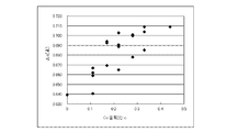
- FIG. 5 is a scatter diagram showing the relationship between the Co content ratio c and ⁇ c for the results in Table 1.
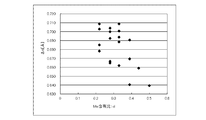
- FIG. 5 is a scatter diagram showing the relationship between the Mn content ratio d and ⁇ c for the results in Table 1.
- FIG. d) It is a schematic diagram of a process.
- e) It is a schematic diagram of a process.
- FIG. 3 is a diagram in which each composition part is divided from a photograph in which a STEM-EDX image of the metal oxide material of Example 1 and an element map of Ni, Co, and Mn are superimposed.
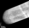
- 2 is a HAADF-STEM image of the metal oxide material of Example 1.
- FIG. 3 is a diagram in which the HAADF-STEM image of the metal oxide material of Example 1 and the elemental maps of Co and Mn obtained by STEM-EDX are superimposed.
- FIG. 2 is a diagram in which the HAADF-STEM image of the metal oxide material of Example 1 and the elemental maps of Co and Mn obtained by STEM-EDX are superimposed, and each composition part is further divided by a solid line.
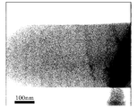
- 2 is a LAADF-STEM image of the metal oxide material of Example 1.
- FIG. 2 is a BF-STEM image of the metal oxide material of Example 1.
- FIG. 3 is an ABF-STEM image of an interface portion between a second composition part and a first composition part of the metal oxide material of Example 1.
- FIG. 2 is an ABF-STEM image of a first composition part of the metal oxide material of Example 1.
- FIG. 3 is an ABF-STEM image of an interface portion between a second composition part and a first composition part of the lithium composite metal oxide of Example 1.
- FIG. 2 is an ABF-STEM image of a first composition part of a lithium composite metal oxide of Example 1.
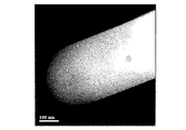
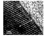
- FIG. 2 is a TEM image of a cross section of the lithium composite metal oxide of Example 1.
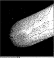
- FIG. 2 is a high-resolution TEM image of a cross section of the lithium composite metal oxide of Example 1.
- FIG. 2 is an FFT diagram of a high manganese part in the lithium composite metal oxide of Example 1.
- FIG. 4 is an FFT diagram of a metal oxide part in the lithium composite metal oxide of Example 1.
- the numerical range “x to y” described in this specification includes the lower limit x and the upper limit y.
- the numerical range can be configured by arbitrarily combining these upper limit value and lower limit value and the numerical values listed in the examples.
- numerical values arbitrarily selected from the numerical value range can be used as upper and lower numerical values.
- Preferred examples of b, c and d include 0 ⁇ b ⁇ 1, 0 ⁇ c ⁇ 1, and 0 ⁇ d ⁇ 1, and more preferably 0 ⁇ b ⁇ 80/100 and 0 ⁇ c ⁇ 70/100. 10/100 ⁇ d ⁇ 1, and 10/100 ⁇ b ⁇ 70/100, 12/100 ⁇ c ⁇ 60/100, 20/100 ⁇ d ⁇ 70/100.
- the ranges of 25/100 ⁇ b ⁇ 60/100, 15/100 ⁇ c ⁇ 50/100, and 25/100 ⁇ d ⁇ 60/100 are particularly preferable.
- D is selected from Fe, Cr, Cu, Zn, Ca, Mg, Zr, S, Si, Na, K, Al, Ti, P, Ga, Ge, V, Mo, Nb, W, La, Hf, Rf At least one element, and preferable D is at least one element selected from Zr, Si, Al, Ti, Ga, Ge, V, Nb, La, Hf, and Rf, and more preferable D is Zr, Si, Ti , Ge, Hf, and Rf, and more preferable D is at least one element selected from Zr, Ti, Hf, and Rf.
- the portion other than the high manganese portion and the metal oxide portion may have a single composition, but may have a plurality of compositions. It may be composed of parts.
- each of the first composition part and the second composition part may be localized or delocalized. Furthermore, the first composition part and the second composition part may form active material primary particles as a single crystal structure.
- the single crystal structure means that the crystal structures of the first composition part and the second composition part are substantially the same, and the crystal orientations of both are continuous in substantially the same direction. Although they are adjacent to each other and have a partially different composition, they are as if they were in a single crystal state.
- the core part is a combined body in which a large number of particles composed of the active material primary particles and the other first composition part and / or second composition part are combined.
- the shape of the active material primary particles is not particularly limited, but many flat particles are observed.
- the major axis length of the active material primary particles is approximately in the range of 100 to 1200 nm, and the minor axis length of the active material primary particles is approximately in the range of 100 to 500 nm. It is.
- the “major axis length of the active material primary particles” means the length of the longest portion of the active material primary particles when the active material primary particles are observed.
- the “short diameter length of the active material primary particles” means the length of the longest portion in the orthogonal direction of the long diameter in the active material primary particles when the active material primary particles are observed.
- the ranges are 100, 12/100 ⁇ c1 ⁇ 80/100, 10/100 ⁇ d1 ⁇ 60/100, 15/100 ⁇ b1 ⁇ 70/100, 15/100 ⁇ c1 ⁇ 70/100, More preferably, the range is 12/100 ⁇ d1 ⁇ 50/100.
- a1, e1, f1 what is necessary is just a numerical value within the range prescribed
- ⁇ B2 ⁇ 1, 0 ⁇ c2 ⁇ c1, d1 ⁇ d2 ⁇ 1 are preferable, and both of c2 ⁇ c1 and d2> d1 may be satisfied.
- at least one of b2, c2, and d2 is in the range of 0 ⁇ b2 ⁇ b1, 0 ⁇ c2 ⁇ c1, d1 ⁇ d2 ⁇ 1, 10/100 ⁇ b2 ⁇ b1, 10/100 ⁇ .
- the ranges are c2 ⁇ c1, d1 ⁇ d2 ⁇ 90/100, 10/100 ⁇ b2 ⁇ 90/100, 10/100 ⁇ c2 ⁇ c1- (5/100), d1 + (5/100) ⁇ D2 ⁇ 90/100 is more preferable, and 12/100 ⁇ b2 ⁇ 80/100, 10/100 ⁇ c2 ⁇ c1- (10/100), d1 + (10/100) ⁇ d2 ⁇ 90 / A range of 100 is particularly preferred.
- the values a2, e2, and f2 may be numerical values within the range defined by the general formula, and preferably 0.5 ⁇ a2 ⁇ 1.3, 0 ⁇ e2 ⁇ 0.2, 1.8 ⁇ f2 ⁇ 2.1. More preferably, 0.8 ⁇ a2 ⁇ 1.2, 0 ⁇ e2 ⁇ 0.1, 1.9 ⁇ f2 ⁇ 2.05 can be exemplified.
- the mass ratio of the first composition part to the second composition part in the core part is preferably in the range of 1:10 to 10: 1, and the preferred range is 1: 5 to 5: 1, 1: 3 to 3: 1, 2. : 5 to 5: 2, 1: 2 to 2: 1, 3: 5 to 5: 3, 7:10 to 10: 7, 4: 5 to 5: 4, and 9:10 to 10 : Especially within the range of 9.
- the present inventor has a c-axis lattice when 67% of Li is desorbed from the lithium composite metal oxide.
- the constant change amount ⁇ c ( ⁇ ) was calculated using the first principle calculation under the following conditions. The results are shown in Table 1. Moreover, the scatter diagram which showed the relationship between Co content ratio c and (DELTA) c, and the scatter diagram which showed the relationship between Mn content ratio d and (DELTA) c are shown in FIG.1 and FIG.2, respectively.
- FIG. 1 shows that the smaller the Co content ratio c of the lithium composite metal oxide, the smaller the tendency of ⁇ c.
- FIG. 2 shows that the larger the Mn content ratio d of the lithium composite metal oxide, the smaller the tendency of ⁇ c.
- the second composition part of the core part has a smaller Co content ratio than the first composition part or a larger Mn content ratio than the first composition part. From the composition relationship between the first composition part and the second composition part and the first principle calculation result, it can be said that the second composition part has a smaller ⁇ c than the first composition part. And the smaller the ⁇ c is, the smaller the amount of crystal deformation of the lithium composite metal oxide during charge / discharge, so the deterioration during charge / discharge is suppressed. Therefore, it can be said that it has been theoretically confirmed that the second composition part is more stable during charge and discharge than the first composition part.
- the c-axis expansion occurring in the first composition part can be suppressed from being excessive, and the c-axis expansion is reduced. Since it is buffered by the second composition part, it is considered that the deterioration of the entire lithium composite metal oxide is alleviated.
- the active material primary particle which consists of a 1st composition part and a 2nd composition part is a single crystal structure, the expansion which arises in a 1st composition part is directly buffered in a 2nd composition part, and the active material 1 Deterioration of secondary particles is suppressed. As a result, it is considered that the deterioration of the entire lithium composite metal oxide is preferably alleviated.
- the present inventor when the manganese composition ratio Mn d2 of the second composition part in the core part is higher than the manganese composition ratio Mn d1 of the first composition part, the doping ratio of the doping elements D e1 and D e2 , It has been found that the first composition part is higher. That is, when d2> d1, e1> e2. It was found that a lithium ion secondary battery using a lithium composite metal oxide satisfying this relationship as an active material has a long life.
- the high manganese part has a higher manganese composition ratio than the core part.
- Ni Li is most active during Li charge / discharge reaction. The capacity increases as the Ni content in the active material increases. On the other hand, the active material tends to deteriorate as the Ni content in the active material increases.
- Mn Most inactive during Li charge / discharge reaction. The capacity decreases as the Mn content increases in the active material. On the other hand, the crystal structure of the active material is more stable as the Mn content increases in the active material.
- Li charge / discharge reaction is intermediate between Ni and Mn.
- capacity and the degree of stability with respect to the content in the active material are also intermediate between Ni and Mn.
- the high manganese part with a high manganese composition ratio is relatively more stable than the core part.
- the high manganese part with a high manganese composition ratio exists in the surface layer of the lithium composite metal oxide of the present invention, the direct contact between the electrolyte and the core part can be suppressed, so that the core that acts as an active material is exhibited. The stability of the part is improved.
- the high manganese part is present in the surface layer of the lithium composite metal oxide of the present invention.
- the high manganese part is present in the surface layer regardless of the amount. As long as the high manganese portion exists in the surface layer, the stability of the lithium composite metal oxide inside is maintained at least as compared with the location where the high manganese portion exists, and as a result, the effect of maintaining the capacity is exhibited.
- the high manganese part is preferably present in the entire surface layer of the lithium composite metal oxide from the viewpoint of maintaining the capacity.
- the surface layer means a layer including the surface of the lithium composite metal oxide of the present invention. From the viewpoint of the stability of the lithium composite metal oxide of the present invention and the core part, it can be said that the thickness of the surface layer is preferably thick, but if the thickness is sufficient to prevent the contact between the electrolyte and the core part, it is practically used. There is no problem. Considering the ease of progress of the Li charge / discharge reaction, it is preferable that the thickness of the surface layer is thin.
- the surface layer thickness t (nm) is, for example, 0 ⁇ t ⁇ 20, preferably 0.01 ⁇ t ⁇ 10, and more preferably 0.1 ⁇ t ⁇ 5.
- the high manganese part may be scattered in the surface layer or may exist as a layer.
- the thickness s 1 (nm) of the layer of the high manganese part is, for example, 0 ⁇ s 1 ⁇ 20, preferably 0.01 ⁇ s 1 ⁇ 10, and more preferably 0.1 ⁇ s 1 ⁇ 5.
- the high manganese portion is located in the range of at least 10 nm from the surface of the lithium composite metal oxide toward the center.
- the high manganese part is preferably in a state of covering the surface of the core part in layers, and the high manganese part is more preferably in the state of covering the entire surface of the core part.
- the values of g, h and i of the high manganese part are not limited as long as the above conditions are satisfied.
- G is preferably in the range of 0 ⁇ g ⁇ 80/100, more preferably in the range of 20/100 ⁇ g ⁇ 70/100, and even more preferably in the range of 25/100 ⁇ g ⁇ 50/100. Further, g is preferably in the range of 0.5 ⁇ b ⁇ g ⁇ 2 ⁇ b, more preferably in the range of 0.8 ⁇ b ⁇ g ⁇ 1.4 ⁇ b, and 0.85 ⁇ b ⁇ g ⁇ 1.1. The range of xb is more preferable, and the range of 0.88 ⁇ b ⁇ g ⁇ 0.96 ⁇ b is particularly preferable.
- H is more preferably in the range of 5/100 ⁇ h ⁇ c, and more preferably in the range of 10/100 ⁇ h ⁇ 25/100. H is preferably in the range of 0.2 ⁇ c ⁇ h ⁇ 0.9 ⁇ c, more preferably in the range of 0.5 ⁇ c ⁇ h ⁇ 0.88 ⁇ c, and 0.63 ⁇ c ⁇ h ⁇ 0. A range of .85 ⁇ c is more preferred.
- I is more preferably in the range of 35/100 ⁇ i ⁇ 85/100, and more preferably in the range of 36/100 ⁇ i ⁇ 65/100.
- i is preferably in the range of d ⁇ i ⁇ 85/100, more preferably in the range of d ⁇ i ⁇ 75/100, and further preferably in the range of d ⁇ i ⁇ 65/100.
- i is preferably in the range of d ⁇ i ⁇ 2 ⁇ d, more preferably in the range of 1.1 ⁇ d ⁇ i ⁇ 1.5 ⁇ d, and in the range of 1.2 ⁇ d ⁇ i ⁇ 1.41 ⁇ d. Is more preferable.
- the metal oxide portion is a portion of the metal oxide present in the outermost layer of the high manganese portion. From the analysis results in Evaluation Example 5 described later, it is presumed that the metal oxide portion is a metal oxide having a metal M selected from Ni, Co, and Mn and is represented by a composition formula different from that of the high manganese portion. It is presumed that the metal oxide portion is represented by a composition formula of Li q M 2 O 3 + r (0 ⁇ q ⁇ 1, 0 ⁇ r ⁇ 1). The range of r is estimated to be 0 ⁇ r ⁇ 1, but may be 0 ⁇ r ⁇ 0.5 or 0 ⁇ r ⁇ 0.3. Moreover, it is estimated that a metal oxidation part acts as a protective film with respect to a high manganese part.
- the metal oxide part Even if the metal oxide part is crystalline or amorphous, the metal oxide part exhibits a function as a protective film. However, since the metal oxide part has better stability than the crystal, the metal oxide part preferably exhibits a protective action.
- the metal oxide portion is present on the outermost layer of the high manganese portion” means that the metal oxide portion is present on the outermost layer of the high manganese portion regardless of the amount. As long as the metal oxide portion is present in the outermost layer of the high manganese portion, the stability of the internal high manganese portion is maintained at least as compared with the location where the metal oxide portion is present. From the viewpoint of improving the stability of the high manganese part, the metal oxide part is preferably in a state of covering the surface of the high manganese part in layers, and the metal oxide part is in a state of covering the entire surface of the high manganese part. preferable.
- the thickness is preferably thicker from the viewpoint of stability, but considering the ease of progress of the Li charge / discharge reaction, the thickness is preferably thinner.
- the thickness t 3 (nm) of the metal oxide layer is, for example, 0 ⁇ t 3 ⁇ 10, preferably 0.01 ⁇ t 3 ⁇ 5, more preferably 0.1 ⁇ t 3 ⁇ 3, and 0.3 ⁇ T 3 ⁇ 1 is more preferable, and 0.4 ⁇ t 3 ⁇ 0.8 is most preferable.
- the shape of the lithium composite metal oxide of the present invention is not particularly limited, but in terms of average particle diameter, it is preferably 100 ⁇ m or less, more preferably 1 ⁇ m or more and 50 ⁇ m or less, further preferably 1 ⁇ m or more and 30 ⁇ m or less, and 2 ⁇ m or more. 20 ⁇ m or less is particularly preferable.
- a lithium composite metal oxide having a thickness of less than 1 ⁇ m may cause problems such as easy adhesion to the current collector when the electrode is produced.
- the lithium composite metal oxide exceeds 100 ⁇ m, problems such as affecting the size of the electrode and damaging the separator constituting the secondary battery may occur.
- the average particle diameter in this specification means D50 when measured with a general laser diffraction particle size distribution meter unless otherwise specified.
- the volume occupied by the high manganese part and the metal oxide part is very small compared to the volume of the entire lithium composite metal oxide of the present invention. Therefore, even if the high manganese part and the metal oxide part exist, the composition formula representing the lithium composite metal oxide of the present invention is not substantially changed.
- metal oxide material any one of the following treatments 1 to 5 (hereinafter referred to as “metal oxide material”)
- performing any one of the following treatments 1 to 5 on the metal oxide material is sometimes referred to as “surface modification.”
- the aqueous solution used in any one of the following treatments 1 to 5 is “ It
- Process 2 2-1) preparing an ammonium phosphate aqueous solution; 2-2) mixing the ammonium phosphate aqueous solution with the above materials, 2-3) A step of mixing the liquid obtained in the step 2-2) and an acidic metal salt aqueous solution, 2-4) A treatment including a step of isolating the lithium composite metal oxide from the liquid obtained in the step 2-3).
- Step 31) Step of preparing an aqueous solution of ammonium phosphate, or an aqueous solution of metal salt and ammonium phosphate 3-2) Step of mixing the aqueous solution and the above materials, 3-3) A treatment including a step of isolating the lithium composite metal oxide from the liquid obtained in the step 3-2).
- Process 4 4-1) preparing an acidic metal salt aqueous solution and an ammonium phosphate aqueous solution, 4-2) a step of mixing water and the above materials, 4-3) A step of mixing the liquid obtained in the step 4-2), the metal salt aqueous solution, and the ammonium phosphate salt aqueous solution, 4-4) A treatment including a step of isolating the lithium composite metal oxide from the liquid obtained in the step 4-3).
- Treatment 1 An acidic metal salt aqueous solution is prepared, and a metal oxide material is added and stirred to obtain a mixed dispersion solution. Next, an aqueous ammonium phosphate solution is further added and stirred while the above mixed dispersion solution is stirred. Stirring is continued for about 15 minutes to 1 hour.
- the lithium composite metal oxide of the present invention is isolated by filtration.
- Treatment 2 Ammonium phosphate aqueous solution is prepared, and a metal oxide material is added and stirred to obtain a mixed dispersion solution. Next, an acidic metal salt aqueous solution is further added and stirred while the above mixed dispersion solution is stirred. Stirring is continued for about 15 minutes to 1 hour.
- the lithium composite metal oxide of the present invention is isolated by filtration.
- Treatment 3 Prepare an aqueous solution of ammonium phosphate, or an aqueous solution of metal salt and ammonium phosphate, add the metal oxide material all at once, and stir. Stirring is continued for about 15 minutes to 1 hour.
- the lithium composite metal oxide of the present invention is isolated by filtration.
- Treatment 4 Prepare an acidic metal salt aqueous solution and an ammonium phosphate salt aqueous solution, respectively.
- the metal oxide material is stirred in ion-exchanged water to obtain a mixed dispersion solution.
- the two types of aqueous solutions are added to the mixed dispersion solution, respectively, or simultaneously and stirred.
- the lithium composite metal oxide of the present invention is isolated by filtration.
- Process 5 A metal phosphate aqueous solution or a metal polyphosphate aqueous solution is prepared. The aqueous solution and the metal oxide material are mixed and stirred to obtain a mixed dispersion solution. Stirring is continued for about 15 minutes to 1 hour. The lithium composite metal oxide of the present invention is isolated by filtration.
- the metal salt used in the treatment 1 to the treatment 4 is preferably a metal nitrate that has little influence on the battery even if it remains in the active material.
- the metal nitrate include magnesium nitrate, barium nitrate, strontium nitrate, aluminum nitrate, and cobalt nitrate.
- ammonium phosphate salt used in treatment 1 to treatment 4 examples include diammonium hydrogen phosphate, ammonium dihydrogen phosphate, and ammonium phosphate, and diammonium hydrogen phosphate is particularly preferable.
- Examples of a method for preparing an aqueous solution of ammonium phosphate include diammonium hydrogen phosphate, ammonium dihydrogen phosphate, or a method of dissolving ammonium phosphate in water, a method of mixing phosphoric acid and ammonia, and the like. be able to.
- the aqueous ammonium phosphate solution used in treatment 1 to treatment 4 is preferably weakly alkaline.
- the concentration of the metal salt aqueous solution, the ammonium phosphate salt aqueous solution, and the aqueous solution containing the metal salt and the ammonium phosphate salt used in the treatments 1 to 4 are not particularly limited.
- the aqueous metal salt solution preferably has a metal salt content in the range of 0.2 to 10% by mass.
- the aqueous ammonium phosphate salt preferably has an ammonium phosphate salt content in the range of 0.2 to 50% by mass.
- the aqueous solution containing a metal salt and an ammonium phosphate salt preferably has a metal salt and an ammonium phosphate salt in the range of 0.2 to 10% by mass.
- Examples of the metal phosphate or metal polyphosphate used in the treatment 5 include magnesium, barium, strontium, aluminum, and cobalt.
- Examples of the phosphate anion constituting the metal phosphate include H 2 PO 4 ⁇ , HPO 4 2 ⁇ , and PO 4 3 ⁇ .
- Polyphosphoric acid is represented by HO— (HPO 3 ) n—H (n is an integer of 2 or more).
- a preferred metal polyphosphate is Mg pyrophosphate.
- the metal phosphate aqueous solution or metal polyphosphate aqueous solution of treatment 5 preferably contains a metal phosphate or metal polyphosphate at a concentration of 0.01 to 15% by mass, and a concentration of 0.1 to 5% by mass. Is more preferable, a concentration of 0.2 to 1% by mass is further preferable, and a concentration of 0.3 to 0.5% by mass is particularly preferable.
- the lithium composite metal oxide of the present invention may be dried and / or fired. Drying is a process for removing water adhering to the lithium composite metal oxide of the present invention, and it may be performed at 80 to 150 ° C. for 1 to 24 hours or 1 to 10 hours, and is performed under reduced pressure conditions. Is also effective. Firing is a process for adjusting the crystallinity of the lithium composite metal oxide of the present invention, and is carried out within a range of 400 to 1200 ° C., 500 to 1000 ° C. or 600 to 900 ° C. for 1 to 10 hours or 1 to 5 hours. Just do it. You may grind
- the formation of high manganese parts and metal oxide parts by surface modification and the thickness of these layers are determined by, for example, transmission electron microscopy and energy dispersive X-ray spectroscopic analysis of the cut surface obtained by cutting the lithium composite metal oxide of the present invention. It can be confirmed and measured by measuring with a TEM-EDX combined with a device and analyzing the composition. When the cut surface of the lithium composite metal oxide of the present invention is observed, it can be seen that the metal oxide portion, the high manganese portion, and the core portion are present in this order from the surface layer side.
- each part is crystalline or amorphous, it can be confirmed by, for example, an FFT figure expressed by fast Fourier transform of an electron beam diffraction pattern obtained by TEM. In addition, it may be possible to determine whether each part is crystalline from the observation of a TEM image.
- the technique of the present invention is completely different from the technique of simply adding Mn or a Mn-containing compound to the material and depositing it on or near the material surface.
- the aqueous solution for surface modification and the lithium composite metal oxide were separated in the above treatments 1 to 5, and P and Mg derived from the aqueous solution for surface modification were not detected from the active materials of the following reference examples.
- the lithium composite metal oxide and the production method of the present invention are completely different from the active material coated with the phosphorus-containing layer disclosed in, for example, JP-A-2003-7299 and the production method thereof. It is.
- the Mn composition ratio of the high manganese part becomes higher than the Mn composition ratio of the core part, but the Co composition ratio becomes low.
- the Ni composition ratio may be high or low.
- Co 1 in the vicinity of the surface layer of the metal oxide material is eluted in the aqueous solution by the treatments 1 to 5 (in some cases, Ni is also eluted in the aqueous solution).
- Ni is also eluted in the aqueous solution.
- the high manganese part has the general formula: Li a3 Ni b3 Co c3 Mn d3 De3O f3 (0.2 ⁇ a3 ⁇ 1.5, b3 + c3 + d3 + e3 ⁇ 1, 0 ⁇ b3 ⁇ b, 0 ⁇ c3 ⁇ c, 0 ⁇ d3 ⁇ d, 0 ⁇ e3 ⁇ 1, D is at least one element selected from Li, Fe, Cr, Cu, Zn, Ca, Mg, Zr, S, Si, Na, K, and Al 1.7 ⁇ f3 ⁇ 2.1).
- the lithium composite metal oxide of the present invention is understood to have been obtained by changing the surface layer of the raw metal oxide material into a high manganese part and a metal oxide part, that is, a surface modification of the metal oxide material. it can.
- the metal oxide material may be produced in accordance with a conventional known production method using a metal salt such as a metal oxide, a metal hydroxide or a metal carbonate, and a doping element D-containing compound, and is commercially available. A thing may be used.
- nickel sulfate, manganese sulfate and cobalt sulfate for example, the following may be performed (coprecipitation method).
- a sulfuric acid aqueous solution containing nickel sulfate, cobalt sulfate and manganese sulfate in predetermined amounts is made alkaline to obtain a coprecipitation slurry, which is dried to obtain a nickel cobalt manganese composite hydroxide.
- a metal oxide material can be obtained by mixing a nickel cobalt manganese composite hydroxide with a predetermined amount of lithium carbonate and a doping element D-containing compound and firing the mixture. The metal oxide material may be appropriately pulverized to obtain a desired particle size.
- the metal oxide material is a solid phase method for a mixed raw material comprising a lithium raw material containing Li, a metal raw material containing at least one selected from Ni, Mn, and Co, and a doping element D-containing compound. Further, it can also be produced by using a known method such as a spray drying method, a hydrothermal method, or a molten salt method.
- the solid phase method is a method of obtaining a metal oxide material by mixing and pulverizing powders of a mixed raw material, drying and compacting as necessary, and heating and firing.
- each raw material is mixed in a proportion corresponding to the composition of the metal oxide material to be manufactured.
- the heating temperature of the raw material mixture in the solid phase method is preferably 900 ° C. or higher and 1000 ° C. or lower, and the heating time is preferably 8 hours or longer and 24 hours or shorter.
- the spray drying method is a method in which powder of a mixed raw material is dissolved in a liquid to form a solution, and the solution is sprayed into the air to form a mist, and the mist solution is heated.
- the heating temperature in the spray drying method is preferably 500 ° C. or more and 1000 ° C. or less, and the heating time is preferably 3 hours or more and 8 hours or less.
- the hydrothermal method is a method in which a raw material is mixed with water to form a mixed solution, and the mixed solution is heated under high temperature and high pressure.
- the heating temperature in the hydrothermal method is preferably from 120 ° C. to 200 ° C., and the heating time is preferably from 2 hours to 24 hours.
- the molten salt method is a method in which a mixed raw material containing a lithium raw material is heated to melt the lithium raw material to form a molten salt, and a metal oxide material is synthesized in this molten liquid.
- the lithium raw material serves as a supply source of Li, but it also plays a role in adjusting the oxidizing power of the molten salt.
- the ratio of Li of the metal oxide material to Li of the lithium material may be less than 1 in molar ratio, but is 0.02 or more and less than 0.7. More preferred are 0.03 to 0.5 and 0.04 to 0.25.
- the metal oxide material in the case where the first composition part and the second composition part are localized is appropriately determined with reference to the manufacturing method disclosed in Japanese Patent Application Laid-Open No. 2013-182882 or Japanese Patent Application Laid-Open No. 2013-18283. What is necessary is just to add and dope element D containing compound.
- “delocalization of the first composition part and the second composition part” means the active material disclosed in the above-mentioned Japanese Patent Application Laid-Open No. 2013-182882 or Japanese Patent Application Laid-Open No. 2013-18283. This means that the first composition part and the second composition part are not localized in one place.
- the metal oxide material in the case where the first composition part and the second composition part are delocalized can be produced by the following two production methods.
- Step 2 of preparing a second aqueous solution Step 2 of preparing a second aqueous solution c) Step of preparing a basic aqueous solution g) Supplying the first aqueous solution to the basic aqueous solution, A step of forming first primary particles containing cobalt and manganese in a molar ratio b1 ′: c1 ′: d1 ′ h) a step of heating the first primary particles to form a first dehydrated product i) the base The second aqueous solution into the aqueous solution Feeding and forming second primary particles containing nickel, cobalt and manganese in a
- the molar ratio of nickel, cobalt and manganese in the step a) or b) may be set in accordance with the target molar ratio of nickel, cobalt and manganese in the first composition part or the second composition part.
- the molar ratio of nickel, cobalt, and manganese in the first composition part or the second composition part may change gradually during the manufacturing process such as firing, the nickel, cobalt, and manganese in the first aqueous solution or the second aqueous solution.
- the molar ratio of nickel, cobalt and manganese in the first composition part or the second composition part do not necessarily match.
- the bonded particles in the step and k) the dehydrated bonded particles in the step are the basis of the active material primary particles.
- Examples of the nickel salt used in the steps a) and b) include nickel sulfate, nickel carbonate, nickel nitrate, nickel acetate, and nickel chloride.
- Examples of the cobalt salt used in the step include cobalt sulfate, cobalt carbonate, cobalt nitrate, cobalt acetate, and cobalt chloride.
- Examples of the manganese salt used in this step include manganese sulfate, manganese carbonate, manganese nitrate, manganese acetate, and manganese chloride.
- the preferred metal concentration range of the first aqueous solution or the second aqueous solution is 0.01 to 4 mol / L, more preferably 0.05 to 3 mol / L, still more preferably 0.1 to 2 mol / L, particularly 0.5 to 1.5 mol / L is preferred.
- the first aqueous solution and the second aqueous solution have the same metal concentration because the primary particle formation rates in the step d) are approximately the same.
- the 1st aqueous solution or the 2nd aqueous solution considers that the metal contained in these aqueous solutions precipitates at a next process, the higher concentration is preferable.
- the pH of the basic aqueous solution in step c is preferably in the range of 9 to 14, more preferably in the range of 10 to 13.5, and even more preferably in the range of 11 to 13.
- regulated by this specification says the value at the time of measuring at 25 degreeC.
- the basic compound that can be used is not particularly limited as long as it dissolves in water and exhibits basicity, and examples thereof include alkali metal hydroxides such as ammonia, sodium hydroxide, potassium hydroxide, and lithium hydroxide, sodium carbonate, and carbonate.
- the basic aqueous solution of step c) has at least a buffer capacity.
- a basic compound is included. Examples of the basic compound having a buffering ability include ammonia, alkali metal carbonates, alkali metal phosphates, and alkali metal acetates.
- the step is preferably carried out in a reaction vessel equipped with a stirring device, and more preferably carried out in a reaction vessel equipped with a device capable of introducing an inert gas such as nitrogen or argon. Moreover, the reaction tank provided with the apparatus used as a constant temperature condition is more preferable.
- c) Specific examples of the steps are given below. Water is charged into a reaction vessel equipped with a stirrer, a nitrogen gas introducing device and a heating device, and heated to 40 ° C. Nitrogen gas is introduced into the reaction vessel to create a nitrogen gas atmosphere. An aqueous sodium hydroxide solution and aqueous ammonia are added to the reaction vessel to prepare a basic aqueous solution.
- Step d) is a step in which the first aqueous solution and the second aqueous solution are simultaneously supplied to the basic aqueous solution from different locations to form the first primary particles and the second primary particles simultaneously.
- the first primary particles and the second primary particles are made of metal hydroxides contained in the first aqueous solution and the second aqueous solution, respectively.
- metal ion hydroxides contained in the first aqueous solution or the second aqueous solution are formed, each of these hydroxides forms a particle nucleus, and each primary particle of a certain size is formed. Form.
- Each primary particle is presumed to be in a single crystal state.
- the first primary particles and the second primary particles have a particle length of approximately 1000 nm or less when observed with a microscope, and the range thereof is approximately 80 to 1000 nm.
- particle length means the length of the longest portion of each particle at the time of observation.
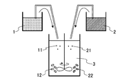
- FIG. 3 A schematic diagram of the process is shown in FIG.
- the first aqueous solution 1 and the second aqueous solution 2 are simultaneously supplied to the basic aqueous solution 3, respectively.
- the metal ion contained in the 1st aqueous solution 1 becomes a hydroxide in the basic aqueous solution 3, the 1st particle nucleus 11 is formed, and the 1st primary particle 12 of a fixed magnitude
- metal ions contained in the second aqueous solution 2 become hydroxides in the basic aqueous solution 3 to form second particle nuclei 21, and second primary particles 22 having a certain size are formed.
- the step is preferably performed under the same conditions as described in step c).
- the stirring speed and temperature conditions may be appropriately set within a range suitable for nucleation and primary particle formation.
- Preferable stirring speed is 50 to 10,000 rpm, more preferably 100 to 3000 rpm, and still more preferably 200 to 1500 rpm.
- the basic compound employed in step c) is included.
- An aqueous solution may be appropriately supplied to maintain a pH and ammonia concentration suitable for nucleation and primary particle formation.
- the supply rate of the first aqueous solution and the supply rate of the second aqueous solution are preferably constant.
- a preferable supply rate is 1 to 30 mL / min. More preferably 1.5 to 15 mL / min. More preferably 2 to 8 mL / min. Can be mentioned.
- the step is a step of forming bonded particles in which the first primary particles and the second primary particles are bonded to each other. Specifically, it is a step of continuously holding and / or stirring while reducing the liquid in step d) as necessary.
- the step e) is preferably performed continuously with the step d).
- a first aqueous solution, a second aqueous solution, and an aqueous solution containing a basic compound may be appropriately supplied. It may be difficult to strictly distinguish between the step e) and the step d). From the relationship of the solubility of each particle, it is preferable to carry out the step e) with a smaller amount of liquid than the step d).
- step e) it is preferable to hold and / or stir the liquid until the desired size of the binding particles is obtained.
- the binding particles have a particle length of approximately 20 ⁇ m or less when observed with a microscope, and the particle length range is approximately 2 to 20 ⁇ m.
- the resulting bonded particles can be separated by filtration.
- the bound particles after separation may be subjected to step e) again as necessary.
- the bound particles after separation are preferably dehydrated under heating conditions. Examples of heating conditions include 100 to 400 ° C. and 1 to 50 hours.
- the bonded particles in which the first primary particles or the second primary particles are bonded are also included. May be obtained. In some cases, a bonded particle in which a plurality of bonded particles are bonded is obtained.
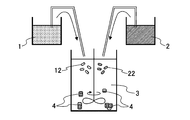
- FIG. 4 A schematic diagram of the process is shown in FIG. As shown in FIG. 4, the first primary particles 12 and the second primary particles 22 are bonded to each other by the collision of the first primary particles 12 and the second primary particles 22 by stirring. Particles 4 are formed.
- Step is a step of obtaining the metal oxide material by mixing and baking the binding particles and the lithium salt obtained in step e).
- the lithium salt include lithium carbonate, lithium hydroxide, lithium nitrate, lithium acetate, lithium oxalate, and lithium halide. What is necessary is just to determine suitably the compounding quantity of lithium salt so that it may become an active material of a desired lithium composition.
- the lithium salt is used so that the molar ratio of lithium to the total of nickel, cobalt, and manganese is in the range of 0.2: 1 to 1.2: 1 in the entire raw material used in step f). What is necessary is just to determine the compounding quantity of.
- Examples of the mixing device include a mortar and pestle, a stirring mixer, a V-type mixer, a W-type mixer, a ribbon-type mixer, a drum mixer, and a ball mill.
- the firing conditions may be set as appropriate within a range of 500 to 1000 ° C. and 1 to 20 hours, for example.
- the firing temperature may be changed during firing, and firing may be performed at a plurality of temperatures.
- suitable firing conditions include performing primary firing under conditions of 600 to 800 ° C. for 8 to 12 hours, and then performing secondary firing under conditions of 800 to 1000 ° C. for 3 to 7 hours. it can. It is preferable that the metal oxide material obtained after firing has a constant particle size distribution through a pulverization step and a classification step.
- the average particle diameter (D50) is preferably 100 ⁇ m or less, more preferably 1 ⁇ m or more and 50 ⁇ m or less, and even more preferably 1 ⁇ m or more and 30 ⁇ m or less in the measurement with a general laser scattering diffraction particle size distribution analyzer. 2 ⁇ m or more and 20 ⁇ m or less is particularly preferable.
- the step D1) is a step of adding the doping element D-containing compound at any time point among the steps a) to e) or before the firing of the step f). What is necessary is just to determine suitably the compounding quantity of dope element D containing compound so that it may become desired dope amount ( De ).
- the doping element D-containing compound include doping element D oxide, doping element D hydroxide, doping element D sulfate, doping element D nitrate, doping element D phosphate, and doping element D halide.
- the doping element D is zirconium
- specific examples include zirconium oxide, zirconium hydroxide, zirconium sulfate, zirconium nitrate, zirconium phosphate and zirconium halide.
- steps g) to l) and step D2) of the second production method will be described.
- Step g) is a step of forming the first primary particles by supplying the first aqueous solution to the basic aqueous solution.
- Each condition of a process may be the conditions which excluded the location about the 2nd aqueous solution and the 2nd primary particle from explanation of the above-mentioned d) process.
- Step h) is a step in which the first primary particles made of the metal hydroxide obtained in step g) are heated to form a first dehydrated product.
- heating conditions include 100 to 400 ° C. and 1 to 50 hours.
- Step i) is a step in which the second aqueous solution is supplied to the basic aqueous solution prepared in step c) to form second primary particles.
- Each condition of the process may be a condition excluding the part relating to the first aqueous solution and the first primary particles from the description of the above d) process.
- Step j) is a step in which the second primary particles made of the metal hydroxide obtained in step i) are heated to form a second dehydrated product.
- heating conditions include 100 to 400 ° C. and 1 to 50 hours.
- Step k) is a step of producing dehydrated bonded particles in which the first dehydrated product and the second dehydrated product are bonded to each other by mixing the first dehydrated product and the second dehydrated product in the particle compounding apparatus.
- the particle composite apparatus include a hybridization system (NHS) and Miraro (NARA) manufactured by Nara Machinery Co., Ltd., Mechano-Fusion and Nobilta manufactured by Hosokawa Micron Co., Ltd., and theta composer manufactured by Tokuju Works.
- the step is a step in which dehydrated bonded particles and lithium salt are mixed and fired to obtain a metal oxide material, and the specific conditions are the same as those in step f).
- Step D2) is a step of adding the doping element D-containing compound at any time before firing in any one of steps a) to c) and g) to k) or l). Specific conditions are the same as in step D1).
- a lithium ion secondary battery can be manufactured using the lithium composite metal oxide of the present invention.
- the lithium ion secondary battery including the lithium composite metal oxide of the present invention may be referred to as “the lithium ion secondary battery of the present invention”.
- the lithium ion secondary battery of this invention contains a negative electrode, a separator, and electrolyte solution as a battery component in addition to the electrode (for example, positive electrode) which has the lithium composite metal oxide of this invention.
- the positive electrode is composed of a current collector and an active material layer containing the lithium composite metal oxide of the present invention as an active material.
- the active material layer may contain an active material other than the lithium composite metal oxide of the present invention.
- a current collector refers to a chemically inert electronic high conductor that keeps a current flowing through an electrode during discharge or charging of a lithium ion secondary battery.
- the current collector at least one selected from silver, copper, gold, aluminum, magnesium, tungsten, cobalt, zinc, nickel, iron, platinum, tin, indium, titanium, ruthenium, tantalum, chromium, molybdenum, and stainless steel Examples of such a metal material can be given.
- the current collector may be covered with a known protective layer.
- the current collector can take the form of a foil, a sheet, a film, a line, a bar, or the like. Therefore, metal foils, such as copper foil, nickel foil, aluminum foil, stainless steel foil, can be used suitably as a collector.
- the thickness is preferably in the range of 10 ⁇ m to 100 ⁇ m.
- a positive electrode can be obtained by forming an active material layer on the surface of the current collector.
- the active material layer may contain a conductive aid.
- the conductive assistant is added to increase the conductivity of the electrode.
- Examples of the conductive assistant include carbon black, graphite, acetylene black (AB), ketjen black (KB), and vapor grown carbon fiber (Vapor Grown Carbon Fiber: VGCF). .
- These conductive assistants can be added to the active material layer alone or in combination of two or more.
- the amount of the conductive auxiliary agent used is not particularly limited, but can be, for example, 1 to 50 parts by mass or 1 to 30 parts by mass with respect to 100 parts by mass of the active material.
- the active material layer may contain a binder.
- the binder serves to bind the active material and the conductive additive to the surface of the current collector.
- the binder include fluorine-containing resins such as polyvinylidene fluoride, polytetrafluoroethylene, and fluororubber, thermoplastic resins such as polypropylene and polyethylene, imide resins such as polyimide and polyamideimide, and alkoxysilyl group-containing resins. be able to.
- the amount of the binder used is not particularly limited, but can be, for example, 5 to 50 parts by mass with respect to 100 parts by mass of the active material.
- an active material layer on the surface of the current collector As a method of forming an active material layer on the surface of the current collector, a conventionally known method such as a roll coating method, a dip coating method, a doctor blade method, a spray coating method, or a curtain coating method is used.
- An active material may be applied to the surface. Specifically, an active material layer-forming composition containing an active material and, if necessary, a binder and a conductive aid is prepared, and an appropriate solvent is added to the composition to make a paste, and then the collection is performed. After applying to the surface of the electric body, it is dried. If necessary, the dried product may be compressed to increase the electrode density.
- solvent examples include N-methyl-2-pyrrolidone (NMP), methanol, and methyl isobutyl ketone (MIBK).
- NMP N-methyl-2-pyrrolidone
- MIBK methyl isobutyl ketone
- the negative electrode has a current collector and a negative electrode active material layer bound to the surface of the current collector.
- the negative electrode active material layer contains a negative electrode active material and, if necessary, a binder and / or a conductive aid.
- the current collector, binder and conductive additive are the same as those described for the positive electrode.
- Examples of the negative electrode active material include a carbon-based material capable of inserting and extracting lithium, an element that can be alloyed with lithium, a compound having an element that can be alloyed with lithium, a polymer material, and the like.
- the carbon-based material examples include non-graphitizable carbon, artificial graphite, cokes, graphites, glassy carbons, organic polymer compound fired bodies, carbon fibers, activated carbon, and carbon blacks.
- the organic polymer compound fired body refers to a material obtained by firing and carbonizing a polymer material such as phenols and furans at an appropriate temperature.
- elements that can be alloyed with lithium include Na, K, Rb, Cs, Fr, Be, Mg, Ca, Sr, Ba, Ra, Ti, Ag, Zn, Cd, Al, Ga, In, Si. , Ge, Sn, Pb, Sb, Bi can be exemplified, and Si or Sn is particularly preferable.
- Specific examples of compounds having elements that can be alloyed with lithium include ZnLiAl, AlSb, SiB 4 , SiB 6 , Mg 2 Si, Mg 2 Sn, Ni 2 Si, TiSi 2 , MoSi 2 , CoSi 2 , NiSi 2 , CaSi 2, CrSi 2, Cu 5 Si, FeSi 2, MnSi 2, NbSi 2, TaSi 2, VSi 2, WSi 2, ZnSi 2, SiC, Si 3 N 4, Si 2 N 2 O, SiO v (0 ⁇ v ⁇ 2), SnO w (0 ⁇ w ⁇ 2), SnSiO 3 , LiSiO 2 or LiSnO, particularly SiO x (0.3 ⁇ x ⁇ 1.6, or 0.5 ⁇ x ⁇ 1.5) Is preferred.
- the negative electrode active material preferably includes a Si-based material having Si.
- the Si-based material may be made of silicon or / and a silicon compound capable of occluding / releasing lithium ions, for example, SiOx (0.5 ⁇ x ⁇ 1.5).
- SiOx 0.5 ⁇ x ⁇ 1.5
- silicon has a large theoretical charge / discharge capacity
- silicon has a large volume change during charge / discharge. Therefore, the volume change of silicon can be mitigated by using SiOx containing silicon as the negative electrode active material.
- the Si-based material preferably has a Si phase and a SiO 2 phase.
- the Si phase is composed of simple silicon, and is a phase that can occlude and release Li ions, and expands and contracts as Li ions are occluded and released.
- the SiO 2 phase is made of SiO 2 and serves as a buffer phase that absorbs the expansion and contraction of the Si phase.
- a Si-based material in which the Si phase is covered with the SiO 2 phase is preferable.
- it is preferable that a plurality of micronized Si phases are covered with a SiO 2 phase to form particles integrally. In this case, the volume change of the entire Si-based material can be effectively suppressed.
- the mass ratio of the SiO 2 phase to the Si phase in the Si-based material is preferably 1 to 3.
- the mass ratio is less than 1, the expansion and contraction of the Si-based material increases, and the negative electrode active material layer containing the Si-based material may be cracked.
- the mass ratio exceeds 3, the amount of occlusion and release of Li ions of the negative electrode active material decreases, and the electric capacity per unit negative electrode mass of the battery decreases.
- a tin compound such as a tin alloy (Cu—Sn alloy, Co—Sn alloy, etc.) can be exemplified.
- polymer material examples include polyacetylene and polypyrrole.
- the separator separates the positive electrode and the negative electrode and allows lithium ions to pass through while preventing a short circuit of current due to contact between the two electrodes.
- the separator include a porous film using one or more synthetic resins such as polytetrafluoroethylene, polypropylene, or polyethylene, or a ceramic porous film.
- the electrolytic solution contains a non-aqueous solvent and an electrolyte dissolved in the non-aqueous solvent.
- cyclic esters examples include ethylene carbonate, propylene carbonate, butylene carbonate, gamma butyrolactone, vinylene carbonate, 2-methyl-gamma butyrolactone, acetyl-gamma butyrolactone, and gamma valerolactone.
- chain esters include dimethyl carbonate, diethyl carbonate, dibutyl carbonate, dipropyl carbonate, methyl ethyl carbonate, propionic acid alkyl ester, malonic acid dialkyl ester, and acetic acid alkyl ester.
- ethers examples include tetrahydrofuran, 2-methyltetrahydrofuran, 1,4-dioxane, 1,2-dimethoxyethane, 1,2-diethoxyethane, and 1,2-dibutoxyethane.
- Examples of the electrolyte include lithium salts such as LiClO 4 , LiAsF 6 , LiPF 6 , LiBF 4 , LiCF 3 SO 3 , and LiN (CF 3 SO 2 ) 2 .
- a lithium salt such as LiClO 4 , LiPF 6 , LiBF 4 , LiCF 3 SO 3 in a nonaqueous solvent such as ethylene carbonate, dimethyl carbonate, propylene carbonate, and dimethyl carbonate.
- a solution dissolved at a concentration of about 1 / l can be exemplified.
- the lithium ion secondary battery of the present invention has a stable high manganese part on the surface of the core part that acts as an active material, and further has a metal oxide part that protects the high manganese part. Indicates the maintenance rate. As a result, the lithium ion secondary battery of the present invention can exhibit a good capacity retention rate even under high potential driving conditions. Therefore, the lithium ion secondary battery of the present invention maintains a large charge / discharge capacity and has excellent cycle performance.
- the high potential driving condition means that the operating potential of lithium ions with respect to lithium metal is 4.3 V or more, and further 4.4 V to 4.6 V or 4.5 V to 5.5 V.
- the charging potential of the positive electrode can be set to 4.3 V or higher, further 4.4 V to 4.6 V or 4.5 V to 5.5 V with respect to lithium. Note that, under the driving conditions of a general lithium ion secondary battery, the operating potential of lithium ions with respect to lithium metal is less than 4.3V.
- the type of the lithium ion secondary battery of the present invention is not particularly limited, and various types such as a cylindrical type, a square type, a coin type, and a laminate type can be adopted.
- the lithium ion secondary battery of the present invention can be mounted on a vehicle. Since the lithium ion secondary battery of the present invention maintains a large charge / discharge capacity and has excellent cycle performance, a vehicle equipped with the lithium ion secondary battery is a high-performance vehicle.
- the vehicle may be a vehicle that uses electric energy from a battery as a whole or a part of a power source.
- a vehicle that uses electric energy from a battery as a whole or a part of a power source.
- an electric vehicle a hybrid vehicle, a plug-in hybrid vehicle, a hybrid railway vehicle, an electric forklift, an electric wheelchair, and an electric assist.
- Bicycles and electric motorcycles are examples.
- Example 1 The lithium composite metal oxide of Example 1 was produced as follows. Nickel sulfate, cobalt sulfate, and manganese sulfate were dissolved in water to prepare a first aqueous solution having a molar ratio of nickel, cobalt, and manganese of 6: 2: 2. The total concentration of nickel, cobalt and manganese in the first aqueous solution was 0.9 mol / L.
- Nickel sulfate, cobalt sulfate, and manganese sulfate were dissolved in water to prepare a second aqueous solution having a molar ratio of nickel, cobalt, and manganese of 4: 2: 4.
- the total concentration of nickel, cobalt and manganese in the second aqueous solution was 0.9 mol / L.
- the first aqueous solution and the second aqueous solution were simultaneously supplied to the basic aqueous solution under stirring conditions at a speed of 1000 rpm.
- the supply rates of the first aqueous solution and the second aqueous solution were 0.4 mL / min. Met.
- a 16 mass% aqueous solution of sodium hydroxide and an aqueous 3 mass% solution of ammonia were added to the reaction vessel. Were appropriately supplied. Then, first primary particles containing nickel, cobalt and manganese in a molar ratio of 6: 2: 2 and second primary particles containing nickel, cobalt and manganese in a molar ratio of 4: 2: 4 were formed.
- the amount of the aqueous solution in the reaction vessel is reduced, and stirring is continued while maintaining the ammonia concentration of the aqueous solution at about 9 g / L and the pH of the aqueous solution at about 11.2 to 11.3. Bonded particles in which primary particles were bonded to each other were formed. After the binding particles were filtered, the amount of the aqueous solution in the reaction vessel was reduced again, and the binding particles were added to the aqueous solution to grow the binding particles. The grown bonded particles were separated by filtration and washed with water. The washed bonded particles were heated at 300 ° C. for 20 hours for dehydration.
- the dehydrated binding particles and lithium carbonate were mixed so that a molar ratio of lithium to the total of nickel, cobalt, and manganese was 1.1: 1 to obtain a mixture.
- 0.5% by mass of zirconium phosphate as a doping element D-containing compound was added and mixed.
- the obtained mixture was subjected to primary firing at 650 ° C. for 10 hours.
- secondary firing was performed at 850 ° C. for 5 hours to obtain a fired product.
- the fired product was cooled, pulverized and classified to obtain a metal oxide material having an average particle size of 6 ⁇ m.
- the metal oxide material has an average composition represented by Li 1.13 Ni 4.97 / 10 Co 1.99 / 10 Mn 2.98 / 10 Zr 0.05 / 10 O 2 . This was used as the metal oxide material of Example 1.
- the following surface modification was performed on the metal oxide material.
- an aqueous solution for surface modification an Mg pyrophosphate aqueous solution containing 0.4% by mass of Mg pyrophosphate was prepared.
- the aqueous solution of Mg pyrophosphate and the metal oxide material were mixed and stirred at room temperature for 1 hour. After stirring, the lithium composite metal oxide was isolated by filtration. Next, the lithium composite metal oxide was dried at 130 ° C. for 6 hours. The lithium composite metal oxide after drying was heated at 700 ° C. in an air atmosphere for 5 hours.
- the product obtained by these treatments was used as the lithium composite metal oxide of Example 1.
- the lithium composite metal oxide has an average composition of Li 1.13 Ni 4.97 / 10 Co 1.99 / 10 Mn 2.98 / 10 Zr 0.05 / 10 O 2 in the same manner as the metal oxide material. It is represented by
- Example 2 A lithium composite metal oxide of Example 2 was obtained in the same manner as in Example 1 except that an aqueous solution of Mg pyrophosphate containing 0.8% by mass of Mg pyrophosphate was used as the surface modification aqueous solution.
- Example 3 A lithium composite metal oxide of Example 3 was obtained in the same manner as in Example 1 except that an aqueous solution of Mg pyrophosphate containing 12.6% by mass of Mg pyrophosphate was used as the surface modification aqueous solution.
- Comparative Example 1 Comparative Example 1 was carried out in the same manner as in Example 1 except that commercially available Li 1.1 Ni 5/10 Co 2/10 Mn 3/10 O 2 not doped with zirconium was used as the metal oxide material. Lithium composite metal oxide was obtained.
- Comparative Example 2 Commercially available Li 1.1 Ni 5/10 Co 2/10 Mn 3/10 O 2 that was not subjected to surface modification was used as the lithium composite metal oxide of Comparative Example 2.
- Example 4 The lithium ion secondary battery of Example 4 was produced as follows.
- the positive electrode was prepared as follows. An aluminum foil having a thickness of 20 ⁇ m was prepared as a positive electrode current collector. 94 parts by mass of the lithium composite metal oxide of Example 1 as an active material, 3 parts by mass of acetylene black as a conductive additive, and 3 parts by mass of polyvinylidene fluoride (PVDF) as a binder were mixed. This mixture was dispersed in an appropriate amount of N-methyl-2-pyrrolidone (NMP) to prepare a slurry. The slurry was placed on the surface of the aluminum foil, and applied using a doctor blade so that the slurry became a film. The aluminum foil coated with the slurry was dried at 80 ° C.
- NMP N-methyl-2-pyrrolidone
- the aluminum foil having the active material layer formed on the surface thereof was compressed using a roll press, and the aluminum foil and the active material layer were firmly bonded.
- the joined product was heated with a vacuum dryer at 120 ° C. for 6 hours, cut into a predetermined shape (rectangular shape of 25 mm ⁇ 30 mm), and a positive electrode having a thickness of about 60 ⁇ m was obtained.
- the negative electrode was produced as follows. Carbon-coated SiO x (0.3 ⁇ x ⁇ 1.6) 32 parts by mass, graphite 50 parts by mass, acetylene black 8 parts by mass as a conductive additive, and polyamideimide 10 parts by mass as a binder, This mixture was dispersed in an appropriate amount of ion-exchanged water to prepare a slurry. This slurry was applied to a copper foil having a thickness of 20 ⁇ m as a negative electrode current collector so as to form a film using a doctor blade, and the current collector coated with the slurry was dried and pressed. Heated with a vacuum dryer for a time, cut into a predetermined shape (rectangular shape of 25 mm ⁇ 30 mm), and made a negative electrode having a thickness of about 85 ⁇ m.
- a laminate type lithium ion secondary battery was manufactured using the positive electrode and the negative electrode. Specifically, a rectangular sheet (27 ⁇ 32 mm, thickness 25 ⁇ m) made of a resin film having a three-layer structure of polypropylene / polyethylene / polypropylene was sandwiched between the positive electrode and the negative electrode to form an electrode plate group. The electrode plate group was covered with a set of two laminated films, and the three sides were sealed, and then an electrolyte solution was injected into the bag-like laminated film.
- the electrolytic solution a solution in which LiPF 6 was dissolved to 1 mol / L in a solvent in which ethylene carbonate, methyl ethyl carbonate, and diethyl carbonate were mixed at a volume ratio of 3: 3: 4 was used. Thereafter, the remaining one side was sealed to obtain a laminate type lithium ion secondary battery of Example 4 in which the four sides were hermetically sealed and the electrode plate group and the electrolyte were sealed.
- the positive electrode and the negative electrode have a tab that can be electrically connected to the outside, and a part of the tab extends to the outside of the laminated lithium ion secondary battery.
- Example 5 A lithium ion secondary battery of Example 5 was produced in the same manner as in Example 4 except that the lithium composite metal oxide of Example 2 was used as the active material.
- Example 6 A lithium ion secondary battery of Example 6 was produced in the same manner as in Example 4 except that the lithium composite metal oxide of Example 3 was used as the active material.
- Comparative Example 3 A lithium ion secondary battery of Comparative Example 3 was produced in the same manner as in Example 4 except that the lithium composite metal oxide of Comparative Example 1 was used as the active material.
- Comparative Example 4 A lithium ion secondary battery of Comparative Example 4 was produced in the same manner as in Example 4 except that the lithium composite metal oxide of Comparative Example 2 was used as the active material.
- FIG. 5 shows an image obtained by STEM-EDX and a photograph obtained by superposing the element maps of Ni, Co, and Mn, in which the first composition part and the second composition part are divided.
- 100 represents the first composition part
- 200 represents the second composition part.
- FIG. 5 shows the analysis of Ni, Co, Mn, and Zr for each point of the first composition part and the second composition part in FIG. 5, and Table 2 shows the obtained metal atom composition ratio (%).
- Ni as the metal element of the first composition part and the second composition part is divalent or trivalent
- Co is trivalent
- Mn is tetravalent
- the doped metal element Zr is easily tetravalent.
- the environment of the base material in which the metal element having a tetravalent charge is easily doped is the same as the base metal element having the same tetravalent charge, that is, Mn does not exist excessively and the tetravalent charge is present.
- the charge of the metal of the entire base material ( It is considered that there is sufficient Ni that can adjust the valence) to trivalent.
- Ni can be changed from trivalent to divalent. Therefore, the first composition part having a relatively low Mn composition ratio and a sufficiently large Ni composition ratio relative to the Mn composition ratio is a doping element having a tetravalent charge as compared with the second composition part. It is thought that Zr easily penetrated into the crystal.
- HAADF-STEM Annular dark-field scanning transmission electron microscope
- JEM-ARM200F JEM-ARM200F
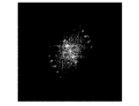
- FIG. 6 The obtained HAADF-STEM image is shown in FIG. In the HAADF-STEM image of FIG. 6, no crystal grain boundary indicating that the crystal orientation is different was observed.
- FIG. 7 is a diagram in which the element maps of Co and Mn obtained by STEM-EDX and the HAADF-STEM image are superimposed. Furthermore, the figure which divided each composition part with the continuous line is shown in FIG.
- the composition parts divided by a solid line in FIG. 8 are, in order from the top, the second composition part, the first composition part, the second composition part, the first composition part, and the second composition part.
- LAADF-STEM low angle scattering annular dark field scanning transmission electron microscope
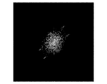
- the cross section of the same active material primary particles as above was measured with a bright field scanning transmission electron microscope (BF-STEM).
- the obtained BF-STEM image is shown in FIG.
- the vertical direction is the orientation ⁇ 0001>
- the horizontal direction is the orientation ⁇ 11-20>.
- “ ⁇ 2” represents 2 with an overline.
- the image of FIG. 10 and the image of FIG. 9 are in the relationship of reversal of the image contrast, and the white line first confirmed in FIG. 9 is observed as a black line in FIG.
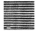
- FIG. 10 shows an ABF-STEM image obtained by measuring the vicinity of the center of the first composition portion with an annular bright field scanning transmission electron microscope.
- each spot indicates an element
- a horizontal spot layer indicates an element layer
- the darkest black spot layer shows a transition metal layer.
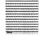
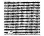
- Each image in FIG. 11 and FIG. 12 is regularly repeated in the order of the transition metal layer, which is the darkest black spot layer, hereinafter, the oxygen layer, the lithium layer, the oxygen layer, and the transition metal layer in the vertical direction. Recognize.
- the layers composed of each element are arranged in a straight line without any disturbance, whereas each layer in FIG. 11 has a very slight arrangement disturbance. I understand. However, no special boundary was observed in the periodic element arrangement of FIG. 11 despite the fact that the composition was switched as confirmed in FIGS. This means that the image of FIG.
- the interface part between the second composition part and the first composition part of the primary particles of the active material is a place where only the transition metal composition is switched without substantially different from other parts from the viewpoint of the crystal lattice.
- the newly observed line due to the diffraction contrast in FIGS. 9 and 10 does not indicate a crystal grain, but a very small amount of primary particles of the active material. It is thought that the disorder of the arrangement was observed as an image, and the cause is presumed to be the distortion generated due to the composition change.
- the active material primary particles composed of the first composition part and the second composition part in the metal oxide material are as if they were single crystals, although there are portions where the compositions are partially different. It was proved that it was a single crystal structure exhibiting a simple state.
- the cross section of the primary particles of the active material was analyzed using STEM-EDX and Zr as a measurement target. As a result, it was confirmed that Zr was present at a higher concentration on the surface layer side than on the inner side of the particles.
- both images show the same crystal structure, although the contrast ratio and the sharpness are different.
- the active material primary particles composed of the first composition part and the second composition part in the lithium composite metal oxide, as with the metal oxide material that is a precursor thereof, have parts that are partially different from each other. It was proved that it was a single crystal structure showing a crystal-like state.
- the vicinity of the surface portion of the cross section was measured with a high resolution TEM.
- a layer having a crystal state different from the core portion and the high manganese portion that is, a metal oxide portion, exists in a layer form on the outermost surface with a width of about 0.5 to 0.7 nm.
- the obtained high resolution TEM image is shown in FIG. In FIG. 16, the layer in the range sandwiched between the upper two arrows corresponds to the metal oxide part, and the layer in the lower center arrow corresponds to the high manganese part.
- the electron diffraction patterns of the high manganese part and the metal oxide part obtained by the high resolution TEM were each subjected to fast Fourier transform to obtain an FFT figure.
- the FFT figure of the high manganese part is shown in FIG. 17, and the FFT figure of the metal oxide part is shown in FIG.
- Each FFT pattern shows a different diffraction pattern, confirming that they are distinct crystal structures.
- the metal oxide portion was analyzed by TEM-EDX, it was found that the metal oxide portion had the same Ni and Co composition ratio, slightly higher Mn composition, and slightly lower oxygen composition than the high manganese portion. found.
- the Mn composition ratio in the range of about 15 nm from the surface of the lithium composite metal oxide was higher than the internal composition ratio. Turned out to be. It can be said that the high manganese portion exists in the range of about 15 nm from the surface of the lithium composite metal oxide. It was also found that a metal oxide portion exists on the outermost surface with a width of about 3 to 5 nm. However, a regular crystal state was not observed in the metal oxide part.
- the FFT figure which carried out the fast Fourier transform of the electron beam diffraction pattern of the core part, high manganese part, and metal oxidation part which were both obtained by high resolution TEM was obtained, the FFT figure of a core part and a high manganese part was respectively specified. It shows a diffraction pattern, and it was confirmed that the core part and the high manganese part are crystalline. However, the diffraction pattern is not observed from the FFT pattern of the metal oxide part, and the metal oxide part is amorphous. Was supported.
- the battery to be measured was charged to 60 ° C., 1 C rate, voltage 4.32 V, and stored at 60 ° C. for 6 days. After storage, the sample was left at room temperature for 5 hours or more, and the discharge capacity was measured under the same conditions as the initial capacity measurement. This was defined as the capacity after storage for 6 days.
- the battery stored for 6 days was charged again to 60 ° C., 1C rate, voltage of 4.32 V, and further stored at 60 ° C. for 6 days.
- the sample was left at room temperature for 5 hours or more, and the discharge capacity was measured under the same conditions as the initial capacity measurement. This was defined as the capacity after storage for 12 days.
- Capacity maintenance rate (%) (Capacity after storage / Initial capacity) ⁇ 100
- the current rate for discharging in 1 hour is called 1C.
- (Reference Example 1) According to the said process 1, the following processes were performed to the lithium composite metal oxide as a starting material.
- the lithium composite metal oxide was immersed in an aqueous solution for surface modification and stirred and mixed at room temperature. The immersion time was 1 hour.
- the lithium ion secondary battery of Reference Example 1 was produced as follows.
- the positive electrode was prepared as follows. An aluminum foil having a thickness of 20 ⁇ m was prepared as a positive electrode current collector. 94 parts by mass of the active material of Reference Example 1, 3 parts by mass of acetylene black as a conductive auxiliary agent, and 3 parts by mass of polyvinylidene fluoride (PVDF) as a binder were mixed. This mixture was dispersed in an appropriate amount of N-methyl-2-pyrrolidone (NMP) to prepare a slurry. The slurry was placed on the surface of the aluminum foil, and applied using a doctor blade so that the slurry became a film. The aluminum foil coated with the slurry was dried at 80 ° C.
- NMP N-methyl-2-pyrrolidone
- the aluminum foil having the active material layer formed on the surface thereof was compressed using a roll press, and the aluminum foil and the active material layer were firmly bonded.
- the joined product was heated with a vacuum dryer at 120 ° C. for 6 hours and cut into a predetermined shape (rectangular shape of 25 mm ⁇ 30 mm) to obtain a positive electrode.
- the negative electrode was produced as follows. 97 parts by mass of graphite, 1 part by mass of KB as a conductive additive, 1 part by mass of styrene-butadiene rubber (SBR) and 1 part by mass of carboxymethylcellulose (CMC) as a binder are mixed, and this mixture is subjected to an appropriate amount of ion exchange. A slurry was prepared by dispersing in water. This slurry was applied to a copper foil having a thickness of 20 ⁇ m as a negative electrode current collector so as to form a film using a doctor blade, and the current collector coated with the slurry was dried and pressed. Heated with a vacuum dryer for a time, cut into a predetermined shape (rectangular shape of 25 mm ⁇ 30 mm), and made a negative electrode having a thickness of about 85 ⁇ m.
- SBR styrene-butadiene rubber
- CMC carboxymethylcellulose
- a laminate type lithium ion secondary battery was manufactured using the positive electrode and the negative electrode. Specifically, a rectangular sheet (27 ⁇ 32 mm, thickness 25 ⁇ m) made of a resin film having a three-layer structure of polypropylene / polyethylene / polypropylene was sandwiched between the positive electrode and the negative electrode to form an electrode plate group. The electrode plate group was covered with a set of two laminated films, and the three sides were sealed, and then an electrolyte solution was injected into the bag-like laminated film.
- the positive electrode and the negative electrode have a tab that can be electrically connected to the outside, and a part of the tab extends to the outside of the laminated lithium ion secondary battery.
- Reference Example 2 An active material and a laminate type lithium ion secondary battery of Reference Example 2 were produced in the same manner as in Reference Example 1, except that the time for immersing the lithium composite metal oxide in the aqueous solution for surface modification was changed to 36 hours. .
- Reference Example 1 was used in the same manner as Reference Example 1 except that the surface modification aqueous solution was changed to one containing 5.4% by mass of (NH 4 ) 2 HPO 4 when the total aqueous solution was 100% by mass. 4 active material and a laminate type lithium ion secondary battery were produced.
- Reference Comparative Example 1 LiNi 1/3 Co 1/3 Mn 1/3 O 2 itself (hereinafter sometimes referred to as “untreated product of Reference Comparative Example 1”) was used as the active material. A laminated lithium ion secondary battery was produced.
- ⁇ Reference Evaluation Example 1> The initial capacities of the laminated lithium ion secondary batteries of Reference Examples 1 to 4 and Reference Comparative Example 1 were measured.
- the battery to be measured is CCCV charged (constant current constant voltage charge) at 25 ° C., 0.33 C rate, voltage 4.5 V, and CC discharge (constant current discharge) is performed at voltage 3.0 V, 0.33 C rate.
- the discharge capacity when measured was measured and used as the initial capacity.
- CCCV charge constant current constant voltage charge
- CC discharge constant current discharge
- voltage 3.0V, 0.33C rate The 4.5V-3.0V charge / discharge cycle to be performed was performed on the battery to be measured for 25 cycles, and then the discharge capacity at the 0.33C rate was measured to calculate the capacity retention rate.
- Capacity retention rate (%) (capacity after cycle / initial capacity) ⁇ 100
- the current rate for discharging in 1 hour is called 1C.
- Table 6 shows the results of the Ni, Co and Mn composition ratios of the surface layer of the active material, the initial capacity, the capacity after 25 cycles, and the capacity retention rate.
- composition ratio of Ni, Co, and Mn on the surface layer of the active material was calculated by measuring the surface of the active material by X-ray photoelectron spectroscopy. The fact that the internal composition ratio of the active material did not change was confirmed by analyzing the internal composition from the particle cross-sectional direction with TEM-EDX. At this time, signals of Mg and P used for surface modification were below the detection limit of the TEM-EDX analysis in the surface layer and inside of the active material. In other words, the surface layer of the active material obtained by surface modification does not exhibit new performance due to the element added from the outside, but the function improvement is achieved by the modification made by the element contained in the active material from the beginning. It can be said that it is demonstrated.
- the Mn composition ratio is high, while the Co composition ratio is low. I understand that.
- the active material when the Mn composition ratio of the surface layer of the active material is made higher than the Mn composition ratio of the original (or internal) active material, the active material exhibits a good capacity retention rate.
- Reference Example 5 A lithium composite metal oxide represented by LiNi 5/10 Co 2/10 Mn 3/10 O 2 prepared by a coprecipitation method was prepared. Hereinafter, each surface modification aqueous solution containing 0.4 mass% of (NH 4 ) 2 HPO 4 and 1.4 mass% of Mg (NO 3 ) 2 when the total aqueous solution is 100 mass%.
- the active material of Reference Example 5 was obtained using the same method as in Reference Example 1 except that
- the positive electrode was prepared in the same manner as in Reference Example 1 except that the active material of Reference Example 5 was used as the active material.
- the negative electrode was produced as follows. Carbon-coated SiO x (0.3 ⁇ x ⁇ 1.6) 32 parts by mass, graphite 50 parts by mass, acetylene black 8 parts by mass as a conductive additive, and polyamideimide 10 parts by mass as a binder, This mixture was dispersed in an appropriate amount of ion-exchanged water to prepare a slurry. This slurry was applied to a copper foil having a thickness of 20 ⁇ m as a negative electrode current collector so as to form a film using a doctor blade, and the current collector coated with the slurry was dried and pressed. Heated with a vacuum dryer for a time, cut into a predetermined shape (rectangular shape of 25 mm ⁇ 30 mm), and made a negative electrode having a thickness of about 85 ⁇ m.
- a laminate type lithium ion secondary battery was manufactured using the positive electrode and the negative electrode. Specifically, a rectangular sheet (27 ⁇ 32 mm, thickness 25 ⁇ m) made of a resin film having a three-layer structure of polypropylene / polyethylene / polypropylene was sandwiched between the positive electrode and the negative electrode to form an electrode plate group. The electrode plate group was covered with a set of two laminated films, and the three sides were sealed, and then an electrolyte solution was injected into the bag-like laminated film.
- the electrolytic solution a solution in which LiPF 6 was dissolved to 1 mol / L in a solvent in which ethylene carbonate, methyl ethyl carbonate, and diethyl carbonate were mixed at a volume ratio of 3: 3: 4 was used. Thereafter, the remaining one side was sealed to obtain a laminate type lithium ion secondary battery of Reference Example 5 in which the four sides were hermetically sealed and the electrode plate group and the electrolyte were sealed.
- the positive electrode and the negative electrode have a tab that can be electrically connected to the outside, and a part of the tab extends to the outside of the laminated lithium ion secondary battery.
- Reference Example 6 For each surface modification aqueous solution, when the total amount of the aqueous solution is 100% by mass, each is changed to one containing 4.0% by mass of (NH 4 ) 2 HPO 4 and 14.0% by mass of Mg (NO 3 ) 2.
- the active material of Reference Example 6 was obtained using the same method as in Reference Example 5 except that.
- Reference Example 7 For each aqueous solution for surface modification, when the total amount of the aqueous solution is 100% by mass, each is changed to one containing 0.4% by mass of (NH 4 ) 2 HPO 4 and 1.4% by mass of Ba (NO 3 ) 2.
- the active material of Reference Example 7 was obtained using the same method as in Reference Example 5 except that.
- Reference Example 8 For each aqueous solution for surface modification, when the total amount of the aqueous solution is 100% by mass, each is changed to one containing 0.9% by mass of (NH 4 ) 2 HPO 4 and 3.5% by mass of Ba (NO 3 ) 2.
- the active material of Reference Example 8 was obtained using the same method as in Reference Example 5 except that.
- Reference Example 9 For each aqueous solution for surface modification, when the total amount of the aqueous solution is 100% by mass, each is changed to one containing 0.9% by mass of (NH 4 ) 2 HPO 4 and 3.5% by mass of Sr (NO 3 ) 2.
- the active material of Reference Example 9 was obtained using the same method as in Reference Example 5 except that.
- Reference Example 10 For each aqueous solution for surface modification, when the total amount of the aqueous solution is 100% by mass, each is changed to one containing 0.2% by mass of (NH 4 ) 2 HPO 4 and 0.7% by mass of Al (NO 3 ) 3.
- the active material of Reference Example 10 was obtained using the same method as in Reference Example 5 except that.
- Reference Example 11 For each aqueous solution for surface modification, when the total amount of the aqueous solution is 100% by mass, each is changed to one containing 0.4% by mass of (NH 4 ) 2 HPO 4 and 1.4% by mass of Al (NO 3 ) 3.
- the active material of Reference Example 11 was obtained using the same method as in Reference Example 5 except that.
- Reference Comparative Example 2 The same as Reference Example 5 except that LiNi 5/10 Co 2/10 Mn 3/10 O 2 itself (commercial product; sometimes referred to as “untreated product of Reference Comparative Example 2”) was used as the active material.
- a laminate type lithium ion secondary battery was produced by the method described above.
- ⁇ Reference evaluation example 2> The initial capacities of the laminated lithium ion secondary batteries of Reference Examples 5 to 11 and Reference Comparative Example 2 were measured.
- the battery to be measured is CCCV charged (constant current constant voltage charge) at 25 ° C., 0.33 C rate, voltage 4.5 V, and CC discharge (constant current discharge) is performed at voltage 3.0 V, 0.33 C rate.
- the discharge capacity when measured was measured and used as the initial capacity.
- the battery to be measured was subjected to 200 charge / discharge cycles in the range of 4.32 V to 3.0 V at 60 ° C. and 1 C rate, and then left at room temperature for 5 hours or more, and under the same conditions as the initial capacity measurement.
- the discharge capacity was measured. This was the post-cycle capacity.
- Capacity maintenance rate (%) capacity after cycle / initial capacity ⁇ 100
- Table 7 shows the results of the Ni, Co and Mn composition ratios of the surface layer of the active material, the initial capacity, the capacity after 200 cycles, and the capacity retention rate.
- composition ratio of Ni, Co, and Mn on the surface layer of the active material was calculated by measuring the surface of the active material by X-ray photoelectron spectroscopy.
- TEM-EDX analysis it was confirmed that the internal composition ratio of the active material did not change, and the signals of Mg, Ba, Sr, Al and P used for surface modification in the surface layer and inside of the active material were TEM.
- -It was also confirmed that it was below the detection limit of EDX analysis.
- the surface layer of the active material obtained by surface modification does not exhibit new performance due to the element added from the outside, but by modification with the element contained in the active material from the beginning, It can be said that the function improvement is demonstrated.
- the Mn composition ratio is higher than the reference comparative example 2.
- the Co composition ratio is low.
- the reference examples 5 to 11 and the reference comparative example 2 are compared with respect to the capacity retention rate, it can be seen that the capacity retention rate is improved in all the reference examples as compared with the reference comparative example. From these results, it can be said that when the Mn composition ratio of the surface layer of the active material is made higher than the Mn composition ratio of the original (or internal) active material, the active material exhibits a good capacity retention rate.
- the secondary battery of the reference example has a secondary battery in which only a slight improvement in the capacity retention rate was observed after 200 cycles compared to the secondary battery of the reference comparative example 2. Although it exists, it is predicted that the improvement of the capacity retention rate is further expanded after the charge / discharge cycle exceeding 200 cycles. And, since a practical secondary battery is expected to maintain a satisfactory capacity even after a charge / discharge cycle exceeding 200 cycles, even if the capacity retention rate is improved as observed in Reference Example 7. This is an advantageous effect.
- the initial lattice energy difference in each composition of Ni, Co, and Mn using the first principle calculation under the following conditions (Initial ⁇ H) and the lattice energy difference (Li separation ⁇ H) when 2/3 of lithium was released from the lithium composite metal oxide were calculated.
- the results are shown in Table 8.
- the lattice energy difference ( ⁇ H) is the energy of the layered rock salt structure LiNi b Co c Mn d O 2 and when the layered rock salt structure collapses due to the release of lithium and oxidation of each of Ni, Co, and Mn. It means the difference with energy.
- the improvement effect of the capacity retention rate shown in the reference example is that the layered rock salt structure of the active material surface layer is more stabilized due to the higher Mn composition of the active material surface layer. Even after the charge / discharge cycle, it can be said that the layered rock salt structure of the active material is suitably maintained.
- Table 9 shows the relationship between the Ni, Co, and Mn compositions before and after the surface modification for the results of Reference Examples 1 to 11.
- the lower part of the column of the surface layer composition ratio shows the relationship with the composition before the surface modification.
- Ni (g) in Reference Example 1 means that the composition 0.33 before surface modification is multiplied by 0.96.
- compositions of Ni, Co, and Mn before surface modification are b, c, and d, respectively.
- g is in the range of 0.68 ⁇ b ⁇ g ⁇ 1.35 ⁇ b.
- G suitable for both the initial capacity and the capacity retention rate is estimated to be in the range of 0.88 ⁇ b ⁇ g ⁇ 0.96 ⁇ b.
- h is in the range of 0.3 ⁇ c ⁇ h ⁇ 0.85 ⁇ c.
- H suitable for both the initial capacity and the capacity retention rate is estimated to be in the range of 0.63 ⁇ c ⁇ h ⁇ 0.85 ⁇ c.
- i is in the range of 1.14 ⁇ d ⁇ i ⁇ 1.86 ⁇ d.
- I suitable for both the initial capacity and the capacity maintenance rate is estimated to be in the range of 1.2 ⁇ d ⁇ i ⁇ 1.41 ⁇ d.
- a lithium composite metal oxide represented by LiNi 1/3 Co 1/3 Mn 1/3 O 2 prepared by a coprecipitation method was prepared.
- the total amount of the aqueous solution was 100% by mass
- surface modification aqueous solutions containing 4.0% by mass of (NH 4 ) 2 HPO 4 and 5.8% by mass of Mg (NO 3 ) 2 were prepared.
- the lithium composite metal oxide was immersed in an aqueous solution for surface modification and stirred and mixed at room temperature. The immersion time was 30 minutes.
- the lithium ion secondary battery of Reference Example 12 was produced as follows.
- the positive electrode was prepared as follows. An aluminum foil having a thickness of 20 ⁇ m was prepared as a positive electrode current collector. 94 parts by mass of the active material of Reference Example 12, 3 parts by mass of acetylene black as a conductive assistant, and 3 parts by mass of polyvinylidene fluoride (PVDF) as a binder were mixed. This mixture was dispersed in an appropriate amount of N-methyl-2-pyrrolidone (NMP) to prepare a slurry. The slurry was placed on the surface of the aluminum foil, and applied using a doctor blade so that the slurry became a film. The aluminum foil coated with the slurry was dried at 80 ° C.
- NMP N-methyl-2-pyrrolidone
- the aluminum foil having the active material layer formed on the surface thereof was compressed using a roll press, and the aluminum foil and the active material layer were firmly bonded.
- the joined product was heated with a vacuum dryer at 120 ° C. for 12 hours or longer and cut into a predetermined shape (circular shape with a diameter of 14 mm) to obtain a positive electrode.
- the negative electrode was produced as follows. A mixture of 97 parts by weight of graphite, 1 part by weight of KB as a conductive additive, 20/17 parts by weight of styrene-butadiene rubber (SBR) and 14/17 parts by weight of carboxymethyl cellulose (CMC) as a binder, A slurry was prepared by dispersing in an appropriate amount of ion-exchanged water. The slurry was applied to a negative electrode current collector copper foil having a thickness of 20 ⁇ m so as to form a film using a doctor blade, and the current collector coated with the slurry was dried and pressed, and the joined product was heated at 200 ° C. at 2 ° C. It was heated with a vacuum dryer for a time, cut into a predetermined shape (circular shape with a diameter of 14 mm), and used as a negative electrode.
- SBR styrene-butadiene rubber
- CMC carboxymethyl cellulose
- EC ethylene carbonate
- DEC diethyl carbonate
- a lithium composite metal oxide represented by LiNi 1/3 Co 1/3 Mn 1/3 O 2 prepared by a coprecipitation method was prepared.
- An aqueous solution for surface modification containing 37% by mass of (NH 4 ) 2 HPO 4 was prepared.
- the lithium composite metal oxide was immersed in an aqueous solution for surface modification and stirred and mixed at room temperature. The immersion time was 30 minutes.
- a coin-type lithium ion secondary battery of Reference Example 13 was produced by the same manufacturing method as Reference Example 12 except that the active material of Reference Example 13 was adopted as the active material.
- Reference Comparative Example 3 The same as Reference Example 12 except that LiNi 1/3 Co 1/3 Mn 1/3 O 2 itself (commercial product, sometimes referred to as “untreated product of Reference Comparative Example 3”) was used as the active material. By the method, a coin-type lithium ion secondary battery was produced. Commercial products are not treated according to the present invention.
- Reference Comparative Example 4 The active material and coin-type lithium ion of Reference Comparative Example 4 were the same as in Reference Example 13 except that an aqueous solution containing 5.4% by mass of (NH 4 ) 2 HPO 4 was used as the aqueous solution for surface modification. A secondary battery was produced.
- first aqueous solution 11: first particle nucleus
- 12 first primary particle
- 2 second aqueous solution
- 21 second particle nucleus
- 22 second primary particle
- 3 Basic aqueous solution
- 200 second composition part
Landscapes
- Chemical & Material Sciences (AREA)
- Inorganic Chemistry (AREA)
- Chemical Kinetics & Catalysis (AREA)
- Electrochemistry (AREA)
- General Chemical & Material Sciences (AREA)
- Engineering & Computer Science (AREA)
- Organic Chemistry (AREA)
- Materials Engineering (AREA)
- Manufacturing & Machinery (AREA)
- Battery Electrode And Active Subsutance (AREA)
- Inorganic Compounds Of Heavy Metals (AREA)
Priority Applications (1)
| Application Number | Priority Date | Filing Date | Title |
|---|---|---|---|
| US15/309,859 US10312513B2 (en) | 2014-05-13 | 2015-04-07 | Lithium composite metallic oxide and production process for the same |
Applications Claiming Priority (2)
| Application Number | Priority Date | Filing Date | Title |
|---|---|---|---|
| JP2014099169A JP6311925B2 (ja) | 2014-05-13 | 2014-05-13 | リチウム複合金属酸化物及びその製造方法 |
| JP2014-099169 | 2014-05-13 |
Publications (1)
| Publication Number | Publication Date |
|---|---|
| WO2015174009A1 true WO2015174009A1 (ja) | 2015-11-19 |
Family
ID=54479565
Family Applications (1)
| Application Number | Title | Priority Date | Filing Date |
|---|---|---|---|
| PCT/JP2015/001969 Ceased WO2015174009A1 (ja) | 2014-05-13 | 2015-04-07 | リチウム複合金属酸化物及びその製造方法 |
Country Status (3)
| Country | Link |
|---|---|
| US (1) | US10312513B2 (enExample) |
| JP (1) | JP6311925B2 (enExample) |
| WO (1) | WO2015174009A1 (enExample) |
Cited By (1)
| Publication number | Priority date | Publication date | Assignee | Title |
|---|---|---|---|---|
| JP2018098161A (ja) * | 2016-12-07 | 2018-06-21 | 新日鐵住金株式会社 | 正極活物質の製造方法 |
Families Citing this family (6)
| Publication number | Priority date | Publication date | Assignee | Title |
|---|---|---|---|---|
| PL235260B1 (pl) * | 2016-05-23 | 2020-06-15 | Univ Jagiellonski | Materiały katodowe LKMNO i sposób ich wytwarzania |
| KR102213787B1 (ko) * | 2019-10-18 | 2021-02-08 | 주식회사 에코프로비엠 | 양극 활물질 및 이를 포함하는 리튬 이차전지 |
| EP4112558A4 (en) * | 2020-02-28 | 2023-08-30 | Panasonic Intellectual Property Management Co., Ltd. | POSITIVE ELECTRODE ACTIVE MATERIAL FOR SECONDARY BATTERY WITH ANHYDROUS ELECTROLYTE AND SECONDARY BATTERY WITH ANHYDROUS ELECTROLYTE |
| CN116848068A (zh) * | 2020-11-27 | 2023-10-03 | 尤米科尔公司 | 用于可再充电锂离子电池的正电极活性材料 |
| CN114408983A (zh) * | 2021-12-24 | 2022-04-29 | 合肥国轩电池材料有限公司 | 一种锂过渡金属氧化物及其制备方法和应用 |
| JP2024174513A (ja) * | 2023-06-05 | 2024-12-17 | トヨタ自動車株式会社 | 新規電極活物質の探索方法 |
Citations (8)
| Publication number | Priority date | Publication date | Assignee | Title |
|---|---|---|---|---|
| JP2001196063A (ja) * | 1999-10-26 | 2001-07-19 | Sumitomo Chem Co Ltd | 非水二次電池用活物質およびこれを用いた非水二次電池 |
| JP2003007299A (ja) * | 2001-06-14 | 2003-01-10 | Samsung Sdi Co Ltd | 電池用活物質及びその製造方法、並びに電池の製造方法 |
| JP2007048711A (ja) * | 2005-08-12 | 2007-02-22 | Sony Corp | 正極活物質およびその製造方法、並びに電池 |
| JP2008135279A (ja) * | 2006-11-28 | 2008-06-12 | Sony Corp | 正極活物質およびこれを用いた非水電解質二次電池、並びに正極活物質の製造方法 |
| JP2013517599A (ja) * | 2010-01-14 | 2013-05-16 | 株式会社エコプロ | 回分式反応器(batchreactor)を用いて濃度勾配層を有するリチウム二次電池用正極活物質前駆体、正極活物質を製造する方法、及びこれにより製造されたリチウム二次電池用正極活物質前駆体、正極活物質 |
| JP2014505334A (ja) * | 2011-01-05 | 2014-02-27 | 漢陽大学校産学協力団 | 全粒子濃度勾配を有するリチウム二次電池の正極活物質、その製造方法、及びそれを含むリチウム二次電池 |
| JP2014112476A (ja) * | 2012-12-05 | 2014-06-19 | Sony Corp | 二次電池用活物質、二次電池用電極、二次電池、電池パック、電動車両、電力貯蔵システム、電動工具および電子機器 |
| JP2015082428A (ja) * | 2013-10-23 | 2015-04-27 | 株式会社豊田自動織機 | 表面改質活物質及び高抵抗金属化合物を含む正極 |
Family Cites Families (5)
| Publication number | Priority date | Publication date | Assignee | Title |
|---|---|---|---|---|
| US6730435B1 (en) | 1999-10-26 | 2004-05-04 | Sumitomo Chemical Company, Limited | Active material for non-aqueous secondary battery, and non-aqueous secondary battery using the same |
| JP4062169B2 (ja) * | 2003-05-20 | 2008-03-19 | 株式会社日立製作所 | リチウム二次電池用正極材料 |
| JP4679112B2 (ja) | 2004-10-29 | 2011-04-27 | 三洋電機株式会社 | 非水電解質二次電池及びその製造方法 |
| KR100822012B1 (ko) * | 2006-03-30 | 2008-04-14 | 한양대학교 산학협력단 | 리튬 전지용 양극 활물질, 그 제조 방법 및 그를 포함하는리튬 이차 전지 |
| CN105958022A (zh) | 2013-01-25 | 2016-09-21 | 株式会社丰田自动织机 | 高电压特性优异的活性物质 |
-
2014
- 2014-05-13 JP JP2014099169A patent/JP6311925B2/ja active Active
-
2015
- 2015-04-07 WO PCT/JP2015/001969 patent/WO2015174009A1/ja not_active Ceased
- 2015-04-07 US US15/309,859 patent/US10312513B2/en active Active
Patent Citations (8)
| Publication number | Priority date | Publication date | Assignee | Title |
|---|---|---|---|---|
| JP2001196063A (ja) * | 1999-10-26 | 2001-07-19 | Sumitomo Chem Co Ltd | 非水二次電池用活物質およびこれを用いた非水二次電池 |
| JP2003007299A (ja) * | 2001-06-14 | 2003-01-10 | Samsung Sdi Co Ltd | 電池用活物質及びその製造方法、並びに電池の製造方法 |
| JP2007048711A (ja) * | 2005-08-12 | 2007-02-22 | Sony Corp | 正極活物質およびその製造方法、並びに電池 |
| JP2008135279A (ja) * | 2006-11-28 | 2008-06-12 | Sony Corp | 正極活物質およびこれを用いた非水電解質二次電池、並びに正極活物質の製造方法 |
| JP2013517599A (ja) * | 2010-01-14 | 2013-05-16 | 株式会社エコプロ | 回分式反応器(batchreactor)を用いて濃度勾配層を有するリチウム二次電池用正極活物質前駆体、正極活物質を製造する方法、及びこれにより製造されたリチウム二次電池用正極活物質前駆体、正極活物質 |
| JP2014505334A (ja) * | 2011-01-05 | 2014-02-27 | 漢陽大学校産学協力団 | 全粒子濃度勾配を有するリチウム二次電池の正極活物質、その製造方法、及びそれを含むリチウム二次電池 |
| JP2014112476A (ja) * | 2012-12-05 | 2014-06-19 | Sony Corp | 二次電池用活物質、二次電池用電極、二次電池、電池パック、電動車両、電力貯蔵システム、電動工具および電子機器 |
| JP2015082428A (ja) * | 2013-10-23 | 2015-04-27 | 株式会社豊田自動織機 | 表面改質活物質及び高抵抗金属化合物を含む正極 |
Cited By (1)
| Publication number | Priority date | Publication date | Assignee | Title |
|---|---|---|---|---|
| JP2018098161A (ja) * | 2016-12-07 | 2018-06-21 | 新日鐵住金株式会社 | 正極活物質の製造方法 |
Also Published As
| Publication number | Publication date |
|---|---|
| JP2015214464A (ja) | 2015-12-03 |
| JP6311925B2 (ja) | 2018-04-18 |
| US10312513B2 (en) | 2019-06-04 |
| US20170149060A1 (en) | 2017-05-25 |
Similar Documents
| Publication | Publication Date | Title |
|---|---|---|
| JP5979251B2 (ja) | 高電圧特性に優れる活物質 | |
| JP5761617B2 (ja) | 非水電解質二次電池用正極活物質及び非水電解質二次電池 | |
| JP5110565B2 (ja) | リチウム二次電池、正極活物質被覆用粒子の製造方法およびリチウム二次電池の製造方法 | |
| US10374222B2 (en) | Electrode material for lithium ion secondary batteries, method for producing electrode material for lithium ion secondary batteries, and lithium ion secondary battery | |
| JP6311925B2 (ja) | リチウム複合金属酸化物及びその製造方法 | |
| JP6395064B2 (ja) | リチウム二次電池用正極材の製造方法 | |
| TWI445666B (zh) | 矽酸鋰系化合物之製造方法 | |
| EP2940762A1 (en) | Anode active material coated with manganese potassium oxide for lithium secondary battery and method for manufacturing same | |
| WO2014034430A1 (ja) | 非水系電解質二次電池用正極活物質の製造方法、非水系電解質二次電池用正極活物質及びこれを用いた非水系電解質二次電池 | |
| CN108604708A (zh) | 非水电解质二次电池 | |
| WO2017183653A1 (ja) | 正極用材料 | |
| JP6443416B2 (ja) | 非水電解液二次電池の製造方法、および非水電解液二次電池 | |
| JP6935601B1 (ja) | ニッケル含有水酸化物、ニッケル含有水酸化物を前駆体とした正極活物質の製造方法及びニッケル含有水酸化物の製造方法 | |
| TW201633587A (zh) | 二次電池用正極活性物質及其製造方法 | |
| KR101186686B1 (ko) | 리튬 이차 전지용 양극 활물질의 제조 방법 | |
| JP7039945B2 (ja) | 正極及びリチウムイオン二次電池 | |
| JP6338089B2 (ja) | 活物質 | |
| JP5769140B2 (ja) | リチウム二次電池用正極活物質の製造方法 | |
| JP2018006317A (ja) | 蓄電デバイスの電極用チタン酸リチウム粉末および活物質材料、並びにそれを用いた電極シートおよび蓄電デバイス | |
| JP6338091B2 (ja) | リチウム複合金属酸化物及びその製造方法 | |
| CN115413377A (zh) | 非水电解质二次电池用正极和非水电解质二次电池 | |
| JP7194493B2 (ja) | 非水系電解質二次電池用正極活物質 |
Legal Events
| Date | Code | Title | Description |
|---|---|---|---|
| 121 | Ep: the epo has been informed by wipo that ep was designated in this application |
Ref document number: 15792107 Country of ref document: EP Kind code of ref document: A1 |
|
| WWE | Wipo information: entry into national phase |
Ref document number: 15309859 Country of ref document: US |
|
| NENP | Non-entry into the national phase |
Ref country code: DE |
|
| 122 | Ep: pct application non-entry in european phase |
Ref document number: 15792107 Country of ref document: EP Kind code of ref document: A1 |