WO2015159500A1 - ヘッドアップディスプレイ装置 - Google Patents
ヘッドアップディスプレイ装置 Download PDFInfo
- Publication number
- WO2015159500A1 WO2015159500A1 PCT/JP2015/001918 JP2015001918W WO2015159500A1 WO 2015159500 A1 WO2015159500 A1 WO 2015159500A1 JP 2015001918 W JP2015001918 W JP 2015001918W WO 2015159500 A1 WO2015159500 A1 WO 2015159500A1
- Authority
- WO
- WIPO (PCT)
- Prior art keywords
- display
- video information
- vehicle
- area
- control device
- Prior art date
Links
- 230000003287 optical effect Effects 0.000 claims abstract description 35
- 230000008859 change Effects 0.000 claims description 9
- 238000004364 calculation method Methods 0.000 claims description 2
- 238000000034 method Methods 0.000 description 22
- 239000005357 flat glass Substances 0.000 description 20
- 230000008569 process Effects 0.000 description 17
- 238000010586 diagram Methods 0.000 description 11
- 238000001514 detection method Methods 0.000 description 8
- 238000012545 processing Methods 0.000 description 8
- 239000004973 liquid crystal related substance Substances 0.000 description 6
- 238000005259 measurement Methods 0.000 description 6
- 230000007704 transition Effects 0.000 description 6
- 238000012937 correction Methods 0.000 description 4
- 210000004087 cornea Anatomy 0.000 description 3
- 230000001133 acceleration Effects 0.000 description 2
- 238000013500 data storage Methods 0.000 description 2
- 239000011521 glass Substances 0.000 description 2
- 230000007246 mechanism Effects 0.000 description 2
- 238000012986 modification Methods 0.000 description 2
- 230000004048 modification Effects 0.000 description 2
- 125000002066 L-histidyl group Chemical group [H]N1C([H])=NC(C([H])([H])[C@](C(=O)[*])([H])N([H])[H])=C1[H] 0.000 description 1
- 238000013459 approach Methods 0.000 description 1
- 230000004424 eye movement Effects 0.000 description 1
- 239000000446 fuel Substances 0.000 description 1
- 210000001747 pupil Anatomy 0.000 description 1
- 230000004044 response Effects 0.000 description 1
- 210000003786 sclera Anatomy 0.000 description 1
- 230000009466 transformation Effects 0.000 description 1
- 230000000007 visual effect Effects 0.000 description 1
Images


Classifications
-
- G—PHYSICS
- G02—OPTICS
- G02B—OPTICAL ELEMENTS, SYSTEMS OR APPARATUS
- G02B27/00—Optical systems or apparatus not provided for by any of the groups G02B1/00 - G02B26/00, G02B30/00
- G02B27/01—Head-up displays
- G02B27/0179—Display position adjusting means not related to the information to be displayed
-
- G—PHYSICS
- G02—OPTICS
- G02B—OPTICAL ELEMENTS, SYSTEMS OR APPARATUS
- G02B27/00—Optical systems or apparatus not provided for by any of the groups G02B1/00 - G02B26/00, G02B30/00
- G02B27/01—Head-up displays
-
- B—PERFORMING OPERATIONS; TRANSPORTING
- B60—VEHICLES IN GENERAL
- B60K—ARRANGEMENT OR MOUNTING OF PROPULSION UNITS OR OF TRANSMISSIONS IN VEHICLES; ARRANGEMENT OR MOUNTING OF PLURAL DIVERSE PRIME-MOVERS IN VEHICLES; AUXILIARY DRIVES FOR VEHICLES; INSTRUMENTATION OR DASHBOARDS FOR VEHICLES; ARRANGEMENTS IN CONNECTION WITH COOLING, AIR INTAKE, GAS EXHAUST OR FUEL SUPPLY OF PROPULSION UNITS IN VEHICLES
- B60K35/00—Instruments specially adapted for vehicles; Arrangement of instruments in or on vehicles
- B60K35/20—Output arrangements, i.e. from vehicle to user, associated with vehicle functions or specially adapted therefor
- B60K35/21—Output arrangements, i.e. from vehicle to user, associated with vehicle functions or specially adapted therefor using visual output, e.g. blinking lights or matrix displays
- B60K35/213—Virtual instruments
-
- B—PERFORMING OPERATIONS; TRANSPORTING
- B60—VEHICLES IN GENERAL
- B60K—ARRANGEMENT OR MOUNTING OF PROPULSION UNITS OR OF TRANSMISSIONS IN VEHICLES; ARRANGEMENT OR MOUNTING OF PLURAL DIVERSE PRIME-MOVERS IN VEHICLES; AUXILIARY DRIVES FOR VEHICLES; INSTRUMENTATION OR DASHBOARDS FOR VEHICLES; ARRANGEMENTS IN CONNECTION WITH COOLING, AIR INTAKE, GAS EXHAUST OR FUEL SUPPLY OF PROPULSION UNITS IN VEHICLES
- B60K35/00—Instruments specially adapted for vehicles; Arrangement of instruments in or on vehicles
- B60K35/20—Output arrangements, i.e. from vehicle to user, associated with vehicle functions or specially adapted therefor
- B60K35/29—Instruments characterised by the way in which information is handled, e.g. showing information on plural displays or prioritising information according to driving conditions
-
- B—PERFORMING OPERATIONS; TRANSPORTING
- B60—VEHICLES IN GENERAL
- B60K—ARRANGEMENT OR MOUNTING OF PROPULSION UNITS OR OF TRANSMISSIONS IN VEHICLES; ARRANGEMENT OR MOUNTING OF PLURAL DIVERSE PRIME-MOVERS IN VEHICLES; AUXILIARY DRIVES FOR VEHICLES; INSTRUMENTATION OR DASHBOARDS FOR VEHICLES; ARRANGEMENTS IN CONNECTION WITH COOLING, AIR INTAKE, GAS EXHAUST OR FUEL SUPPLY OF PROPULSION UNITS IN VEHICLES
- B60K35/00—Instruments specially adapted for vehicles; Arrangement of instruments in or on vehicles
- B60K35/65—Instruments specially adapted for specific vehicle types or users, e.g. for left- or right-hand drive
- B60K35/652—Instruments specially adapted for specific vehicle types or users, e.g. for left- or right-hand drive for left- or right-hand drive
-
- B—PERFORMING OPERATIONS; TRANSPORTING
- B60—VEHICLES IN GENERAL
- B60K—ARRANGEMENT OR MOUNTING OF PROPULSION UNITS OR OF TRANSMISSIONS IN VEHICLES; ARRANGEMENT OR MOUNTING OF PLURAL DIVERSE PRIME-MOVERS IN VEHICLES; AUXILIARY DRIVES FOR VEHICLES; INSTRUMENTATION OR DASHBOARDS FOR VEHICLES; ARRANGEMENTS IN CONNECTION WITH COOLING, AIR INTAKE, GAS EXHAUST OR FUEL SUPPLY OF PROPULSION UNITS IN VEHICLES
- B60K35/00—Instruments specially adapted for vehicles; Arrangement of instruments in or on vehicles
- B60K35/80—Arrangements for controlling instruments
- B60K35/81—Arrangements for controlling instruments for controlling displays
-
- G—PHYSICS
- G02—OPTICS
- G02B—OPTICAL ELEMENTS, SYSTEMS OR APPARATUS
- G02B27/00—Optical systems or apparatus not provided for by any of the groups G02B1/00 - G02B26/00, G02B30/00
- G02B27/01—Head-up displays
- G02B27/0101—Head-up displays characterised by optical features
-
- G—PHYSICS
- G06—COMPUTING; CALCULATING OR COUNTING
- G06T—IMAGE DATA PROCESSING OR GENERATION, IN GENERAL
- G06T19/00—Manipulating 3D models or images for computer graphics
- G06T19/006—Mixed reality
-
- G—PHYSICS
- G06—COMPUTING; CALCULATING OR COUNTING
- G06T—IMAGE DATA PROCESSING OR GENERATION, IN GENERAL
- G06T19/00—Manipulating 3D models or images for computer graphics
- G06T19/20—Editing of 3D images, e.g. changing shapes or colours, aligning objects or positioning parts
-
- G—PHYSICS
- G06—COMPUTING; CALCULATING OR COUNTING
- G06V—IMAGE OR VIDEO RECOGNITION OR UNDERSTANDING
- G06V20/00—Scenes; Scene-specific elements
- G06V20/50—Context or environment of the image
- G06V20/56—Context or environment of the image exterior to a vehicle by using sensors mounted on the vehicle
-
- G—PHYSICS
- G09—EDUCATION; CRYPTOGRAPHY; DISPLAY; ADVERTISING; SEALS
- G09G—ARRANGEMENTS OR CIRCUITS FOR CONTROL OF INDICATING DEVICES USING STATIC MEANS TO PRESENT VARIABLE INFORMATION
- G09G5/00—Control arrangements or circuits for visual indicators common to cathode-ray tube indicators and other visual indicators
- G09G5/36—Control arrangements or circuits for visual indicators common to cathode-ray tube indicators and other visual indicators characterised by the display of a graphic pattern, e.g. using an all-points-addressable [APA] memory
- G09G5/38—Control arrangements or circuits for visual indicators common to cathode-ray tube indicators and other visual indicators characterised by the display of a graphic pattern, e.g. using an all-points-addressable [APA] memory with means for controlling the display position
-
- H—ELECTRICITY
- H04—ELECTRIC COMMUNICATION TECHNIQUE
- H04N—PICTORIAL COMMUNICATION, e.g. TELEVISION
- H04N9/00—Details of colour television systems
- H04N9/12—Picture reproducers
- H04N9/31—Projection devices for colour picture display, e.g. using electronic spatial light modulators [ESLM]
- H04N9/3179—Video signal processing therefor
-
- B—PERFORMING OPERATIONS; TRANSPORTING
- B60—VEHICLES IN GENERAL
- B60K—ARRANGEMENT OR MOUNTING OF PROPULSION UNITS OR OF TRANSMISSIONS IN VEHICLES; ARRANGEMENT OR MOUNTING OF PLURAL DIVERSE PRIME-MOVERS IN VEHICLES; AUXILIARY DRIVES FOR VEHICLES; INSTRUMENTATION OR DASHBOARDS FOR VEHICLES; ARRANGEMENTS IN CONNECTION WITH COOLING, AIR INTAKE, GAS EXHAUST OR FUEL SUPPLY OF PROPULSION UNITS IN VEHICLES
- B60K2360/00—Indexing scheme associated with groups B60K35/00 or B60K37/00 relating to details of instruments or dashboards
- B60K2360/18—Information management
- B60K2360/186—Displaying information according to relevancy
- B60K2360/1868—Displaying information according to relevancy according to driving situations
-
- B—PERFORMING OPERATIONS; TRANSPORTING
- B60—VEHICLES IN GENERAL
- B60K—ARRANGEMENT OR MOUNTING OF PROPULSION UNITS OR OF TRANSMISSIONS IN VEHICLES; ARRANGEMENT OR MOUNTING OF PLURAL DIVERSE PRIME-MOVERS IN VEHICLES; AUXILIARY DRIVES FOR VEHICLES; INSTRUMENTATION OR DASHBOARDS FOR VEHICLES; ARRANGEMENTS IN CONNECTION WITH COOLING, AIR INTAKE, GAS EXHAUST OR FUEL SUPPLY OF PROPULSION UNITS IN VEHICLES
- B60K2360/00—Indexing scheme associated with groups B60K35/00 or B60K37/00 relating to details of instruments or dashboards
- B60K2360/20—Optical features of instruments
- B60K2360/33—Illumination features
- B60K2360/334—Projection means
-
- B—PERFORMING OPERATIONS; TRANSPORTING
- B60—VEHICLES IN GENERAL
- B60K—ARRANGEMENT OR MOUNTING OF PROPULSION UNITS OR OF TRANSMISSIONS IN VEHICLES; ARRANGEMENT OR MOUNTING OF PLURAL DIVERSE PRIME-MOVERS IN VEHICLES; AUXILIARY DRIVES FOR VEHICLES; INSTRUMENTATION OR DASHBOARDS FOR VEHICLES; ARRANGEMENTS IN CONNECTION WITH COOLING, AIR INTAKE, GAS EXHAUST OR FUEL SUPPLY OF PROPULSION UNITS IN VEHICLES
- B60K2360/00—Indexing scheme associated with groups B60K35/00 or B60K37/00 relating to details of instruments or dashboards
- B60K2360/20—Optical features of instruments
- B60K2360/33—Illumination features
- B60K2360/347—Optical elements for superposition of display information
-
- G—PHYSICS
- G02—OPTICS
- G02B—OPTICAL ELEMENTS, SYSTEMS OR APPARATUS
- G02B27/00—Optical systems or apparatus not provided for by any of the groups G02B1/00 - G02B26/00, G02B30/00
- G02B27/01—Head-up displays
- G02B27/0101—Head-up displays characterised by optical features
- G02B2027/014—Head-up displays characterised by optical features comprising information/image processing systems
-
- G—PHYSICS
- G02—OPTICS
- G02B—OPTICAL ELEMENTS, SYSTEMS OR APPARATUS
- G02B27/00—Optical systems or apparatus not provided for by any of the groups G02B1/00 - G02B26/00, G02B30/00
- G02B27/01—Head-up displays
- G02B27/0179—Display position adjusting means not related to the information to be displayed
- G02B2027/0183—Adaptation to parameters characterising the motion of the vehicle
-
- G—PHYSICS
- G02—OPTICS
- G02B—OPTICAL ELEMENTS, SYSTEMS OR APPARATUS
- G02B27/00—Optical systems or apparatus not provided for by any of the groups G02B1/00 - G02B26/00, G02B30/00
- G02B27/01—Head-up displays
- G02B27/0179—Display position adjusting means not related to the information to be displayed
- G02B2027/0187—Display position adjusting means not related to the information to be displayed slaved to motion of at least a part of the body of the user, e.g. head, eye
-
- G—PHYSICS
- G02—OPTICS
- G02B—OPTICAL ELEMENTS, SYSTEMS OR APPARATUS
- G02B27/00—Optical systems or apparatus not provided for by any of the groups G02B1/00 - G02B26/00, G02B30/00
- G02B27/01—Head-up displays
- G02B2027/0192—Supplementary details
- G02B2027/0196—Supplementary details having transparent supporting structure for display mounting, e.g. to a window or a windshield
-
- G—PHYSICS
- G06—COMPUTING; CALCULATING OR COUNTING
- G06T—IMAGE DATA PROCESSING OR GENERATION, IN GENERAL
- G06T2207/00—Indexing scheme for image analysis or image enhancement
- G06T2207/30—Subject of image; Context of image processing
- G06T2207/30248—Vehicle exterior or interior
- G06T2207/30252—Vehicle exterior; Vicinity of vehicle
-
- G—PHYSICS
- G09—EDUCATION; CRYPTOGRAPHY; DISPLAY; ADVERTISING; SEALS
- G09G—ARRANGEMENTS OR CIRCUITS FOR CONTROL OF INDICATING DEVICES USING STATIC MEANS TO PRESENT VARIABLE INFORMATION
- G09G2340/00—Aspects of display data processing
- G09G2340/04—Changes in size, position or resolution of an image
- G09G2340/0464—Positioning
-
- G—PHYSICS
- G09—EDUCATION; CRYPTOGRAPHY; DISPLAY; ADVERTISING; SEALS
- G09G—ARRANGEMENTS OR CIRCUITS FOR CONTROL OF INDICATING DEVICES USING STATIC MEANS TO PRESENT VARIABLE INFORMATION
- G09G2380/00—Specific applications
- G09G2380/10—Automotive applications
Definitions
- the present disclosure relates to a head-up display device.
- This type of device detects the driver's line of sight and pointing direction, detects coincidence between the line of sight and pointing direction, and moves the driver to a display screen where the driver wants to move the line of sight and pointing direction.
- a display screen that matches the pointing direction is selected as the movement target screen, and when the driver moves the line of sight and pointing direction to a desired position, the moving target screen moves to a position where the line of sight and pointing direction do not match (For example, see Patent Document 1).
- Patent Document 1 can move the display screen to be moved to a position preferred by the occupant, the driver naturally moves the line of sight according to the vehicle state. Since the display position of the display screen is fixed even in a situation that cannot be obtained, there is a problem in that the visual field may be obstructed by the video information.
- This disclosure is intended to enable video information to be displayed at a display position suitable for a vehicle state.
- an optical unit that projects image light toward a front windshield of a vehicle and displays the image information reflected on the front windshield as a virtual image;
- a display control device that controls the optical unit so as to display video information on the windshield; and a vehicle state specifying device that specifies the vehicle state.
- the display control device controls the optical unit to move the display position of the video information in a direction in which the field of view of the driver of the vehicle is secured according to the vehicle state specified by the vehicle state specifying device.
- the display control device controls the optical unit so as to move the display position of the video information in a direction in which the field of view of the driver of the vehicle is ensured according to the vehicle state.
- the video information can be displayed at the display position.
- FIG. 1 is a diagram illustrating an overall configuration of a head-up display device according to an embodiment of the present disclosure
- FIG. 2 is a diagram showing the arrangement of each component in the vehicle
- FIG. 3 is a diagram showing virtual image display by a head-up display
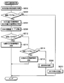
- FIG. 4 is a flowchart of the display control apparatus.
- FIG. 5 is a flowchart of the information acquisition process.
- FIG. 6 is a state transition diagram of the vehicle state
- FIG. 7 is a flowchart of the display position control process.
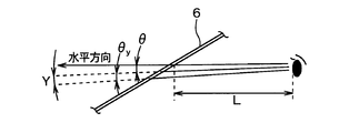
- FIG. 8 is a diagram for explaining the calculation of the moving amount of the video information.
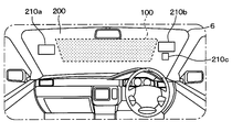
- FIG. 9 is a diagram for explaining the display prohibition area and the display permission area.
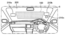
- FIG. 10 is a diagram for explaining the entire movement of the display prohibited area and the display permitted area.
- FIG. 11 is a flowchart of the individual correction process.
- FIG. 12 is a diagram for explaining the movement of individual video information.
- FIG. 13 is a diagram for explaining the movement of individual video information.
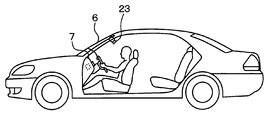
- FIG. 1 illustrates an overall configuration of a head-up display device according to an embodiment of the present disclosure.
- the head-up display device 1 according to this embodiment is mounted on a vehicle and includes an optical unit 2, a display control device 11, a vehicle state measurement unit 37, an indoor camera 23, and a line-of-sight detection unit 30.
- the optical unit 2 includes a plurality of, for example, three head-up displays 3 to 5, for example.
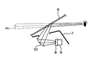
- the head-up displays 3 to 5 project individual images on the transparent front windshield 6 as shown in FIG.
- the front windshield 6 will be referred to as a wind glass 6.
- the head-up displays 3 to 5 display an image on the wind glass 6 is shown in FIG. That is, the head-up displays 3 to 5 are disposed in the instrument panel 7 of the vehicle shown in FIG. 2, and each includes a TFT liquid crystal panel 8, a backlight 9, and a mirror 10 as a display unit.
- the liquid crystal panel 8 acquires the video information from the display control device 11, receives the light from the backlight 9, and displays this video information as an image.
- the display light of the image output from the liquid crystal panel 8 is reflected by the mirror 10 and reflected toward the window glass 6, thereby forming a virtual image m in front of the window glass 6.
- the virtual image m is formed in front of the window glass 6, but for the viewer, it looks as if the image was displayed on the window glass 6. Is treated as a display screen projected on the window glass 6.
- each head-up display 3 to 5 is configured so that its orientation can be freely changed up, down, left, and right, and the position of the display screen displayed on the window glass 6 is changed by changing the orientation. It has been moved.
- the direction change of the liquid crystal panel 8 and the backlight 9 is automatically performed by the rotation mechanism 12.
- the rotating mechanism 12 supports the liquid crystal panel 8 and the backlight 9 so as to be rotatable about two orthogonal axes, and is centered on one axis and the other axis by two stepping motors 12a and 12b. It is a structure to rotate.
- a display control device 11 is connected to each head-up display 3-5.
- the display control device 11 is configured as a computer including a CPU, a RAM, a ROM, and an I / O lamp, and the CPU performs various processes according to a program stored in the ROM.
- a vehicle state measuring unit 37 is connected to the display control device 11.
- the vehicle state measurement unit 37 is connected to a vehicle state measurement sensor group 25.
- the vehicle state measurement sensor group 25 includes a three-axis gyro sensor 26, a steering wheel angle sensor 27, and a direction indicator 28.
- the 3-axis gyro sensor 26 outputs a signal corresponding to the posture of the vehicle, and outputs angular velocity information indicating angular velocities in the three-axis directions of the pitch direction, the roll direction, and the yaw direction.
- the steering wheel angle sensor 27 outputs steering angle information corresponding to the rotation angle of the steering wheel of the vehicle.
- the direction indicator 28 has a vehicle direction indicator lamp (blinker) and a direction indicator lever (both not shown), and blinks the vehicle direction indicator lamp in response to a user operation on the direction indicator lever.
- the direction indicator 28 outputs winker information indicating a right turn or a left turn according to a user operation on the direction indicator lever.
- the navigation device 13 is mounted on the vehicle.
- the navigation device 13 is configured as an audio video integrated type in which a DVD player 14 and a television receiver 15 are incorporated in addition to a radio receiver and a CD player (not shown). Further, the navigation device 13 incorporates a display unit 16 composed of a color liquid crystal display for projecting road maps, videos and television broadcast images.
- the navigation device 13 includes a position detection unit 17, a map data storage unit 18, an input unit 19 including a mechanical switch and a touch panel provided on the screen of the display unit 16, a control unit 20, and the like.
- the control unit 20 detects the current position from the position detection unit 17, acquires map information around the current position from the map data storage unit 18, and outputs road map video information (hereinafter simply referred to as map video information).
- the DVD player 14 acquires and outputs video information from the DVD, and the TV receiver 15 receives TV broadcast radio waves and outputs TV video information (hereinafter simply referred to as TV video information).
- map image information, video information, and television image information are given to the display control device 11 described above, and are displayed on the display unit 16 of the navigation device 13 under the control of the display control device 11.
- the map image information, video information, and TV image information are given to the optical unit 2 under the control of the display control device 11 and can be displayed on the window glass 6. Note that which of the map video information, the video information, and the television video information is displayed on the display unit 16 of the navigation device 13 is determined by operating the input unit 19 of the navigation device 13.
- an instrument video information generation device 21 is provided in the vehicle as a video information source given to the display control device 11.
- the instrument video information generating device 21 acquires measurement data from various instrument sensor groups 22 such as a vehicle speed sensor, a fuel remaining amount sensor, a hydraulic pressure sensor, and an engine rotation speed sensor, and generates instrument video information based on the measurement data.
- the display control device 11 gives the instrument video information to the optical unit 2 and displays it on the window glass 6.
- the head-up displays 3 to 5 of the optical unit 2 share the video to be displayed, the head-up display 3 is dedicated to map video information, the head-up display 4 is used for both video information and TV video information, The display 5 is dedicated to instrument video information.
- the display control device 11 changes the display position of the video information in a direction that does not hinder the driver's field of view according to the vehicle state, that is, a direction in which the driver's field of view is secured. ing.
- the vehicle in order to change the display position of the video information according to the vehicle state, the vehicle is provided with an indoor camera 23 as shown in FIG.
- the indoor camera 23 is arranged in the center of the front part of the ceiling of the vehicle interior, captures the driver's face, and outputs the captured image to the line-of-sight detection unit 30.
- the line-of-sight detection unit 30 detects both eyes from the driver's face photographed by the indoor camera 23, and detects the line of sight by performing image recognition processing (for example, pattern matching) on the images of both eyes.
- image recognition processing for example, pattern matching
- the captured image is subjected to image processing to detect the position (coordinates) of the driver's eyes.
- the line-of-sight detection method by the line-of-sight detection unit 30 includes, for example, a three-dimensional line-of-sight (for example, pattern matching) by performing image recognition processing (for example, pattern matching) on the direction of the driver's face and the bias direction of both eyes with respect to the face.
- a three-dimensional line-of-sight for example, pattern matching
- image recognition processing for example, pattern matching
- a method for detecting the line of sight there are a method of detecting eye movement, a method of using the boundary between the cornea and the sclera, a method of using a cornea reflection image, and a method of using a cornea reflection image and a pupil.
- An eye camera registered trademark
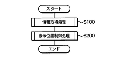
- an information acquisition process is performed (S100). A flowchart of this information acquisition process is shown in FIG.
- angular velocity information is acquired from the three-axis gyro sensor 26 (S102). Note that it is possible to specify how much the vehicle is traveling on a slope (uphill or downhill) with a road gradient by the angular velocity in the pitch direction included in the angular velocity information. Further, it is possible to specify whether the vehicle is traveling on a rough road such as a bumpy road by using the angular velocity in the roll direction and the angular velocity in the pitch direction included in the angular velocity information.
- steering angle information corresponding to the rotation angle of the steering wheel of the vehicle is obtained from the steering wheel steering angle sensor 27 (S104). Note that it is possible to periodically acquire the steering angle information and estimate the turning angle of the vehicle based on the amount of change in the previous steering wheel steering angle and the current steering wheel steering angle.
- the winker information output from the direction indicator 28 is acquired (S106). It is possible to specify whether the vehicle is turning right or left based on the winker information.
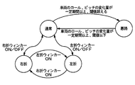
- FIG. 6 shows a state transition diagram of the vehicle state.
- the state transits to the “left turn” state.
- the winker information indicating the left turn is not acquired in the “left turn” state, the state returns to the “normal” state. .
- the state transits to the “right turn” state.
- the blinker information indicating the right turn is not acquired in the “right turn” state, the “normal” state is acquired.
- winker information indicating a right turn is acquired in a “left turn” state
- the state transits to a “right turn” state.
- winker information indicating a left turn is acquired in a “right turn” state
- a “left turn” state is acquired.
- the state transitions to the “bad road” state.
- a threshold value for example, 10 degrees
- the state transitions to the “normal” state.
- a bad road flag indicating “bad road” is stored in the RAM. Also, in the “right turn” state, a right turn flag indicating the right turn state is stored in the RAM, and in the “left turn” state, a left turn flag indicating the left turn state is stored in the RAM, and this processing is terminated.
- FIG. 7 shows a flowchart of the display position control process.
- a vehicle state specifying result is acquired (S202). Specifically, the result of the vehicle state specified in S108 is acquired.
- S203 it is determined whether there is a bad road flag (S203). Specifically, it is determined whether a bad road flag is stored in the RAM.
- FIG. 8 shows a state in which the driver is viewing specific video information determined in advance on the window glass 6.
- the distance L in the horizontal direction between the driver's eyes and the window glass 6 is specified using the position (coordinates) of the driver's eyes detected by the line-of-sight detection unit 30.
- the window glass 6 is divided into a display prohibition area that prohibits display of video information and a display permission area that allows display of video information, and displays video information in the display permission area. Yes.
- FIG. 9 shows a display example of video information when the vehicle is traveling on a flat road.
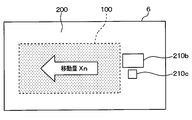
- a display prohibition area 100 is provided at the center, and a display permission area 200 is provided so as to surround the display prohibition area 100, and video information is displayed in the display permission area 200.
- display bodies 210a, 210b, and 210c are displayed.
- the entire display-prohibited area and the display-permitted area including the video information are moved in a direction in which the driver's view is secured. For example, when the vehicle is in an uphill running state, the entire display-prohibited area and the display-permitted area including video information are moved downward. In addition, when the vehicle is in a downhill running state, the entire display-prohibited area and the display-permitted area including video information are moved upward. In addition, when the vehicle is turning right, the entire display prohibited area and the entire display permitted area including the video information are moved to the right side, and when turning left, the entire display prohibited area and the entire display permitted area including the video information are displayed. Is moved to the left.
- the horizontal distance between the driver's eyes and the window glass 6 is L, and the direction in which the driver is viewing the video information (the direction of the line of sight).
- the angle ⁇ y can be obtained from the angular velocity of the triaxial gyro sensor 26 in the pitch direction. On the down slope, the angle ⁇ y may be a negative value.
- the display prohibition area 100 and the display permission area 200 are used using a table that defines the amount of movement of the steering angle information output from the steering angle sensor 27 and the entire video information in the horizontal direction.
- the overall movement amount X is determined. Note that the total movement amount X is determined so that the total movement amount of the display prohibition area 100 and the display permission area 200 increases as the rotation angle of the steering wheel of the vehicle increases. Further, here, only the determination of the total movement amount is performed, and the actual movement of the display of the video information is performed later.
- the determination in S212 is NO, and then it is determined whether there is a left turn flag (S214). Specifically, it is determined whether a left turn flag is stored in the RAM.
- FIG. 11 shows a flowchart of the individual correction process.
- this individual correction process first, it is determined whether or not the individual video information n existing in the moving direction can be displayed even if the entire image is moved (S302).
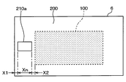
- a display body 210a having a horizontal length of Xn is displayed in the display permission area 200 on the left side of the display prohibition area 100, and a length X1 is displayed on the left side of the display body 210a. It is assumed that there is a margin and that there is a margin of length X2 on the right side of the display body 210a.
- the leftward movement amount X is the length of the left and right margins of the display body 210a ( X1 + X2) or less, it is determined that the individual video information n existing in the moving direction can be displayed even if the whole is moved, and the amount of movement X in the left direction is the left and right margins of the display body 210a. If it is larger than the length (X1 + X2), it is determined that display of the individual video information n existing in the moving direction is impossible when the whole is moved.
- the determination in S302 is NO, and next, the video information n that cannot be displayed is erased.
- the entire display prohibited area 100 and the display permitted area 200 are moved by the movement amount calculated in S206 (S306).
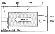
- the display body 210a on the left side of the display prohibition area 100 is deleted, and the display prohibition area 100 and the display permission area 200 including the individual video information n that can be displayed are displayed.
- the optical unit 2 is controlled to move to the left by the entire movement range specified in S204, and this process is terminated.
- the determination in S302 is YES, and then the individual video information n is the end. It is determined whether or not it is necessary to move (S304).
- the movement amount X in the left direction is the display body. If it is equal to or less than the margin length X1 on the end side (left side) 210a, it is determined that an area for displaying the video information is secured without moving the individual video information n to the end side, and leftward Is larger than the margin length X1 on the end side (left side) of the display body 210a, an area for displaying the video information is secured by moving the individual video information n to the end side. Is determined.
- the optical unit 2 is controlled to move the entire display-prohibited area 100 and the display-permitted area 200 by the movement amount calculated in S206, and this process ends.
- the determination in S304 is YES, and then the video information n is moved to the end. (S308).
- the display position of the display body 210a existing in the movement direction is corrected so as to move to the end of the display permission area 200, and the amount of movement calculated in S206 is displayed.
- the optical unit 2 is controlled so as to move the entire prohibited area 100 and display permitted area 200, and this process ends.
- the determination in S203 is YES, and display of all video information is prohibited (S210). Specifically, the optical unit 2 is controlled so as to prohibit display of all video information.
- the optical unit is configured to hide the video information included in the display permission area at the position overlapping the right half of the window glass 6 and display the image information included in the display permission area at the position overlapping the left half of the window glass 6 as it is. 2 is controlled and this processing is terminated.
- the optical unit is configured to hide the video information included in the display permission area at the position overlapping the left half of the window glass 6 and display the image information included in the display permission area at the position overlapping the right half of the window glass 6 as it is. 2 is controlled and this processing is terminated.
- the head-up display device 1 projects the image light toward the window glass 6 of the vehicle and displays the image information reflected on the window glass 6 as a virtual image, and the window glass 6.
- a display control device 11 for controlling the optical unit 2 so as to display the video information and the display control device 11 sets the position of the video information in a direction in which the field of view of the driver of the vehicle is secured according to the vehicle state. Since the optical unit 2 is controlled to move, the video information can be displayed at a display position suitable for the vehicle state.
- the display control device 11 moves the display position of the video information downward when the vehicle is identified as being in an uphill running state, and the upward direction when the vehicle is identified as being in a downhill running state.
- the display position of the video information can be moved.
- the display control device 11 moves the display position of the video information to the right when the vehicle is specified as turning right, and the left when the vehicle is specified as turning left.
- the display position of the video information can be moved.
- the display control device 11 can display the video information in the display permission area 200 that permits the display of the video information defined on the window glass 6.
- the display control device 11 specifies the total movement amount for moving the entire display permission area including the video information, and optically moves the entire display permission area including the video information by the specified total movement amount.
- the unit can be controlled.
- the display control apparatus 11 moves the entire display permission area including the video information by the specified total movement amount, whether or not an area for displaying the video information is secured in the display permission area in the movement direction. If it is determined that the display area for displaying the video information is not secured in the display permission area in the moving direction, the optical unit is controlled so as to hide the video information for which the display area is not secured. In particular, it is possible to secure the field of view of the driver of the vehicle even when the total movement amount becomes large.
- the display control device 11 individually sets the display position of the video information in the movement direction on the end side of the display permission area.
- An area for determining whether or not an area for displaying video information without being moved is secured, and displaying the video information without individually moving the display position of the video information in the moving direction to the end side of the display permission area.
- the display position of the display information area including the video information is moved as a whole without individually moving the display position of the video information in the moving direction to a position where the display is possible. Since the optical unit is controlled, the position of the display permission area including the video information can be moved as a whole without individually moving the display position of the video information in the moving direction to a position where it can be displayed.
- the display control device 11 can be controlled so as to move the position of the display permission area including the video information as a whole while individually moving the display position of the video information to the end of the display permission area.
- the display control device 11 specifies whether the vehicle turns right or left based on a signal corresponding to the operation of the direction indicator lever for controlling the direction indicator lamp of the vehicle, and when the vehicle is specified to turn right If the optical unit is controlled to hide the video information in the right half area of the front windshield and the vehicle is specified to turn left, the video information in the left half area of the front windshield is hidden. Since the optical unit is controlled as described above, it is possible to secure the field of view of the driver of the vehicle when the vehicle turns right or left.
- the display control device 11 specifies whether or not the vehicle is traveling on a rough road with a large change in posture based on information for determining whether or not the vehicle is traveling on a rough road with a large variation in posture.
- the optical unit is controlled so as to prohibit the display of all video information. Can be secured.
- the entire display prohibited area and the display permitted area are moved in accordance with the vehicle state so that the driver's field of view is ensured.
- the display prohibited area is not defined.
- the display permission area including the video information may be moved.
- the steering angle information output from the steering wheel steering angle sensor 27 is periodically acquired, and the turning amount of the vehicle is estimated based on the previous steering wheel steering angle and the change amount of the current steering wheel steering angle.
- the amount of movement of the video information in the left-right direction is specified from the turning amount of the vehicle.
- the turning amount of the vehicle is estimated based on the angular velocity information input from the gyro sensor, and the turning amount of the vehicle is calculated.
- the amount of movement of the video information in the left-right direction may be specified.
- a transition to a “bad road” state is made using a condition other than the above conditions, such as a transition to a “bad road” state based on an output signal of an acceleration sensor that detects vehicle acceleration. You may do it.
- S108 corresponds to a vehicle state identification device
- S206 corresponds to an overall movement amount identification device
- S302 corresponds to an area securing determination device
- S304 corresponds to an individual movement determination device.
Landscapes
- Engineering & Computer Science (AREA)
- Physics & Mathematics (AREA)
- General Physics & Mathematics (AREA)
- Chemical & Material Sciences (AREA)
- Mechanical Engineering (AREA)
- Transportation (AREA)
- Combustion & Propulsion (AREA)
- Theoretical Computer Science (AREA)
- Optics & Photonics (AREA)
- Computer Hardware Design (AREA)
- Computer Graphics (AREA)
- Software Systems (AREA)
- General Engineering & Computer Science (AREA)
- Multimedia (AREA)
- Architecture (AREA)
- Signal Processing (AREA)
- Instrument Panels (AREA)
- Fittings On The Vehicle Exterior For Carrying Loads, And Devices For Holding Or Mounting Articles (AREA)
Abstract
ヘッドアップディスプレイ装置は、車両のフロントウインドシールド(6)に向けて映像光を投射し、該フロントウインドシールドに反射した映像情報を虚像として表示する光学ユニット(2)と、前記フロントウインドシールドに前記映像情報を表示するように前記光学ユニットを制御する表示制御装置(11)と、車両状態を特定する車両状態特定装置(S108)と、を備える。前記表示制御装置は、前記車両状態特定装置により特定された前記車両状態に従って前記車両の運転者の視界が確保される方向に、前記映像情報の表示位置を移動させるように前記光学ユニットを制御する。
Description
本開示は、2014年4月16日に出願された日本出願番号2014-84701号に基づくもので、ここにその記載内容を援用する。
本開示は、ヘッドアップディスプレイ装置に関するものである。
この種の装置は、運転者の視線と指さし方向を検出するとともに、視線と指さし方向の一致を検出するようにし、運転者が視線と指さし方向を移動させたい表示画面に移動させると、視線と指さし方向が一致した表示画面が移動対象画面として選択され、運転者が視線と指さし方向を所望の位置まで移動させると、移動対象画面が視線と指さし方向が不一致となる位置まで移動するように構成された(例えば、特許文献1参照)。
ところで、車両を運転する際には、車両状態に応じて運転者が自然に視線を移動せざるを得ない状況が生じる。例えば、上り坂では視線を下方向に移動させ、下り坂では視線を上方向に移動させ、右旋回時には視線を右に移動させ、左旋回時には視線を左に移動させる必要が生じる。
しかしながら、上記特許文献1に記載された装置は、移動させたい表示画面を乗員の好みの位置に移動させることは可能であるが、車両状態に応じて運転者が自然に視線を移動せざるを得ない状況であっても表示画面の表示位置は固定されるため、映像情報により前方視界が妨げられてしまう場合があるという問題があった。
本開示は、車両状態に適した表示位置に映像情報を表示できるようにすることを目的とする。
上記目的を達成するため、本開示の第一の態様においては、車両のフロントウインドシールドに向けて映像光を投射し、該フロントウインドシールドに反射した映像情報を虚像として表示する光学ユニットと、フロントウインドシールドに映像情報を表示するように光学ユニットを制御する表示制御装置と、車両状態を特定する車両状態特定装置と、を備える。前記表示制御装置は、前記車両状態特定装置により特定された車両状態に従って前記車両の運転者の視界が確保される方向に、映像情報の表示位置を移動させるように前記光学ユニットを制御する。
このような構成によれば、表示制御装置は、車両状態に従って車両の運転者の視界が確保される方向に、映像情報の表示位置を移動させるように光学ユニットを制御するので、車両状態に適した表示位置に映像情報を表示することができる。
本開示の一実施形態に係るヘッドアップディスプレイ装置の全体構成を図1に示す。本実施形態のヘッドアップディスプレイ装置1は、車両に搭載されており、光学ユニット2、表示制御装置11、車両状態測定部37、室内カメラ23および視線検出部30を備えている。光学ユニット2は、複数台、例えば3台のヘッドアップディスプレイ3~5を備えている。ヘッドアップディスプレイ3~5は、図2に示すように、透明なフロントウインドシールド6に個別の画像を映し出す。なお、以下では、フロントウインドシールド6をウインドガラス6と称することとする。
ヘッドアップディスプレイ3~5がウインドガラス6に画像を映し出す原理は、図3に示されている。即ち、ヘッドアップディスプレイ3~5は、図2に示す車両のインストルメントパネル7内に配設されており、それぞれ表示部としてのTFT型液晶パネル8、バックライト9およびミラー10を備えている。液晶パネル8は、表示制御装置11から映像情報を取得し、バックライト9からの光を受けてこの映像情報を画像として表示する。この液晶パネル8から出力される画像の表示光は、ミラー10に反射されてウインドガラス6に向けて反射され、これにより、ウインドガラス6の前方に虚像mとして結像される。この場合、虚像mは、ウインドガラス6の前方に結像されるが、見る人にとっては、あたかも画像がウインドガラス6に映し出されたように見えるので、以下では、虚像mとして結像される画像をウインドガラス6に映し出された表示画面として扱うこととする。
本実施形態では、各ヘッドアップディスプレイ3~5は、その向きを上下左右に自在に変えることができるように構成されており、その向きの変換によって、ウインドガラス6に映し出される表示画面の位置が移動されるようになっている。液晶パネル8およびバックライト9の向きの変換は、回動機構12によって自動的に行われる。この回動機構12は、液晶パネル8およびバックライト9を直交する2軸を中心にして回動できるように支持し、2個のステッピングモータ12a、12bによって一方の軸および他方の軸を中心に回動させる構成のものである。
また、各ヘッドアップディスプレイ3~5には、表示制御装置11が接続されている。この表示制御装置11は、CPU、RAM、ROM、I/O灯を備えたコンピュータとして構成されており、CPUはROMに記憶されたプログラムに従って各種処理を実施する。
また、表示制御装置11には、車両状態測定部37が接続されている。また、この車両状態測定部37には、車両状態測定用センサ群25が接続されている。車両状態測定用センサ群25は、3軸ジャイロセンサ26、ハンドル操舵角センサ27および方向指示器28を備える。
3軸ジャイロセンサ26は、車両の姿勢に応じた信号を出力するものであり、ピッチ方向、ロール方向、ヨー方向の3軸方向の角速度を示す角速度情報を出力する。
ハンドル操舵角センサ27は、車両のステアリングホイールの回転角度に応じた操舵角情報を出力する。
方向指示器28は、車両の方向指示灯(ウィンカー)と方向指示レバー(いずれも図示せず)を有しており、ユーザの方向指示レバーに対する操作に応じて車両の方向指示灯を点滅させる。方向指示器28は、ユーザの方向指示レバーに対する操作に応じて右折または左折を示すウィンカー情報を出力する。
一方、車両には、ナビゲーション装置13が搭載されている。このナビゲーション装置13は、図示しないラジオ受信機やCDプレーヤの他、DVDプレーヤ14、テレビ受信機15を組み込んだオーディオビデオ一体型として構成されている。また、ナビゲーション装置13には、道路地図、ビデオやテレビ放送の映像を映し出すためのカラー液晶ディスプレイからなる表示部16が組み込まれている。
ナビゲーション装置13は、位置検出部17、地図データ記憶部18、メカニカルスイッチや表示部16の画面上に設けられたタッチパネルなどからなる入力部19、制御部20などを備えている。制御部20は、位置検出部17から現在位置を検出し、地図データ記憶部18から現在位置周辺の地図情報を取得して道路地図の映像情報(以下、単に地図映像情報)を出力する。また、DVDプレーヤ14は、DVDからビデオ情報を取得して出力し、テレビ受信機15は、テレビ放送電波を受信してテレビの映像情報(以下、単にテレビ映像情報)を出力する。
これらの地図映像情報、ビデオ情報、テレビ映像情報は、前述の表示制御装置11に与えられ、この表示制御装置11の制御下において、ナビゲーション装置13の表示部16に表示される。また、それら地図映像情報、ビデオ情報、テレビ映像情報は、表示制御装置11の制御下において、光学ユニット2に与えられ、ウインドガラス6に表示することもできるようになっている。なお、ナビゲーション装置13の表示部16に、地図映像情報、ビデオ情報、テレビ映像情報のうちいずれを表示するかは、ナビゲーション装置13の入力部19の操作によって行う。
車両には、表示制御装置11に与えられる映像情報源として、上記のナビゲーション装置13、DVDプレーヤ14、テレビ受信機15の他に、計器用映像情報生成装置21が設けられている。この計器用映像情報生成装置21は、車速センサ、燃料残量センサ、油圧センサ、エンジン回転速度センサなどの各種計器用センサ群22から計測データを取得し、これを基に計器映像情報を生成して表示制御装置11に送る。表示制御装置11は、この計器映像情報を光学ユニット2に与え、ウインドガラス6に表示させるようになっている。
ここで、光学ユニット2のヘッドアップディスプレイ3~5は、それぞれ表示する映像を分担しており、ヘッドアップディスプレイ3は地図映像情報専用、ヘッドアップディスプレイ4はビデオ情報およびテレビ映像情報兼用、ヘッドアップディスプレイ5は計器映像情報専用となっている。
本実施形態における表示制御装置11は、車両状態に応じて車両の運転者の視界の妨げとならない方向、すなわち、運転者の視界が確保される方向に映像情報の表示位置を変化させるようになっている。
このように、車両状態に応じて映像情報の表示位置を変化させるため、図2に示すように、車両には、室内カメラ23が設けられている。この室内カメラ23は、車室内の天井の前部中央に配置され、運転者の顔を撮影し、撮影した画像を視線検出部30へ出力する。
視線検出部30は、室内カメラ23により撮影された運転者の顔から両目を検出し、その両目の画像を画像認識処理(例えば、パターンマッチング)することにより視線を検出するとともに、室内カメラ23により撮影された画像に画像処理を施して運転者の目の位置(座標)を検出する。
視線検出部30による視線検出方法は、例えば、運転者の顔の向きおよび顔面に対する両目の黒目の偏り方向とその度合いを画像認識処理(例えば、パターンマッチング)することにより、3次元での視線(方向)を判断するようにしている。
視線の検出方法としては、眼球運動を検出する方法、角膜と強膜の境界を利用する方法、角膜反射像を利用する方法、角膜反射像と瞳孔とを利用する方法などがある。また、アイカメラ(登録商標)を使用してもよい。
次に、図4~図14を参照して、本ヘッドアップディスプレイ装置1における表示制御装置11の処理について説明する。車両のイグニッションスイッチがオン状態になると、本ヘッドアップディスプレイ装置1およびナビゲーション装置13は動作状態となり、表示制御装置11は、図4に示す処理を定期的(例えば、1秒毎)に実施する。
まず、情報取得処理を実施する(S100)。この情報取得処理のフローチャートを図5に示す。この情報取得処理では、まず、3軸ジャイロセンサ26より角速度情報を取得する(S102)。なお、角速度情報に含まれるピッチ方向の角速度により、車両がどの程度の道路勾配の坂道(上り坂または下り坂)を走行中であるかを特定することが可能である。また、角速度情報に含まれるロール方向の角速度およびピッチ方向の角速度を用いて凸凹道のような悪路を走行中であるかを特定することが可能である。
次に、ハンドル操舵角センサ27より車両のステアリングホイールの回転角度に応じた操舵角情報を取得する(S104)。なお、操舵角情報を定期的に取得して、前回のハンドル操舵角と今回のハンドル操舵角の変化量に基づいて車両の旋回角を推定することが可能である。
次に、方向指示器28より出力されるウィンカー情報を取得する(S106)。このウィンカー情報に基づいて車両が右折中または左折中であるか否かを特定することが可能である。
次に、車両状態を特定する(S108)。本実施形態では、「通常」、「悪路」、「右折」、「左折」の4つの状況の状態を特定する。図6に、車両状態の状態遷移図を示す。
「通常」の状態で、左折を示すウィンカー情報が取得されると「左折」の状態に遷移し、「左折」の状態で、左折を示すウィンカー情報が取得されなくなると「通常」の状態に戻る。
また、「通常」の状態で、右折を示すウィンカー情報が取得されると「右折」の状態に遷移し、「右折」の状態で、右折を示すウィンカー情報が取得されなくなると「通常」の状態に戻る。
また、「左折」の状態で、右折を示すウィンカー情報が取得されると「右折」の状態に遷移し、「右折」の状態で、左折を示すウィンカー情報が取得されると「左折」の状態に戻る。
また、「通常」の状態で、ロール角とピッチ角の少なくとも一方の変化量が一定期間(例えば、1秒)以上、閾値(例えば、10度)を超えると、「悪路」の状態に遷移し、「悪路」の状態で、ロール角とピッチ角の少なくとも一方の変化量が一定期間(例えば、1秒)以上、閾値(例えば、10度)以下になると、「通常」の状態に遷移する。
ここで、「悪路」の状態では、「悪路」であることを示す悪路フラグをRAMに記憶させる。また、「右折」の状態では、右折の状態を示す右折フラグをRAMに記憶させ、「左折」の状態では、左折の状態を示す左折フラグをRAMに記憶させ、本処理を終了する。
図4の説明に戻り、情報取得処理S100が終了すると、次に、表示位置制御処理を実施する(S200)。図7に、この表示位置制御処理のフローチャートを示す。
この表示位置制御処理では、まず、車両状態の特定結果を取得する(S202)。具体的には、S108で特定した車両状態の結果を取得する。
次に、悪路フラグがあるか否かを判定する(S203)。具体的には、RAMに悪路フラグが記憶されているか否かを判定する。
ここで、RAMに悪路フラグが記憶されていない場合、S203の判定はNOとなり、次に、運転者の目の位置と特定の映像情報の表示位置の位置関係を特定する(S204)。図8に、運転者がウインドガラス6上の予め定められた特定の映像情報を見ている様子を示す。ここでは、視線検出部30により検出された運転者の目の位置(座標)を用いて、運転者の目とウインドガラス6の水平方向の距離Lを特定する。
次に、全体の移動量X、Yを特定する(S206)。本実施形態においては、ウインドガラス6が、映像情報の表示を禁止する表示禁止領域と映像情報の表示を許可する表示許可領域とに区画され、表示許可領域に映像情報を表示するようになっている。
図9に、車両が平坦な道路を走行している場合の映像情報の表示例を示す。図に示すように、中央に表示禁止領域100が設けられ、この表示禁止領域100を囲むように表示許可領域200が設けられており、この表示許可領域200に映像情報を表示するようになっている。なお、表示許可領域200には、表示体210a、210b、210cが表示されている。
そして、車両の姿勢が変化すると、運転者の視界が確保される方向に、表示禁止領域と、映像情報を含む表示許可領域の全体を移動させるようになっている。例えば、車両の状態が、上り坂走行時の状態では、表示禁止領域と、映像情報を含む表示許可領域の全体を下方向に移動させる。また、車両の状態が、下り坂走行時の状態では、表示禁止領域と、映像情報を含む表示許可領域の全体を上方向に移動させるようになっている。また、車両の状態が、右旋回時には、表示禁止領域と、映像情報を含む表示許可領域の全体を右側に移動させ、左旋回時には、表示禁止領域と、映像情報を含む表示許可領域の全体を左側に移動させるようになっている。
例えば、車両が上り坂にさしかかると、図10に示すように、運転者の視界が確保されるように、表示禁止領域100と表示許可領域200の全体を下方に移動させるように全体の移動量Yを算出する。
ここで、角度θyの上り勾配では、図8に示したように、運転者の目とウインドガラス6の水平方向の距離をLとし、運転者が映像情報を見ている方向(視線の方向)と水平方向のなす角をθとすると、映像情報の下方向への移動量Yは、Y=L*(tan(θ+θy))-tanθとして算出することができる。なお、角度θyは、3軸ジャイロセンサ26のピッチ方向の角速度により求めることができる。また、下り勾配では、角度θyを負の値とすればよい。
また、右旋回時および左旋回時には、ハンドル操舵角センサ27より出力される操舵角情報と映像情報の全体の左右方向の移動量を規定したテーブルを用いて表示禁止領域100と表示許可領域200の全体の移動量Xを決定する。なお、車両のステアリングホイールの回転角度が大きいほど表示禁止領域100と表示許可領域200の全体の移動量が大きくなるように全体の移動量Xを決定する。また、ここでは、全体の移動量の決定を行うだけで、実際の映像情報の表示の移動は後で実施する。
次に、右折フラグがあるか否かを判定する(S212)。具体的には、RAMに右折フラグが記憶されているか否かを判定する。
ここで、RAMに右折フラグが記憶されていない場合、S212の判定はNOとなり、次に、左折フラグがあるか否かを判定する(S214)。具体的には、RAMに左折フラグが記憶されているか否かを判定する。
ここで、RAMに左折フラグが記憶されていない場合、S214の判定はNOとなり、次に、個別に映像情報の表示位置を補正する個別補正処理を実施する(S300)。
図11に、この個別補正処理のフローチャートを示す。この個別補正処理では、まず、全体を移動させても移動方向に存在する個別の映像情報nの表示が可能か否かを判定する(S302)。
ここで、図12に示すように、表示禁止領域100の左側の表示許可領域200に、水平方向の長さがXnの表示体210aが表示されており、表示体210aの左側に長さX1の余白があり、表示体210aの右側に長さX2の余白があるものとする。
ここで、表示禁止領域100と表示許可領域200の全体を移動量Xだけ左方向へ移動させることとなった場合、左方向への移動量Xが、表示体210aの左右の余白の長さ(X1+X2)以下であれば、全体を移動させても移動方向に存在する個別の映像情報nの表示が可能であると判定し、左方向への移動量Xが、表示体210aの左右の余白の長さ(X1+X2)よりも大きければ、全体を移動させると移動方向に存在する個別の映像情報nの表示が不可能であると判定する。
ここで、例えば、左方向への移動量Xが、表示体210aの左右の余白の長さ(X1+X2)よりも大きい場合、S302の判定はNOとなり、次に、表示できない映像情報nを消去して、S206にて算出した移動量分、表示禁止領域100と表示許可領域200の全体を移動させる(S306)。
具体的には、図13に示すように、表示禁止領域100の左側にあった表示体210aを消去して、表示禁止領域100と、表示可能な個別の映像情報nを含む表示許可領域200の全体をS204にて特定した全体の移動領分だけ左方向へ移動させるよう光学ユニット2を制御し、本処理を終了する。
また、例えば、左方向への移動量Xが、表示体210aの左右の余白の長さ(X1+X2)以下となった場合、S302の判定はYESとなり、次に、個別の映像情報nを端に移動させる必要があるか否かを判定する(S304)。
ここで、図12に示した表示例において、表示禁止領域100と表示許可領域200の全体を移動量Xだけ左方向へ移動させることとなった場合、左方向への移動量Xが、表示体210aの端部側(左側)の余白の長さX1以下であれば、個別の映像情報nを端部側に移動させることなく映像情報を表示させる領域が確保されると判定し、左方向への移動量Xが、表示体210aの端部側(左側)の余白の長さX1より大きければ、個別の映像情報nを端部側に移動させることにより映像情報を表示させる領域が確保されると判定する。
ここで、例えば、左方向への移動量Xが、表示体210aの端部側(左側)の余白の長さX1以下となった場合、S304の判定はNOとなり、次に、全体の移動量X、Yにしたがって全体を移動させる(S310)。具体的には、S206にて算出した移動量分、表示禁止領域100と表示許可領域200の全体を移動させるよう光学ユニット2を制御し、本処理を終了する。
また、例えば、左方向への移動量Xが、表示体210aの端部側(左側)の余白の長さX1より大きい場合、S304の判定はYESとなり、次に、映像情報nを端に移動させるよう補正する(S308)。
具体的には、図14に示すように、移動方向に存在する表示体210aの表示位置を表示許可領域200の端部まで移動させるように補正するとともに、S206にて算出した移動量分、表示禁止領域100と表示許可領域200の全体を移動させるように光学ユニット2を制御し、本処理を終了する。
図7の説明に戻り、車両が悪路を走行しており、RAMに悪路フラグが記憶されている場合は、S203の判定はYESとなり、映像情報の表示を全て禁止する(S210)。具体的には、映像情報の表示を全て禁止するよう光学ユニット2を制御する。
また、RAMに右折フラグが記憶されている場合は、S212の判定はYESとなり、次に、右半分の映像情報を消去する(S216)。すなわち、ウインドガラス6の右側半分と重なる位置の表示許可領域に含まれる映像情報を非表示とし、ウインドガラス6の左側半分と重なる位置の表示許可領域に含まれる映像情報はそのまま表示するよう光学ユニット2を制御し、本処理を終了する。
また、RAMに左折フラグが記憶されている場合は、S214の判定はYESとなり、次に、左半分の映像情報を消去する(S218)。すなわち、ウインドガラス6の左側半分と重なる位置の表示許可領域に含まれる映像情報を非表示とし、ウインドガラス6の右側半分と重なる位置の表示許可領域に含まれる映像情報はそのまま表示するよう光学ユニット2を制御し、本処理を終了する。
上記した構成によれば、ヘッドアップディスプレイ装置1は、車両のウインドガラス6に向けて映像光を投射し、該ウインドガラス6に反射した映像情報を虚像として表示する光学ユニット2と、ウインドガラス6に映像情報を表示するように光学ユニット2を制御する表示制御装置11と、を備え、表示制御装置11は、車両状態に従って車両の運転者の視界が確保される方向に、映像情報の位置を移動させるように光学ユニット2を制御するので、車両状態に適した表示位置に映像情報を表示することができる。
また、表示制御装置11は、車両が上り坂走行時の状態と特定された場合、下方向に映像情報の表示位置を移動させ、車両が下り坂走行時の状態と特定された場合、上方向に映像情報の表示位置を移動させることができる。
また、表示制御装置11は、車両が右旋回している状態と特定された場合、右方向に映像情報の表示位置を移動させ、車両が左旋回している状態と特定された場合、左方向に映像情報の表示位置を移動させることができる。
また、表示制御装置11は、ウインドガラス6に規定された映像情報の表示を許可する表示許可領域200に映像情報を表示することができる。
また、表示制御装置11は、映像情報を含む表示許可領域の全体を移動させる全体移動量を特定し、特定された全体移動量だけ、映像情報を含む表示許可領域の全体を移動させるように光学ユニットを制御することができる。
また、表示制御装置11は、特定された全体移動量だけ映像情報を含む表示許可領域の全体を移動させたときに、移動方向の表示許可領域に映像情報を表示する領域が確保されるか否かを判定し、移動方向の表示許可領域に映像情報を表示する表示領域が確保されないと判定された場合、該表示領域が確保されない映像情報を非表示とするように光学ユニットを制御するので、特に、全体移動量が大きくなった場合でも、車両の運転者の視界を確保することが可能である。
また、表示制御装置11は、移動方向の表示許可領域に映像情報を表示する領域が確保されると判定された場合、移動方向の映像情報の表示位置を表示許可領域の端部側に個別に移動させることなく映像情報を表示する領域が確保されるか否かを判定し、移動方向の映像情報の表示位置を表示許可領域の端部側に個別に移動させることなく映像情報を表示する領域が確保されると判定された場合、該移動方向の映像情報の表示位置を表示可能となる位置に個別に移動させることなく、映像情報を含む表示許可領域の位置を全体的に移動させるように光学ユニットを制御するので、移動方向の映像情報の表示位置を表示可能となる位置に個別に移動させることなく、映像情報を含む表示許可領域の位置を全体的に移動させることができる。
また、表示制御装置11は、移動方向の映像情報の表示位置を表示許可領域の端部側に個別に移動させることにより映像情報を表示する領域が確保されると判定された場合、該移動方向の映像情報の表示位置を表示許可領域の端部側に個別に移動させつつ、映像情報を含む表示許可領域の位置を全体的に移動させるように光学ユニットを制御することができる。
また、表示制御装置11は、車両の方向指示灯を制御するための方向指示レバーの操作に応じた信号に基づいて車両が右折するか左折するかを特定し、車両が右折すると特定された場合、フロントウインドシールドの右側半分の領域の映像情報を非表示とするように光学ユニットを制御し、車両が左折すると特定された場合、フロントウインドシールドの左側半分の領域の映像情報を非表示とするように光学ユニットを制御するので、車両が右左折する際の車両の運転者の視界を確保することができる。
また、表示制御装置11は、車両が姿勢の変動の大きな悪路を走行中か否かを判定するための情報に基づいて車両が姿勢の変動の大きな悪路を走行中か否かを特定し、車両が悪路を走行中であると特定された場合、全ての映像情報の表示を禁止するように光学ユニットを制御するので、車両が悪路を走行する際の車両の運転者の視界を確保することができる。
なお、本開示は上述の実施形態に限定されることなく、本開示の趣旨を逸脱しない範囲内で、以下のように種々変形可能である。
例えば、上記実施形態では、運転者の視界が確保されるように、車両状態に応じて表示禁止領域と表示許可領域の全体を移動させるようにしたが、例えば、表示禁止領域を規定することなく、映像情報を含む表示許可領域を移動させるようにしてもよい。
また、上記実施形態では、ハンドル操舵角センサ27より出力される操舵角情報を定期的に取得し、前回のハンドル操舵角と今回のハンドル操舵角の変化量に基づいて車両の旋回量を推定し、この車両の旋回量から映像情報の左右方向の移動量を特定するようにしたが、例えば、ジャイロセンサより入力される角速度情報に基づいて車両の旋回量を推定し、この車両の旋回量から映像情報の左右方向の移動量を特定するようにしてもよい。
また、上記実施形態では、ロール角とピッチ角の少なくとも一方の変化量が一定期間(例えば、1秒)以上、閾値(例えば、10度)を超えると、「悪路」の状態に遷移する例を示したが、例えば、車両の加速度を検出する加速度センサの出力信号に基づいて「悪路」の状態に遷移するなど、上記した条件以外の条件を用いて「悪路」の状態に遷移するようにしてもよい。
なお、S108が車両状態特定装置に相当し、S206が全体移動量特定装置に相当し、S302が領域確保判定装置に相当し、S304が個別移動判定装置に相当する。
本開示は、実施例に準拠して記述されたが、本開示は当該実施例や構造に限定されるものではないと理解される。本開示は、様々な変形例や均等範囲内の変形をも包含する。加えて、様々な組み合わせや形態、さらには、それらに一要素のみ、それ以上、あるいはそれ以下、を含む他の組み合わせや形態をも、本開示の範疇や思想範囲に入るものである。
Claims (12)
- 車両のフロントウインドシールド(6)に向けて映像光を投射し、該フロントウインドシールドに反射した映像情報を虚像として表示する光学ユニット(2)と、
前記フロントウインドシールドに前記映像情報を表示するように前記光学ユニットを制御する表示制御装置(11)と、
車両状態を特定する車両状態特定装置(S108)と、を備え、
前記表示制御装置は、前記車両状態特定装置により特定された前記車両状態に従って前記車両の運転者の視界が確保される方向に、前記映像情報の表示位置を移動させるように前記光学ユニットを制御するヘッドアップディスプレイ装置。 - 前記表示制御装置は、前記車両状態特定装置により前記車両が上り坂走行時の状態と特定された場合、下方向に前記映像情報の表示位置を移動させる請求項1に記載のヘッドアップディスプレイ装置。
- 前記表示制御装置は、前記車両状態特定装置により前記車両が下り坂走行時の状態と特定された場合、上方向に前記映像情報の表示位置を移動させる請求項1または2に記載のヘッドアップディスプレイ装置。
- 前記表示制御装置は、前記車両状態特定装置により前記車両が右旋回している状態と特定された場合、右方向に前記映像情報の表示位置を移動させる請求項1ないし3のいずれか1つに記載のヘッドアップディスプレイ装置。
- 前記表示制御装置は、前記車両状態特定装置により前記車両が左旋回している状態と特定された場合、左方向に前記映像情報の表示位置を移動させる請求項1ないし4のいずれか1つに記載のヘッドアップディスプレイ装置。
- 前記表示制御装置は、前記フロントウインドシールドに規定された前記映像情報の表示を許可する表示許可領域(200)に前記映像情報を表示するようになっている請求項1ないし5のいずれか1つに記載のヘッドアップディスプレイ装置。
- 前記表示制御装置は、前記映像情報を含む前記表示許可領域の全体を移動させる全体移動量を特定する全体移動量特定装置(S206)を備え、
該全体移動量算出装置により特定された全体移動量だけ、前記映像情報を含む前記表示許可領域の全体を移動させるように前記光学ユニットを制御する請求項6に記載のヘッドアップディスプレイ装置。 - 前記表示制御装置は、前記全体移動量特定装置により特定された全体移動量だけ前記映像情報を含む前記表示許可領域の全体を移動させたときに、移動方向の前記表示許可領域に前記映像情報を表示する領域が確保されるか否かを判定する領域確保判定装置(S302)を備え、
前記領域確保判定装置により前記移動方向の前記表示許可領域に前記映像情報を表示する表示領域が確保されないと判定された場合、該表示領域が確保されない前記映像情報を非表示とするように前記光学ユニットを制御する請求項6に記載のヘッドアップディスプレイ装置。 - 前記映像情報は、複数の映像情報アイテムを含み、
前記表示制御装置は、前記領域確保判定装置により前記移動方向の前記表示許可領域に前記映像情報を表示する領域が確保されると判定された場合、前記移動方向の前記複数の映像情報アイテムの表示位置を前記表示許可領域の端部側に個別に移動させることなく前記映像情報を表示する領域が確保されるか否かを判定する個別移動判定装置(S304)を備え、
前記個別移動判定装置により前記移動方向の前記複数の映像情報アイテムの表示位置を前記表示許可領域の端部側に個別に移動させることなく前記映像情報を表示する領域が確保されると判定された場合、該移動方向の前記複数の映像情報アイテムの表示位置を表示可能となる位置に個別に移動させることなく、前記映像情報を含む前記表示許可領域の位置を全体的に移動させるように前記光学ユニットを制御する請求項6に記載のヘッドアップディスプレイ装置。 - 前記映像情報は、複数の映像情報アイテムを含み、
前記表示制御装置は、前記個別移動判定装置により前記移動方向の前記複数の映像情報アイテムの表示位置を前記表示許可領域の端部側に個別に移動させることにより前記映像情報を表示する領域が確保されると判定された場合、該移動方向の前記複数の映像情報アイテムの表示位置を前記表示許可領域の端部側に個別に移動させつつ、前記映像情報を含む前記表示許可領域の位置を全体的に移動させるように前記光学ユニットを制御する請求項8に記載のヘッドアップディスプレイ装置。 - 前記車両状態特定装置は、前記車両の方向指示灯を制御するための方向指示レバーの操作に応じた信号に基づいて前記車両が右折するか左折するかを特定し、
前記表示制御装置は、前記車両状態特定装置により前記車両が右折すると特定された場合、前記フロントウインドシールドの右側半分の領域の前記映像情報を非表示とするように前記光学ユニットを制御し、
前記車両状態特定装置により前記車両が左折すると特定された場合、前記フロントウインドシールドの左側半分の領域の前記映像情報を非表示とするように前記光学ユニットを制御する請求項1ないし10のいずれか1つに記載のヘッドアップディスプレイ装置。 - 前記車両状態特定装置は、前記車両が姿勢の変動の大きな悪路を走行中か否かを判定するための情報に基づいて前記車両が姿勢の変動の大きな悪路を走行中か否かを特定し、
前記表示制御装置は、前記車両状態特定装置により前記悪路を走行中であると特定された場合、全ての前記映像情報の表示を禁止するように前記光学ユニットを制御する請求項1ないし11のいずれか1つに記載のヘッドアップディスプレイ装置。
Priority Applications (1)
| Application Number | Priority Date | Filing Date | Title |
|---|---|---|---|
| US15/303,307 US9817237B2 (en) | 2014-04-16 | 2015-04-06 | Head-up display device |
Applications Claiming Priority (2)
| Application Number | Priority Date | Filing Date | Title |
|---|---|---|---|
| JP2014-084701 | 2014-04-16 | ||
| JP2014084701A JP6369106B2 (ja) | 2014-04-16 | 2014-04-16 | ヘッドアップディスプレイ装置 |
Publications (1)
| Publication Number | Publication Date |
|---|---|
| WO2015159500A1 true WO2015159500A1 (ja) | 2015-10-22 |
Family
ID=54323726
Family Applications (1)
| Application Number | Title | Priority Date | Filing Date |
|---|---|---|---|
| PCT/JP2015/001918 WO2015159500A1 (ja) | 2014-04-16 | 2015-04-06 | ヘッドアップディスプレイ装置 |
Country Status (3)
| Country | Link |
|---|---|
| US (1) | US9817237B2 (ja) |
| JP (1) | JP6369106B2 (ja) |
| WO (1) | WO2015159500A1 (ja) |
Cited By (4)
| Publication number | Priority date | Publication date | Assignee | Title |
|---|---|---|---|---|
| WO2018019544A1 (de) * | 2016-07-26 | 2018-02-01 | Audi Ag | Verfahren zum steuern einer anzeigevorrichtung für ein kraftfahrzeug, anzeigevorrichtung für ein kraftfahrzeug und kraftfahrzeug mit einer anzeigevorrichtung |
| CN109643021A (zh) * | 2016-08-29 | 2019-04-16 | 麦克赛尔株式会社 | 平视显示装置 |
| WO2020241134A1 (ja) * | 2019-05-29 | 2020-12-03 | パナソニックIpマネジメント株式会社 | 表示システム |
| CN112867626A (zh) * | 2018-11-15 | 2021-05-28 | 宝马股份公司 | 用于显示装置的动态信息保护 |
Families Citing this family (33)
| Publication number | Priority date | Publication date | Assignee | Title |
|---|---|---|---|---|
| WO2017056228A1 (ja) * | 2015-09-30 | 2017-04-06 | 三菱電機株式会社 | 表示制御装置および表示制御方法 |
| WO2017134861A1 (ja) * | 2016-02-05 | 2017-08-10 | 日立マクセル株式会社 | ヘッドアップディスプレイ装置 |
| US10989929B2 (en) | 2016-02-05 | 2021-04-27 | Maxell, Ltd. | Head-up display apparatus |
| JP6717856B2 (ja) | 2016-02-05 | 2020-07-08 | マクセル株式会社 | ヘッドアップディスプレイ装置 |
| JP2017174018A (ja) * | 2016-03-22 | 2017-09-28 | Line株式会社 | 表示制御方法、プログラム、及び端末 |
| US10564829B2 (en) * | 2016-03-25 | 2020-02-18 | Vmware, Inc. | Optimizing window resize actions for remoted applications |
| JP6704645B2 (ja) * | 2016-03-29 | 2020-06-03 | ダイハツ工業株式会社 | 車両用表示システム |
| JP6624758B2 (ja) | 2016-03-31 | 2019-12-25 | 本田技研工業株式会社 | 画像表示装置および画像表示方法 |
| JP6775188B2 (ja) * | 2016-08-05 | 2020-10-28 | パナソニックIpマネジメント株式会社 | ヘッドアップディスプレイ装置および表示制御方法 |
| JP2018094986A (ja) * | 2016-12-09 | 2018-06-21 | 株式会社デンソー | 電子制御装置 |
| JP2018103646A (ja) * | 2016-12-22 | 2018-07-05 | 株式会社デンソー | 車両用情報表示装置及び車両用情報表示プログラム |
| GB2559606B (en) * | 2017-02-13 | 2021-03-10 | Jaguar Land Rover Ltd | Controlling the operation of a head-up display apparatus |
| JP6601441B2 (ja) | 2017-02-28 | 2019-11-06 | 株式会社デンソー | 表示制御装置及び表示制御方法 |
| JP6695049B2 (ja) * | 2017-05-10 | 2020-05-20 | パナソニックIpマネジメント株式会社 | 表示装置及び表示制御方法 |
| US10810773B2 (en) * | 2017-06-14 | 2020-10-20 | Dell Products, L.P. | Headset display control based upon a user's pupil state |
| JP6834861B2 (ja) * | 2017-09-07 | 2021-02-24 | トヨタ自動車株式会社 | ヘッドアップディスプレイシステム |
| US10488874B2 (en) | 2017-09-14 | 2019-11-26 | Cnh Industrial America Llc | Overhead display having multi-color indicators for indicating machine states |
| US10895741B2 (en) * | 2017-10-03 | 2021-01-19 | Industrial Technology Research Institute | Ultra-wide head-up display system and display method thereof |
| JP2019073272A (ja) * | 2017-10-13 | 2019-05-16 | 株式会社リコー | 表示装置、プログラム、映像処理方法、表示システム、移動体 |
| WO2019074114A1 (en) * | 2017-10-13 | 2019-04-18 | Ricoh Company, Ltd. | DISPLAY DEVICE, PROGRAM, IMAGE PROCESSING METHOD, DISPLAY SYSTEM, AND MOBILE BODY |
| JP6812952B2 (ja) * | 2017-11-15 | 2021-01-13 | オムロン株式会社 | 脇見判定装置、脇見判定方法、およびプログラム |
| JP6724886B2 (ja) * | 2017-11-28 | 2020-07-15 | 株式会社デンソー | 虚像表示装置 |
| JP6724885B2 (ja) | 2017-11-28 | 2020-07-15 | 株式会社デンソー | 虚像表示装置 |
| JP6919621B2 (ja) * | 2018-04-24 | 2021-08-18 | 株式会社Soken | 表示制御ユニット、及び表示制御プログラム |
| JP7042443B2 (ja) * | 2018-06-21 | 2022-03-28 | パナソニックIpマネジメント株式会社 | 映像表示システム、映像表示方法、プログラム、及び移動体 |
| JP7024765B2 (ja) | 2018-08-10 | 2022-02-24 | 株式会社デンソー | 車両用マスタ装置、更新データの配信制御方法及び更新データの配信制御プログラム |
| WO2020084954A1 (ja) * | 2018-10-23 | 2020-04-30 | マクセル株式会社 | ヘッドアップディスプレイシステム |
| JP7240208B2 (ja) * | 2019-03-07 | 2023-03-15 | 株式会社豊田中央研究所 | 車載表示装置、車載表示方法、および、コンピュータプログラム |
| WO2020208779A1 (ja) * | 2019-04-11 | 2020-10-15 | 三菱電機株式会社 | 表示制御装置及び表示制御方法 |
| EP3846009B1 (en) * | 2019-12-31 | 2023-05-10 | Seiko Epson Corporation | Display system, electronic apparatus, mobile body, and display method |
| EP3848781B1 (en) | 2019-12-31 | 2023-05-10 | Seiko Epson Corporation | Circuit device, electronic apparatus, and mobile body |
| CN112781600A (zh) * | 2020-12-25 | 2021-05-11 | 深圳市万集科技有限公司 | 一种车辆导航方法、装置及存储介质 |
| WO2023176897A1 (ja) * | 2022-03-16 | 2023-09-21 | 株式会社小糸製作所 | 画像投影装置、および画像投影方法 |
Citations (5)
| Publication number | Priority date | Publication date | Assignee | Title |
|---|---|---|---|---|
| JP2003291688A (ja) * | 2002-04-03 | 2003-10-15 | Denso Corp | 表示方法、運転支援装置、プログラム |
| JP2006273002A (ja) * | 2005-03-28 | 2006-10-12 | Nippon Seiki Co Ltd | 車両用監視装置 |
| JP2008296701A (ja) * | 2007-05-30 | 2008-12-11 | Calsonic Kansei Corp | 車両用表示器 |
| JP2010256878A (ja) * | 2009-03-30 | 2010-11-11 | Equos Research Co Ltd | 情報表示装置 |
| JP2012096731A (ja) * | 2010-11-04 | 2012-05-24 | Toshiba Corp | 表示装置及び表示方法 |
Family Cites Families (10)
| Publication number | Priority date | Publication date | Assignee | Title |
|---|---|---|---|---|
| US5269687A (en) * | 1990-08-01 | 1993-12-14 | Atari Games Corporation | System and method for recursive driver training |
| US5757268A (en) * | 1996-09-26 | 1998-05-26 | United Technologies Automotive, Inc. | Prioritization of vehicle display features |
| JP4007274B2 (ja) | 2003-07-09 | 2007-11-14 | 株式会社デンソー | 車両前方暗視システム |
| JP4305318B2 (ja) * | 2003-12-17 | 2009-07-29 | 株式会社デンソー | 車両情報表示システム |
| DE102004016808A1 (de) * | 2004-04-06 | 2005-10-27 | Robert Bosch Gmbh | Signalisiervorrichtung zur Anzeige von Warn- und/oder Informationshinweisen in Fahrzeugen |
| GB0422500D0 (en) * | 2004-10-09 | 2004-11-10 | Ibm | Method and system for re-arranging a display |
| JP4622794B2 (ja) | 2005-10-07 | 2011-02-02 | 株式会社デンソー | 画面移動型表示装置 |
| JP2009176112A (ja) * | 2008-01-25 | 2009-08-06 | Mazda Motor Corp | 乗員の視線検出装置 |
| JP5198368B2 (ja) | 2009-06-18 | 2013-05-15 | 本田技研工業株式会社 | 車両用画像表示装置 |
| US9691182B1 (en) * | 2014-10-01 | 2017-06-27 | Sprint Communications Company L.P. | System and method for adaptive display restriction in a headset computer |
-
2014
- 2014-04-16 JP JP2014084701A patent/JP6369106B2/ja active Active
-
2015
- 2015-04-06 WO PCT/JP2015/001918 patent/WO2015159500A1/ja active Application Filing
- 2015-04-06 US US15/303,307 patent/US9817237B2/en not_active Expired - Fee Related
Patent Citations (5)
| Publication number | Priority date | Publication date | Assignee | Title |
|---|---|---|---|---|
| JP2003291688A (ja) * | 2002-04-03 | 2003-10-15 | Denso Corp | 表示方法、運転支援装置、プログラム |
| JP2006273002A (ja) * | 2005-03-28 | 2006-10-12 | Nippon Seiki Co Ltd | 車両用監視装置 |
| JP2008296701A (ja) * | 2007-05-30 | 2008-12-11 | Calsonic Kansei Corp | 車両用表示器 |
| JP2010256878A (ja) * | 2009-03-30 | 2010-11-11 | Equos Research Co Ltd | 情報表示装置 |
| JP2012096731A (ja) * | 2010-11-04 | 2012-05-24 | Toshiba Corp | 表示装置及び表示方法 |
Cited By (10)
| Publication number | Priority date | Publication date | Assignee | Title |
|---|---|---|---|---|
| WO2018019544A1 (de) * | 2016-07-26 | 2018-02-01 | Audi Ag | Verfahren zum steuern einer anzeigevorrichtung für ein kraftfahrzeug, anzeigevorrichtung für ein kraftfahrzeug und kraftfahrzeug mit einer anzeigevorrichtung |
| CN109564501A (zh) * | 2016-07-26 | 2019-04-02 | 奥迪股份公司 | 用于控制机动车的显示装置的方法,机动车的显示装置及具有显示装置的机动车 |
| CN109564501B (zh) * | 2016-07-26 | 2021-11-19 | 奥迪股份公司 | 用于控制机动车的显示装置的方法,机动车的显示装置及具有显示装置的机动车 |
| US11221724B2 (en) | 2016-07-26 | 2022-01-11 | Audi Ag | Method for controlling a display apparatus for a motor vehicle, display apparatus for a motor vehicle and motor vehicle having a display apparatus |
| CN109643021A (zh) * | 2016-08-29 | 2019-04-16 | 麦克赛尔株式会社 | 平视显示装置 |
| CN109643021B (zh) * | 2016-08-29 | 2024-05-07 | 麦克赛尔株式会社 | 平视显示装置 |
| CN112867626A (zh) * | 2018-11-15 | 2021-05-28 | 宝马股份公司 | 用于显示装置的动态信息保护 |
| WO2020241134A1 (ja) * | 2019-05-29 | 2020-12-03 | パナソニックIpマネジメント株式会社 | 表示システム |
| JP7450230B2 (ja) | 2019-05-29 | 2024-03-15 | パナソニックIpマネジメント株式会社 | 表示システム |
| US11945309B2 (en) | 2019-05-29 | 2024-04-02 | Panasonic Intellectual Property Management Co., Ltd. | Display system |
Also Published As
| Publication number | Publication date |
|---|---|
| US20170038595A1 (en) | 2017-02-09 |
| JP2015202842A (ja) | 2015-11-16 |
| US9817237B2 (en) | 2017-11-14 |
| JP6369106B2 (ja) | 2018-08-08 |
Similar Documents
| Publication | Publication Date | Title |
|---|---|---|
| WO2015159500A1 (ja) | ヘッドアップディスプレイ装置 | |
| CN111433067B (zh) | 平视显示装置及其显示控制方法 | |
| CN107554425B (zh) | 一种增强现实车载平视显示器ar-hud | |
| US8692739B2 (en) | Dynamic information presentation on full windshield head-up display | |
| US10510276B1 (en) | Apparatus and method for controlling a display of a vehicle | |
| US8212662B2 (en) | Automotive display system and display method | |
| US8536995B2 (en) | Information display apparatus and information display method | |
| JP6342704B2 (ja) | 表示装置 | |
| US20080151048A1 (en) | Driving supporting apparatus | |
| US20170307395A1 (en) | Navigation device, vehicle, and method for controlling the vehicle | |
| JP2010018201A (ja) | 運転者支援装置、運転者支援方法および運転者支援処理プログラム | |
| EP3694740A1 (en) | Display device, program, image processing method, display system, and moving body | |
| JP2013112269A (ja) | 車載用表示装置 | |
| CN109309828A (zh) | 图像处理方法和图像处理装置 | |
| US20190196184A1 (en) | Display system | |
| JP7221161B2 (ja) | ヘッドアップディスプレイ及びそのキャリブレーション方法 | |
| JP4753735B2 (ja) | 車載電子機器 | |
| KR20200128786A (ko) | 차량용 정보 표시 장치 및 그 제어 방법 | |
| JP7450230B2 (ja) | 表示システム | |
| JP2017081378A (ja) | 車両用運転支援装置 | |
| JP6251531B2 (ja) | 車両用表示装置 | |
| WO2020195430A1 (ja) | 画像表示システム、移動体、画像表示方法及びプログラム | |
| JP2009184638A (ja) | 虚像表示装置 | |
| JP2005201635A (ja) | 車両用ナビゲーションシステム | |
| WO2019074114A1 (en) | DISPLAY DEVICE, PROGRAM, IMAGE PROCESSING METHOD, DISPLAY SYSTEM, AND MOBILE BODY |
Legal Events
| Date | Code | Title | Description |
|---|---|---|---|
| 121 | Ep: the epo has been informed by wipo that ep was designated in this application |
Ref document number: 15779664 Country of ref document: EP Kind code of ref document: A1 |
|
| WWE | Wipo information: entry into national phase |
Ref document number: 15303307 Country of ref document: US |
|
| NENP | Non-entry into the national phase |
Ref country code: DE |
|
| 122 | Ep: pct application non-entry in european phase |
Ref document number: 15779664 Country of ref document: EP Kind code of ref document: A1 |