WO2015152404A1 - Dispositif d'injection de carburant pour moteur diesel - Google Patents
Dispositif d'injection de carburant pour moteur diesel Download PDFInfo
- Publication number
- WO2015152404A1 WO2015152404A1 PCT/JP2015/060618 JP2015060618W WO2015152404A1 WO 2015152404 A1 WO2015152404 A1 WO 2015152404A1 JP 2015060618 W JP2015060618 W JP 2015060618W WO 2015152404 A1 WO2015152404 A1 WO 2015152404A1
- Authority
- WO
- WIPO (PCT)
- Prior art keywords
- engine
- fuel
- pipe
- intake
- air
- Prior art date
Links
Images


Classifications
-
- B—PERFORMING OPERATIONS; TRANSPORTING
- B60—VEHICLES IN GENERAL
- B60K—ARRANGEMENT OR MOUNTING OF PROPULSION UNITS OR OF TRANSMISSIONS IN VEHICLES; ARRANGEMENT OR MOUNTING OF PLURAL DIVERSE PRIME-MOVERS IN VEHICLES; AUXILIARY DRIVES FOR VEHICLES; INSTRUMENTATION OR DASHBOARDS FOR VEHICLES; ARRANGEMENTS IN CONNECTION WITH COOLING, AIR INTAKE, GAS EXHAUST OR FUEL SUPPLY OF PROPULSION UNITS IN VEHICLES
- B60K13/00—Arrangement in connection with combustion air intake or gas exhaust of propulsion units
- B60K13/02—Arrangement in connection with combustion air intake or gas exhaust of propulsion units concerning intake
-
- F—MECHANICAL ENGINEERING; LIGHTING; HEATING; WEAPONS; BLASTING
- F02—COMBUSTION ENGINES; HOT-GAS OR COMBUSTION-PRODUCT ENGINE PLANTS
- F02M—SUPPLYING COMBUSTION ENGINES IN GENERAL WITH COMBUSTIBLE MIXTURES OR CONSTITUENTS THEREOF
- F02M63/00—Other fuel-injection apparatus having pertinent characteristics not provided for in groups F02M39/00 - F02M57/00 or F02M67/00; Details, component parts, or accessories of fuel-injection apparatus, not provided for in, or of interest apart from, the apparatus of groups F02M39/00 - F02M61/00 or F02M67/00; Combination of fuel pump with other devices, e.g. lubricating oil pump
- F02M63/02—Fuel-injection apparatus having several injectors fed by a common pumping element, or having several pumping elements feeding a common injector; Fuel-injection apparatus having provisions for cutting-out pumps, pumping elements, or injectors; Fuel-injection apparatus having provisions for variably interconnecting pumping elements and injectors alternatively
- F02M63/0225—Fuel-injection apparatus having a common rail feeding several injectors ; Means for varying pressure in common rails; Pumps feeding common rails
-
- F—MECHANICAL ENGINEERING; LIGHTING; HEATING; WEAPONS; BLASTING
- F02—COMBUSTION ENGINES; HOT-GAS OR COMBUSTION-PRODUCT ENGINE PLANTS
- F02M—SUPPLYING COMBUSTION ENGINES IN GENERAL WITH COMBUSTIBLE MIXTURES OR CONSTITUENTS THEREOF
- F02M2200/00—Details of fuel-injection apparatus, not otherwise provided for
- F02M2200/85—Mounting of fuel injection apparatus
- F02M2200/857—Mounting of fuel injection apparatus characterised by mounting fuel or common rail to engine
-
- F—MECHANICAL ENGINEERING; LIGHTING; HEATING; WEAPONS; BLASTING
- F02—COMBUSTION ENGINES; HOT-GAS OR COMBUSTION-PRODUCT ENGINE PLANTS
- F02M—SUPPLYING COMBUSTION ENGINES IN GENERAL WITH COMBUSTIBLE MIXTURES OR CONSTITUENTS THEREOF
- F02M26/00—Engine-pertinent apparatus for adding exhaust gases to combustion-air, main fuel or fuel-air mixture, e.g. by exhaust gas recirculation [EGR] systems
- F02M26/13—Arrangement or layout of EGR passages, e.g. in relation to specific engine parts or for incorporation of accessories
- F02M26/22—Arrangement or layout of EGR passages, e.g. in relation to specific engine parts or for incorporation of accessories with coolers in the recirculation passage
- F02M26/23—Layout, e.g. schematics
- F02M26/28—Layout, e.g. schematics with liquid-cooled heat exchangers
-
- F—MECHANICAL ENGINEERING; LIGHTING; HEATING; WEAPONS; BLASTING
- F02—COMBUSTION ENGINES; HOT-GAS OR COMBUSTION-PRODUCT ENGINE PLANTS
- F02M—SUPPLYING COMBUSTION ENGINES IN GENERAL WITH COMBUSTIBLE MIXTURES OR CONSTITUENTS THEREOF
- F02M35/00—Combustion-air cleaners, air intakes, intake silencers, or induction systems specially adapted for, or arranged on, internal-combustion engines
- F02M35/10—Air intakes; Induction systems
- F02M35/10209—Fluid connections to the air intake system; their arrangement of pipes, valves or the like
- F02M35/10222—Exhaust gas recirculation [EGR]; Positive crankcase ventilation [PCV]; Additional air admission, lubricant or fuel vapour admission
-
- F—MECHANICAL ENGINEERING; LIGHTING; HEATING; WEAPONS; BLASTING
- F02—COMBUSTION ENGINES; HOT-GAS OR COMBUSTION-PRODUCT ENGINE PLANTS
- F02M—SUPPLYING COMBUSTION ENGINES IN GENERAL WITH COMBUSTIBLE MIXTURES OR CONSTITUENTS THEREOF
- F02M35/00—Combustion-air cleaners, air intakes, intake silencers, or induction systems specially adapted for, or arranged on, internal-combustion engines
- F02M35/16—Combustion-air cleaners, air intakes, intake silencers, or induction systems specially adapted for, or arranged on, internal-combustion engines characterised by use in vehicles
- F02M35/161—Arrangement of the air intake system in the engine compartment, e.g. with respect to the bonnet or the vehicle front face
Definitions
- the present invention relates to a fuel injection device for a diesel engine, and more particularly to a fuel injection device for a diesel engine supplied with fuel pressurized by a fuel pump.
- a common rail that receives fuel sent from a fuel tank by a fuel feed pump, a plurality of fuel injection valves that inject fuel supplied from the common rail into each cylinder, and a fuel that connects the fuel tank and the fuel injection valve
- a fuel pump arranged on the supply pipe and driven by the camshaft of the engine, and arranged on the upstream side of the fuel pump in the fuel supply pipe, the flow rate of fuel supplied to the fuel pump according to the fuel pressure in the common rail
- a fuel injection device including a flow rate adjusting valve to be adjusted is mounted.
- a mounting flange formed at the downstream end of a branch pipe of an intake manifold is separated by a gap between the branch pipes at a distance larger than the outer diameter of the fuel supply pipe.
- a fuel supply pipe connected to an injection valve is arranged through a gap so that the fuel supply pipe is made equal in length with a short length.
- some fuel injection devices for diesel engines have a flow rate adjustment valve integrated with a fuel pump.
- the structure of the fuel pump becomes complicated and the fuel pump becomes expensive.
- the flow rate adjustment valve is mounted alone in the vicinity of the cylinder head, it is difficult to secure a space for arranging the flow rate adjustment valve because a large number of engine auxiliary parts are arranged around the cylinder head. .
- the bend of the fuel supply pipe connecting between the flow adjustment valve and the fuel pump becomes large, and the fuel supply pipe is installed.
- there is a problem that a large space is required and connection workability of the fuel supply pipe is deteriorated.
- An object of the present invention is to reduce the cost of a fuel injection device for a diesel engine and to efficiently arrange the components constituting the fuel injection device in the vicinity of the cylinder head.
- the present invention relates to a cylinder head disposed at an upper portion of an engine, a plurality of fuel injection valves disposed at an upper portion of the cylinder head and supplied with fuel from a common rail, and a fuel supply pipe connecting the fuel tank and the fuel injection valve.
- a fuel pump disposed above and driven by the camshaft of the engine, and disposed upstream of the fuel pump in the fuel supply piping, adjusts the flow rate of fuel supplied to the fuel pump according to the fuel pressure in the common rail.
- the engine includes a chain case joined to an end portion on the transmission side in the cylinder row direction of the cylinder head, and the flow rate adjustment valve is attached to the chain case, while the fuel The pump is located near the top of the cylinder head and near the end opposite to the chain case in the cylinder row direction.
- the flow rate adjusting valve since the flow rate adjusting valve separate from the fuel pump is attached to the engine, the structure of the fuel pump can be simplified and the manufacturing cost of the fuel pump can be reduced. Further, according to the present invention, the flow rate adjusting valve is attached to the chain case joined to the end of the cylinder head in the cylinder row direction on the transmission side, while the fuel pump is opposed to the chain case in the cylinder head upper surface side and the cylinder row direction. It was arranged near the end on the side. For this reason, this invention can arrange
- the fuel supply pipe that communicates between the flow regulating valve and the fuel pump can be formed in a shape with relatively little bending so that it can be arranged compactly in the vicinity of the cylinder head, and the connection workability of the fuel supply pipe can be improved. Can be improved. Therefore, this invention can reduce the cost of the fuel injection device of a diesel engine, and can efficiently arrange the components constituting the fuel injection device in the vicinity of the cylinder head.
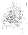
- FIG. 1 is a plan view of a diesel engine.
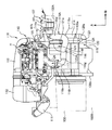
- FIG. 2 is a rear view of the diesel engine.
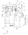
- FIG. 3 is a left side view of the diesel engine taken along arrow III in FIG. (Example 1)
- FIG. 4 is a system diagram of a fuel injection device for a diesel engine.
- FIG. 5 is an enlarged rear view of the fuel injection device taken along arrow V in FIG. (Example 1)
- FIG. 6 is an enlarged side view of the fuel pump taken along arrow VI in FIG.
- FIG. 7 is an enlarged cross-sectional view of the fuel pump taken along line VII-VII in FIG. (Example 1)
- FIG. 8 is a top view of the front portion of the vehicle.
- FIG. 9 is a side view of the front portion of the vehicle.
- FIG. 10 is a rear view of the engine.
- FIG. 11 is a side view of the engine around the intercooler outlet pipe.
- FIG. 12 is a top view of the front portion of the vehicle with the alternator and the intake manifold removed.
- FIG. 13 is a diagram showing the relationship between the engine speed and the charging efficiency in a conventional intercooler outlet pipe having a constant inner diameter and the intercooler outlet pipe of the present embodiment having a different inner diameter.
- FIG. 14 is a side view of the front portion of the vehicle. (Example 3) FIG.
- FIG. 15 is a top view of the front portion of the vehicle.
- FIG. 16 is a front view of the engine.
- FIG. 17 is a rear view of the engine.
- (Example 3) 18 is a view taken in the direction of arrows XVIII-XVIII in FIG. (Example 3)
- FIG. 19 is a perspective view of the EGR device.
- (Example 3) 20 is a cross-sectional view taken along the line XX-XX in FIG.
- FIG. 21 is a view of the periphery of the EGR device as viewed from the front.
- FIG. 22 is a sectional view of the EGR valve.
- a diesel engine (hereinafter referred to as “engine”) 1 is an engine 1 having two cylinders arranged in series.
- the engine 1 has a direction in which two cylinders are aligned as a cylinder row direction A and a direction orthogonal to the cylinder row direction A as a row crossing direction B.
- a cylinder head 3 is disposed above the cylinder block 2
- a cylinder head cover 4 is disposed above the cylinder head 3.
- the cylinder head 3 includes a first cylinder head portion 3a attached to the cylinder block 2 and a second cylinder head portion 3b attached to the first cylinder head portion 3a.
- the cylinder head 3 pivotally supports an intake cam shaft 5 and an exhaust cam shaft 6 extending in the cylinder row direction A between the first cylinder head portion 3a and the second cylinder head portion 3b. Yes.
- the intake camshaft 5 and the exhaust camshaft 6 are arranged in parallel in a row crossing direction B orthogonal to the cylinder row direction A.
- a cylinder head cover 4 that is long in the cylinder row direction A is attached to one side (front side in FIG. 1) of the row crossing direction B at the upper part of the second cylinder head portion 3b.
- a lower case 7 is disposed below the cylinder block 2, and an oil pan 8 is disposed below the lower case 7.
- the cylinder block 2 supports a crankshaft extending in the cylinder row direction A at the lower portion.
- the oil pan 8 protrudes from the cylinder block 2 and the cylinder head 3 on one side in the cylinder row direction A.
- a chain case 9 is disposed on one side of the cylinder block 2 and the cylinder head 3 in the cylinder row direction A and above the oil pan 8.
- a transmission 10 is connected to one side of a cylinder row direction A of the oil pan 8 and a lower portion of one side of the chain case 9 in the cylinder row direction A.
- the engine 1 has an air cleaner 11 disposed above the transmission 10.
- an oil filter 12 and an EGR cooler 13 are arranged in a chain case 9 between the transmission 10 and the air cleaner 11.
- an intake manifold 14 is disposed on the other side (the rear side in FIG. 3) of the column crossing direction B perpendicular to the cylinder row direction A between the cylinder block 2 and the cylinder head 3.
- the engine 1 has an exhaust manifold, a supercharger 15 and an exhaust pipe 16 on one side (front side in FIG. 3) of the cylinder block 2 and the cylinder head 3 in the column crossing direction B orthogonal to the cylinder column direction A.
- a catalyst case 17 is arranged.
- the engine 1 includes a fuel injection device 18 that injects fuel into each cylinder.
- the fuel injection device 18 is supplied from a fuel feed pump 20 that sends out fuel in a fuel tank 19, a fuel supply pipe 21 through which fuel sent by the fuel feed pump 20 flows, and a fuel supply pipe 21.
- a common rail 22 that receives fuel, a plurality of fuel injection valves 23 that inject fuel supplied from the common rail 22 into each cylinder, a fuel supply pipe 21 that connects the fuel tank 19 and the fuel injection valve 23, and
- a fuel pump 24 that is driven by the exhaust camshaft 6 of the engine 1 to boost the fuel, and is disposed upstream of the fuel pump 24 in the fuel supply pipe 21, and is supplied to the fuel pump 24 according to the fuel pressure in the common rail 22.
- the fuel supply pipe 21 is connected from the fuel feed pump 20 of the fuel tank 19 to the fuel injection valve 23 via the flow rate adjustment valve 25, the fuel pump 24, and the common rail 22.
- the fuel supply pipe 21 includes a first fuel supply pipe part 21a that connects the fuel feed pump 20 to the flow rate adjustment valve 25, a second fuel supply pipe part 21b that connects the flow rate adjustment valve 25 to the fuel pump 24, and A third fuel supply piping portion 21c that connects the fuel pump 24 to the common rail 22 and a fourth fuel supply piping portion 21d that connects the common rail 22 to the fuel injection valve 23 are configured. Since the engine 1 of this embodiment has two cylinders, the engine 1 includes two fourth fuel supply pipe portions 21d connected to the two fuel injection valves 23, respectively. Low-pressure fuel sent by the fuel feed pump 20 flows through the first fuel supply piping section 21a and the second fuel supply piping section 21b.
- High-pressure fuel sent by the fuel pump 24 flows through the third fuel supply piping portion 21c and the fourth fuel supply piping portion 21d.
- a fuel filter 27 that filters the fuel supplied to the flow rate adjustment valve 25 is disposed in the first fuel supply piping portion 21a.
- the fuel return pipe 26 is connected to the fuel tank 19 from the fuel injection valve 23, the fuel pump 24, and the flow rate adjustment valve 25 via the junction 28.
- the fuel return pipe 26 includes a first fuel return pipe section 26a that connects the fuel injection valve 23 to the merging section 28, a second fuel return pipe section 26b that connects the fuel pump 24 to the merging section 28, and a flow rate adjustment.
- a third fuel return pipe part 26 c that connects the valve 25 to the junction 28 and a fourth fuel return pipe part 26 d that connects the junction 28 to the fuel tank 19 are configured.
- the fuel injection device 18 purifies the fuel sent from the fuel feed pump 20 in the fuel tank 19 to the first fuel supply piping section 21 a by the fuel filter 27 and sends the fuel to the flow rate adjustment valve 25.
- the flow rate adjusting valve 25 adjusts the fuel to a necessary flow rate, and sends the fuel to the fuel pump 24 through the second fuel supply piping portion 21b.
- the fuel pump 24 sends the boosted fuel to the common rail 22 through the third fuel supply piping portion 21c.
- the common rail 21 distributes the fuel to the fuel injection valves 23 of the respective cylinders by the fourth fuel supply piping portion 21d.
- the fuel injection device 18 includes a fuel pressure sensor 29 that measures the fuel pressure in the common rail 22.
- the fuel pressure sensor 29 outputs the measured fuel pressure to the control unit 30.
- the control unit 30 feeds back the fuel pressure measured by the fuel pressure sensor 29 and adjusts the opening degree of the flow rate adjustment valve 25.
- the flow rate adjustment valve 25 adjusts the flow rate of fuel sent to the fuel pump 24.
- the fuel injection valve 23, the fuel pump 24, and the flow rate adjustment valve 25 allow excess fuel to flow through the first fuel return pipe part 26a, the second fuel return pipe part 26b, and the third fuel return pipe part 26c, respectively.
- the fuel that has flown through the first fuel return pipe part 26a, the second fuel return pipe part 26b, and the third fuel return pipe part 26c is joined at the joining part 28 and returned to the fuel tank 19 by the fourth fuel return pipe part 26d. It is.
- the fuel injection device 18 includes a plurality of fuel injection valves 23 to which fuel is supplied from the common rail 22 in the cylinder row direction A above the second cylinder head portion 3 b constituting the cylinder head 3. They are arranged side by side.
- a common rail 22 is disposed between the two fuel injection valves 23.
- the second cylinder head portion 3 b has a row crossing direction B orthogonal to the cylinder row direction A, and both side portions of the fuel injection valve 23 (rear side portion and front side portion in FIG. 7).
- the intake camshaft 5 and the exhaust camshaft 6 are arranged in the section).
- a fuel pump 24 driven by the exhaust camshaft 6 of the engine 1 is disposed on a fuel supply pipe 21 that connects the fuel tank 19 and the fuel injection valve 23. Further, the fuel injection device 18 is provided with a flow rate adjusting valve 25 for adjusting the flow rate of the fuel supplied to the fuel pump 24 according to the fuel pressure in the common rail 22 on the upstream side of the fuel pump 24 in the fuel supply pipe 21. Yes.
- the fuel injection device 18 connects the fuel feed pump 20 to the flow rate adjustment valve 25 through the first fuel supply piping unit 21a, and connects the flow rate adjustment valve 25 to the fuel pump 24 through the second fuel supply piping unit 21b.
- the common rail 22 is connected to the fuel injection valve 23 by the fourth fuel supply piping section 21d.
- the fuel injection valve 23 is connected to the merging portion 28 by the first fuel return piping portion 26a
- the fuel pump 24 is connected to the merging portion 28 by the second fuel return piping portion 26b
- the flow rate adjusting valve 25 is connected.
- the third fuel return pipe 26c is connected to the junction 28, and the junction 28 is connected to the fuel tank 19 by the fourth fuel return pipe 26d.
- the engine 1 includes a chain case 9 joined to an end portion on the transmission 10 side in the cylinder row direction A between the cylinder block 2 and the cylinder head 3.
- the fuel pump 24 is disposed on the upper surface side of the second cylinder head portion 3 b of the cylinder head 3 and in the vicinity of the end opposite to the chain case 9 in the cylinder row direction A. is doing.
- the fuel pump 24 includes a cylinder member 31 as a pump main body.
- the cylinder member 31 is attached to the pump attachment portion 32 of the second cylinder head portion 3b so as to be inclined toward the intake camshaft 5 side.
- the pump mounting portion 32 includes a communication hole 33 extending in the direction of the exhaust camshaft 6 inside.
- the cylinder member 31 includes a guide hole 34 that faces the exhaust camshaft 6 through a communication hole 33 therein.
- the cylinder member 31 houses the plunger 35 in the guide hole 34 so as to be slidable, that is, in contact with and away from the exhaust camshaft 6.
- the cylinder member 31 is formed with a pump chamber 36 surrounded by an end portion of the plunger 35 opposite to the exhaust cam shaft 6 and an end portion of the guide hole 34.
- the plunger 35 has an end on the side facing the exhaust camshaft 6 protruding from the cylinder member 31 into the communication hole 33 and includes a spring receiving portion 37 at the tip.
- the plunger 35 has a coil spring 38 interposed between the spring receiving portion 37 and the end of the cylinder member 31.
- the coil spring 38 biases the plunger 35 toward the exhaust camshaft 6.
- the plunger 35 has a tappet 39 attached to a spring receiving portion 37.
- the tappet 39 is slidably accommodated in the communication hole 33.
- a roller 40 is rotatably held by the tappet 39.
- the roller 40 is pressed against the pump cam 41 attached to the intake cam shaft 6 by the urging force of the coil spring 38.
- the roller 40 is driven by the rotation of the pump cam 41, moved to the side away from the exhaust cam shaft 6 and the side closer to the exhaust cam shaft 6 in the communication hole 33, and the direction in which the plunger 35 is inserted into the pump chamber 36 via the tappet 39 and the pump chamber. It moves to the direction extracted from 36.
- the plunger 35 moves in the direction to be inserted into the pump chamber 36 by the rotation of the pump cam 41, the plunger 35 pressurizes the pump chamber 36 by reducing the volume of the pump chamber 36.
- the volume of the pump chamber 36 is increased to depressurize the pump chamber 36.
- the fuel pump 24 includes a fuel inlet 42 on the lower side of the cylinder member 31 facing the intake camshaft 5.
- the fuel pump 24 is attached to the upper surface side of the second cylinder head portion 3b so that the fuel inlet 42 is positioned in the vicinity of the intake camshaft 5.
- the fuel inlet 42 communicates with the pump chamber 36.
- the fuel inlet 42 is connected to the second fuel supply piping portion 21b.
- the fuel pump 24 sucks the fuel in the second fuel supply pipe portion 21b from the fuel inlet 42 into the pump chamber 36 which has been decompressed by extracting the plunger 35.
- the fuel pump 24 includes a fuel outlet 43 on the tip end side of the cylinder member 31.
- the fuel outlet 43 communicates with the pump chamber 36.
- the fuel outlet 43 is connected to the third fuel supply pipe 21c.
- the fuel pump 24 discharges the pressurized fuel from the pump chamber 36 pressurized by the insertion of the plunger 35 from the fuel outlet 43 to the third fuel supply piping portion 21c.
- the fuel discharged to the third fuel supply piping part 21 c is supplied to the common rail 22.
- the common rail 22 distributes an equal amount of fuel to the plurality of fuel injection valves 23 by the fourth fuel supply pipe portion 21d.
- the plurality of fuel injection valves 23 inject fuel into each cylinder.
- the fuel pump 24 includes a fuel return outlet 44 in the cylinder member 31.
- the fuel return outlet 44 communicates with the pump chamber 36.
- the fuel return outlet 44 is connected to the second fuel return pipe portion 26b.
- a check valve (not shown) is disposed in the pump chamber 36 to prevent the fuel from flowing back from the common rail 22 or the second fuel return pipe portion 26b to the pump chamber 36 side.
- the second fuel return pipe part 26b is connected to the joining part 28 together with the third fuel return pipe part 26c, and is connected to the fuel tank 19 by the fourth fuel return pipe part 26d.
- the surplus fuel discharged to the second fuel return pipe portion 26 b is returned to the fuel tank 19. For this reason, it is possible to prevent the fuel pressure supplied to the fuel injection valve 23 from rising excessively.
- Reference numeral 45 denotes a pump cover.
- the fuel injection device 18 has a flow rate adjustment valve 25 joined to an end portion on the transmission 10 side in the cylinder row direction A of the cylinder head 3, and on the left side of the vehicle body from the main body portion of the cylinder head 3. It is attached to a chain case 9 protruding to The flow rate adjustment valve 25 supplies the fuel sent from the fuel tank 19 by the fuel feed pump 20 to the fuel pump 24.
- the flow rate adjustment valve 25 has a base portion 46 fixed to the chain case 9 and a cylindrical portion 47 extending from the base portion 46 to the outside of the engine 1.
- the flow rate adjusting valve 25 has a base portion 46 fixed to an attachment portion 49 of a wall surface 48 facing the transmission 10 side of the case 9.
- the flow rate adjusting valve 25 is attached in the vicinity of the intake camshaft 5 on the other side (the rear side in FIGS. 1 and 7) of the row crossing direction B orthogonal to the cylinder row direction A of the chain case 9.
- the fuel injection device 18 of the engine 1 since the fuel injection device 18 of the engine 1 has the flow rate adjusting valve 25 separately from the fuel pump 24 attached to the engine 1, the structure of the fuel pump 24 can be simplified, and the manufacturing cost of the fuel pump 24 can be reduced. . Further, the fuel injection device 18 attaches the flow rate adjustment valve 25 to the chain case 9 joined to the end of the cylinder head 3 in the cylinder row direction A on the transmission 10 side, while the fuel pump 24 is attached to the upper surface side of the cylinder head 3. In the cylinder row direction A, it is arranged in the vicinity of the end opposite to the chain case 9.
- the fuel injection device 18 can be disposed on the transmission 10 side where the flow rate adjusting valve 25 is relatively easy to secure a space, and at a position away from the fuel pump 24 in the cylinder row direction A. Further, the fuel injection device 18 can be compactly arranged near the cylinder head 3 by forming the fuel supply pipe 21 communicating between the flow rate adjusting valve 25 and the fuel pump 24 in a shape with a relatively small bend, and the fuel supply. The connection workability of the piping 21 can be improved. Therefore, the fuel injection device 18 of the engine 1 can reduce the cost of the fuel injection device 18 and can efficiently arrange the components constituting the fuel injection device 18 in the vicinity of the cylinder head 3.
- the engine 1 is an engine 1 having two cylinders. Accordingly, the fuel injection device 18 can adjust the flow rate more efficiently if the above-described structure is applied to the two-cylinder engine 1 having a short length in the cylinder row direction and a small space for mounting the flow rate adjustment valve 25.
- the valve 25 can be arranged in the vicinity of the cylinder head 3.
- the base portion 46 of the flow rate adjusting valve 25 having a base portion 46 and a cylindrical portion 47 is fixed to a wall surface 48 of the chain case 9 facing the transmission 10 side.
- the fuel injection device 18 can efficiently arrange the flow rate adjustment valve 25 having the cylindrical portion 47 extending from the base portion 46 in the vicinity of the cylinder head 3 using the space above the transmission 10. .
- an intake camshaft 5 and an exhaust camshaft 6 are disposed on both sides of the fuel injection valve 23 in a row crossing direction B orthogonal to the cylinder row direction A of the cylinder head 3.
- the fuel injection device 18 drives the fuel pump 24 by the exhaust camshaft 6, and attaches the fuel pump 24 to the cylinder head 3 so that the fuel inlet 42 is positioned in the vicinity of the intake camshaft 5, and connects the flow rate adjusting valve 25 to the chain.
- the case 9 is attached in the vicinity of the intake camshaft 5 in a row crossing direction B orthogonal to the cylinder row direction A.
- the fuel injection device 18 can arrange the flow rate adjusting valve 25 at a position close to the fuel inlet 42 of the fuel pump 24 in the row crossing direction B orthogonal to the cylinder row direction A of the cylinder head 3.
- the second fuel supply piping portion 21 b that communicates between the pumps 24 can be efficiently disposed in the vicinity of the cylinder head 3.
- Example 2 relates to an intake device for an engine with a supercharger provided with an intercooler that cools air introduced from the supercharger into an engine as an internal combustion engine.
- an engine of a vehicle such as an automobile is provided with an intercooler that cools air that is supercharged by a compressor of a supercharger and rises in temperature.
- the charging efficiency of the engine can be increased by lowering the temperature of the air through heat exchange with the outside air passing through the core portion.
- Patent Document 3 Japanese Patent Laid-Open No. 2011-21571
- Patent Document 4 Japanese Patent Laid-Open No. 2009-227132
- an intercooler is installed in front of the engine mounted in the engine room, and an intake manifold is installed behind the engine and in the upper part of the engine.
- the intercooler and the intake manifold are connected by an intercooler outlet pipe having the same inner diameter.
- the intercooler outlet pipe described in Patent Document 3 is arranged so that the intercooler outlet pipe extends from the upper tank of the intercooler to the upper side of the engine along the other end in the vehicle width direction opposite to the one end in the vehicle width direction on the transmission side of the engine. After extending obliquely upward, it is connected to the intake manifold so as to cross the upper part of the engine from the upper rear part of the engine.
- An air cleaner inlet pipe is installed on the front side in the front-rear direction of the vehicle with respect to the intercooler outlet pipe so as to overlap the front-rear direction of the vehicle.
- the intercooler outlet pipe (third intake pipe) described in Patent Document 4 has the same inner diameter, and the intercooler outlet pipe extends from the lower tank of the intercooler in the vehicle width direction on the transmission side of the engine.
- the vehicle extends obliquely upward of the vehicle toward the upper side of the engine along the other end in the vehicle width direction opposite to the one end.
- an air cleaner inlet pipe is installed on the front side in the front-rear direction of the vehicle with respect to the intercooler outlet pipe so as to overlap in the front-rear direction of the vehicle. For this reason, the traveling wind from the front of the vehicle is blocked by the air cleaner inlet pipe, is difficult to hit the intercooler outlet pipe, and the air flowing through the intercooler outlet pipe cannot be efficiently cooled.
- the air cooled by the intercooler cannot be further cooled by the intercooler outlet piping, and the cooled air cannot be introduced into the engine via the intake manifold. Therefore, the charging efficiency of the engine cannot be increased, and it becomes difficult to improve the output performance of the engine.
- the engine output may be reduced.
- the second embodiment has been made by paying attention to the above-described problems, and can prevent the air flowing through the intercooler outlet pipe from being heated and improve the output performance of the engine.
- the output performance can be prevented from deteriorating.
- the first aspect of the second embodiment is an intake device attached to an engine having a supercharger, which is a surge tank attached to a rear portion in the front-rear direction of the engine and an intake intake pipe provided in an upstream portion of the surge tank.
- An intake manifold having an air outlet, an air cooler installed in front of the engine and having an air outlet pipe, and connected to the turbocharger via an intercooler linelet pipe.
- an intercooler outlet pipe that extends along the widthwise end and is connected to the intake air inlet pipe.
- the intercooler outlet pipe has a larger inner diameter than the larger diameter section and the larger diameter section.
- a small-diameter portion having a small inner diameter dimension, and the large-diameter portion from the central portion in the longitudinal direction of the intercooler outlet pipe. And a one formed until the downstream end connected.
- the vehicle width direction end of the engine is supported by the vehicle body via the mounting device, and is heated at the time of operation at the rear in the front-rear direction of the engine and below the surge tank.
- the intake pipe is extended from the surge tank to the lower part of the vehicle and at least the lower part of the auxiliary machine in the height direction of the vehicle, and the air outlet pipe part in the height direction of the vehicle. Is installed above the mounting device, the auxiliary equipment is installed below the mounting device, and the intercooler outlet pipe is connected from the air outlet pipe to the intake air inlet pipe through the mounting device and the auxiliary equipment.
- the large-diameter portion passes through the lower side of the mounting device and from the rear part of the vehicle in the front-rear direction of the mounting device to the lower side of the auxiliary machine and at least downward from the intake pipe. It may be formed between the up interval position.
- the inner diameter dimension of the large diameter portion may be the same over the length direction of the large diameter portion.
- a large diameter part in the state which looked at the engine from the upper direction, a large diameter part may be installed in the circumference
- the large-diameter portion is continuous with the small-diameter portion, and is continuous with the straight portion and the straight portion passing through the lower portion of the mounting device at a position lower than the upper end portion of the accessory.
- An inclined portion extending from the straight portion toward the lower side of the auxiliary device, a first bending portion that is continuous with the inclined portion and curves from the inclined portion toward the lower side of the auxiliary device, and a first bending portion.
- a second curved portion extending downward from the engine in the vehicle front-rear direction and curved rearward from the engine, and extending downward from the intake pipe.
- a tapered portion whose inner diameter is gradually reduced from the upstream side to the downstream side of the second curved portion, and the tapered portion and the intake air are introduced at the downstream end of the tapered portion.
- intercooler outlet piping is comprised including the large diameter part with a larger internal diameter dimension of an intercooler outlet piping, and the small diameter part with a smaller internal diameter dimension than a large diameter part,
- the large diameter portion is formed between the central portion in the longitudinal direction of the intercooler outlet pipe and the downstream end connected to the intake air introduction pipe.
- the large diameter portion is provided in the downstream portion of the intercooler outlet pipe, the surface area of the downstream portion of the intercooler outlet pipe can be increased and the inner diameter dimension of the downstream portion of the intercooler outlet pipe can be increased.
- the temperature of the air flowing through the intercooler outlet pipe is further lowered by the traveling wind, and the intake efficiency of the engine can be increased more effectively and the output of the engine can be improved more effectively.
- the intake air inlet pipe is extended from the surge tank to the lower side of the vehicle, and extended at least to the lower part of the auxiliary machine in the vehicle height direction, and the intercooler outlet pipe is connected to the air outlet pipe portion.
- the intercooler outlet pipe is connected to the air outlet pipe portion.
- the intercooler outlet pipe and the intake pipe can be installed so as to surround the auxiliary machine from the side to the lower side, and the intercooler outlet pipe and the intake pipe are exposed to the heat rising from the auxiliary machine. Can be prevented.
- the air cooled by the intercooler can be prevented from being heated, and the air flowing through the intercooler outlet pipe can be kept at a low temperature.
- the air cooled by the intercooler can be introduced into the engine from the intercooler outlet piping through the intake manifold, and the charging efficiency of the engine can be further increased and the output performance of the engine can be enhanced more effectively.
- the air outlet pipe is installed above the mounting device in the height direction of the vehicle, and the auxiliary machine is installed below the mounting device, and the intercooler outlet pipe is connected from the air outlet pipe to the bottom of the mounting device. And connected to the intake pipe through the lower part of the accessory.
- the intercooler outlet pipe can be installed low in the vehicle height direction from the front (upstream part) to the rear (downstream part) of the vehicle, and the height direction dimension of the intercooler outlet pipe in the vehicle height direction. Can be long.
- the surface area where the traveling wind introduced into the vehicle from the front of the vehicle hits the intercooler outlet piping can be increased, and the intercooler outlet piping can be cooled efficiently.
- the temperature of the air flowing through the intercooler outlet pipe can be further reduced by the traveling wind, and the charging efficiency of the engine can be increased more effectively.
- the large diameter part located in the downstream part of an intercooler outlet piping can be installed in the position lower than an upstream part in the height direction of a vehicle, the traveling wind which flows through the bottom part (for example, bottom part of an engine room) of a vehicle Large diameter part can be installed at many positions.
- the large diameter portion is provided below the auxiliary machine, it is possible to prevent the large diameter part from being exposed to the heat rising from the auxiliary machine. For this reason, the air cooled by the intercooler can be prevented from being heated, and low-temperature air can be introduced into the engine.
- the intercooler outlet piping is not installed in the space above the auxiliary machine, the space above the auxiliary machine can be expanded. For this reason, the accessory can be easily accessed from above, and the accessory can be easily attached to and detached from the engine. Therefore, the workability of the maintenance work of the auxiliary machine can be improved.
- the intercooler outlet piping is not obstructed by the intercooler outlet piping when the engine is assembled to the vehicle body from below with the intercooler outlet piping attached to the engine.
- the engine can be attached to the vehicle body via a mounting device. For this reason, the engine can be easily assembled to the vehicle body.
- the internal diameter dimension of a large diameter part is formed uniformly over the length direction of a large diameter part, it prevents that an intake pulsation is attenuate
- the intake pulsation can be optimized. For this reason, it is possible to prevent a reduction in the amount of air taken into the engine in the normal operating range of the engine, to improve the charging efficiency of the engine more effectively, and to improve the output of the engine more effectively.
- a large diameter part is installed in the circumference
- more air can be introduced into the engine along the gentle curve with the volume of air passing through the large-diameter portion increased.
- the amount of air taken into the engine can be increased to improve the charging efficiency of the engine more effectively, and the output of the engine can be improved more effectively.
- the large-diameter portion is continuous with the first curved portion that curves from the inclined portion toward the lower side of the auxiliary device, and passes through the lower portion of the auxiliary device in the vehicle width direction.
- a second curved portion that extends toward the lower side of the intake pipe after being bent rearward from the engine in the front-rear direction.
- a tapered portion whose inner diameter is gradually reduced from the upstream side of the second curved portion toward the downstream side is formed at the downstream portion of the second curved portion, and the tapered portion and the intake pipe are provided at the downstream end of the tapered portion.
- the small diameter pipe part to be connected was formed, and the downstream part of the large diameter part constituted by the tapered part and the small diameter pipe part was formed in a curved shape.
- the flow velocity of air can be increased by the small-diameter pipe portion before air is introduced into the intake air introduction pipe. Therefore, air with a high flow rate can be introduced into the surge tank, and the efficiency of filling the air introduced into the engine can be effectively increased.
- FIGS. 8 to 13 are views showing an intake device for an engine with a supercharger according to an embodiment of the present invention.
- a vehicle 101 includes a vehicle body 102, and the vehicle body 102 includes side frames 102 ⁇ / b> A and 102 ⁇ / b> B that extend in the front-rear direction of the vehicle 101 and are installed in the vehicle width direction.
- the vehicle body 102 includes a dash panel 103 in front of the vehicle 101 in the front-rear direction, and the dash panel 103 includes an engine room 104 and a vehicle installed in front of the vehicle 101 in the front-rear direction.
- the vehicle is partitioned into a passenger compartment 105 that is installed behind the front-rear direction 101 and in which the passengers board.
- expressions representing front and rear, such as front and rear, are directions with respect to the front-rear direction of the vehicle 101.
- An engine 106 is installed in the engine room 104, and the engine 106 is supported by the side frame 102A via a mounting device 107 attached to one end 106a in the vehicle width direction.
- the mount device 107 includes a first mount bracket 107a that is fastened to one end 106a in the vehicle width direction of the engine 106, and a second mount bracket 107b that is connected to the first mount bracket 107a and extends toward the side frame 102A. And a mount insulator portion 107c connected to the second mount bracket 107b and attached to the side frame 102A.
- a transmission 108 is provided at the other end 106b in the vehicle width direction of the engine 106, and the transmission 108 is supported by the side frame 102B via a mount device (not shown).
- the vehicle width direction one end portion 106a of the engine 106 constitutes the vehicle width direction end portion of the engine 106 of the second embodiment.
- the engine 106 is provided with a supercharger 109 and an intake device 110.
- the intake device 110 is provided in front of the engine 106, an intake duct 111 that takes in air from the front of the vehicle 101, and an air cleaner 112 that is connected to the downstream end of the intake duct 111 and purifies the air.
- an air cleaner outlet pipe 113 for introducing the air purified by the air cleaner 112 into the compressor housing 109a of the supercharger 109.
- the supercharger 109 includes a compressor (not shown) provided inside the compressor housing 109a and a turbine housing 109b containing a turbine (not shown) that is rotated by the pressure of the exhaust gas.
- the intake device 110 includes an intercooler line 114, an intercooler 115, an intercooler outlet line 116, and an intake manifold 117.
- the upstream end of the intercool line pipe 114 is connected to the compressor housing 109a of the supercharger 109, and the downstream end of the inter cool line pipe 114 is connected to the inter cooler 115.
- the upstream end 116 a of the intercooler outlet pipe 116 is connected to the intercooler 115, and the downstream end 116 b of the intercooler outlet pipe 116 is connected to the intake manifold 117.
- upstream and downstream represent upstream and downstream with respect to the direction of air flow.
- the supercharger 109 supercharges the air introduced into the compressor housing 109a from the air cleaner outlet pipe 113 to the intercooler line pipe 114 by a compressor that rotates integrally with a turbine that rotates under the pressure of exhaust gas.
- the hot air is introduced into the intercooler 115 and cooled by the intercooler 115. Thereby, the oxygen density of air is raised.
- the air having an increased oxygen density is introduced into the combustion chamber from the intercooler outlet pipe 116 through the intake manifold 117 and through an intake port (not shown) of the engine 106.
- the intake port is opened and closed by an intake valve (not shown).
- the intercooler 115 is installed in front of the engine 106, and the intercooler 115 includes a core portion 118, an upper tank 119, and a lower tank 120.
- the core part 118 cools the air supplied from the supercharger 109 by the traveling wind, and a circulation part (not shown) through which the air circulates passes in the vertical direction or the vehicle width direction via a running wind flow path (not shown). It is installed side by side.
- the lower tank 120 is provided in the lower part of the core part 118, and the lower tank 120 is provided with an air inlet pipe part 120a to which the intercool line pipe 114 is connected.
- the lower tank 120 introduces air introduced from the intercool linelet pipe 114 through the air inlet pipe part 120 a into the core part 118.
- the upper tank 119 is provided in the upper part of the core part 118, and the upper tank 119 is provided with an air outlet pipe part 119a to which the upstream end 116a of the intercooler outlet pipe 116 is connected (see FIGS. 8 and 9). .
- Air cooled by the core portion 118 is introduced into the upper tank 119, and the air introduced into the upper tank 119 is introduced from the air outlet pipe portion 119a into the intake manifold 117 via the intercooler outlet pipe 116. Is done.
- an alternator 121 is provided at the rear of the engine 106, and a water pump 122 is provided at one end 106 a in the vehicle width direction of the engine 106.
- the alternator 121 constitutes a generator and includes a rotor and a stator (not shown).
- the rotor is rotatably supported by the housing 121A of the alternator 121, and an alternator pulley 121B that protrudes outward from one end 106a in the vehicle width direction of the engine 106 is provided at the end of the rotor. For this reason, the alternator 121 generates high-temperature heat during operation.
- the alternator 121 of this embodiment constitutes an auxiliary machine of the present invention.
- a rotating shaft to which an impeller (not shown) is attached protrudes outward from one end 106a in the vehicle width direction of the engine, and a water pump pulley 122A is attached to the end of the rotating shaft.
- a timing belt 123 is wound around the alternator pulley 121B and the water pump pulley 122A.
- the timing belt 123 is wound around a crank pulley 124.
- the crank pulley 124 is provided at an end portion of a crankshaft (not shown) and protrudes outward from one end portion 106a in the vehicle width direction of the engine 106.
- crankshaft rotation of the crankshaft is transmitted to the alternator 121 and the water pump 122 via the timing belt 123, and the alternator 121 and the water pump 122 are driven in synchronization with the rotation of the crankshaft.
- the alternator 121 is installed below the surge tank 125 of the intake manifold 117 and near the vehicle width direction one end portion 106a of the engine 106 opposite to the transmission 108. It is installed in the center of the engine 106 in the vertical direction.
- the intake manifold 117 is attached to the rear portion of the engine 106, and includes a surge tank 125 that distributes intake air to the engine 106 and an intake introduction pipe 126 that is provided upstream of the surge tank 125.
- a small arrow indicated by an arrow W1 indicates a direction in which air flows.
- the intake intake pipe 126 extends from the surge tank 125 to the lower side of the vehicle 101 and extends to the lower portion 121 a of the alternator 121 in the height direction of the vehicle 101.
- the intercooler outlet pipe 116 extends from the air outlet pipe portion 119a of the intercooler 115 along the vehicle width direction one end portion 106a of the engine 106, and then the downstream end 116b is connected to the intake air introduction pipe 126. ing.
- the air outlet pipe portion 119 a is installed above the mounting device 107 in the height direction of the vehicle 101, and the alternator 121 includes the first mounting bracket 107 a or the mounting device 107. It is installed below the second mount bracket 107b.
- the height of the air outlet pipe part 119a is shown with the code
- the intercooler outlet pipe 116 passes from below the first mount bracket 107 a or the second mount bracket 107 b constituting the mount device 107 from the air outlet pipe portion 119 a and then connects to the intake inlet pipe 126 through the lower portion of the alternator 121. Has been.
- the intercooler outlet piping 116 is configured to include a large diameter portion 116A having a larger inner diameter size than the intercooler outlet piping 116 and a small diameter portion 116B having a smaller inner diameter size than the large diameter portion 116A.
- the large-diameter portion 116A is formed between the central portion C in the longitudinal direction of the intercooler outlet pipe 116 and the downstream end 116b connected to the intake air introduction pipe 126. As shown in FIGS. In a state where 106 is viewed from above, the large diameter portion 116 ⁇ / b> A is installed around the alternator 121 on the lower side of the alternator 121.
- the air outlet pipe portion 119a is installed above the mount device 107, and the alternator 121 is below the first mount bracket 107a or the second mount bracket 107b. is set up.
- the intercooler outlet pipe 116 is connected from the air outlet pipe portion 119a to the intake inlet pipe 126 through the first mount bracket 107a or the second mount bracket 107b and the alternator 121.
- the large-diameter portion 116A is located below the first mount bracket 107a or the second mount bracket 107b and from the rear of the mount device 107 below the alternator 121 and spaced downward from the intake introduction pipe 126.
- the inner diameter dimension of the large diameter portion 116A installed in this range is the same over the length direction of the large diameter portion 116A.
- the large diameter portion 116 ⁇ / b> A is connected to the small diameter portion 116 ⁇ / b> B via a tapered tip portion, and is located at a position lower than the upper end portion 121 b of the alternator 121 and constitutes the mounting device 107.
- a straight portion 116 c that passes below the second mount bracket 107 b and an inclined portion 116 d that is continuous with the straight portion 116 c and extends from the straight portion 116 c toward the lower side of the alternator 121 are provided.
- the large-diameter portion 116A is continuous with the inclined portion 116d and is curved toward the lower side of the alternator 121 from the inclined portion 116d.
- the large-diameter portion 116A is continuous with the curved portion 116e and extends below the alternator 121 in the vehicle width direction.
- a curved portion 116 f that passes and curves toward the rear of the engine 106 and then extends toward the lower side of the intake air intake pipe 126 is provided.
- the bending portion 116e constitutes the first bending portion of the present invention
- the bending portion 116f constitutes the second bending portion of the second embodiment.
- a tapered portion 116g whose inner diameter dimension gradually decreases from the upstream side to the downstream side of the curved portion 116f is formed at the downstream portion of the curved portion 116f, and the tapered portion 116g and the intake air are formed at the downstream end of the tapered portion 116g.
- the downstream portion constituted by the tapered portion 116g and the small diameter tube portion 116h is formed in a curved shape.
- the large diameter portion 116A is integrally formed from the upstream end of the large diameter portion 116A toward the downstream end, and the downstream end of the small diameter pipe portion 116h constitutes the downstream end 116b of the intercooler outlet pipe 116. Further, the upstream end of the small diameter portion 116B constitutes the upstream end 116a of the intercooler outlet pipe 116.
- FIG. 11 the range from the straight part 116c to the inclined part 116d and the curved parts 116e, 116f is shown.
- This intake pulsation is generated when a reflected wave is generated by opening and closing the intake valve, and the reflected wave flows from the intake manifold 117 through the intercooler outlet pipe 116 to the intercooler 115 and rebounds at the air outlet pipe portion 119a of the intercooler 115. A wave is generated.
- the intercooler outlet piping 116 When the intercooler outlet piping 116 resonates in the normal rotation range (for example, 3000 to 4500 rpm) of the engine 106 due to this standing wave, the intake resistance in the downstream portion of the intercooler outlet piping 116 increases and is sucked into the engine 106. The amount of air that is produced decreases. As a result, the charging efficiency of the engine 106 may decrease in the normal rotation range of the engine 106 and the output of the engine 106 may decrease.
- the intercooler outlet pipe 116 is divided into a large diameter part 116A having a large inner diameter dimension and a small diameter part having a smaller inner diameter dimension than the large diameter part 116A.
- 116B and the large diameter portion 116A is formed from the central portion C in the longitudinal direction of the intercooler outlet pipe 116 to the downstream end 116b connected to the intake air introduction pipe 126.
- the intake pulsation can be shifted to the high rotation range of the engine 106, and the intake pulsation can be optimized. That is, in the intake device 110 of the present embodiment, the intercooler outlet pipe 116 is provided with a large diameter portion 116A, and the natural frequency of the intercooler outlet pipe 116 is increased by increasing the inner diameter dimension and the length dimension of the large diameter section 116A. And the natural frequency can be shifted to a high rotation range of the engine 106.
- the intake pulsation is a reflected wave reflected from the intake valve when a standing wave generated inside the intercooler outlet pipe 116 becomes a pressure wave and a large-diameter portion 116A is provided downstream of the intercooler outlet pipe 116. Therefore, the reflected wave can be transmitted to the air outlet pipe portion 119a of the intercooler 115 through the intercooler outlet pipe 116, and the intake pulsation can be shifted to the high rotation range of the engine 106.
- the resonance frequency is lower than that of the intercooler outlet pipe having the large diameter portion 116A of the present embodiment, and intake pulsation is generated in the normal rotation region of the engine 106. It will shift.
- the pressure of the reflected wave generated by the intake valve suddenly decreases at the portion of the intercooler outlet pipe where the small diameter portion changes to the large diameter portion.
- the reflected wave attenuates before reaching the upstream portion of the outlet pipe 116.
- the intake pulsation cannot be shifted to the high rotation range of the engine 106, and the resonance frequency of the intercooler outlet pipe is in the normal rotation range.
- the pulsation resonates and intake resistance increases downstream of the intercooler outlet pipe.
- FIG. 13 shows the engine speed (rpm) and the charging efficiency (%) of the engine 106 in a conventional intercooler outlet pipe having a constant inner diameter dimension and the intercooler outlet pipe 116 of the present embodiment having a different inner diameter dimension. It is a figure which shows the result measured by experiment.
- the intake device 110 of the present embodiment increases the natural frequency of the intercooler outlet pipe 116 and suppresses the decrease in the attenuation amount of the reflected wave reflected from the intake valve, so that the air outlet pipe portion 119a of the intercooler 115 is provided. A reflected wave can be transmitted.
- the resonance point between the standing wave and the large diameter portion 116A of the intercooler outlet pipe 116 can be moved to the high rotation region, and the intake resistance downstream of the intercooler 115 can be reduced in the normal rotation region of the engine 106. .
- the amount of air taken into the engine 106 in the normal rotation range of the engine 106 can be prevented, the charging efficiency of the engine 106 can be improved, and the output of the engine 106 can be improved.
- the intercooler 115 is installed in front of the engine 106, and the intake manifold 117 is installed in the rear part of the engine 106.
- An alternator 121 that generates high-temperature heat during operation is installed at one end 106a of the engine 106 in the vehicle width direction.
- the intercooler outlet pipe 116 needs to be laid out from the front of the engine 106 to the rear of the engine 106 through the vehicle width direction one end 106a.
- the heat generated by the alternator 121 and rising (shown by an arrow H in FIG. 10) stays above the alternator 121, and the intercooler outlet pipe 116 is installed above the alternator 121.
- the air cooled by the intercooler 115 may be heated by the heat that stays upward.
- the intake device 110 of the present embodiment since the large diameter portion 116A is provided in the downstream portion of the intercooler outlet pipe 116, the surface area of the downstream portion of the intercooler outlet pipe 116 can be increased and the intercooler. The inner diameter of the downstream part of the outlet pipe 116 can be increased.
- the surface area on which the traveling wind W (see FIGS. 9 and 11) introduced into the vehicle 101 from the front of the vehicle 101 hits the intercooler outlet pipe 116 can be increased, and the air having a large flow rate flowing through the large diameter portion 116A is intercooled.
- the outlet pipe 116 can efficiently cool.
- the temperature of the air flowing through the intercooler outlet pipe 116 can be further lowered by the traveling wind W, the intake efficiency of the engine can be increased more effectively, and the output of the engine 106 can be improved more effectively.
- the intake intake pipe 126 is extended from the surge tank 125 to the lower side of the vehicle 101 and is extended to the lower part of the alternator 121 in the height direction of the vehicle 101 to provide intercooler outlet piping.
- 116 is connected to the intake air introduction pipe 126 from the air outlet pipe portion 119a through the lower portion of the first mount bracket 107a or the second mount bracket 107b constituting the mount device and the lower portion of the alternator 121.
- the intercooler outlet pipe 116 and the intake inlet pipe 126 can be installed so as to surround the alternator 121 from the side to the lower side, and the intercooler outlet pipe 116 and the intake inlet pipe 126 are heated by the heat rising from the alternator 121. It can be prevented from being exposed. Therefore, the air cooled by the intercooler 115 can be prevented from being heated, and the air flowing through the intercooler outlet pipe 116 can be kept at a low temperature.
- the air cooled by the intercooler 115 can be introduced into the engine 106 from the intercooler outlet pipe 116 through the intake manifold 117, so that the charging efficiency of the engine 106 can be enhanced and the output performance of the engine 106 can be enhanced.
- the air outlet pipe portion 119a is installed above the first mount bracket 107a or the second mount bracket 107b in the height direction of the vehicle 101, and the alternator 121 is installed in the first mount bracket 107a or the second mount.
- the intercooler outlet pipe 116 is connected from the air outlet pipe portion 119a to the intake inlet pipe 126 through the first mount bracket 107a or the second mount bracket 107b and the alternator 121. .
- the intercooler outlet piping 116 can be installed low in the height direction of the vehicle 101 from the front (upstream portion) to the rear (downstream portion) of the vehicle, and the height of the intercooler outlet piping 116 in the height direction of the vehicle 101.
- the vertical dimension can be increased.
- the surface area where the traveling wind W introduced into the vehicle 101 from the front of the vehicle 101 hits the intercooler outlet pipe 116 can be increased, and the intercooler outlet pipe 116 can be efficiently cooled.
- the temperature of the air flowing through the intercooler outlet pipe 116 can be further reduced by the traveling wind W, and the charging efficiency of the engine 106 can be increased more effectively.
- the large-diameter portion 116A positioned at the downstream portion of the intercooler outlet pipe 116 can be installed at a position lower than the upstream portion in the height direction of the vehicle 101, the traveling wind flowing through the bottom of the engine room 104 is located at a large position.
- the large diameter portion 116A can be installed. For this reason, more traveling wind can be applied more to the large diameter part 116A with a large surface area, and air can be cooled more effectively. Therefore, the charging efficiency of the engine 106 can be increased more effectively.
- the large diameter portion 116A is provided below the alternator 121, it is possible to prevent the large diameter portion 116A from being exposed to heat rising from the alternator 121.
- the air cooled by the intercooler 115 can be prevented from being heated, and low-temperature air can be introduced into the engine 106.
- the intercooler outlet pipe 116 is not installed in the space above the alternator 121, the space above the alternator 121 can be expanded. Therefore, the alternator 121 can be easily accessed from above, and the alternator 121 can be easily attached to and detached from the engine 106. Therefore, the workability of the maintenance work of the alternator 121 can be improved.
- the intercooler outlet pipe 116 is allowed to pass under the first mount bracket 107a or the second mount bracket 107b.
- the intercooler outlet pipe 116 is not obstructed by the intercooler outlet pipe 116.
- the engine 106 can be attached to the side frame 102 ⁇ / b> A via the mount device 107 by directing the mount bracket 107 a toward the second mount bracket 107 b connected to the mount insulator 107 c. For this reason, the engine 106 can be easily assembled to the vehicle body 102.
- the inner diameter dimension of the large diameter portion 116A is formed to be the same over the length direction of the large diameter portion 116A, so that the intake pulsation is attenuated by the large diameter portion 116A. It is possible to optimize the intake air pulsation. For this reason, in the normal operation region of the engine 106, the amount of air taken into the engine 106 can be prevented from decreasing, the charging efficiency of the engine 106 can be improved more effectively, and the output of the engine 106 can be more effectively improved. It can be improved.
- the large-diameter portion 116A is installed around the alternator 121 on the lower side of the alternator 121 when the engine 106 is viewed from above. Therefore, if the large-diameter portion 116A has a curvature radius that draws a gentle curve, more air is introduced into the engine 106 along the gentle curve with the volume of air passing through the large-diameter portion 116A increased. it can. As a result, the amount of air taken into the engine 106 can be increased, the charging efficiency of the engine 106 can be improved more effectively, and the output of the engine 106 can be improved more effectively.
- the large-diameter portion 116A includes the straight portion 116c, the inclined portion 116d, and the curved portions 116e and 116f, so that the amount of air introduced into the engine 106 can be increased and the traveling wind can be increased.
- the surface area of the large diameter portion 116A can be increased.
- the large-diameter portion 116A is curved from the inclined portion 116d toward the lower side of the alternator 121, continues to the curved portion 116d, and passes below the alternator 121 in the vehicle width direction.
- a curved portion 116 f extending downward from the intake pipe 126 after being curved rearward from the engine 106. For this reason, the air flowing from the upstream to the downstream of the intercooler outlet pipe 116 can be introduced into the engine 106 while maintaining the momentum by the centrifugal force when passing through the curved portions 116e and 116f.
- a tapered portion 116g whose inner diameter dimension gradually decreases from the upstream side to the downstream side of the curved portion 116f is formed at the downstream portion of the curved portion 116f, and the tapered portion 116g and the intake air intake pipe 126 are provided at the downstream end of the tapered portion 116g.
- the small-diameter pipe part 116h to be connected was formed, and the downstream part of the large-diameter part 116A constituted by the tapered part 116g and the small-diameter pipe part 116h was formed in a curved shape.
- the auxiliary machine is configured by the alternator 121.
- the auxiliary machine is not limited to the alternator 121 as long as the auxiliary machine generates heat.
- Example 3 relates to a structure in which an auxiliary machine including an EGR valve and an EGR cooler is attached to an engine.
- an auxiliary engine such as an EGR device (Exhaust Gas Recirculation device) is provided in an engine of a vehicle such as an automobile.
- EGR device Exhaust Gas Recirculation device
- a part of the exhaust gas after combustion discharged from the combustion chamber of the engine to the exhaust passage is guided to the intake pipe through the EGR pipe (pipe), and mixed with the intake air flowing through the intake pipe to enter the combustion chamber. It is designed to reflux.
- the flow rate of the exhaust gas flowing through the EGR pipe is adjusted by an EGR valve provided in the EGR pipe.
- This EGR device it is possible to mainly reduce nitrogen oxide (NOx) in the exhaust gas, and to improve fuel efficiency when the engine is partially loaded.
- NOx nitrogen oxide
- the third embodiment is made by paying attention to the above problems, and prevents the EGR valve from being exposed to liquid using the air cleaner while preventing the durability of the air cleaner from deteriorating. Thus, it is possible to prevent the reliability of the EGR valve from being lowered.
- an EGR apparatus including an EGR pipe that recirculates a part of exhaust gas from an exhaust system member to an intake system member and an auxiliary device for exhaust gas recirculation, and the intake system member are inhaled.
- an air cleaner for purifying the air, and a transmission is installed at the end in the vehicle width direction, and the auxiliary machine has an EGR valve for adjusting the flow rate of exhaust gas flowing through the EGR pipe, and the EGR pipe.
- An EGR valve body that includes an EGR cooler that cools flowing exhaust gas, and an EGR valve having a valve body that adjusts the opening degree of the EGR pipe; and a drive actuator that is attached to the EGR valve body and drives the valve body
- the EGR valve and the EGR cooler are arranged side by side in the front-rear direction of the vehicle, and at least one of the EGR valve and the EGR cooler is connected to the end of the engine in the vehicle width direction.
- the air cleaner is mounted on the EGR valve and the EGR cooler via a bracket above the transmission, and at least the drive actuator of the EGR valve is installed between the transmission and the air cleaner in the vertical direction of the vehicle. Yes.
- the bracket is composed of the first bracket and the second bracket, the first front fastening portion is formed at the front end portion in the front-rear direction of the vehicle of the EGR valve, and the air cleaner
- a second front side fastening portion is formed at the front end portion of the vehicle in the front-rear direction
- a first rear side fastening portion is formed at the rear end portion in the front-rear direction of the vehicle of the EGR cooler, and a rear end portion of the air cleaner in the front-rear direction of the vehicle
- a second rear side fastening portion is formed, the first front side fastening portion and the second front side fastening portion are connected via the first bracket, and the first rear side fastening portion and the second rear side fastening portion are connected.
- the parts may be connected via a second bracket.
- the EGR cooler is provided in the EGR cooler body and the EGR cooler body, and has an exhaust gas inlet pipe portion through which exhaust gas is introduced from the EGR valve.
- the EGR valve is installed closer to the lower part of the air cleaner than the transmission, the axis of the exhaust gas inlet pipe is inclined outward in the vehicle width direction with respect to the axis of the EGR cooler body, and the axis of the EGR valve is connected to the exhaust gas inlet pipe
- the EGR valve may be extended below the air cleaner so as to be orthogonal to the axis of the part, and the drive actuator may be installed on the opposite side of the engine with respect to the EGR valve body.
- the EGR valve main body protrudes forward from the EGR valve main body in the front-rear direction of the vehicle, has a boss portion that constitutes a first front side fastening portion, and the EGR cooler is connected to the EGR pipe.
- You may have the flange part connected and comprising a 1st back side fastening part.
- the EGR valve may be inclined upward from the EGR valve main body toward the drive actuator in a state where the EGR valve attached to the engine is viewed from the horizontal direction.
- the second front fastening portion of the air cleaner protrudes downward from the lower portion of the air cleaner, and the drive actuator and the second front fastening portion are installed so as to overlap in the vehicle front-rear direction.
- the front of the drive actuator in the front-rear direction of the vehicle may be covered with the second front fastening portion.
- At least the drive actuator for the EGR valve is installed between the transmission and the air cleaner in the vertical direction of the vehicle.
- the air cleaner was attached to the EGR valve and the EGR cooler via a bracket above the transmission. For this reason, it is possible to prevent the bracket from extending from the engine to the air cleaner, and to shorten the dimension of the bracket. Therefore, it is possible to prevent the bracket itself from vibrating due to engine vibration.
- the EGR valve and the EGR cooler are installed side by side in the vehicle front-rear direction, and an air cleaner is attached to the EGR valve and the EGR cooler via a bracket.
- the air cleaner can be supported in a wide range by the EGR valve and the EGR cooler which are relatively rigid and require a relatively large space.
- the air cleaner can be prevented from vibrating due to the vibration of the engine, and the durability of the air cleaner can be prevented from deteriorating.
- the first front side fastening part of the EGR valve and the second front side fastening part of the air cleaner are connected via the first bracket, and the first rear side fastening part of the EGR cooler and The second rear fastening portion of the air cleaner is connected via the second bracket.
- the EGR valve and the EGR cooler can be installed between the front end and the rear end of the air cleaner when the air cleaner is viewed from above.
- a sufficient distance between the front end and the rear end of the air cleaner can be secured, and the air cleaner can be supported in a wide range by the EGR valve and the EGR cooler. Therefore, it is possible to more effectively prevent the air cleaner from vibrating.
- the EGR valve in the vertical direction of the vehicle, is installed closer to the lower portion of the air cleaner than the transmission, and the axis of the exhaust gas inlet pipe is set to the vehicle width with respect to the axis of the EGR cooler body.
- the EGR valve extends to the lower part of the air cleaner so that the axis of the EGR valve is perpendicular to the axis of the exhaust gas inlet pipe, and the drive actuator is installed on the opposite side of the engine from the EGR valve body. did.
- the EGR valve can be reliably installed near the lower portion of the air cleaner, and in particular, the drive actuator can be reliably covered with the air cleaner. Therefore, for example, when an air hole communicating with the atmosphere is formed in the drive actuator like a diaphragm type EGR valve, it is possible to prevent liquid from entering the drive actuator from the air hole. As a result, it is possible to prevent liquid from entering the valve body through the drive actuator, and to prevent deterioration and corrosion of the valve body.
- the first front side fastening part of the EGR valve can be brought close to the second front side fastening part of the air cleaner, and the dimensions of the first bracket can be shortened.
- the EGR valve main body protrudes forward from the EGR valve main body in the front-rear direction of the vehicle, has the boss portion constituting the first front side fastening portion, and the EGR cooler is connected to the EGR pipe. And having a flange portion constituting the first rear fastening portion.
- the rigid boss portion and flange portion can be attached to the air cleaner via the first flange and the second flange, and the air cleaner can be stably attached to the EGR valve and the EGR cooler. Therefore, it is possible to more effectively prevent the air cleaner from vibrating due to the vibration of the engine, and it is possible to more effectively prevent the durability of the air cleaner from deteriorating.
- the EGR valve is inclined upward from the EGR valve main body toward the drive actuator in a state where the EGR valve attached to the engine is viewed from the horizontal direction.
- the drive actuator can be brought close to the bottom of the air cleaner, and the liquid dropped from above can be blocked by the air cleaner. Therefore, when the drive actuator has an air hole or the like, water can be more effectively prevented from entering the drive actuator through the air hole.
- the liquid that enters from the front of the vehicle during the traveling of the vehicle is second front side fastening portion. Can be blocked by. For this reason, when the drive actuator has an air hole or the like, water can be prevented from entering the drive actuator through the air hole.
- FIGS. 14 to 22 are views showing an engine accessory mounting structure according to the third embodiment.
- a vehicle 201 includes a vehicle body 202, and the vehicle body 202 includes a dash panel 203 in front of the vehicle 201 in the front-rear direction.
- the dash panel 203 divides the vehicle body 202 into an engine room 204 installed at the front in the front-rear direction of the vehicle 201 and a vehicle compartment 205 installed at the rear in the front-rear direction of the vehicle for passengers to board.
- expressions indicating the front-rear direction such as front and rear are used in the description as directions relative to the front-rear direction of the vehicle 201.
- An engine 206 is installed in the engine room 204, and a transmission 207 is attached to one end (left end) 206a in the vehicle width direction of the engine 206 as shown in FIGS.
- the vehicle width direction one end portion 206a of the engine 206 constitutes the vehicle width direction end portion of the present invention.
- the engine 206 is provided with a supercharger 208 and an intake device 209.
- the intake device 209 includes an air cleaner 210 installed at one end 206a in the vehicle width direction of the engine 206 and at the top of the transmission 207.
- the air cleaner 210 is sucked from the front of the vehicle 201 by an intake duct (not shown). Purify the air.
- the intake device 209 includes an air cleaner outlet pipe 211 that introduces the air purified by the air cleaner 210 into the compressor housing 208 a of the supercharger 208.
- the supercharger 208 is installed in front of the engine 206, and the supercharger 208 includes a compressor (not shown) provided inside the compressor housing 208a and a turbine (not shown) that is rotated by the pressure of exhaust gas. And a housing 208b.
- the intake device 209 includes an intercool line pipe 212 (see FIG. 16), and the inter cool line pipe 212 is connected to an unshown intercooler installed in front of the engine 206.
- the intake device 209 includes an intake manifold 213, and the intake manifold 213 is installed at the rear portion of the engine 206.
- the intake manifold 213 is connected to the intercooler via an intercooler outlet pipe (not shown).
- the intake manifold 213 introduces intake air introduced from the intercooler through the intercooler outlet into a combustion chamber (not shown) of the engine 206 via an intake port (not shown) of the engine 206.
- the supercharger 208 supercharges the air introduced into the compressor housing 208 a from the air cleaner outlet pipe 211 to the intercooler line pipe 212 by a compressor that rotates integrally with the turbine that rotates under the pressure of the exhaust gas.
- this hot air is introduced into the intercooler and cooled by the intercooler. Thereby, the oxygen density of air is raised.
- the air whose oxygen density has been increased is introduced into the combustion chamber of the engine 206 from the intercooler line 212 through the intake manifold 213.
- an exhaust manifold 214 is attached in front of the engine 206, and the exhaust manifold 214 is connected to the turbine housing 208 b of the supercharger 208. Exhaust gas exhausted from the combustion chamber is introduced into the exhaust manifold 214.
- a catalytic converter 216 is connected to the turbine housing 208b via an exhaust pipe 215. Exhaust gas discharged from the turbine housing 208b is introduced into the catalytic converter 216 through the exhaust pipe 215 and purified by the catalytic converter 216.
- the intake device 209 and the compressor housing 208a of the supercharger 208 constitute an intake system member of the present invention
- the exhaust manifold 214, the exhaust pipe 215, the catalytic converter 216, and the turbine housing 208b of the supercharger 208 are The exhaust system member of the invention is configured.
- the engine 206 is provided with an EGR device 217.
- the EGR device 217 includes an EGR inlet (Exhaust Gas Recirculation) pipe (pipe) 218, an EGR valve 219, an EGR cooler 220, and an EGR outlet pipe (pipe) 221.
- the upstream end 218a of the EGR inlet pipe 218 is connected to the exhaust manifold 214, and the downstream end 218b of the EGR inlet pipe 218 is connected to the EGR valve 219.
- the EGR valve 219 constitutes an adjustment valve that adjusts the flow rate of the exhaust gas.
- upstream and downstream represent directions in which exhaust gas flows.
- An EGR cooler 220 is connected to the EGR valve 219.
- the EGR cooler 220 is provided at the front end of the EGR cooler main body 220A and the EGR cooler main body 220A.
- An exhaust gas outlet pipe portion 220C provided at the rear end portion of the EGR cooler main body 220A and connected to the EGR outlet pipe 221.
- Exhaust gas is introduced from the EGR valve 219 into the exhaust gas inlet pipe 220B, and this exhaust gas is introduced into the EGR cooler body 220A.
- the exhaust gas outlet pipe section 220C discharges exhaust gas from the EGR cooler body 220A to the EGR outlet pipe 221.
- an EGR cooler main body 220A includes an inner pipe (not shown) through which exhaust gas flows, and an outer pipe that surrounds the inner pipe and forms a cooling water passage through which cooling water flows between the inner pipe. 220a.
- the outer pipe 220a is provided with an introduction pipe 222A for introducing cooling water into the cooling water passage and a discharge pipe 222B for discharging cooling water from the cooling water passage, and the cooling water cooled by a radiator (not shown) is introduced into the introduction pipe 222A. Through the cooling water passage. For this reason, the exhaust gas flowing through the inlet pipe of the EGR cooler main body 220A is cooled by the cooling water.
- the upstream end 221a of the EGR outlet pipe 221 is connected to the EGR cooler 220, and the downstream end 221b of the EGR outlet pipe 221 is connected to the intake manifold 213.
- the EGR inlet pipe 218 and the EGR outlet pipe 221 constitute the EGR pipe of the present invention.
- the EGR device 217 having the above configuration introduces part of the exhaust gas discharged to the exhaust manifold 214 from the EGR inlet pipe 218 to the intake manifold 213 via the EGR valve 219, the EGR cooler 220, and the EGR outlet pipe 221. .
- the EGR valve 219 and the EGR cooler 220 of the EGR device 217 include an exhaust gas recirculation auxiliary device that recirculates a part of the exhaust gas from the exhaust system member to the intake system member through the EGR pipe (pipe).
- the EGR valve 219 includes an EGR valve body 223 and a drive actuator 224.
- the EGR valve body 223 includes a lower casing 225 in which an exhaust gas inlet 225 a into which exhaust gas from the EGR inlet pipe 218 is introduced and an exhaust gas outlet 225 b through which exhaust gas is discharged to the EGR cooler 220 are formed. I have.
- a valve shaft 226 is slidably provided inside the lower casing 225, and a valve body 227 is attached to the tip of the valve shaft 226.
- the valve body 227 opens and closes the exhaust gas inlet portion 225a.
- the drive actuator 224 includes an upper casing 228 attached to the lower casing 225, and a diaphragm 229 and a coil spring 230 are accommodated in the upper casing 228.
- the diaphragm 229 partitions the upper casing 228 into a negative pressure chamber 231 and an atmospheric chamber 232, and the coil spring 230 urges the diaphragm 229 downward.
- the upper end of the valve shaft 226 is attached to the diaphragm 229.
- the valve body 227 closes the exhaust gas inlet 225a.
- a negative pressure tube 233 (see FIG. 18) is attached to the negative pressure chamber 231, and the negative pressure generated in the negative pressure chamber 231 is introduced into the negative pressure chamber 231 through the negative pressure tube 233.
- the diaphragm 229 opens the exhaust gas inlet 225a against the biasing force of the coil spring 230. Thereby, the exhaust gas inlet part 225a and the exhaust gas outlet part 225b communicate.
- air holes 228a are formed in the upper casing 228, and a plurality of air holes 228a are formed along the circumferential direction of the upper casing 228 (see FIG. 19).
- the EGR valve 219 and the EGR cooler 220 are installed side by side in the front-rear direction of the vehicle 201.
- the outer pipe 220a of the EGR cooler main body 220A is provided with a pair of brackets 220b protruding toward one end in the vehicle width direction of the engine 206, and the bracket 220b is attached to one end 206a in the vehicle width direction of the engine 206.
- the EGR valve 219 may be attached to the engine 206, and both the EGR cooler 220 and the EGR valve 219 may be attached to the engine 206.
- the air cleaner 210 is attached to the EGR valve 219 and the EGR cooler 220 via brackets 235 and 236 above the transmission 207, and in the vertical direction of the vehicle 201, the EGR valve main body 223 of the EGR valve 219 and The drive actuator 224 is installed between the transmission 207 and the air cleaner 210 (see FIGS. 16 and 17).
- the bracket 235 constitutes the first bracket of the third embodiment
- the bracket 236 constitutes the second bracket of the third embodiment.
- a pair of boss portions 223a are formed at the front end portion of the outer pipe 220a of the EGR valve main body 223, and the boss portions 223a protrude forward from the EGR valve main body 223.
- a front attachment portion 210A is formed at the front end of the air cleaner 210, and the boss portion 223a is connected to the front attachment portion 210A via a bracket 235.
- the flange part 220c is provided in the exhaust gas outlet pipe part 220C attached to the downstream end of the EGR cooler 220.
- a rear attachment portion 210B is formed at the rear end of the air cleaner 210, and the flange portion 220c is attached to the rear attachment portion 210B via a bracket 236.
- the air cleaner 210 of this embodiment is attached to the EGR valve 219 and the EGR cooler 220 via the brackets 235 and 236.
- the boss portion 223a of the EGR valve 219 of the present embodiment constitutes the first front side fastening portion of the third embodiment
- the front side attachment portion 210A of the air cleaner 210 serves as the second front side fastening portion of the third embodiment.
- the flange portion 220c of the EGR cooler 220 of the present embodiment constitutes the first rear side fastening portion of Example 3
- the rear attachment portion 210B of the air cleaner 210 is the second rear side fastening portion of Example 3. Parts.
- the EGR valve 219 is installed closer to the lower part 210 a of the air cleaner 210 than the transmission 207 in the vertical direction of the vehicle 201.
- the axis A of the exhaust gas inlet pipe 220B is inclined outward in the vehicle width direction with respect to the axis B of the EGR cooler main body 220A. Further, in the EGR valve 219, the axis C of the EGR valve 219 extends to the lower part 210a of the air cleaner 210 so that the axis C of the EGR valve 219 is orthogonal to the axis A of the exhaust gas inlet pipe 220B. On the other hand, it is installed on the opposite side to the engine 206.
- the EGR valve 219 is inclined upward from the EGR valve body 223 toward the drive actuator 224 when the EGR valve 219 attached to the engine 206 is viewed from the horizontal direction. That is, the EGR valve 219 is inclined upward by an angle ⁇ from the EGR valve body 223 toward the drive actuator 224 with respect to the horizontal axis D.
- the front mounting portion 210A of the air cleaner 210 protrudes downward from the lower portion 210a of the air cleaner 210, and the drive actuator 224 and the front mounting portion 210A are installed so as to overlap in the front-rear direction of the vehicle 201. ing. Thereby, the front of the drive actuator 224 is covered with the front mounting portion 210A.
- the diaphragm type EGR valve 219 includes a drive actuator 224 in which an air hole 228a is formed.
- a liquid that has entered the engine room 204 for example, water, enters the upper casing 228 of the drive actuator 224 through the air hole 228a and adheres to the diaphragm 229 to prevent deterioration or corrosion of the diaphragm 229. There is a risk.
- the upper casing 228 may travel along the lower casing 225 and adhere to the valve body 227, which may lead to deterioration or corrosion of the valve body 227. As a result, the reliability of the EGR valve 219 may be reduced.
- the EGR valve 219 and the EGR cooler 220 are installed side by side in the front-rear direction of the vehicle 201, and the EGR cooler 220 is installed at one end 206a in the vehicle width direction of the engine 206.
- the air cleaner 210 is mounted on the EGR valve 219 and the EGR cooler 220 via the brackets 235 and 236 above the transmission 207, and the EGR valve 219 is disposed between the transmission 207 and the air cleaner 210 in the vertical direction of the vehicle 201. Installed.
- the air cleaner 210 is mounted on the EGR valve 219 and the EGR cooler 220 via the brackets 235 and 236 above the transmission 207. For this reason, it is possible to prevent the brackets 235 and 236 from extending from the engine 206 to the air cleaner 210 and to shorten the dimensions of the brackets 235 and 236. Therefore, it is possible to prevent the brackets 235 and 236 from vibrating due to the vibration of the engine 206.
- the EGR valve 219 and the EGR cooler 220 were installed side by side in the front-rear direction of the vehicle 201, and the air cleaner 210 was attached to the EGR valve 219 and the EGR cooler 220 via brackets 235 and 236. For this reason, it is not necessary to provide an EGR pipe between the EGR valve 219 and the EGR cooler 220, and the rigidity of the EGR valve 219 and the EGR cooler 220 can be made relatively high. Further, the air cleaner 210 can be supported in a wide range by the EGR valve 219 and the EGR cooler 220 which are relatively rigid and require a relatively large space.
- the air cleaner 210 can be prevented from vibrating due to the vibration of the engine 206, and the durability of the air cleaner 210 can be prevented from deteriorating.
- the boss portion 223a of the EGR valve 219 and the air cleaner front side mounting portion 210A are connected via the bracket 235, and the flange portion 220c of the EGR cooler 220 and the rear side of the air cleaner 210 are connected.
- the attachment portion 210B is connected via the bracket 236.
- the EGR valve 219 and the EGR cooler 220 can be installed between the front end and the rear end of the air cleaner 210 when the air cleaner 210 is viewed from above. Accordingly, a sufficient distance between the front end and the rear end of the air cleaner 210 can be secured, and the air cleaner 210 can be supported by the EGR valve 219 and the EGR cooler 220 in a wide range. Therefore, it is possible to more effectively prevent the air cleaner 210 from vibrating.
- the EGR valve 219 is installed closer to the lower part 210a of the air cleaner 210 than the transmission 207 in the vertical direction of the vehicle 201, and the axis A of the exhaust gas inlet pipe part 220B is The EGR cooler body 220A was inclined outward in the vehicle width direction with respect to the axis B of the main body 220A.
- the EGR valve 219 extends to the lower part 210a of the air cleaner 210 so that the axis C of the EGR valve 219 is orthogonal to the axis A of the exhaust gas inlet pipe 220B, and the drive actuator 224 is moved with respect to the EGR valve main body 223. Installed on the opposite side of the engine 206.
- the EGR valve 219 can be reliably installed near the lower part 210 a of the air cleaner 210, and the drive actuator 224 can be reliably covered with the air cleaner 210. Therefore, when the air hole 228a communicating with the atmosphere is formed in the drive actuator 224 like the diaphragm type EGR valve 219, water can be prevented from entering the drive actuator 224 from the air hole 228a.
- boss portion 223a of the EGR valve 219 can be brought close to the front mounting portion 210A of the air cleaner 210, and the dimension of the bracket 235 can be shortened.
- the EGR valve main body 223 has the boss portion 223a protruding forward from the EGR valve main body 223, and the EGR cooler 220 is connected to the upstream end of the EGR outlet pipe 221.
- the flange portion 220c is provided.
- the rigid boss portion 223a and the flange portion 220c can be attached to the air cleaner 210 via the brackets 235 and 236, and the air cleaner 210 can be stably attached to the EGR valve 219 and the EGR cooler 220. Therefore, it is possible to more effectively prevent the air cleaner 210 from vibrating due to the vibration of the engine 206, and it is possible to more effectively prevent the durability of the air cleaner 210 from deteriorating.
- the EGR valve 219 mounted on the engine 206 in a state where the EGR valve 219 mounted on the engine 206 is viewed from the horizontal direction, the EGR valve 219 is moved upward from the EGR valve body 223 toward the drive actuator 224. Tilted.
- the drive actuator 224 can be brought close to the lower part 210a of the air cleaner 210, and the water W dripped from above the engine room 204 can be blocked by the air cleaner 210. Therefore, it is possible to more effectively prevent water from entering the drive actuator 224 through the air hole 228a.
- the front mounting portion 210A of the air cleaner 210 protrudes downward from the lower portion 210a of the air cleaner 210, and the drive actuator 224 and the front mounting portion 210A overlap in the longitudinal direction of the vehicle 201.
- the front of the drive actuator 224 was covered with the front mounting portion 210A.
- the EGR valve of this embodiment is comprised from the diaphragm-type EGR valve 219, it is not limited to this.
- the EGR valve body 223 and the drive actuator 224 are installed below the air cleaner 210, but only the drive actuator 224 having the air holes 228a may be installed below the air cleaner 210.
- the present invention can reduce the cost of a fuel injection device for a diesel engine, and can efficiently arrange the components constituting the fuel injection device in the vicinity of the cylinder head.
- the present invention can also be applied to a gasoline engine equipped with a fuel injection device having a pump.
- Fuel Injection Device 19 Fuel Tank 20 Fuel Feed Pump 21 Fuel Supply Piping 22 Common Rail 23 Fuel Injection Valve 24 Fuel Pump 25 Flow Rate Adjustment Valve 26 Fuel return piping 27 Fuel filter
Abstract
Priority Applications (2)
| Application Number | Priority Date | Filing Date | Title |
|---|---|---|---|
| DE112015000072.0T DE112015000072B4 (de) | 2014-04-04 | 2015-04-03 | Treibstoff-Einspritzvorrichtung für Dieselmaschine |
| CN201580001060.8A CN105339642B (zh) | 2014-04-04 | 2015-04-03 | 柴油发动机的燃料喷射装置 |
Applications Claiming Priority (6)
| Application Number | Priority Date | Filing Date | Title |
|---|---|---|---|
| JP2014-077675 | 2014-04-04 | ||
| JP2014077675A JP6331603B2 (ja) | 2014-04-04 | 2014-04-04 | 過給機付き内燃機関の吸気装置 |
| JP2014-078509 | 2014-04-07 | ||
| JP2014078509A JP6281386B2 (ja) | 2014-04-07 | 2014-04-07 | 車両用内燃機関の補機取付け構造 |
| JP2014083108A JP6248771B2 (ja) | 2014-04-14 | 2014-04-14 | ディーゼルエンジンの燃料噴射装置 |
| JP2014-083108 | 2014-04-14 |
Publications (1)
| Publication Number | Publication Date |
|---|---|
| WO2015152404A1 true WO2015152404A1 (fr) | 2015-10-08 |
Family
ID=54240711
Family Applications (1)
| Application Number | Title | Priority Date | Filing Date |
|---|---|---|---|
| PCT/JP2015/060618 WO2015152404A1 (fr) | 2014-04-04 | 2015-04-03 | Dispositif d'injection de carburant pour moteur diesel |
Country Status (3)
| Country | Link |
|---|---|
| CN (1) | CN105339642B (fr) |
| DE (1) | DE112015000072B4 (fr) |
| WO (1) | WO2015152404A1 (fr) |
Families Citing this family (1)
| Publication number | Priority date | Publication date | Assignee | Title |
|---|---|---|---|---|
| JP6583368B2 (ja) | 2017-08-24 | 2019-10-02 | マツダ株式会社 | 車両用パワートレインユニット |
Citations (8)
| Publication number | Priority date | Publication date | Assignee | Title |
|---|---|---|---|---|
| JPS6350649A (ja) * | 1986-08-20 | 1988-03-03 | Toyota Motor Corp | 内燃機関の燃料噴射制御装置 |
| JPH0542739U (ja) * | 1991-11-01 | 1993-06-11 | 株式会社クボタ | エンジンのクランク軸端部の軸受装置 |
| JPH10238360A (ja) * | 1997-02-25 | 1998-09-08 | Mitsubishi Motors Corp | 内燃機関のカムシャフト構造 |
| JPH11200949A (ja) * | 1998-01-12 | 1999-07-27 | Isuzu Motors Ltd | シリンダブロック構造 |
| JP2002021568A (ja) * | 2000-07-11 | 2002-01-23 | Hachiro Hattori | 内燃機関 |
| JP2003184688A (ja) * | 2001-12-19 | 2003-07-03 | Suzuki Motor Corp | エンジンの燃料ポンプ装置 |
| EP1357256A2 (fr) * | 2002-04-26 | 2003-10-29 | Iveco Motorenforschung AG | Moteur à combustion interne avec une distribution améliorée |
| US20070193558A1 (en) * | 2004-03-15 | 2007-08-23 | Erwin Achleitner | Method and system for controlling an internal combustion engine |
Family Cites Families (10)
| Publication number | Priority date | Publication date | Assignee | Title |
|---|---|---|---|---|
| JPH0828398A (ja) | 1994-07-15 | 1996-01-30 | Mazda Motor Corp | ディーゼルエンジンの燃料噴射装置 |
| DE19725472A1 (de) | 1997-06-17 | 1998-12-24 | Bosch Gmbh Robert | Mengenregelventil |
| JP3683841B2 (ja) | 2001-09-03 | 2005-08-17 | 本田技研工業株式会社 | 内燃機関の吸気装置 |
| JP4626814B2 (ja) | 2005-12-28 | 2011-02-09 | スズキ株式会社 | 車両用エンジンのカバー装置 |
| JP2009227132A (ja) | 2008-03-24 | 2009-10-08 | Mazda Motor Corp | 車体前部構造 |
| JP5229145B2 (ja) | 2009-07-17 | 2013-07-03 | スズキ株式会社 | 車両用エンジンの吸気装置 |
| US8869776B2 (en) | 2011-11-25 | 2014-10-28 | Honda Motor Co., Ltd. | Auxiliary device mounting structure for an internal combustion engine |
| JP6000552B2 (ja) * | 2012-01-19 | 2016-09-28 | ヤンマー株式会社 | エンジン装置 |
| JP5910149B2 (ja) | 2012-02-17 | 2016-04-27 | スズキ株式会社 | 車両用エンジンの燃料ポンプ装置 |
| CN104204488B (zh) * | 2012-03-28 | 2017-03-08 | 洋马株式会社 | 发动机 |
-
2015
- 2015-04-03 CN CN201580001060.8A patent/CN105339642B/zh not_active Expired - Fee Related
- 2015-04-03 DE DE112015000072.0T patent/DE112015000072B4/de active Active
- 2015-04-03 WO PCT/JP2015/060618 patent/WO2015152404A1/fr active Application Filing
Patent Citations (8)
| Publication number | Priority date | Publication date | Assignee | Title |
|---|---|---|---|---|
| JPS6350649A (ja) * | 1986-08-20 | 1988-03-03 | Toyota Motor Corp | 内燃機関の燃料噴射制御装置 |
| JPH0542739U (ja) * | 1991-11-01 | 1993-06-11 | 株式会社クボタ | エンジンのクランク軸端部の軸受装置 |
| JPH10238360A (ja) * | 1997-02-25 | 1998-09-08 | Mitsubishi Motors Corp | 内燃機関のカムシャフト構造 |
| JPH11200949A (ja) * | 1998-01-12 | 1999-07-27 | Isuzu Motors Ltd | シリンダブロック構造 |
| JP2002021568A (ja) * | 2000-07-11 | 2002-01-23 | Hachiro Hattori | 内燃機関 |
| JP2003184688A (ja) * | 2001-12-19 | 2003-07-03 | Suzuki Motor Corp | エンジンの燃料ポンプ装置 |
| EP1357256A2 (fr) * | 2002-04-26 | 2003-10-29 | Iveco Motorenforschung AG | Moteur à combustion interne avec une distribution améliorée |
| US20070193558A1 (en) * | 2004-03-15 | 2007-08-23 | Erwin Achleitner | Method and system for controlling an internal combustion engine |
Also Published As
| Publication number | Publication date |
|---|---|
| CN105339642A (zh) | 2016-02-17 |
| DE112015000072T5 (de) | 2016-02-18 |
| CN105339642B (zh) | 2017-12-26 |
| DE112015000072B4 (de) | 2019-02-07 |
Similar Documents
| Publication | Publication Date | Title |
|---|---|---|
| US8615998B2 (en) | Lubrication device of turbocharger of engine for vehicle | |
| JP7043849B2 (ja) | エンジンの吸排気装置 | |
| JPWO2013073052A1 (ja) | 過給機付き内燃機関 | |
| KR20220122805A (ko) | 엔진 장치 | |
| KR20200130876A (ko) | 엔진 장치 | |
| KR20220025278A (ko) | 엔진 장치 | |
| WO2015152403A1 (fr) | Dispositif d'admission de moteur | |
| CN111051678B (zh) | 带增压器的发动机 | |
| WO2015152374A1 (fr) | Dispositif d'admission pour moteur à combustion interne équipé d'un compresseur | |
| US10900411B2 (en) | Engine with supercharger arrangement | |
| JP5393375B2 (ja) | 内燃機関 | |
| KR102049135B1 (ko) | 엔진장치 | |
| WO2015152404A1 (fr) | Dispositif d'injection de carburant pour moteur diesel | |
| JP2019127917A (ja) | エンジンの吸排気装置 | |
| JP2010138776A (ja) | 燃料供給装置 | |
| JP4321198B2 (ja) | エンジンの吸気装置 | |
| JP2019127916A (ja) | エンジンの吸排気装置 | |
| JP2014012497A (ja) | エンジン装置 | |
| JP5345033B2 (ja) | 内燃機関 | |
| JPH09242548A (ja) | 機械式過給機付エンジンの吸気装置 | |
| JP2021143627A (ja) | エンジンの冷却装置 | |
| JP2022100373A (ja) | エンジン装置 | |
| JP2021143626A (ja) | エンジンの冷却装置 | |
| JP2012197719A (ja) | 排気ガス再循環装置の構造 | |
| JP2011069255A (ja) | 内燃機関の燃料デリバリパイプ |
Legal Events
| Date | Code | Title | Description |
|---|---|---|---|
| WWE | Wipo information: entry into national phase |
Ref document number: 201580001060.8 Country of ref document: CN |
|
| 121 | Ep: the epo has been informed by wipo that ep was designated in this application |
Ref document number: 15773637 Country of ref document: EP Kind code of ref document: A1 |
|
| WWE | Wipo information: entry into national phase |
Ref document number: 1120150000720 Country of ref document: DE Ref document number: 112015000072 Country of ref document: DE |
|
| 122 | Ep: pct application non-entry in european phase |
Ref document number: 15773637 Country of ref document: EP Kind code of ref document: A1 |