WO2015152385A1 - クライオステーションシステム - Google Patents
クライオステーションシステム Download PDFInfo
- Publication number
- WO2015152385A1 WO2015152385A1 PCT/JP2015/060525 JP2015060525W WO2015152385A1 WO 2015152385 A1 WO2015152385 A1 WO 2015152385A1 JP 2015060525 W JP2015060525 W JP 2015060525W WO 2015152385 A1 WO2015152385 A1 WO 2015152385A1
- Authority
- WO
- WIPO (PCT)
- Prior art keywords
- sample
- cryostation
- main body
- space
- heating
- Prior art date
Links
- 238000001816 cooling Methods 0.000 claims abstract description 43
- 238000010438 heat treatment Methods 0.000 claims abstract description 27
- 239000002826 coolant Substances 0.000 claims abstract description 15
- 239000002245 particle Substances 0.000 claims abstract description 13
- 238000005192 partition Methods 0.000 claims abstract description 10
- 238000003860 storage Methods 0.000 claims description 36
- 230000007723 transport mechanism Effects 0.000 claims description 14
- 238000003780 insertion Methods 0.000 claims description 12
- 230000037431 insertion Effects 0.000 claims description 12
- 230000007246 mechanism Effects 0.000 claims description 6
- 238000009835 boiling Methods 0.000 claims description 4
- 238000009833 condensation Methods 0.000 abstract description 12
- 230000005494 condensation Effects 0.000 abstract description 12
- 239000000126 substance Substances 0.000 abstract description 12
- 238000007710 freezing Methods 0.000 abstract description 5
- 230000008014 freezing Effects 0.000 abstract description 5
- 230000015572 biosynthetic process Effects 0.000 abstract description 2
- 238000007599 discharging Methods 0.000 abstract description 2
- 239000000523 sample Substances 0.000 description 181
- 239000002904 solvent Substances 0.000 description 33
- 239000007788 liquid Substances 0.000 description 8
- 238000000034 method Methods 0.000 description 8
- 238000010586 diagram Methods 0.000 description 7
- 239000000463 material Substances 0.000 description 7
- IJGRMHOSHXDMSA-UHFFFAOYSA-N Atomic nitrogen Chemical compound N#N IJGRMHOSHXDMSA-UHFFFAOYSA-N 0.000 description 6
- 239000007789 gas Substances 0.000 description 4
- 239000011347 resin Substances 0.000 description 4
- 229920005989 resin Polymers 0.000 description 4
- XLYOFNOQVPJJNP-UHFFFAOYSA-N water Substances O XLYOFNOQVPJJNP-UHFFFAOYSA-N 0.000 description 4
- -1 for example Substances 0.000 description 3
- 229910052757 nitrogen Inorganic materials 0.000 description 3
- 238000007789 sealing Methods 0.000 description 3
- RYGMFSIKBFXOCR-UHFFFAOYSA-N Copper Chemical compound [Cu] RYGMFSIKBFXOCR-UHFFFAOYSA-N 0.000 description 2
- OTMSDBZUPAUEDD-UHFFFAOYSA-N Ethane Chemical compound CC OTMSDBZUPAUEDD-UHFFFAOYSA-N 0.000 description 2
- 229910052802 copper Inorganic materials 0.000 description 2
- 239000010949 copper Substances 0.000 description 2
- 238000004321 preservation Methods 0.000 description 2
- 230000008569 process Effects 0.000 description 2
- 238000012545 processing Methods 0.000 description 2
- 239000012472 biological sample Substances 0.000 description 1
- 230000005540 biological transmission Effects 0.000 description 1
- 230000000903 blocking effect Effects 0.000 description 1
- 230000008859 change Effects 0.000 description 1
- 238000001704 evaporation Methods 0.000 description 1
- 230000008020 evaporation Effects 0.000 description 1
- 238000004108 freeze drying Methods 0.000 description 1
- 239000012520 frozen sample Substances 0.000 description 1
- 238000002309 gasification Methods 0.000 description 1
- 238000009434 installation Methods 0.000 description 1
- 238000009413 insulation Methods 0.000 description 1
- 238000004519 manufacturing process Methods 0.000 description 1
- 238000005259 measurement Methods 0.000 description 1
- 239000002184 metal Substances 0.000 description 1
- 229910052751 metal Inorganic materials 0.000 description 1
- 239000007769 metal material Substances 0.000 description 1
- 238000012986 modification Methods 0.000 description 1
- 230000004048 modification Effects 0.000 description 1
- 238000012856 packing Methods 0.000 description 1
- 238000002360 preparation method Methods 0.000 description 1
- 229910052709 silver Inorganic materials 0.000 description 1
- 239000004332 silver Substances 0.000 description 1
Images


Classifications
-
- H—ELECTRICITY
- H01—ELECTRIC ELEMENTS
- H01J—ELECTRIC DISCHARGE TUBES OR DISCHARGE LAMPS
- H01J37/00—Discharge tubes with provision for introducing objects or material to be exposed to the discharge, e.g. for the purpose of examination or processing thereof
- H01J37/02—Details
- H01J37/20—Means for supporting or positioning the object or the material; Means for adjusting diaphragms or lenses associated with the support
-
- F—MECHANICAL ENGINEERING; LIGHTING; HEATING; WEAPONS; BLASTING
- F25—REFRIGERATION OR COOLING; COMBINED HEATING AND REFRIGERATION SYSTEMS; HEAT PUMP SYSTEMS; MANUFACTURE OR STORAGE OF ICE; LIQUEFACTION SOLIDIFICATION OF GASES
- F25D—REFRIGERATORS; COLD ROOMS; ICE-BOXES; COOLING OR FREEZING APPARATUS NOT OTHERWISE PROVIDED FOR
- F25D3/00—Devices using other cold materials; Devices using cold-storage bodies
- F25D3/10—Devices using other cold materials; Devices using cold-storage bodies using liquefied gases, e.g. liquid air
- F25D3/102—Stationary cabinets
-
- B—PERFORMING OPERATIONS; TRANSPORTING
- B01—PHYSICAL OR CHEMICAL PROCESSES OR APPARATUS IN GENERAL
- B01L—CHEMICAL OR PHYSICAL LABORATORY APPARATUS FOR GENERAL USE
- B01L7/00—Heating or cooling apparatus; Heat insulating devices
- B01L7/04—Heat insulating devices, e.g. jackets for flasks
-
- B—PERFORMING OPERATIONS; TRANSPORTING
- B01—PHYSICAL OR CHEMICAL PROCESSES OR APPARATUS IN GENERAL
- B01L—CHEMICAL OR PHYSICAL LABORATORY APPARATUS FOR GENERAL USE
- B01L7/00—Heating or cooling apparatus; Heat insulating devices
- B01L7/50—Cryostats
-
- F—MECHANICAL ENGINEERING; LIGHTING; HEATING; WEAPONS; BLASTING
- F25—REFRIGERATION OR COOLING; COMBINED HEATING AND REFRIGERATION SYSTEMS; HEAT PUMP SYSTEMS; MANUFACTURE OR STORAGE OF ICE; LIQUEFACTION SOLIDIFICATION OF GASES
- F25D—REFRIGERATORS; COLD ROOMS; ICE-BOXES; COOLING OR FREEZING APPARATUS NOT OTHERWISE PROVIDED FOR
- F25D21/00—Defrosting; Preventing frosting; Removing condensed or defrost water
- F25D21/04—Preventing the formation of frost or condensate
-
- F—MECHANICAL ENGINEERING; LIGHTING; HEATING; WEAPONS; BLASTING
- F25—REFRIGERATION OR COOLING; COMBINED HEATING AND REFRIGERATION SYSTEMS; HEAT PUMP SYSTEMS; MANUFACTURE OR STORAGE OF ICE; LIQUEFACTION SOLIDIFICATION OF GASES
- F25D—REFRIGERATORS; COLD ROOMS; ICE-BOXES; COOLING OR FREEZING APPARATUS NOT OTHERWISE PROVIDED FOR
- F25D3/00—Devices using other cold materials; Devices using cold-storage bodies
- F25D3/10—Devices using other cold materials; Devices using cold-storage bodies using liquefied gases, e.g. liquid air
- F25D3/105—Movable containers
-
- G—PHYSICS
- G01—MEASURING; TESTING
- G01N—INVESTIGATING OR ANALYSING MATERIALS BY DETERMINING THEIR CHEMICAL OR PHYSICAL PROPERTIES
- G01N1/00—Sampling; Preparing specimens for investigation
- G01N1/28—Preparing specimens for investigation including physical details of (bio-)chemical methods covered elsewhere, e.g. G01N33/50, C12Q
- G01N1/42—Low-temperature sample treatment, e.g. cryofixation
-
- B—PERFORMING OPERATIONS; TRANSPORTING
- B01—PHYSICAL OR CHEMICAL PROCESSES OR APPARATUS IN GENERAL
- B01L—CHEMICAL OR PHYSICAL LABORATORY APPARATUS FOR GENERAL USE
- B01L2200/00—Solutions for specific problems relating to chemical or physical laboratory apparatus
- B01L2200/06—Fluid handling related problems
- B01L2200/0684—Venting, avoiding backpressure, avoid gas bubbles
-
- B—PERFORMING OPERATIONS; TRANSPORTING
- B01—PHYSICAL OR CHEMICAL PROCESSES OR APPARATUS IN GENERAL
- B01L—CHEMICAL OR PHYSICAL LABORATORY APPARATUS FOR GENERAL USE
- B01L2300/00—Additional constructional details
- B01L2300/18—Means for temperature control
- B01L2300/1838—Means for temperature control using fluid heat transfer medium
- B01L2300/185—Means for temperature control using fluid heat transfer medium using a liquid as fluid
-
- H—ELECTRICITY
- H01—ELECTRIC ELEMENTS
- H01J—ELECTRIC DISCHARGE TUBES OR DISCHARGE LAMPS
- H01J2237/00—Discharge tubes exposing object to beam, e.g. for analysis treatment, etching, imaging
- H01J2237/20—Positioning, supporting, modifying or maintaining the physical state of objects being observed or treated
- H01J2237/2001—Maintaining constant desired temperature
-
- H—ELECTRICITY
- H01—ELECTRIC ELEMENTS
- H01J—ELECTRIC DISCHARGE TUBES OR DISCHARGE LAMPS
- H01J2237/00—Discharge tubes exposing object to beam, e.g. for analysis treatment, etching, imaging
- H01J2237/20—Positioning, supporting, modifying or maintaining the physical state of objects being observed or treated
- H01J2237/2002—Controlling environment of sample
-
- H—ELECTRICITY
- H01—ELECTRIC ELEMENTS
- H01J—ELECTRIC DISCHARGE TUBES OR DISCHARGE LAMPS
- H01J2237/00—Discharge tubes exposing object to beam, e.g. for analysis treatment, etching, imaging
- H01J2237/20—Positioning, supporting, modifying or maintaining the physical state of objects being observed or treated
- H01J2237/202—Movement
- H01J2237/20214—Rotation
-
- H—ELECTRICITY
- H01—ELECTRIC ELEMENTS
- H01J—ELECTRIC DISCHARGE TUBES OR DISCHARGE LAMPS
- H01J2237/00—Discharge tubes exposing object to beam, e.g. for analysis treatment, etching, imaging
- H01J2237/20—Positioning, supporting, modifying or maintaining the physical state of objects being observed or treated
- H01J2237/202—Movement
- H01J2237/20221—Translation
- H01J2237/20235—Z movement or adjustment
-
- H—ELECTRICITY
- H01—ELECTRIC ELEMENTS
- H01J—ELECTRIC DISCHARGE TUBES OR DISCHARGE LAMPS
- H01J2237/00—Discharge tubes exposing object to beam, e.g. for analysis treatment, etching, imaging
- H01J2237/20—Positioning, supporting, modifying or maintaining the physical state of objects being observed or treated
- H01J2237/204—Means for introducing and/or outputting objects
Definitions
- the present invention relates to handling of a sample for observation with a charged particle beam apparatus, for example, an electron microscope, and particularly relates to a technique for storing and moving a cooled sample without causing condensation or frost.
- a charged particle beam apparatus for example, an electron microscope
- Patent Document 1 Japanese Patent Laid-Open No. 2013-88328
- specimens of various shapes such as liquid and gel are frozen and replaced after rapid freezing, so that observation samples by a transmission electron microscope (TEM) can be obtained.
- TEM transmission electron microscope
- Samples that have been subjected to processing such as freezing are transported to the sample holder and then introduced into the charged particle apparatus.
- Patent Document 2 Japanese Patent Application Laid-Open No. 2010-257617
- Patent Document 3 Japanese Patent Laid-Open No. 2014-10965 describes a sample holder that stably maintains the posture of the cooling source regardless of the inclination of the sample.
- the problem to be solved by the present invention is to prevent the formation of condensation and frost-like substances in the cooled sample during transport to the sample holder, and to perform observation and analysis with a charged particle beam apparatus while maintaining a good frozen state. It is an object to provide an apparatus and a method that make it possible.
- the present invention provides a cryostation system for storing a sample in a cooled state, the main body storing the sample, and a lid placed on the main body.
- the main body is divided into a first space and a second space by a partition member, and a cooling medium for cooling the sample is accommodated in the first space, and the second space Has a heating part for heating the cooling medium accommodated in the first space, and the lid part forms a discharge port for discharging the gas generated by heating the cooling medium to the outside.
- the present invention it is possible to prevent contact of the cooled sample with the atmosphere, so that it can be mounted on the sample holder without generating condensation or frost-like material, and observed and analyzed with a charged particle beam apparatus while maintaining a good state. It becomes possible.
- FIG. 1 shows a schematic configuration diagram of a system for storing and transporting a cooled sample according to an embodiment of the present invention.
- the storage and transport system for the cooled sample may be referred to as a “cryo station system”.
- the cryostation system 100 includes a cryostation body 101, a lid 102, and a temperature adjustment unit 105. Inside the cryostation main body 101, the cooled sample can be stored and transported to the sample holder.
- the cryostation main body 101 is provided with an insertion port 103 into which a sample holder 107 for holding a sample can be inserted, and a connection portion 104 connected to the cable 106 of the temperature adjustment unit 105.
- the temperature adjustment unit 105 includes a display unit that displays the actual internal temperature of the cryostation main body 101 and the target cooling temperature set by the user. Further, the temperature adjustment unit 105 is connected to a temperature sensor 110 and a main body heating unit 111, which will be described later, by wiring (not shown). The actual internal temperature is measured by the temperature sensor 110, and the measurement result is transmitted to the temperature adjustment unit 105 and displayed. Then, according to a command from the temperature adjustment unit 105, the main body heating unit 111 is operated, and the temperature of the cooling solvent accommodated in the cryostation main body 101 is adjusted.
- the temperature is slightly higher than the temperature at which the user houses the cooling medium in the cryostation main body 101 and is stable (for example, about -170 degrees when liquid nitrogen is used as the cooling medium). It is desirable to set a high temperature (for example, ⁇ 168 to ⁇ 169 degrees).
- the main body heating unit 111 is temporarily turned off only when the actual temperature becomes higher than the set temperature, but in other cases, it is basically always on. Can be adjusted to maintain.
- the temperature adjustment unit 105 and the cryostation main-body part 101 were shown about the example connected via the cable 106, you may comprise as an integrated type.
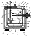
- FIG. 2 shows a schematic diagram when the sample is stored according to the present embodiment.
- a vacuum space 131 is formed between the inner wall 129 and the outer wall 132 of the cryostation main body 101.
- the vacuum space 131 may be evacuated in advance by connecting to an external vacuum pump, and thereafter used without performing evacuation, or may be evacuated each time during use. You may comprise.
- a vacuum sealing holder 112 is inserted into the insertion port 103 in place of the sample holder 107 described later during sample storage.
- the cryostation main body 101 contains the first space 127 in which the first cooling solvent 120 and the second cooling solvent 126 are stored, and the cooling solvent by the partition member 128.
- the second space 130 is not divided.
- a sample storage unit 108 that holds the sample 113 is arranged.
- a space other than the inside of the sample storage unit 108 contains a first cooling solvent, for example, liquid nitrogen.
- the sample storage unit 108 contains a second cooling solvent, for example, liquid ethane.
- a second cooling solvent having a boiling point higher than that of the first cooling solvent.
- first cooling solvent and the second cooling solvent may be the same substance.
- the sample storage unit 108 is fixed by a sample storage unit stand 109.
- the sample 113 is stored while being immersed in the second cooling solvent 126 in the sample storage unit 108.
- the sample storage unit 108 is made of a material having a high thermal conductivity, for example, a metallic material such as silver or copper, and the sample storage unit stand 109 is made of a material having a lower thermal conductivity than the sample storage unit 108, such as a resin. use. This is in consideration of heat conduction by the main body heating unit 111 described later.
- the cryostation main body 101 includes a main body heating section 111 in the second space 130 formed by the partition member 128 and the inner wall 129 in order to heat the first cooling solvent 120 inside.
- the main body heating unit 111 actively gasifies by heating the first cooling solvent 120 and releases the vapor to the outside. Since the vapor
- the installation position of the main body heating unit 111 is a position around one end of the lower surface of the partition member 128 (on the second space 130 side) (the end opposite to the sample storage unit 108), It is desirable to be installed at a location corresponding to the lower part of the exhaust port 121. By comprising in this way, a vapor
- the main body heating unit 111 can be disposed at a position other than the above.
- the temperature of the cryostation main body 101 is measured, and the actual temperature adjustment unit 105 is supplied to the temperature adjustment unit 105. Send internal temperature information and feedback.
- the lid part 102 includes a lid part handle 122, an operation window 124, and an exhaust opening / closing part 125.
- the operation window 124 has an operation window handle 123.
- the exhaust port opening / closing part 125 is partially formed with a step (or hole) serving as an exhaust port, and the exhaust port can be opened and closed by moving a knob 133 as will be described later.
- FIG. 3 shows a top view when the lid portion 102 is installed on the cryostation main body 101, and a cross-sectional view taken along the line X-X ′ (first configuration example).
- the lid portion 102 includes an operation window 124 when the sample 113 is mounted on the sample holder 107, and an exhaust port opening / closing portion 125. Since the exhaust opening / closing portion 125 has a step as shown in the XX ′ cross-sectional view, the cryostation main body portion 101 is moved by moving the knob 133 in any direction of the arrow in the top view. An exhaust port 121 for steam generated inside is formed.
- the operation window 124 has a structure that can be attached and detached.
- the operation window 124 is used after being removed using the operation window handle 123.
- the operation window 124 is preferably made of a material such as a transparent resin so that the contents can be easily confirmed even when attached to the cryostation main body 101.
- FIG. 4 shows a top view when the lid 102 is installed on the cryostation main body 101 and a cross-sectional view taken along the line X-X ′ (second configuration example).
- the exhaust port opening / closing part 125 has a hole in place of the step shape shown in FIG. Therefore, by moving the knob 133 in any direction of the arrow in the top view, an exhaust port 121 for steam generated inside the cryostation main body 101 is formed.
- FIG. 5A shows a perspective view (first configuration example) of the lid according to the embodiment of the present invention.
- This figure corresponds to the configuration of the lid 102 described in FIG.
- the exhaust port opening / closing part 125 is provided with a step 134, and rotates by moving the knob 133 in either direction of the arrow in the figure.
- the opening 135a formed on the lid portion 102 side and the portion provided with the step 134 overlap with each other due to the rotation, the steam generated inside the cryostation main body 101 is the opening portion 135a and the lid portion 102. It exhausts from the opening part 135b provided in the side surface.
- FIG. 5B shows a perspective view (second configuration example) of the lid according to the embodiment of the present invention.
- This figure corresponds to the configuration of the lid 102 described in FIG.
- the exhaust port opening / closing part 125 is provided with an opening 136, and rotates by moving the knob 133 in either direction of the arrow in the figure.
- Vapor generated inside the cryostation main body 101 when the opening 135a formed on the lid 102 side overlaps due to the rotation is formed by overlapping the openings 135a and 136. More exhausted.
- FIG. 6 shows a schematic diagram when a sample is conveyed according to the embodiment of the present invention.
- a space other than the inside of the sample storage unit 108 contains a first cooling solvent, for example, liquid nitrogen.
- a second cooling solvent for example, a liquid ethane cooling solvent is accommodated in the sample storage unit 108.
- the second cooling solvent existing inside the sample storage unit 108 is cooled by the first cooling solvent existing in a space other than the inside of the sample storage unit 108. Therefore, the liquid state is maintained without gasification.
- the boiling points of both cooling media may be the same, and these may use the same substance.
- the operation window 124 is removed, and a cooled sample 113 stored in the sample storage unit 108 by holding a tool such as tweezers 114 is introduced from an opening formed in a part of the lid 102, and is indicated by an arrow in the figure. Transport to the sample holder 107 in the direction.
- the sample 113 can be mounted on a sample table (not shown) of the sample holder 107.
- the sample holder 107 is inserted from the insertion port 103 instead of the vacuum sealing holder 112 shown in FIG.
- the gasified first cooling solvent 120 is positively discharged from the opening formed by removing the operation window 124.
- the step 134 provided in the exhaust opening / closing portion 125 is arranged so as not to overlap the opening 135 a of the lid 102.
- FIG. 7 is a schematic view showing a state during sample conveyance according to the present embodiment.
- the cryostation main body 101 includes a sample transport mechanism 115 for mounting the sample 113 cooled and stored in the sample storage unit 108 on the sample holder 107 more easily.
- the sample transport mechanism 115 passes through a through hole provided in the lid 102 and is installed inside the cryostation main body 101.
- the portion exposed to the outside from the lid portion 102 functions as an operation handle during sample transportation.
- the through hole of the lid portion 102 has a structure that blocks the atmosphere around the sample transport mechanism 115 with an O-ring, packing, etc. (not shown) to prevent the introduction of air from the outside.
- a portion 115b of the sample transport mechanism 115 that passes through the lid 102 and is accommodated in the cryostation main body 101 is made of a material having high thermal conductivity, such as a metal such as copper, and is outside the lid 102.
- the portion 115a exposed to the atmosphere is preferably made of a material having low thermal conductivity, such as a resin.
- the sample 113 in the sample storage unit 108 is held by the sample holding unit 137 located at the lower end of the sample transport mechanism 115 in the drawing, and is moved upward in the drawing by the handle operation.
- the sample transport mechanism 115 can move up and down while holding the sample 113, and has, for example, an axial shape, and the sample holding portion 137 has a flat plate shape.
- a bearing member 138 can be provided to prevent the shaft from shifting.
- the bearing member 138 can be formed with various lengths and widths other than the embodiment shown in the figure.
- FIG. 8 shows a state in which the sample 113 moved upward by the lifting operation in FIG. 7 is moved to the vicinity of the sample stage of the sample holder 107 by rotating the handle of the sample transport mechanism 115 in the direction of the arrow in the figure.
- the vicinity of the sample holder 137 of the sample transport mechanism 115 has a step shape.
- the opening 135a formed on the lid portion 102 side and the portion where the step 134 of the exhaust opening / closing portion 125 is provided overlap with each other.
- steam generated inside the cryostation main-body part 101 is positively exhausted from the exhaust port 121 formed by the opening part 135a and the opening part 135b provided in the side surface of the cover part 102, and from the outside. Intrusion of gas or the like can be prevented. Therefore, it is possible to prevent dew condensation and frost-like substances from occurring inside the sample and the cryostation main body 101.
- FIG. 9 shows a state in which the sample 113 moved to the vicinity of the sample stage of the sample holder 107 by the rotation operation in FIG. 8 is mounted on the sample stage using an instrument such as tweezers 114.
- the operation window 124 is removed, a tool such as tweezers 114 is introduced from the opening formed in the lid portion 102, and the sample 113 is mounted on the sample stage of the sample holder 107.
- FIG. 10 shows a top view when the lid portion 102 is installed on the cryostation main body 101, and a cross-sectional view taken along the line X-X ′ in the drawing (third configuration example).
- the lid portion 102 has a through hole (not shown) in addition to the operation window 124 and the exhaust port opening / closing portion 125 when the sample 113 is mounted on the sample holder 107, and the sample transport mechanism 115 is connected to the cryostation main body through the through hole. Introduced into the part 101.
- the arrangement of the operation windows 124 is not limited to the configuration shown in the figure.
- the operation window 124 has a structure that can be attached and detached. When the sample 113 is mounted on the sample holder 107, the operation window 124 is used after being removed using the operation window handle 123.
- the operation window 124 is preferably made of a material such as a transparent resin so that the contents can be easily confirmed even when attached to the cryostation main body 101.
- FIG. 11 is a diagram illustrating a state when the sample 113 according to the present embodiment is moved.
- a sample holder heating unit 116 that transfers heat to the sample holder 107 is provided inside the insertion port 103 of the cryostation main body 101. According to this configuration, when the first cooling solvent 120 is gasified and rises in the direction of the exhaust port 121, condensation on the sample holder 107 is prevented.
- FIG. 12 is a diagram showing a state when the sample 113 according to the present embodiment is moved.
- the cryostation main body 101 includes an exhaust mechanism 117 for forcibly exhausting the gasified first cooling solvent 120.
- a fan or the like is used for the exhaust mechanism 117.
- the gasified first cooling solvent 120 is forcibly exhausted from the exhaust port 121 provided in the lid part 2. Therefore, intrusion of air or water vapor from the outside can be suppressed, and condensation or frost-like substances can be prevented from occurring in the sample 113.
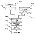
- FIG. 13 is a flowchart showing an operation of storing the cooled sample from the storage to the charged particle beam apparatus according to the present embodiment.
- the sample is subjected to processing such as freeze-drying to produce a cooled sample (S1301), and stored in the sample storage unit 108 in the cryostation main body 101 in a frozen state (S1302).
- the sample holder 107 is inserted from the insertion port 103 and cooled to the target temperature while checking the temperature of the sample stage portion on which the sample is mounted (S1303, S1304).
- the frozen sample 113 is moved to the sample holder 107 by the above-described method and mounted on the sample stage (S1305).
- FIG. 14 is a configuration example of the sample holder according to the embodiment of the present invention, and shows a case where the shutter is not used and a time when the shutter is used.
- the sample holder 107 includes a sample holder main body 1071, a shutter member 1072, a sample stage 1703, a tip shield 1074, and a tip shield presser 1075.
- a sample 113 is mounted on the sample stage 1073.
- the sample holder 107 is arranged in the cryostation system main body 101 and the sample is being transported, the sample 113 is exposed without using the shutter member 1072 as shown in the above figure. .
- the shutter member 1072 is pulled out to the tip shield 1074 as shown in the following figure so that the sample 113 is increased. In this way, the sample 113 taken out from the cryostation system is not exposed to the atmosphere while the sample 113 is being transported to the sample stage of the charged particle beam apparatus. And generation of frost-like substances can be prevented.
- the sample holder 107 is taken out from the insertion port 103 and transported to a target charged particle beam apparatus such as an electron microscope (S1307).
- a target charged particle beam apparatus such as an electron microscope (S1307).
- the sample After introducing the sample holder 107 into the charged particle beam apparatus, the sample is processed and observed (S1308).
- Operation window 125 ... Exhaust port opening / closing part 126 ... Second cooling solvent 127 ... First space 128 ...
- the partition member 129 ... internal wall 130 ... second space 131 ... vacuum space 132 ... outer wall 133 ... knob 134 ... stepped 135a, b ... opening (cover portion) 136... Opening (exhaust port opening / closing part side) 137 ...
- Sample holder 1071 ... Sample holder body 1072 ... Shutter member 1073 ... Sample stand 1074 ... Tip shield 1075 ... Tip shield holder
Landscapes
- Engineering & Computer Science (AREA)
- Chemical & Material Sciences (AREA)
- Physics & Mathematics (AREA)
- Health & Medical Sciences (AREA)
- Combustion & Propulsion (AREA)
- General Engineering & Computer Science (AREA)
- Thermal Sciences (AREA)
- Mechanical Engineering (AREA)
- Analytical Chemistry (AREA)
- Clinical Laboratory Science (AREA)
- Chemical Kinetics & Catalysis (AREA)
- Immunology (AREA)
- Pathology (AREA)
- General Physics & Mathematics (AREA)
- General Health & Medical Sciences (AREA)
- Biochemistry (AREA)
- Life Sciences & Earth Sciences (AREA)
- Sampling And Sample Adjustment (AREA)
Abstract
Description
操作窓124は操作窓取っ手123を有する。排気口開閉部125は、一部に排気口となる段差(あるいは孔)を形成しており、後述するようにつまみ133を移動させることで排気口の開閉が可能である。
クライオステーションシステム本体部101内に試料ホールダ107を配置し、試料の搬送作業を行っている際には、上図に示されるようにシャッター部材1072を使用せずに試料113が露出した状態とする。
一方、試料113を試料台へ搭載後、試料ホールダ107を大気中にさらしている時には、下図に示されるようにシャッター部材1072を先端シールド1074まで引き出して試料113を多くようにする。このようにすることで、クライオステーションシステムから取り出した試料113を、荷電粒子線装置の試料ステージまで搬送している間、試料は大気中にさらされることがないので、真空状態を維持でき、結露や霜状物質の発生を防ぐことができる。
102・・・ふた部
103・・・挿入口
104・・・接続部
105・・・温度調整ユニット
106・・・ケーブル
107・・・試料ホールダ
108・・・試料保存部
109・・・試料保存部スタンド
110・・・温度センサ
111・・・本体部加熱部
112・・・真空封止用ホールダ
113・・・試料
114・・・ピンセット
115a、b・・・試料搬送機構
116・・・試料ホールダ加熱部
117・・・排気機構
118・・・冷却試料の作製
119・・・クライオステーションにて冷却保存
120・・・冷却溶媒
121・・・排気口
122・・・ふた部取っ手
123・・・操作窓取っ手
124・・・操作窓
125・・・排気口開閉部
126・・・第2の冷却溶媒
127・・・第1の空間
128・・・仕切り部材
129・・・内壁
130・・・第2の空間
131・・・真空空間
132・・・外壁
133・・・つまみ
134・・・段差
135a、b・・・開口部(ふた部側)
136・・・開口部(排気口開閉部側)
137・・・試料保持部
1071・・・試料ホールダ本体部
1072・・・シャッター部材
1073・・・試料台
1074・・・先端シールド
1075・・・先端シールド押さえ
Claims (11)
- 試料を冷却状態で保存するクライオステーションシステムであって、
試料を保存する本体部と、
前記本体部上に載置されるふた部と、を備え、
前記本体部は、仕切り部材によって、第1の空間と、第2の空間とに分けられ、
前記第1の空間には、前記試料を冷却する冷却媒体が収容され、
前記第2の空間には、当該第1の空間に収容された冷却媒体を加熱する加熱部が配置され、
前記ふた部は、当該冷却媒体の加熱により発生するガスを外部に排出する排出口を形成することを特徴とするクライオステーションシステム。 - 請求項1に記載されたクライオステーションシステムであって、
前記ふた部は、前記本体部に載置される面の一部に段差を設けることにより前記排出口を形成することを特徴とするクライオステーションシステム。 - 請求項1に記載されたクライオステーションシステムであって、
前記加熱部は、前記第2の空間であって、前記仕切り部材の一端側周辺に配置されることを特徴とするクライオステーションシステム。 - 請求項3に記載されたクライオステーションシステムであって、
前記試料は、前記第1の空間であって、前記仕切り部材の他端側周辺に配置されることを特徴とするクライオステーションシステム。 - 請求項3に記載されたクライオステーションシステムであって、
前記ふた部は、当該本体部に設けられた加熱部の上部に相当する位置に前記排出口を形成することを特徴とするクライオステーションシステム。 - 請求項1に記載されたクライオステーションシステムであって、
前記本体部は、荷電粒子線装置に導入するための試料ホールダを外部から挿入可能な挿入口を有することを特徴とするクライオステーションシステム。 - 請求項6に記載されたクライオステーションシステムであって、
前記本体部は、当該挿入口より挿入された試料ホールダに前記試料を搬送する試料搬送機構を有することを特徴とするクライオステーションシステム。 - 請求項7に記載されたクライオステーションシステムであって、
前記試料搬送機構は、前記試料を回転および昇降させる軸状部材であることを特徴とするクライオステーションシステム。 - 請求項6に記載されたクライオステーションシステムであって、
前記本体部の内部であって前記挿入口の周辺部に、当該挿入口より挿入された試料ホールダを加熱する試料ホールダ加熱部を有することを特徴とするクライオステーションシステム。 - 請求項1に記載されたクライオステーションシステムであって、
前記本体部の内部に排気機構を設け、
前記排気機構は、当該冷却媒体の加熱により発生するガスを前記排出口より排出させるように送風することを特徴とするクライオステーションシステム。 - 請求項1に記載されたクライオステーションシステムであって、
前記本体部は、前記試料を収容する試料保存部を有し、
前記試料保存部は試料保存部用冷却媒体を収容し、
前記試料保存部用冷却媒体は、前記冷却媒体よりも沸点が高いことを特徴とするクライオステーションシステム。
Priority Applications (4)
| Application Number | Priority Date | Filing Date | Title |
|---|---|---|---|
| DE112015001149.8T DE112015001149B4 (de) | 2014-04-03 | 2015-04-02 | Kryostationssystem |
| US15/129,990 US10658150B2 (en) | 2014-04-03 | 2015-04-02 | Cryostation system |
| CN201580014843.XA CN106104250B (zh) | 2014-04-03 | 2015-04-02 | 低温存储系统 |
| JP2016512005A JP6312811B2 (ja) | 2014-04-03 | 2015-04-02 | クライオステーションシステム |
Applications Claiming Priority (2)
| Application Number | Priority Date | Filing Date | Title |
|---|---|---|---|
| JP2014076620 | 2014-04-03 | ||
| JP2014-076620 | 2014-04-03 |
Publications (1)
| Publication Number | Publication Date |
|---|---|
| WO2015152385A1 true WO2015152385A1 (ja) | 2015-10-08 |
Family
ID=54240693
Family Applications (1)
| Application Number | Title | Priority Date | Filing Date |
|---|---|---|---|
| PCT/JP2015/060525 WO2015152385A1 (ja) | 2014-04-03 | 2015-04-02 | クライオステーションシステム |
Country Status (5)
| Country | Link |
|---|---|
| US (1) | US10658150B2 (ja) |
| JP (1) | JP6312811B2 (ja) |
| CN (1) | CN106104250B (ja) |
| DE (1) | DE112015001149B4 (ja) |
| WO (1) | WO2015152385A1 (ja) |
Cited By (1)
| Publication number | Priority date | Publication date | Assignee | Title |
|---|---|---|---|---|
| JP2021057172A (ja) * | 2019-09-30 | 2021-04-08 | 日本電子株式会社 | 試料取付装置 |
Families Citing this family (4)
| Publication number | Priority date | Publication date | Assignee | Title |
|---|---|---|---|---|
| CN106828268B (zh) * | 2016-12-22 | 2018-09-21 | 重庆迪科机电设备有限公司 | 一种车载冷藏箱 |
| CN108801732B (zh) * | 2018-06-15 | 2021-01-12 | 李建锋 | 一种低温样品碾碎装置 |
| EP3627138A1 (en) * | 2018-09-18 | 2020-03-25 | European Molecular Biology Laboratory | Sample thickness measuring arrangement and method for measuring a thickness of a sample at cryogenic temperature by interferometry using a cryostat |
| LU102232B1 (en) * | 2020-11-25 | 2022-05-30 | Luxembourg Inst Science & Tech List | Thermal management system |
Citations (4)
| Publication number | Priority date | Publication date | Assignee | Title |
|---|---|---|---|---|
| JPS6140538A (ja) * | 1984-07-12 | 1986-02-26 | ツエー・ライヘルト・オプティッシェ・ヴェルケ・アーゲー | 低温で生物学的標本を処理するための装置 |
| JPS63143478A (ja) * | 1986-12-08 | 1988-06-15 | 住友電気工業株式会社 | クライオスタツト |
| JPH1163761A (ja) * | 1997-08-19 | 1999-03-05 | Tomoegawa Paper Co Ltd | 簡易冷却装置及び該装置を用いた切削方法 |
| JP2010008141A (ja) * | 2008-06-25 | 2010-01-14 | Canon Inc | 固体試料の作製装置、固体試料の作製方法及び試料の観察方法 |
Family Cites Families (15)
| Publication number | Priority date | Publication date | Assignee | Title |
|---|---|---|---|---|
| DE2944806A1 (de) | 1979-11-06 | 1981-05-14 | C. Reichert Optische Werke Ag, Wien | Einrichtung zur metallspiegel-kryofixation sowie zur nachfolgenden kryopraeparation biologischer objekte |
| DE3430471C1 (de) * | 1984-08-18 | 1986-01-30 | C. Reichert Optische Werke Ag, Wien | Vorrichtung zur Entnahme von fluessigem Stickstoff aus einer Einrichtung zur Kryofixation und/oder Kryopraeparation zum Zwecke des Kryotransfers gefrorener Proben |
| US4888956A (en) | 1987-01-16 | 1989-12-26 | Roux Murray Pieter W Le | Cryogenic apparatus and cryogenic methods |
| US4739622A (en) * | 1987-07-27 | 1988-04-26 | Cryogenics International, Inc. | Apparatus and method for the deep cryogenic treatment of materials |
| CN2032598U (zh) | 1987-09-14 | 1989-02-15 | 叶常竹 | 生物活体自动植冰冷冻器 |
| US5779089A (en) * | 1996-07-26 | 1998-07-14 | Forma Scientific, Inc. | Cryogenic storage apparatus with lid vent |
| US5753924A (en) * | 1997-03-12 | 1998-05-19 | Gatan, Inc. | Ultra-high tilt specimen cryotransfer holder for electron microscope |
| CN2550699Y (zh) | 2002-02-19 | 2003-05-14 | 王德和 | 冷凝设备的改良 |
| JP5028142B2 (ja) | 2007-05-17 | 2012-09-19 | キヤノンアネルバ株式会社 | クライオトラップ |
| CN201321475Y (zh) | 2008-12-30 | 2009-10-07 | 东方电气集团东方汽轮机有限公司 | 工件液氮熏套冷却装置 |
| JP5250470B2 (ja) * | 2009-04-22 | 2013-07-31 | 株式会社日立ハイテクノロジーズ | 試料ホールダ,該試料ホールダの使用法、及び荷電粒子装置 |
| AT508018B1 (de) | 2009-07-29 | 2010-10-15 | Leica Mikrosysteme Gmbh | Kryopräparationskammer zum manipulieren einer probe für die elektronenmikroskopie |
| JP5260575B2 (ja) * | 2010-02-24 | 2013-08-14 | 株式会社日立ハイテクノロジーズ | 電子顕微鏡、および試料ホルダ |
| JP6192889B2 (ja) | 2011-10-19 | 2017-09-06 | 株式会社明治 | 透過型電子顕微鏡用試料の調製方法 |
| JP5732006B2 (ja) | 2012-06-28 | 2015-06-10 | 株式会社日立ハイテクノロジーズ | 試料冷却ホルダー及び冷却源容器 |
-
2015
- 2015-04-02 JP JP2016512005A patent/JP6312811B2/ja active Active
- 2015-04-02 WO PCT/JP2015/060525 patent/WO2015152385A1/ja active Application Filing
- 2015-04-02 DE DE112015001149.8T patent/DE112015001149B4/de active Active
- 2015-04-02 US US15/129,990 patent/US10658150B2/en not_active Expired - Fee Related
- 2015-04-02 CN CN201580014843.XA patent/CN106104250B/zh active Active
Patent Citations (4)
| Publication number | Priority date | Publication date | Assignee | Title |
|---|---|---|---|---|
| JPS6140538A (ja) * | 1984-07-12 | 1986-02-26 | ツエー・ライヘルト・オプティッシェ・ヴェルケ・アーゲー | 低温で生物学的標本を処理するための装置 |
| JPS63143478A (ja) * | 1986-12-08 | 1988-06-15 | 住友電気工業株式会社 | クライオスタツト |
| JPH1163761A (ja) * | 1997-08-19 | 1999-03-05 | Tomoegawa Paper Co Ltd | 簡易冷却装置及び該装置を用いた切削方法 |
| JP2010008141A (ja) * | 2008-06-25 | 2010-01-14 | Canon Inc | 固体試料の作製装置、固体試料の作製方法及び試料の観察方法 |
Cited By (2)
| Publication number | Priority date | Publication date | Assignee | Title |
|---|---|---|---|---|
| JP2021057172A (ja) * | 2019-09-30 | 2021-04-08 | 日本電子株式会社 | 試料取付装置 |
| JP6995099B2 (ja) | 2019-09-30 | 2022-01-14 | 日本電子株式会社 | 試料取付装置 |
Also Published As
| Publication number | Publication date |
|---|---|
| US10658150B2 (en) | 2020-05-19 |
| JP6312811B2 (ja) | 2018-04-18 |
| JPWO2015152385A1 (ja) | 2017-04-13 |
| CN106104250A (zh) | 2016-11-09 |
| CN106104250B (zh) | 2019-12-13 |
| DE112015001149B4 (de) | 2023-09-28 |
| US20170213693A1 (en) | 2017-07-27 |
| DE112015001149T5 (de) | 2016-11-24 |
Similar Documents
| Publication | Publication Date | Title |
|---|---|---|
| JP6312811B2 (ja) | クライオステーションシステム | |
| Stephenson et al. | The Laplace Project: An integrated suite for preparing and transferring atom probe samples under cryogenic and UHV conditions | |
| JP6336198B2 (ja) | 低温で凍結試料を積み替えるローディングステーション | |
| US20150289500A1 (en) | Cryogenic storage device and method for operating same | |
| US8439216B1 (en) | Telescopic specimen holder | |
| US8516909B2 (en) | Cryopreparation chamber for manipulating a sample for electron microscopy | |
| JP6133070B2 (ja) | 低温保管システム | |
| US20210255076A1 (en) | Sample cell for handling and measuring sensitive samples in low temperature conditions | |
| JP5204592B2 (ja) | 薄膜試料観察システム及び冷却試料ホルダ並びに薄膜試料観察方法 | |
| JP7184601B2 (ja) | 温度サイクル試験装置及びその方法 | |
| US20090138995A1 (en) | Atom probe component treatments | |
| JP2011208811A (ja) | 密閉容器及び乾燥処理装置 | |
| JP2003222574A (ja) | 試料処理装置 | |
| WO2015041267A1 (ja) | アンチコンタミネーショントラップおよび真空応用装置 | |
| US20100162736A1 (en) | Apparatus and method for the preparation of fluid bearing materials for surface analysis in a vacuum | |
| JP2017050181A (ja) | 搬送装置、処理装置、真空装置および荷電粒子ビーム装置 | |
| US20230073506A1 (en) | Workstation, preparation station and method for manipulating an electron microscopy grid assembly | |
| JP3535396B2 (ja) | 試料分析観察装置 | |
| JP4083998B2 (ja) | 真空カメラ | |
| JP2007108149A (ja) | 試料搬送・分析キット | |
| JP2016143528A (ja) | 試料搬送機構及び真空装置 | |
| US11808679B2 (en) | Method and apparatus for cryogenic and environmental controlled specimen handling | |
| JPH0698294B2 (ja) | 輸送容器装置 | |
| JP2024524505A (ja) | サンプル移送装置を分析装置又はサンプル調製装置に相互接続する装置、及び環境制御条件下でサンプルを輸送するコンテナー | |
| JP2619731B2 (ja) | 脱離ガスの検出装置および方法 |
Legal Events
| Date | Code | Title | Description |
|---|---|---|---|
| 121 | Ep: the epo has been informed by wipo that ep was designated in this application |
Ref document number: 15773740 Country of ref document: EP Kind code of ref document: A1 |
|
| ENP | Entry into the national phase |
Ref document number: 2016512005 Country of ref document: JP Kind code of ref document: A |
|
| WWE | Wipo information: entry into national phase |
Ref document number: 15129990 Country of ref document: US |
|
| WWE | Wipo information: entry into national phase |
Ref document number: 112015001149 Country of ref document: DE |
|
| 122 | Ep: pct application non-entry in european phase |
Ref document number: 15773740 Country of ref document: EP Kind code of ref document: A1 |