WO2015152303A1 - Revêtement de tuyau - Google Patents
Revêtement de tuyau Download PDFInfo
- Publication number
- WO2015152303A1 WO2015152303A1 PCT/JP2015/060271 JP2015060271W WO2015152303A1 WO 2015152303 A1 WO2015152303 A1 WO 2015152303A1 JP 2015060271 W JP2015060271 W JP 2015060271W WO 2015152303 A1 WO2015152303 A1 WO 2015152303A1
- Authority
- WO
- WIPO (PCT)
- Prior art keywords
- pipe
- main body
- axial direction
- split
- tube cover
- Prior art date
Links
Images


Classifications
-
- F—MECHANICAL ENGINEERING; LIGHTING; HEATING; WEAPONS; BLASTING
- F01—MACHINES OR ENGINES IN GENERAL; ENGINE PLANTS IN GENERAL; STEAM ENGINES
- F01N—GAS-FLOW SILENCERS OR EXHAUST APPARATUS FOR MACHINES OR ENGINES IN GENERAL; GAS-FLOW SILENCERS OR EXHAUST APPARATUS FOR INTERNAL COMBUSTION ENGINES
- F01N13/00—Exhaust or silencing apparatus characterised by constructional features ; Exhaust or silencing apparatus, or parts thereof, having pertinent characteristics not provided for in, or of interest apart from, groups F01N1/00 - F01N5/00, F01N9/00, F01N11/00
- F01N13/08—Other arrangements or adaptations of exhaust conduits
-
- F—MECHANICAL ENGINEERING; LIGHTING; HEATING; WEAPONS; BLASTING
- F01—MACHINES OR ENGINES IN GENERAL; ENGINE PLANTS IN GENERAL; STEAM ENGINES
- F01N—GAS-FLOW SILENCERS OR EXHAUST APPARATUS FOR MACHINES OR ENGINES IN GENERAL; GAS-FLOW SILENCERS OR EXHAUST APPARATUS FOR INTERNAL COMBUSTION ENGINES
- F01N13/00—Exhaust or silencing apparatus characterised by constructional features ; Exhaust or silencing apparatus, or parts thereof, having pertinent characteristics not provided for in, or of interest apart from, groups F01N1/00 - F01N5/00, F01N9/00, F01N11/00
- F01N13/14—Exhaust or silencing apparatus characterised by constructional features ; Exhaust or silencing apparatus, or parts thereof, having pertinent characteristics not provided for in, or of interest apart from, groups F01N1/00 - F01N5/00, F01N9/00, F01N11/00 having thermal insulation
-
- F—MECHANICAL ENGINEERING; LIGHTING; HEATING; WEAPONS; BLASTING
- F16—ENGINEERING ELEMENTS AND UNITS; GENERAL MEASURES FOR PRODUCING AND MAINTAINING EFFECTIVE FUNCTIONING OF MACHINES OR INSTALLATIONS; THERMAL INSULATION IN GENERAL
- F16L—PIPES; JOINTS OR FITTINGS FOR PIPES; SUPPORTS FOR PIPES, CABLES OR PROTECTIVE TUBING; MEANS FOR THERMAL INSULATION IN GENERAL
- F16L59/00—Thermal insulation in general
- F16L59/14—Arrangements for the insulation of pipes or pipe systems
- F16L59/16—Arrangements specially adapted to local requirements at flanges, junctions, valves or the like
- F16L59/18—Arrangements specially adapted to local requirements at flanges, junctions, valves or the like adapted for joints
- F16L59/182—Joints with sleeve or socket
-
- F—MECHANICAL ENGINEERING; LIGHTING; HEATING; WEAPONS; BLASTING
- F01—MACHINES OR ENGINES IN GENERAL; ENGINE PLANTS IN GENERAL; STEAM ENGINES
- F01N—GAS-FLOW SILENCERS OR EXHAUST APPARATUS FOR MACHINES OR ENGINES IN GENERAL; GAS-FLOW SILENCERS OR EXHAUST APPARATUS FOR INTERNAL COMBUSTION ENGINES
- F01N2310/00—Selection of sound absorbing or insulating material
- F01N2310/02—Mineral wool, e.g. glass wool, rock wool, asbestos or the like
-
- F—MECHANICAL ENGINEERING; LIGHTING; HEATING; WEAPONS; BLASTING
- F01—MACHINES OR ENGINES IN GENERAL; ENGINE PLANTS IN GENERAL; STEAM ENGINES
- F01N—GAS-FLOW SILENCERS OR EXHAUST APPARATUS FOR MACHINES OR ENGINES IN GENERAL; GAS-FLOW SILENCERS OR EXHAUST APPARATUS FOR INTERNAL COMBUSTION ENGINES
- F01N2450/00—Methods or apparatus for fitting, inserting or repairing different elements
- F01N2450/28—Methods or apparatus for fitting, inserting or repairing different elements by using adhesive material, e.g. cement
-
- F—MECHANICAL ENGINEERING; LIGHTING; HEATING; WEAPONS; BLASTING
- F01—MACHINES OR ENGINES IN GENERAL; ENGINE PLANTS IN GENERAL; STEAM ENGINES
- F01N—GAS-FLOW SILENCERS OR EXHAUST APPARATUS FOR MACHINES OR ENGINES IN GENERAL; GAS-FLOW SILENCERS OR EXHAUST APPARATUS FOR INTERNAL COMBUSTION ENGINES
- F01N2530/00—Selection of materials for tubes, chambers or housings
- F01N2530/02—Corrosion resistive metals
- F01N2530/04—Steel alloys, e.g. stainless steel
-
- F—MECHANICAL ENGINEERING; LIGHTING; HEATING; WEAPONS; BLASTING
- F16—ENGINEERING ELEMENTS AND UNITS; GENERAL MEASURES FOR PRODUCING AND MAINTAINING EFFECTIVE FUNCTIONING OF MACHINES OR INSTALLATIONS; THERMAL INSULATION IN GENERAL
- F16L—PIPES; JOINTS OR FITTINGS FOR PIPES; SUPPORTS FOR PIPES, CABLES OR PROTECTIVE TUBING; MEANS FOR THERMAL INSULATION IN GENERAL
- F16L59/00—Thermal insulation in general
- F16L59/10—Bandages or covers for the protection of the insulation, e.g. against the influence of the environment or against mechanical damage
Definitions
- the present invention relates to an exhaust pipe and a pipe cover for other pipes.
- a high-performance internal combustion engine such as a V-type engine may be used.
- a high-performance internal combustion engine is often mounted on a vehicle such that the crankshaft shaft is transverse to the traveling direction of the vehicle (so-called horizontal placement).
- the pistons are arranged before and after the crankshaft shaft. It is done.
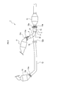
- the exhaust device 1 is formed in a shape that takes in exhaust gas from before and after the internal combustion engine.
- exhaust manifolds having first catalysts 10 and 11 are attached to the front and rear of the internal combustion engine.
- a Y-shaped exhaust merging pipe 3 for merging the exhaust gases sent from the first catalysts 10 and 11 is attached to the rear of the rear first catalyst 11, and further to the rear of the exhaust merging pipe 3.
- the second catalyst 13 is installed.
- the exhaust merging pipe 3 is attached to the rear side of the first catalyst 11 on the rear side, but is separated from the first catalyst 10 on the front side. Therefore, the exhaust merging pipe 3 and the first catalyst 11 are connected to the exhaust merging pipe. 3 is connected through a long exhaust pipe 12 extending from 3.
- the lengths of the exhaust paths from the first catalysts 10 and 11 to the second catalyst 13 are different.
- the exhaust pipes 3 and 12 having the exhaust paths having different lengths are called unequal length exhaust pipes.
- the upstream bifurcated part and the downstream part are called branches.
- the branch connected to the first catalyst 11 is the first branch 31
- the branch connected to the exhaust pipe 12 is the second branch 32
- the downstream branch is the third branch. It is called part 33.
- the first heat insulator 4 is attached to the first branch portion 31 connected to the first catalyst 11 among the first branch portion 31, the second branch portion 32, and the third branch portion 33 constituting the exhaust gas merging pipe 3.
- the second heat retaining device 5 is attached to the third branch portion 33 connected to the second catalyst 13.
- the first heat insulator 4 includes a tube cover 6 formed in a substantially cylindrical shape, and a heat insulating material 41 packed between the inner wall surface of the tube cover 6 and the outer wall surface of the first branch portion 31.
- the second heat retaining device 5 includes a tube cover 50 formed in a substantially cylindrical shape, and a heat insulating material 51 packed between the inner wall surface of the tube cover 50 and the outer wall surface of the third branch portion 33.
- the tube covers 6 and 50 are made of a stainless steel heat shield, and the heat insulating materials 41 and 51 are made of glass wool. (Patent Document 1)
- the first branch portion 31 is formed in a shape that is obtained by bending a straight pipe into an obtuse angle.
- the first branch portion 31 has a portion from the bending point 31c to the junction point of the second branch portion 32 and the third branch portion 33 (hereinafter referred to as the first portion 31a), and forward from the junction point.
- a portion extending in a straight line toward the front side of the bending point 31c (hereinafter referred to as a second portion 31b) is disposed so as to extend obliquely forward and upward from the bending point 31c.
- the downstream side (the merging side with the second branch portion 32) of the portion to which the tube cover 6 constituting the first heat insulator 4 is attached since the pipe is bent, the cross-sectional shape may vary in the vicinity of the bent portion due to the difference in material lot (for example, an elliptical shape).
- a gap is formed between the edge of the tube port located on the downstream side of the tube cover 6 and the outer peripheral surface of the first branch portion 31, and the gap This part may become unwelded during welding, and the tube cover 6 may not be able to sufficiently suppress the heat radiation from the first branch portion 31.
- the tube cover 6 may be difficult to fix the tube cover 6 to the first branch portion 31 by welding. It was.
- the tube cover of one aspect of the present invention is A main body that is formed in a cylindrical shape and has a split that is split along the axial direction; Abutting portions that are located on one end side in the axial direction and are attached to the pipe, and on both sides of the split, It is located on the other end side in the axial direction, and when attached to the pipe, one side of the both sides of the split is superposed on the other side.
- This tube cover is attached so that the tube port located on the other end side in the axial direction faces the side where the pipe is bent. Then, even if the cross-sectional shape of the pipe varies due to bending, this pipe cover can be squeezed on the other end side in the axial direction by the overlapping portion, so the edge of the tube port located on the other end side in the axial direction and the outer periphery of the pipe It can be attached to the piping without causing a gap between the surface. Therefore, when this pipe cover is used, the pipe cover can be firmly fixed to the pipe by welding.
- the main body of the tube cover is formed of a hard material, if such a movement space is formed, the diameter can be smoothly reduced.
- the movement space will become easy to generate
- a hole covering portion that extends from the other end in the axial direction, and covers a hole formed on the other end side in the axial direction by overlapping may be provided. If it does in this way, since a hole covering part closes the hole formed in the other end side of an axial direction by superposition, it can control that a hole is opened from the inside of a main part and heat is radiated.
- the overlapping portion overlaps one side of both sides of the split with the other side, the other side moves below the one side of both sides of the split in the direction of reducing the diameter of the main body.
- the hole is formed by the moving space.
- FIG. 4A is a plan view of the tube cover.
- FIG. 4B is an enlarged view of a portion surrounded by reference numeral VB in FIG. 4A, and a part of the configuration is shown in a transparent view with a one-dot chain line indicating the upper side portion 60 t and a dotted line indicating the lower side portion 60 u.
- FIG. 5A is a view of the width portion indicated by the symbol A in FIG. 4B with respect to the upper portion 60t, as viewed from the direction of the arrow VA.
- FIG. 5B is a VB-VB cross-sectional view of FIG. 4B.
- FIG. 5C is a sectional view taken along the line VC-VC of FIG. 4B.
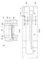
- FIG. 6A is a front view of the tube cover.
- 6B is a cross-sectional view taken along the line VIB-VIB of FIG. 6A.
- 6C is a VIC-VIC cross-sectional view of FIG. 6A.
- FIG. 7A is a cross-sectional view taken along the line VIB-VIB in FIG. 6A and shows a state where no aperture is applied.
- FIG. 7B is a cross-sectional view taken along the line VIB-VIB in FIG. 6A and shows a state when a diaphragm is being applied.
- symbol of structures other than the tube cover 6 is used if necessary.
- “6” is used as a symbol indicating the tube cover, but this does not indicate the same configuration as the tube cover described in the background art. This is to clarify which part of the background art has caused the present invention by using a problem as a hint. However, this does not prevent the tube cover 6 of this embodiment from being used as a cover for other parts such as the tube cover 50 described in the background art.
- the tube cover 6 of the present embodiment includes a main body 60 that is formed in a cylindrical shape and has a split 6 a that is cracked along the axial direction. Also, the main body 60 is formed such that both end portions in the axial direction (portions having a predetermined width from both end portions in the axial direction of the main body 60) 60a and 60b are gradually reduced in diameter toward the respective end portions. Yes.
- both sides of the split 6a are brought together.
- this associated portion is referred to as a butt portion 61.
- the other end side ⁇ in the axial direction of the main body is attached to the pipe 9, one side of both sides of the split 6a is overlapped with the other side.
- the overlapped portion is referred to as a superposition portion 62.
- the main body 60 is formed in a shape in which the overlapping portion 62 is extended in the axial direction, and has a hole covering portion 63 that extends outward from the edge portion 60c on the other end side ⁇ of the main body 60. ing. Next, details such as the shapes of the abutting portion 61 and the overlapping portion 62 will be described.
- both side portions sandwiching the split 6a of the main body 60 are referred to as an upper portion 60t and a lower portion 60u.
- the shape of the portion corresponding to the abutment portion 61 in the upper portion 60t and the portion facing the lower portion 60u will be described with reference to FIG. 5A.
- the portion corresponding to the abutting portion 61 of the upper portion 60t has a portion 61a that swells for a while as it goes from the one end side ⁇ in the axial direction of the main body 60 to the other end ⁇ in the vicinity of the overlapping portion 62,
- the portion 61b closer to the overlapping portion 62 than the portion 61a that swells for a while is formed with a thickness that maintains the bulge.
- the other portion 61c of the abutting portion 61 is formed with a half thickness of the portion 61b that maintains the bulge.
- the portion corresponding to the abutting portion 61 in the upper side portion 60t is abutted with the portion corresponding to the abutting portion 61 in the lower side portion 60u, but the lower side portion 60u.
- the portion corresponding to the abutting portion 61 has the same thickness as the other portion 61c of the upper portion 60t throughout.
- the portions 61a and 61b other than the other portion 61c of the upper portion 60t are butted against the lower portion of the portions 61a and 61b, as indicated by hatching in FIG. 5A.
- the portion of the upper portion 60t corresponding to the overlapping portion 62 is formed with the same thickness as a whole when viewed in the direction of arrow E1 (see FIG. 4B) as shown in FIG. 5B.
- a stepped portion 62a is formed that rises upward for a while and rises one step with respect to the other portion 62c.
- the portion (step maintaining portion 62b) closer to the split 6a than the step portion 62a maintains a state where the step portion 62a is one step higher than the other portions.
- the portion corresponding to the abutting portion 61 in the upper portion 60t is in the vicinity of the split 6a and upward as it approaches the split 6a as shown in the direction of the arrow E2 (see FIG. 4B) as shown in FIG. 5C.
- the portion 61e closer to the split 6a than the portion 61d that swells for a while is formed with a thickness that maintains the bulge.
- the other portion 61f is formed with a half thickness of the portion 61e that maintains the bulge.
- the abutting portion 61 is abutted with the portions forming the thickness of the lower side portion 60 u and the upper side portion 60 t, but the overlapping portion 62 is a stepped portion.
- a moving space 8 is formed below the portion of the step maintaining portion 62b between the step portion 62a and the split 6a, and the tip of the step maintaining portion 62b is Overlaid on the side 60u.
- the moving space 8 is formed from a boundary portion between the abutting portion 61 and the overlapping portion 62 to an edge portion 60c on the other end side ⁇ of the main body 60.
- a hole 8 a is formed on the other end side ⁇ in the axial direction of the main body 60 by overlapping.
- the hole covering portion 63 covers and conceals the hole portion 8a from the outside. Further, since the tube cover 6 is formed with the moving space 8, when the main body 60 is squeezed in the circumferential direction, as shown in FIG. 7B, the lower side portion 60u can move in the moving space 8, Can be squeezed.
- the main body 60 of the tube cover 6 is formed of a hard material, the diameter can be reduced smoothly by forming the moving space 8.
- the hole cover 63 closes the hole 8a generated by forming the moving space 8. Therefore, it is possible to prevent heat from being radiated from the inside of the main body 60 through the hole 8a.
Abstract
L'invention porte sur un revêtement de tuyau qui comprend : un corps principal formé sous une forme tubulaire, et ayant une fente de fissure le long de la direction axiale ; une section en butée positionnée à une extrémité dans la direction axiale du corps principal, et au niveau de laquelle les deux côtés de la fissure du corps principal butent pendant l'installation sur une tubulure ; une section de chevauchement positionnée à l'autre extrémité dans la direction axiale du corps principal, et au niveau de laquelle l'un des deux côtés de la fissure du corps principal chevauche l'autre côté pendant l'installation sur la tubulure.
Priority Applications (1)
| Application Number | Priority Date | Filing Date | Title |
|---|---|---|---|
| JP2016511967A JPWO2015152303A1 (ja) | 2014-03-31 | 2015-03-31 | 管カバー |
Applications Claiming Priority (2)
| Application Number | Priority Date | Filing Date | Title |
|---|---|---|---|
| JP2014-072442 | 2014-03-31 | ||
| JP2014072442 | 2014-03-31 |
Publications (1)
| Publication Number | Publication Date |
|---|---|
| WO2015152303A1 true WO2015152303A1 (fr) | 2015-10-08 |
Family
ID=54240621
Family Applications (1)
| Application Number | Title | Priority Date | Filing Date |
|---|---|---|---|
| PCT/JP2015/060271 WO2015152303A1 (fr) | 2014-03-31 | 2015-03-31 | Revêtement de tuyau |
Country Status (2)
| Country | Link |
|---|---|
| JP (1) | JPWO2015152303A1 (fr) |
| WO (1) | WO2015152303A1 (fr) |
Citations (4)
| Publication number | Priority date | Publication date | Assignee | Title |
|---|---|---|---|---|
| US3588965A (en) * | 1966-04-06 | 1971-06-29 | Ultronix Inc | Insulated pipeline jacketing systems |
| DE2928165A1 (de) * | 1979-07-12 | 1981-01-29 | Steffens & Co | Vorgeformte leitungsisolation |
| JPH0477094U (fr) * | 1990-11-19 | 1992-07-06 | ||
| JPH10508938A (ja) * | 1995-05-19 | 1998-09-02 | サン−ゴバン インダストリアル セラミックス,インコーポレイティド | 過熱管の新規な耐熱遮蔽構造 |
Family Cites Families (1)
| Publication number | Priority date | Publication date | Assignee | Title |
|---|---|---|---|---|
| JP5697064B2 (ja) * | 2012-08-27 | 2015-04-08 | 古河As株式会社 | 電磁シールド管 |
-
2015
- 2015-03-31 WO PCT/JP2015/060271 patent/WO2015152303A1/fr active Application Filing
- 2015-03-31 JP JP2016511967A patent/JPWO2015152303A1/ja active Pending
Patent Citations (4)
| Publication number | Priority date | Publication date | Assignee | Title |
|---|---|---|---|---|
| US3588965A (en) * | 1966-04-06 | 1971-06-29 | Ultronix Inc | Insulated pipeline jacketing systems |
| DE2928165A1 (de) * | 1979-07-12 | 1981-01-29 | Steffens & Co | Vorgeformte leitungsisolation |
| JPH0477094U (fr) * | 1990-11-19 | 1992-07-06 | ||
| JPH10508938A (ja) * | 1995-05-19 | 1998-09-02 | サン−ゴバン インダストリアル セラミックス,インコーポレイティド | 過熱管の新規な耐熱遮蔽構造 |
Also Published As
| Publication number | Publication date |
|---|---|
| JPWO2015152303A1 (ja) | 2017-04-13 |
Similar Documents
| Publication | Publication Date | Title |
|---|---|---|
| US10570779B2 (en) | Turbine housing | |
| JP4624459B2 (ja) | 排気マニホールド | |
| JP6114244B2 (ja) | 車両の排気装置 | |
| WO2015152303A1 (fr) | Revêtement de tuyau | |
| JP2010127097A (ja) | 排気マニホールド | |
| JP5829995B2 (ja) | 排気系部材 | |
| US8950178B2 (en) | Exhaust device of multi-cylinder engine | |
| JP2007321569A (ja) | 消音器構造 | |
| JP6185501B2 (ja) | ヒートインシュレータ | |
| JP5675327B2 (ja) | 保護管固定構造 | |
| JP2020084776A (ja) | 排気構造 | |
| JP2016056788A (ja) | 車両に搭載される触媒付き排気管 | |
| US20180347440A1 (en) | Exhaust system support structure | |
| JP2013024201A (ja) | 内燃機関の排気装置 | |
| KR101619627B1 (ko) | 촉매장치 유입부의 용접구조 | |
| JP6280209B2 (ja) | 排気合流管の保温構造 | |
| JP2016153607A (ja) | タービンハウジング | |
| CN105156194A (zh) | 一种汽车排气管的装饰尾管 | |
| US20200217237A1 (en) | Heat shield having a sealing element | |
| JP2015045313A (ja) | 車両用マフラー | |
| JP7364549B2 (ja) | 排気管 | |
| JP2010138835A (ja) | 内燃機関の排気マニホールド構造 | |
| JP2016125411A (ja) | 排気管 | |
| JP2022009107A5 (fr) | ||
| JP2016176423A (ja) | ヒートインシュレータ |
Legal Events
| Date | Code | Title | Description |
|---|---|---|---|
| 121 | Ep: the epo has been informed by wipo that ep was designated in this application |
Ref document number: 15773961 Country of ref document: EP Kind code of ref document: A1 |
|
| ENP | Entry into the national phase |
Ref document number: 2016511967 Country of ref document: JP Kind code of ref document: A |
|
| NENP | Non-entry into the national phase | ||
| 122 | Ep: pct application non-entry in european phase |
Ref document number: 15773961 Country of ref document: EP Kind code of ref document: A1 |