WO2015152303A1 - Pipe cover - Google Patents
Pipe cover Download PDFInfo
- Publication number
- WO2015152303A1 WO2015152303A1 PCT/JP2015/060271 JP2015060271W WO2015152303A1 WO 2015152303 A1 WO2015152303 A1 WO 2015152303A1 JP 2015060271 W JP2015060271 W JP 2015060271W WO 2015152303 A1 WO2015152303 A1 WO 2015152303A1
- Authority
- WO
- WIPO (PCT)
- Prior art keywords
- pipe
- main body
- axial direction
- split
- tube cover
- Prior art date
Links
Images


Classifications
-
- F—MECHANICAL ENGINEERING; LIGHTING; HEATING; WEAPONS; BLASTING
- F01—MACHINES OR ENGINES IN GENERAL; ENGINE PLANTS IN GENERAL; STEAM ENGINES
- F01N—GAS-FLOW SILENCERS OR EXHAUST APPARATUS FOR MACHINES OR ENGINES IN GENERAL; GAS-FLOW SILENCERS OR EXHAUST APPARATUS FOR INTERNAL COMBUSTION ENGINES
- F01N13/00—Exhaust or silencing apparatus characterised by constructional features ; Exhaust or silencing apparatus, or parts thereof, having pertinent characteristics not provided for in, or of interest apart from, groups F01N1/00 - F01N5/00, F01N9/00, F01N11/00
- F01N13/08—Other arrangements or adaptations of exhaust conduits
-
- F—MECHANICAL ENGINEERING; LIGHTING; HEATING; WEAPONS; BLASTING
- F01—MACHINES OR ENGINES IN GENERAL; ENGINE PLANTS IN GENERAL; STEAM ENGINES
- F01N—GAS-FLOW SILENCERS OR EXHAUST APPARATUS FOR MACHINES OR ENGINES IN GENERAL; GAS-FLOW SILENCERS OR EXHAUST APPARATUS FOR INTERNAL COMBUSTION ENGINES
- F01N13/00—Exhaust or silencing apparatus characterised by constructional features ; Exhaust or silencing apparatus, or parts thereof, having pertinent characteristics not provided for in, or of interest apart from, groups F01N1/00 - F01N5/00, F01N9/00, F01N11/00
- F01N13/14—Exhaust or silencing apparatus characterised by constructional features ; Exhaust or silencing apparatus, or parts thereof, having pertinent characteristics not provided for in, or of interest apart from, groups F01N1/00 - F01N5/00, F01N9/00, F01N11/00 having thermal insulation
-
- F—MECHANICAL ENGINEERING; LIGHTING; HEATING; WEAPONS; BLASTING
- F16—ENGINEERING ELEMENTS AND UNITS; GENERAL MEASURES FOR PRODUCING AND MAINTAINING EFFECTIVE FUNCTIONING OF MACHINES OR INSTALLATIONS; THERMAL INSULATION IN GENERAL
- F16L—PIPES; JOINTS OR FITTINGS FOR PIPES; SUPPORTS FOR PIPES, CABLES OR PROTECTIVE TUBING; MEANS FOR THERMAL INSULATION IN GENERAL
- F16L59/00—Thermal insulation in general
- F16L59/14—Arrangements for the insulation of pipes or pipe systems
- F16L59/16—Arrangements specially adapted to local requirements at flanges, junctions, valves or the like
- F16L59/18—Arrangements specially adapted to local requirements at flanges, junctions, valves or the like adapted for joints
- F16L59/182—Joints with sleeve or socket
-
- F—MECHANICAL ENGINEERING; LIGHTING; HEATING; WEAPONS; BLASTING
- F01—MACHINES OR ENGINES IN GENERAL; ENGINE PLANTS IN GENERAL; STEAM ENGINES
- F01N—GAS-FLOW SILENCERS OR EXHAUST APPARATUS FOR MACHINES OR ENGINES IN GENERAL; GAS-FLOW SILENCERS OR EXHAUST APPARATUS FOR INTERNAL COMBUSTION ENGINES
- F01N2310/00—Selection of sound absorbing or insulating material
- F01N2310/02—Mineral wool, e.g. glass wool, rock wool, asbestos or the like
-
- F—MECHANICAL ENGINEERING; LIGHTING; HEATING; WEAPONS; BLASTING
- F01—MACHINES OR ENGINES IN GENERAL; ENGINE PLANTS IN GENERAL; STEAM ENGINES
- F01N—GAS-FLOW SILENCERS OR EXHAUST APPARATUS FOR MACHINES OR ENGINES IN GENERAL; GAS-FLOW SILENCERS OR EXHAUST APPARATUS FOR INTERNAL COMBUSTION ENGINES
- F01N2450/00—Methods or apparatus for fitting, inserting or repairing different elements
- F01N2450/28—Methods or apparatus for fitting, inserting or repairing different elements by using adhesive material, e.g. cement
-
- F—MECHANICAL ENGINEERING; LIGHTING; HEATING; WEAPONS; BLASTING
- F01—MACHINES OR ENGINES IN GENERAL; ENGINE PLANTS IN GENERAL; STEAM ENGINES
- F01N—GAS-FLOW SILENCERS OR EXHAUST APPARATUS FOR MACHINES OR ENGINES IN GENERAL; GAS-FLOW SILENCERS OR EXHAUST APPARATUS FOR INTERNAL COMBUSTION ENGINES
- F01N2530/00—Selection of materials for tubes, chambers or housings
- F01N2530/02—Corrosion resistive metals
- F01N2530/04—Steel alloys, e.g. stainless steel
-
- F—MECHANICAL ENGINEERING; LIGHTING; HEATING; WEAPONS; BLASTING
- F16—ENGINEERING ELEMENTS AND UNITS; GENERAL MEASURES FOR PRODUCING AND MAINTAINING EFFECTIVE FUNCTIONING OF MACHINES OR INSTALLATIONS; THERMAL INSULATION IN GENERAL
- F16L—PIPES; JOINTS OR FITTINGS FOR PIPES; SUPPORTS FOR PIPES, CABLES OR PROTECTIVE TUBING; MEANS FOR THERMAL INSULATION IN GENERAL
- F16L59/00—Thermal insulation in general
- F16L59/10—Bandages or covers for the protection of the insulation, e.g. against the influence of the environment or against mechanical damage
Definitions
- the present invention relates to an exhaust pipe and a pipe cover for other pipes.
- a high-performance internal combustion engine such as a V-type engine may be used.
- a high-performance internal combustion engine is often mounted on a vehicle such that the crankshaft shaft is transverse to the traveling direction of the vehicle (so-called horizontal placement).
- the pistons are arranged before and after the crankshaft shaft. It is done.
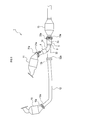
- the exhaust device 1 is formed in a shape that takes in exhaust gas from before and after the internal combustion engine.
- exhaust manifolds having first catalysts 10 and 11 are attached to the front and rear of the internal combustion engine.
- a Y-shaped exhaust merging pipe 3 for merging the exhaust gases sent from the first catalysts 10 and 11 is attached to the rear of the rear first catalyst 11, and further to the rear of the exhaust merging pipe 3.
- the second catalyst 13 is installed.
- the exhaust merging pipe 3 is attached to the rear side of the first catalyst 11 on the rear side, but is separated from the first catalyst 10 on the front side. Therefore, the exhaust merging pipe 3 and the first catalyst 11 are connected to the exhaust merging pipe. 3 is connected through a long exhaust pipe 12 extending from 3.
- the lengths of the exhaust paths from the first catalysts 10 and 11 to the second catalyst 13 are different.
- the exhaust pipes 3 and 12 having the exhaust paths having different lengths are called unequal length exhaust pipes.
- the upstream bifurcated part and the downstream part are called branches.
- the branch connected to the first catalyst 11 is the first branch 31
- the branch connected to the exhaust pipe 12 is the second branch 32
- the downstream branch is the third branch. It is called part 33.
- the first heat insulator 4 is attached to the first branch portion 31 connected to the first catalyst 11 among the first branch portion 31, the second branch portion 32, and the third branch portion 33 constituting the exhaust gas merging pipe 3.
- the second heat retaining device 5 is attached to the third branch portion 33 connected to the second catalyst 13.
- the first heat insulator 4 includes a tube cover 6 formed in a substantially cylindrical shape, and a heat insulating material 41 packed between the inner wall surface of the tube cover 6 and the outer wall surface of the first branch portion 31.
- the second heat retaining device 5 includes a tube cover 50 formed in a substantially cylindrical shape, and a heat insulating material 51 packed between the inner wall surface of the tube cover 50 and the outer wall surface of the third branch portion 33.
- the tube covers 6 and 50 are made of a stainless steel heat shield, and the heat insulating materials 41 and 51 are made of glass wool. (Patent Document 1)
- the first branch portion 31 is formed in a shape that is obtained by bending a straight pipe into an obtuse angle.
- the first branch portion 31 has a portion from the bending point 31c to the junction point of the second branch portion 32 and the third branch portion 33 (hereinafter referred to as the first portion 31a), and forward from the junction point.
- a portion extending in a straight line toward the front side of the bending point 31c (hereinafter referred to as a second portion 31b) is disposed so as to extend obliquely forward and upward from the bending point 31c.
- the downstream side (the merging side with the second branch portion 32) of the portion to which the tube cover 6 constituting the first heat insulator 4 is attached since the pipe is bent, the cross-sectional shape may vary in the vicinity of the bent portion due to the difference in material lot (for example, an elliptical shape).
- a gap is formed between the edge of the tube port located on the downstream side of the tube cover 6 and the outer peripheral surface of the first branch portion 31, and the gap This part may become unwelded during welding, and the tube cover 6 may not be able to sufficiently suppress the heat radiation from the first branch portion 31.
- the tube cover 6 may be difficult to fix the tube cover 6 to the first branch portion 31 by welding. It was.
- the tube cover of one aspect of the present invention is A main body that is formed in a cylindrical shape and has a split that is split along the axial direction; Abutting portions that are located on one end side in the axial direction and are attached to the pipe, and on both sides of the split, It is located on the other end side in the axial direction, and when attached to the pipe, one side of the both sides of the split is superposed on the other side.
- This tube cover is attached so that the tube port located on the other end side in the axial direction faces the side where the pipe is bent. Then, even if the cross-sectional shape of the pipe varies due to bending, this pipe cover can be squeezed on the other end side in the axial direction by the overlapping portion, so the edge of the tube port located on the other end side in the axial direction and the outer periphery of the pipe It can be attached to the piping without causing a gap between the surface. Therefore, when this pipe cover is used, the pipe cover can be firmly fixed to the pipe by welding.
- the main body of the tube cover is formed of a hard material, if such a movement space is formed, the diameter can be smoothly reduced.
- the movement space will become easy to generate
- a hole covering portion that extends from the other end in the axial direction, and covers a hole formed on the other end side in the axial direction by overlapping may be provided. If it does in this way, since a hole covering part closes the hole formed in the other end side of an axial direction by superposition, it can control that a hole is opened from the inside of a main part and heat is radiated.
- the overlapping portion overlaps one side of both sides of the split with the other side, the other side moves below the one side of both sides of the split in the direction of reducing the diameter of the main body.
- the hole is formed by the moving space.
- FIG. 4A is a plan view of the tube cover.
- FIG. 4B is an enlarged view of a portion surrounded by reference numeral VB in FIG. 4A, and a part of the configuration is shown in a transparent view with a one-dot chain line indicating the upper side portion 60 t and a dotted line indicating the lower side portion 60 u.
- FIG. 5A is a view of the width portion indicated by the symbol A in FIG. 4B with respect to the upper portion 60t, as viewed from the direction of the arrow VA.
- FIG. 5B is a VB-VB cross-sectional view of FIG. 4B.
- FIG. 5C is a sectional view taken along the line VC-VC of FIG. 4B.
- FIG. 6A is a front view of the tube cover.
- 6B is a cross-sectional view taken along the line VIB-VIB of FIG. 6A.
- 6C is a VIC-VIC cross-sectional view of FIG. 6A.
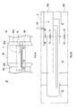
- FIG. 7A is a cross-sectional view taken along the line VIB-VIB in FIG. 6A and shows a state where no aperture is applied.
- FIG. 7B is a cross-sectional view taken along the line VIB-VIB in FIG. 6A and shows a state when a diaphragm is being applied.
- symbol of structures other than the tube cover 6 is used if necessary.
- “6” is used as a symbol indicating the tube cover, but this does not indicate the same configuration as the tube cover described in the background art. This is to clarify which part of the background art has caused the present invention by using a problem as a hint. However, this does not prevent the tube cover 6 of this embodiment from being used as a cover for other parts such as the tube cover 50 described in the background art.
- the tube cover 6 of the present embodiment includes a main body 60 that is formed in a cylindrical shape and has a split 6 a that is cracked along the axial direction. Also, the main body 60 is formed such that both end portions in the axial direction (portions having a predetermined width from both end portions in the axial direction of the main body 60) 60a and 60b are gradually reduced in diameter toward the respective end portions. Yes.
- both sides of the split 6a are brought together.
- this associated portion is referred to as a butt portion 61.
- the other end side ⁇ in the axial direction of the main body is attached to the pipe 9, one side of both sides of the split 6a is overlapped with the other side.
- the overlapped portion is referred to as a superposition portion 62.
- the main body 60 is formed in a shape in which the overlapping portion 62 is extended in the axial direction, and has a hole covering portion 63 that extends outward from the edge portion 60c on the other end side ⁇ of the main body 60. ing. Next, details such as the shapes of the abutting portion 61 and the overlapping portion 62 will be described.
- both side portions sandwiching the split 6a of the main body 60 are referred to as an upper portion 60t and a lower portion 60u.
- the shape of the portion corresponding to the abutment portion 61 in the upper portion 60t and the portion facing the lower portion 60u will be described with reference to FIG. 5A.
- the portion corresponding to the abutting portion 61 of the upper portion 60t has a portion 61a that swells for a while as it goes from the one end side ⁇ in the axial direction of the main body 60 to the other end ⁇ in the vicinity of the overlapping portion 62,
- the portion 61b closer to the overlapping portion 62 than the portion 61a that swells for a while is formed with a thickness that maintains the bulge.
- the other portion 61c of the abutting portion 61 is formed with a half thickness of the portion 61b that maintains the bulge.
- the portion corresponding to the abutting portion 61 in the upper side portion 60t is abutted with the portion corresponding to the abutting portion 61 in the lower side portion 60u, but the lower side portion 60u.
- the portion corresponding to the abutting portion 61 has the same thickness as the other portion 61c of the upper portion 60t throughout.
- the portions 61a and 61b other than the other portion 61c of the upper portion 60t are butted against the lower portion of the portions 61a and 61b, as indicated by hatching in FIG. 5A.
- the portion of the upper portion 60t corresponding to the overlapping portion 62 is formed with the same thickness as a whole when viewed in the direction of arrow E1 (see FIG. 4B) as shown in FIG. 5B.
- a stepped portion 62a is formed that rises upward for a while and rises one step with respect to the other portion 62c.
- the portion (step maintaining portion 62b) closer to the split 6a than the step portion 62a maintains a state where the step portion 62a is one step higher than the other portions.
- the portion corresponding to the abutting portion 61 in the upper portion 60t is in the vicinity of the split 6a and upward as it approaches the split 6a as shown in the direction of the arrow E2 (see FIG. 4B) as shown in FIG. 5C.
- the portion 61e closer to the split 6a than the portion 61d that swells for a while is formed with a thickness that maintains the bulge.
- the other portion 61f is formed with a half thickness of the portion 61e that maintains the bulge.
- the abutting portion 61 is abutted with the portions forming the thickness of the lower side portion 60 u and the upper side portion 60 t, but the overlapping portion 62 is a stepped portion.
- a moving space 8 is formed below the portion of the step maintaining portion 62b between the step portion 62a and the split 6a, and the tip of the step maintaining portion 62b is Overlaid on the side 60u.
- the moving space 8 is formed from a boundary portion between the abutting portion 61 and the overlapping portion 62 to an edge portion 60c on the other end side ⁇ of the main body 60.
- a hole 8 a is formed on the other end side ⁇ in the axial direction of the main body 60 by overlapping.
- the hole covering portion 63 covers and conceals the hole portion 8a from the outside. Further, since the tube cover 6 is formed with the moving space 8, when the main body 60 is squeezed in the circumferential direction, as shown in FIG. 7B, the lower side portion 60u can move in the moving space 8, Can be squeezed.
- the main body 60 of the tube cover 6 is formed of a hard material, the diameter can be reduced smoothly by forming the moving space 8.
- the hole cover 63 closes the hole 8a generated by forming the moving space 8. Therefore, it is possible to prevent heat from being radiated from the inside of the main body 60 through the hole 8a.
Abstract
This pipe cover has: a main body formed in a tubular shape and having a fissure split along the axial direction; an abutted section positioned at one end in the axial direction of the main body and at which both sides of the fissure of the main body are abutted during installation to piping; and an overlap section positioned at the other end in the axial direction of the main body and at which one of the two sides of the fissure of the main body overlaps the other side during installation to piping.
Description
本国際出願は、2014年3月31日に日本国特許庁に出願された日本国特許出願第2014-72442号に基づく優先権を主張するものであり、日本国特許出願第2014-72442号の全内容を参照により本国際出願に援用する。
This international application claims priority based on Japanese Patent Application No. 2014-72442 filed with the Japan Patent Office on March 31, 2014. The entire contents are incorporated herein by reference.
本発明は、排気管及びその他の管の管カバーに関する。
The present invention relates to an exhaust pipe and a pipe cover for other pipes.
車両の内燃機関としては、V型エンジンを始めとする高性能な内燃機関が用いられる場合がある。
高性能な内燃機関は、クランクシャフト軸が車両の進行方向に対して横方向(いわゆる横置き)となるように車両に搭載される場合が多く、この場合、ピストンがクランクシャフト軸の前後に並べられる。 As a vehicle internal combustion engine, a high-performance internal combustion engine such as a V-type engine may be used.
A high-performance internal combustion engine is often mounted on a vehicle such that the crankshaft shaft is transverse to the traveling direction of the vehicle (so-called horizontal placement). In this case, the pistons are arranged before and after the crankshaft shaft. It is done.
そのため、排気装置1は、図1に示すように、内燃機関の前後から排気ガスを取り込む形状に形成される。この排気装置1では、第一触媒10,11を備えるエキゾーストマニホールドが内燃機関の前後に取り付けられる。
Therefore, as shown in FIG. 1, the exhaust device 1 is formed in a shape that takes in exhaust gas from before and after the internal combustion engine. In the exhaust device 1, exhaust manifolds having first catalysts 10 and 11 are attached to the front and rear of the internal combustion engine.
また、後方の第一触媒11の後方には、各第一触媒10,11から送られてきた排気ガスを合流させるY字形状の排気合流管3が取り付けられ、排気合流管3のさらに後方には、第二触媒13が設置される。
Further, a Y-shaped exhaust merging pipe 3 for merging the exhaust gases sent from the first catalysts 10 and 11 is attached to the rear of the rear first catalyst 11, and further to the rear of the exhaust merging pipe 3. The second catalyst 13 is installed.
この排気合流管3は、後方側の第一触媒11の後方に取り付けられるが、前方側の第一触媒10とは離れているので、排気合流管3と第一触媒11とは、排気合流管3から延設された長尺な排気管12を介して接続される。
The exhaust merging pipe 3 is attached to the rear side of the first catalyst 11 on the rear side, but is separated from the first catalyst 10 on the front side. Therefore, the exhaust merging pipe 3 and the first catalyst 11 are connected to the exhaust merging pipe. 3 is connected through a long exhaust pipe 12 extending from 3.
このように、横置きした内燃機関に連結される排気装置1では、各第一触媒10,11から第二触媒13までの排気経路の長さが異なる。このような長さの異なる排気経路を有する排気管3,12を不等長の排気管と呼ぶ。
Thus, in the exhaust device 1 connected to the horizontally placed internal combustion engine, the lengths of the exhaust paths from the first catalysts 10 and 11 to the second catalyst 13 are different. The exhaust pipes 3 and 12 having the exhaust paths having different lengths are called unequal length exhaust pipes.
排気合流管3は、上流側の二股に分岐した部分と、下流側の部分とが、それぞれ枝部と呼ばれる。上流側の枝部のうち、第一触媒11に接続される枝部を第1枝部31、排気管12に接続される枝部を第2枝部32、下流側の枝部を第3枝部33とよぶ。
In the exhaust merging pipe 3, the upstream bifurcated part and the downstream part are called branches. Among the upstream branches, the branch connected to the first catalyst 11 is the first branch 31, the branch connected to the exhaust pipe 12 is the second branch 32, and the downstream branch is the third branch. It is called part 33.
次に、第1枝部31及び第3枝部33に取り付けられる第1保温具4、第2保温具5について、図2を用いて説明する。
第1保温具4は、排気合流管3を構成する第1枝部31、第2枝部32及び第3枝部33のうち、第一触媒11に接続される第1枝部31に取り付けられ、第2保温具5は、第二触媒13に接続される第3枝部33に取り付けられている。 Next, the 1stheat retention tool 4 and the 2nd heat insulation 5 attached to the 1st branch part 31 and the 3rd branch part 33 are demonstrated using FIG.
Thefirst heat insulator 4 is attached to the first branch portion 31 connected to the first catalyst 11 among the first branch portion 31, the second branch portion 32, and the third branch portion 33 constituting the exhaust gas merging pipe 3. The second heat retaining device 5 is attached to the third branch portion 33 connected to the second catalyst 13.
第1保温具4は、排気合流管3を構成する第1枝部31、第2枝部32及び第3枝部33のうち、第一触媒11に接続される第1枝部31に取り付けられ、第2保温具5は、第二触媒13に接続される第3枝部33に取り付けられている。 Next, the 1st
The
第1保温具4は、略円筒形状に形成された管カバー6と、管カバー6の内壁面と第1枝部31の外壁面との間に詰められた断熱材41とを備えている。
第2保温具5は、略円筒形状に形成された管カバー50と、管カバー50の内壁面と第3枝部33の外壁面との間に詰められた断熱材51とを備えている。 Thefirst heat insulator 4 includes a tube cover 6 formed in a substantially cylindrical shape, and a heat insulating material 41 packed between the inner wall surface of the tube cover 6 and the outer wall surface of the first branch portion 31.
The secondheat retaining device 5 includes a tube cover 50 formed in a substantially cylindrical shape, and a heat insulating material 51 packed between the inner wall surface of the tube cover 50 and the outer wall surface of the third branch portion 33.
第2保温具5は、略円筒形状に形成された管カバー50と、管カバー50の内壁面と第3枝部33の外壁面との間に詰められた断熱材51とを備えている。 The
The second
この管カバー6,50は、ステンレス製の遮熱板で構成されており、断熱材41,51は、グラスウールで構成されている。(特許文献1)
The tube covers 6 and 50 are made of a stainless steel heat shield, and the heat insulating materials 41 and 51 are made of glass wool. (Patent Document 1)
上述した排気合流管3のうち、第1枝部31は、直線状の管を鈍角状に折ったような形状に形成されている。
そして、この第1枝部31は、屈曲点31cから第2枝部32及び第3枝部33との合流点までの部分が(以下、第1部分31aと呼ぶ)、合流点から前方側に向かって直線状に延び、屈曲点31cよりも前方側の部分(以下、第2部分31bと呼ぶ)が、屈曲点31cから前方斜め上方に向かって傾斜して延びるように配置される。 In theexhaust merging pipe 3 described above, the first branch portion 31 is formed in a shape that is obtained by bending a straight pipe into an obtuse angle.
Thefirst branch portion 31 has a portion from the bending point 31c to the junction point of the second branch portion 32 and the third branch portion 33 (hereinafter referred to as the first portion 31a), and forward from the junction point. A portion extending in a straight line toward the front side of the bending point 31c (hereinafter referred to as a second portion 31b) is disposed so as to extend obliquely forward and upward from the bending point 31c.
そして、この第1枝部31は、屈曲点31cから第2枝部32及び第3枝部33との合流点までの部分が(以下、第1部分31aと呼ぶ)、合流点から前方側に向かって直線状に延び、屈曲点31cよりも前方側の部分(以下、第2部分31bと呼ぶ)が、屈曲点31cから前方斜め上方に向かって傾斜して延びるように配置される。 In the
The
しかし、第1枝部31は、鈍角状に曲がられているため、第1保温具4を構成する管カバー6が取り付けられる部分のうち、下流側(第2枝部32との合流側)は、その断面形状が、パイプ曲げ加工を行う際、材料のロット違いで曲げ部付近の形状がばらつく(例えば、楕円形状となる)ことがある。
However, since the first branch portion 31 is bent at an obtuse angle, the downstream side (the merging side with the second branch portion 32) of the portion to which the tube cover 6 constituting the first heat insulator 4 is attached. When the pipe is bent, the cross-sectional shape may vary in the vicinity of the bent portion due to the difference in material lot (for example, an elliptical shape).
そのため、管カバー6を略円筒形状に形成しても、管カバー6の下流側に位置する筒口の縁部と、第1枝部31の外周面との間に隙間が出来てしまい、その隙間の部分が溶接時に未溶接となってしまって、管カバー6が第1枝部31からの放熱を十分に抑制できなくなる可能性があった。
Therefore, even if the tube cover 6 is formed in a substantially cylindrical shape, a gap is formed between the edge of the tube port located on the downstream side of the tube cover 6 and the outer peripheral surface of the first branch portion 31, and the gap This part may become unwelded during welding, and the tube cover 6 may not be able to sufficiently suppress the heat radiation from the first branch portion 31.
また、管カバー6の筒口と第1枝部31の外周面との間に隙間ができてしまうと、管カバー6を第1枝部31に溶接によって固定することが困難になる可能性があった。
本発明の1局面では、配管の形状がばらついても、管カバーを配管に取り付けたとき、管カバーの筒口の縁部と配管との間に隙間が生じにくい管カバーを提供することが望ましい。 In addition, if there is a gap between the tube port of thetube cover 6 and the outer peripheral surface of the first branch portion 31, it may be difficult to fix the tube cover 6 to the first branch portion 31 by welding. It was.
In one aspect of the present invention, it is desirable to provide a tube cover that is less likely to cause a gap between the edge of the tube port of the tube cover and the piping when the tube cover is attached to the piping even if the shape of the piping varies.
本発明の1局面では、配管の形状がばらついても、管カバーを配管に取り付けたとき、管カバーの筒口の縁部と配管との間に隙間が生じにくい管カバーを提供することが望ましい。 In addition, if there is a gap between the tube port of the
In one aspect of the present invention, it is desirable to provide a tube cover that is less likely to cause a gap between the edge of the tube port of the tube cover and the piping when the tube cover is attached to the piping even if the shape of the piping varies.
本発明の1局面の管カバーは、
筒状に形成され、軸方向に沿って割れた割目を有する本体と、
前記軸方向の一端側に位置し、配管に取り付けられるとき、前記割目の両側が付き合わされる突合部と、
前記軸方向の他端側に位置し、配管に取り付けられるとき、前記割目の両側のうち一方の側が他方の側に重ね合わされる重合部と
を有する。 The tube cover of one aspect of the present invention is
A main body that is formed in a cylindrical shape and has a split that is split along the axial direction;
Abutting portions that are located on one end side in the axial direction and are attached to the pipe, and on both sides of the split,
It is located on the other end side in the axial direction, and when attached to the pipe, one side of the both sides of the split is superposed on the other side.
この管カバーは、軸方向の他端側に位置する筒口が、配管が曲がっている側に向けて取り付けられる。すると、曲げにより配管の断面形状がばらついても、この管カバーは、軸方向の他端側が重合部によって絞ることができるので、軸方向の他端側に位置する筒口の縁部と配管の外周面との間に隙間を生じさせることなく、配管に取り付けることができる。したがって、この管カバーを用いると、溶接によって管カバーを配管にしっかり固定することができる。
This tube cover is attached so that the tube port located on the other end side in the axial direction faces the side where the pipe is bent. Then, even if the cross-sectional shape of the pipe varies due to bending, this pipe cover can be squeezed on the other end side in the axial direction by the overlapping portion, so the edge of the tube port located on the other end side in the axial direction and the outer periphery of the pipe It can be attached to the piping without causing a gap between the surface. Therefore, when this pipe cover is used, the pipe cover can be firmly fixed to the pipe by welding.
上記において、重合部は、割目の両側のうち一方の側を他方の側に重ね合わせたとき、割目の両側のうち一方の側の下に、本体を縮径する方向に他方の側が移動させる移動空間が形成される形状に形成してもよい。
In the above, when one side of both sides of the split is overlapped with the other side, the other side moves in the direction of reducing the diameter of the main body under one side of both sides of the split You may form in the shape in which the movement space to be formed is formed.
管カバーの本体は、硬質な材料で形成されるため、このような移動空間を形成しておけば、スムーズに縮径することができる。
尚、移動空間は、その大きさが大きすぎると溶接欠陥が発生しやすくなるため、適切な空間がよい。 Since the main body of the tube cover is formed of a hard material, if such a movement space is formed, the diameter can be smoothly reduced.
In addition, since the movement space will become easy to generate | occur | produce a welding defect if the magnitude | size is too large, suitable space is good.
上記において、軸方向の他端から延設された孔覆部であって、重ねあわせによって軸方向の他端側に形成される孔部を覆う孔覆部を有してもよい。
このようにすると、孔覆部が、重ねあわせによって軸方向の他端側に形成される孔部を閉じるので、本体内から孔部を解して熱が放熱されることを抑制できる。 In the above, a hole covering portion that extends from the other end in the axial direction, and covers a hole formed on the other end side in the axial direction by overlapping may be provided.
If it does in this way, since a hole covering part closes the hole formed in the other end side of an axial direction by superposition, it can control that a hole is opened from the inside of a main part and heat is radiated.
尚、重合部が、割目の両側のうち一方の側を他方の側に重ね合わせたとき、割目の両側のうち一方の側の下に、本体を縮径する方向に他方の側が移動させる移動空間が形成される形状に形成されている場合、この孔部は、移動空間によって形成される。
In addition, when the overlapping portion overlaps one side of both sides of the split with the other side, the other side moves below the one side of both sides of the split in the direction of reducing the diameter of the main body. In the case where the moving space is formed in a shape, the hole is formed by the moving space.
1… 排気装置 3… 排気合流管 6… 管カバー 6a… 割目 8… 移動空間
8a… 孔部 9… 配管 50… 管カバー 60… 本体 60c… 縁部
60u… 下側部 60t… 上側部 61… 突合部 62… 重合部
62a… 段差部 62b… 段差維持部 63… 孔覆部 DESCRIPTION OF SYMBOLS 1 ...Exhaust device 3 ... Exhaust merge pipe 6 ... Pipe cover 6a ... Split 8 ... Movement space 8a ... Hole 9 ... Pipe 50 ... Pipe cover 60 ... Main body 60c ... Edge 60u ... Lower part 60t ... Upper part 61 ... Abutting part 62 ... Overlapping part 62a ... Step part 62b ... Step maintaining part 63 ... Hole covering part
8a… 孔部 9… 配管 50… 管カバー 60… 本体 60c… 縁部
60u… 下側部 60t… 上側部 61… 突合部 62… 重合部
62a… 段差部 62b… 段差維持部 63… 孔覆部 DESCRIPTION OF SYMBOLS 1 ...
以下に本発明の実施形態を図面と共に説明する。
本実施形態の管カバー6について説明する。
尚、この管カバー6が取り付けられる排気合流管3、及び、この排気合流管3が取り付けられる排気装置1については、背景技術の欄ですでに説明したので、以下では、その説明は省略する。 Embodiments of the present invention will be described below with reference to the drawings.
Thetube cover 6 of this embodiment will be described.
Since theexhaust merging pipe 3 to which the pipe cover 6 is attached and the exhaust device 1 to which the exhaust merging pipe 3 is attached have already been described in the background art section, description thereof will be omitted below.
本実施形態の管カバー6について説明する。
尚、この管カバー6が取り付けられる排気合流管3、及び、この排気合流管3が取り付けられる排気装置1については、背景技術の欄ですでに説明したので、以下では、その説明は省略する。 Embodiments of the present invention will be described below with reference to the drawings.
The
Since the
また、管カバー6以外の構成の符号については、必要な場合、背景技術の欄で説明した符号を用いる。
また、本実施形態では、管カバーを示す符号として「6」を用いているが、背景技術で記載した管カバーと同じ構成であることを示すものではない。背景技術のどの部分に生じた問題をヒントとして、本発明がなされたのか明確にするためである。しかしこれは、本実施形態の管カバー6を、背景技術に記載した管カバー50など、他の部分のカバーとして用いることを妨げるものではない。 Moreover, about the code | symbol of structures other than thetube cover 6, the code | symbol demonstrated in the column of background art is used if necessary.
Further, in the present embodiment, “6” is used as a symbol indicating the tube cover, but this does not indicate the same configuration as the tube cover described in the background art. This is to clarify which part of the background art has caused the present invention by using a problem as a hint. However, this does not prevent thetube cover 6 of this embodiment from being used as a cover for other parts such as the tube cover 50 described in the background art.
また、本実施形態では、管カバーを示す符号として「6」を用いているが、背景技術で記載した管カバーと同じ構成であることを示すものではない。背景技術のどの部分に生じた問題をヒントとして、本発明がなされたのか明確にするためである。しかしこれは、本実施形態の管カバー6を、背景技術に記載した管カバー50など、他の部分のカバーとして用いることを妨げるものではない。 Moreover, about the code | symbol of structures other than the
Further, in the present embodiment, “6” is used as a symbol indicating the tube cover, but this does not indicate the same configuration as the tube cover described in the background art. This is to clarify which part of the background art has caused the present invention by using a problem as a hint. However, this does not prevent the
本実施形態の管カバー6は、図3に示すように、筒状に形成され、軸方向に沿って割れた割目6aを有する本体60を備えている。
また、この本体60は、その軸方向の両端部分(本体60の軸方向の両端部から所定の幅を有する部分)60a,60bが、各端部に向かって暫時縮径する形状に形成されている。 As shown in FIG. 3, thetube cover 6 of the present embodiment includes a main body 60 that is formed in a cylindrical shape and has a split 6 a that is cracked along the axial direction.
Also, themain body 60 is formed such that both end portions in the axial direction (portions having a predetermined width from both end portions in the axial direction of the main body 60) 60a and 60b are gradually reduced in diameter toward the respective end portions. Yes.
また、この本体60は、その軸方向の両端部分(本体60の軸方向の両端部から所定の幅を有する部分)60a,60bが、各端部に向かって暫時縮径する形状に形成されている。 As shown in FIG. 3, the
Also, the
この本体60の軸方向の一端側αは、配管9に取り付けられるとき、割目6aの両側が付き合わされる。この付きあわされる部分を、以下、突合部61と呼ぶ。
一方、この本体の軸方向の他端側βは、配管9に取り付けられるとき、割目6aの両側のうち一方の側が他方の側に重ね合わされる。この重ね合わされる部分を、以下、重合部62と呼ぶ。 When one end side α in the axial direction of themain body 60 is attached to the pipe 9, both sides of the split 6a are brought together. Hereinafter, this associated portion is referred to as a butt portion 61.
On the other hand, when the other end side β in the axial direction of the main body is attached to thepipe 9, one side of both sides of the split 6a is overlapped with the other side. Hereinafter, the overlapped portion is referred to as a superposition portion 62.
一方、この本体の軸方向の他端側βは、配管9に取り付けられるとき、割目6aの両側のうち一方の側が他方の側に重ね合わされる。この重ね合わされる部分を、以下、重合部62と呼ぶ。 When one end side α in the axial direction of the
On the other hand, when the other end side β in the axial direction of the main body is attached to the
また、この本体60は、重合部62を軸方向に延設した形状に形成され、本体60の他端側βの縁部60cよりも外側に向かって延設された孔覆部63を有している。
次に、突合部61及び重合部62の形状等の詳細について説明する。 Further, themain body 60 is formed in a shape in which the overlapping portion 62 is extended in the axial direction, and has a hole covering portion 63 that extends outward from the edge portion 60c on the other end side β of the main body 60. ing.
Next, details such as the shapes of the abuttingportion 61 and the overlapping portion 62 will be described.
次に、突合部61及び重合部62の形状等の詳細について説明する。 Further, the
Next, details such as the shapes of the abutting
ここで、これら突合部61及び重合部62を説明するにあたり、図4Aに示すように、本体60の割目6aを挟んだ両側部を、上側部60t及び下側部60uと呼ぶ。
上側部60tのうち突合部61に対応する部分の形状であって、下側部60uに対向する部分の形状について、図5Aを用いて説明する。 Here, in describing the abuttingportion 61 and the overlapping portion 62, as shown in FIG. 4A, both side portions sandwiching the split 6a of the main body 60 are referred to as an upper portion 60t and a lower portion 60u.
The shape of the portion corresponding to theabutment portion 61 in the upper portion 60t and the portion facing the lower portion 60u will be described with reference to FIG. 5A.
上側部60tのうち突合部61に対応する部分の形状であって、下側部60uに対向する部分の形状について、図5Aを用いて説明する。 Here, in describing the abutting
The shape of the portion corresponding to the
上側部60tのうち突合部61に対応する部分には、重合部62の近傍で、本体60の軸方向の一端側αから他端側βに向かうにつれて上方に向かって暫時膨らむ部分61aがあり、この暫時膨らむ部分61aよりも重合部62側の部分61bは、その膨らみを維持した厚みで形成されている。この突合部61のその他の部分61cは、膨らみを維持した部分61bの半分の厚みで形成されている。
The portion corresponding to the abutting portion 61 of the upper portion 60t has a portion 61a that swells for a while as it goes from the one end side α in the axial direction of the main body 60 to the other end β in the vicinity of the overlapping portion 62, The portion 61b closer to the overlapping portion 62 than the portion 61a that swells for a while is formed with a thickness that maintains the bulge. The other portion 61c of the abutting portion 61 is formed with a half thickness of the portion 61b that maintains the bulge.
そして、この本体60が配管9に取り付けられるとき、上側部60tのうち突合部61に対応する部分は、下側部60uのうち突合部61に対応する部分と突き合わされるが、下側部60uのうち突合部61に対応する部分は、全体に渡り、上側部60tのその他の部分61cと同じ厚みを形成している。
When the main body 60 is attached to the pipe 9, the portion corresponding to the abutting portion 61 in the upper side portion 60t is abutted with the portion corresponding to the abutting portion 61 in the lower side portion 60u, but the lower side portion 60u. Of these, the portion corresponding to the abutting portion 61 has the same thickness as the other portion 61c of the upper portion 60t throughout.
そのため、上側部60tのその他の部分61c以外の部分61a、61bでは、図5A中に斜線で示したように、それらの部分61a、61bのうち下方部分に突き合わされる。
Therefore, the portions 61a and 61b other than the other portion 61c of the upper portion 60t are butted against the lower portion of the portions 61a and 61b, as indicated by hatching in FIG. 5A.
次に、上側部60tのうち突合部61と重合部62とに対応する部分であって、突合部61と重合部62との境界部分を切断した、それぞれの厚みを形成する部分の形状について、図5B及び図5Cを用いて説明する。
Next, in the upper part 60t, the part corresponding to the abutting part 61 and the overlapping part 62, and cutting the boundary part between the abutting part 61 and the overlapping part 62, the shape of the part forming each thickness, This will be described with reference to FIGS. 5B and 5C.
上側部60tのうち重合部62に対応する部分は、図5Bに示すように矢印E1(図4B参照)の方向でみると、全体に同じ厚みで形成されている。重合部62に対応する部分のうち割目6aの近傍には、上方に向かって暫時盛り上がり、その他の部分62cに対し一段上がる段差部62aが形成されている。重合部62に対応する部分のうち、段差部62aよりも割目6a側の部分(段差維持部62b)は、段差部62aにおいて他の部分に対し一段上がった状態を維持している。
The portion of the upper portion 60t corresponding to the overlapping portion 62 is formed with the same thickness as a whole when viewed in the direction of arrow E1 (see FIG. 4B) as shown in FIG. 5B. In the vicinity of the split 6a in the portion corresponding to the overlapping portion 62, a stepped portion 62a is formed that rises upward for a while and rises one step with respect to the other portion 62c. Of the portion corresponding to the overlapping portion 62, the portion (step maintaining portion 62b) closer to the split 6a than the step portion 62a maintains a state where the step portion 62a is one step higher than the other portions.
一方、上側部60tのうち突合部61に対応する部分は、図5Cに示すように矢印E2(図4B参照)の方向でみると、割目6aの近傍で、割目6aに近づくにつれて上方に向かって暫時膨らむ部分61dがある。この暫時膨らむ部分61dよりも割目6a側の部分61eは、その膨らみを維持した厚みで形成されている。その他の部分61fは、膨らみを維持した部分61eの半分の厚みで形成されている。
On the other hand, the portion corresponding to the abutting portion 61 in the upper portion 60t is in the vicinity of the split 6a and upward as it approaches the split 6a as shown in the direction of the arrow E2 (see FIG. 4B) as shown in FIG. 5C. There is a portion 61d that swells for a while. The portion 61e closer to the split 6a than the portion 61d that swells for a while is formed with a thickness that maintains the bulge. The other portion 61f is formed with a half thickness of the portion 61e that maintains the bulge.
この管カバー6は、本体60が配管9に取り付けられると、突合部61については、下側部60uと上側部60tの厚みを形成する部分が突き合わされるが、重合部62については、段差部62aを設けることによって、段差維持部62bのうち、段差部62aから割目6aまでの間の部分の下方には、移動空間8が形成される、また、段差維持部62bの先端部分は、下側部60u上に重ねられる。
In the tube cover 6, when the main body 60 is attached to the pipe 9, the abutting portion 61 is abutted with the portions forming the thickness of the lower side portion 60 u and the upper side portion 60 t, but the overlapping portion 62 is a stepped portion. By providing 62a, a moving space 8 is formed below the portion of the step maintaining portion 62b between the step portion 62a and the split 6a, and the tip of the step maintaining portion 62b is Overlaid on the side 60u.
この移動空間8は、図6A、図6B及び図6Cに示すように、突合部61と重合部62との境界部分から本体60の他端側βの縁部60cまで形成される。
このように、移動空間8が形成されると、図7Aに示すように、本体60の軸方向の他端側βには、重ねあわせによって孔部8aが形成される。 As shown in FIGS. 6A, 6B, and 6C, the movingspace 8 is formed from a boundary portion between the abutting portion 61 and the overlapping portion 62 to an edge portion 60c on the other end side β of the main body 60.
Thus, when the movingspace 8 is formed, as shown in FIG. 7A, a hole 8 a is formed on the other end side β in the axial direction of the main body 60 by overlapping.
このように、移動空間8が形成されると、図7Aに示すように、本体60の軸方向の他端側βには、重ねあわせによって孔部8aが形成される。 As shown in FIGS. 6A, 6B, and 6C, the moving
Thus, when the moving
そのため、前述した孔覆部63(図1参照)は、この孔部8aを外側から覆って隠している。
また、この管カバー6は、この移動空間8が形成されるため、本体60を円周方向に絞ると、図7Bに示すように、下側部60uが移動空間8を移動可能な分だけ、絞ることができる。 Therefore, the hole covering portion 63 (see FIG. 1) described above covers and conceals the hole portion 8a from the outside.
Further, since thetube cover 6 is formed with the moving space 8, when the main body 60 is squeezed in the circumferential direction, as shown in FIG. 7B, the lower side portion 60u can move in the moving space 8, Can be squeezed.
また、この管カバー6は、この移動空間8が形成されるため、本体60を円周方向に絞ると、図7Bに示すように、下側部60uが移動空間8を移動可能な分だけ、絞ることができる。 Therefore, the hole covering portion 63 (see FIG. 1) described above covers and conceals the hole portion 8a from the outside.
Further, since the
以上説明した管カバーは次のような特徴的な作用効果を有する。
この管カバー6は、軸方向の他端側βが重合部62によって絞ることができるので、配管9に対し管カバー6が取り付けられる部分のうち、配管9のいずれかの端部側の断面形状がばらついても、その端部側の本体60の縁部60cと管9との間に隙間ができないように取り付けることができる。また、このとき、ばらつきの度合い(非円形の度合い、扁平の度合いなど)によって移動空間8も閉じられる。 The tube cover described above has the following characteristic operational effects.
Since thistube cover 6 can be narrowed at the other end side β in the axial direction by the overlapping portion 62, the cross-sectional shape of one end side of the pipe 9 in the portion where the pipe cover 6 is attached to the pipe 9. Even if it varies, it can be attached so that there is no gap between the edge 60c of the main body 60 on the end side and the tube 9. At this time, the moving space 8 is also closed depending on the degree of variation (degree of non-circularity, degree of flatness, etc.).
この管カバー6は、軸方向の他端側βが重合部62によって絞ることができるので、配管9に対し管カバー6が取り付けられる部分のうち、配管9のいずれかの端部側の断面形状がばらついても、その端部側の本体60の縁部60cと管9との間に隙間ができないように取り付けることができる。また、このとき、ばらつきの度合い(非円形の度合い、扁平の度合いなど)によって移動空間8も閉じられる。 The tube cover described above has the following characteristic operational effects.
Since this
また、管カバー6の本体60は、硬質な材料で形成されるため、移動空間8を形成することによってスムーズに縮径することができる。
また、管カバー6は、管カバー6を絞っても孔部8aが塞がらず孔部8aが残ってしまっても、孔覆部63が、移動空間8を形成することによって生ずる孔部8aを閉じるので、本体60内から孔部8aを解して熱が放熱されることを抑止することができる。
[他の実施形態]
上記実施形態で説明した管カバー6はあくまでも一例であり、これに限定されるものではない。 Moreover, since themain body 60 of the tube cover 6 is formed of a hard material, the diameter can be reduced smoothly by forming the moving space 8.
In addition, even if thetube cover 6 is squeezed and the hole 8a is not blocked and the hole 8a remains, the hole cover 63 closes the hole 8a generated by forming the moving space 8. Therefore, it is possible to prevent heat from being radiated from the inside of the main body 60 through the hole 8a.
[Other Embodiments]
Thetube cover 6 described in the above embodiment is merely an example, and the present invention is not limited to this.
また、管カバー6は、管カバー6を絞っても孔部8aが塞がらず孔部8aが残ってしまっても、孔覆部63が、移動空間8を形成することによって生ずる孔部8aを閉じるので、本体60内から孔部8aを解して熱が放熱されることを抑止することができる。
[他の実施形態]
上記実施形態で説明した管カバー6はあくまでも一例であり、これに限定されるものではない。 Moreover, since the
In addition, even if the
[Other Embodiments]
The
Claims (3)
- 筒状に形成され、軸方向に沿って割れた割目を有する本体と、
前記軸方向の一端側に位置し、配管に取り付けられるとき、前記割目の両側が付き合わされる突合部と、
前記軸方向の他端側に位置し、配管に取り付けられるとき、前記割目の両側のうち一方の側が他方の側に重ね合わされる重合部と
を有する管カバー。 A main body that is formed in a cylindrical shape and has a split that is split along the axial direction;
Abutting portions that are located on one end side in the axial direction and are attached to the pipe, and on both sides of the split,
A pipe cover having an overlapping portion that is positioned on the other end side in the axial direction and overlapped with one side of the both sides of the split when the pipe is attached to the pipe. - 請求項1に記載の管カバーにおいて、
前記重合部は、前記割目の両側のうち一方の側を他方の側に重ね合わせたとき、前記割目の両側のうち一方の側の下に、前記本体を縮径する方向に前記他方の側が移動させる移動空間を形成する形状に形成されている管カバー。 The tube cover according to claim 1,
The overlapping portion is configured such that when one side of both sides of the split is overlapped with the other side, the other side of the other side in the direction of reducing the diameter of the main body is below one side of the both sides of the split. A tube cover formed in a shape that forms a moving space to be moved by the side. - 請求項1,2いずれか1項に記載の管カバーにおいて、
前記軸方向の他端から延設された孔覆部であって、前記重ねあわせによって前記軸方向の他端側に形成される孔部を覆う孔覆部を有する管カバー。 The tube cover according to any one of claims 1 and 2,
A tube cover having a hole covering portion extending from the other end in the axial direction and covering a hole formed on the other end side in the axial direction by the overlapping.
Priority Applications (1)
| Application Number | Priority Date | Filing Date | Title |
|---|---|---|---|
| JP2016511967A JPWO2015152303A1 (en) | 2014-03-31 | 2015-03-31 | Tube cover |
Applications Claiming Priority (2)
| Application Number | Priority Date | Filing Date | Title |
|---|---|---|---|
| JP2014072442 | 2014-03-31 | ||
| JP2014-072442 | 2014-03-31 |
Publications (1)
| Publication Number | Publication Date |
|---|---|
| WO2015152303A1 true WO2015152303A1 (en) | 2015-10-08 |
Family
ID=54240621
Family Applications (1)
| Application Number | Title | Priority Date | Filing Date |
|---|---|---|---|
| PCT/JP2015/060271 WO2015152303A1 (en) | 2014-03-31 | 2015-03-31 | Pipe cover |
Country Status (2)
| Country | Link |
|---|---|
| JP (1) | JPWO2015152303A1 (en) |
| WO (1) | WO2015152303A1 (en) |
Citations (4)
| Publication number | Priority date | Publication date | Assignee | Title |
|---|---|---|---|---|
| US3588965A (en) * | 1966-04-06 | 1971-06-29 | Ultronix Inc | Insulated pipeline jacketing systems |
| DE2928165A1 (en) * | 1979-07-12 | 1981-01-29 | Steffens & Co | Axially slotted galvanised steel tube - is used as support for lagging and has oblong rivet location holes |
| JPH0477094U (en) * | 1990-11-19 | 1992-07-06 | ||
| JPH10508938A (en) * | 1995-05-19 | 1998-09-02 | サン−ゴバン インダストリアル セラミックス,インコーポレイティド | Novel heat-resistant shield structure of superheater |
Family Cites Families (1)
| Publication number | Priority date | Publication date | Assignee | Title |
|---|---|---|---|---|
| CN104584709B (en) * | 2012-08-27 | 2018-04-06 | 古河As株式会社 | Electromagnetic shield pipe |
-
2015
- 2015-03-31 WO PCT/JP2015/060271 patent/WO2015152303A1/en active Application Filing
- 2015-03-31 JP JP2016511967A patent/JPWO2015152303A1/en active Pending
Patent Citations (4)
| Publication number | Priority date | Publication date | Assignee | Title |
|---|---|---|---|---|
| US3588965A (en) * | 1966-04-06 | 1971-06-29 | Ultronix Inc | Insulated pipeline jacketing systems |
| DE2928165A1 (en) * | 1979-07-12 | 1981-01-29 | Steffens & Co | Axially slotted galvanised steel tube - is used as support for lagging and has oblong rivet location holes |
| JPH0477094U (en) * | 1990-11-19 | 1992-07-06 | ||
| JPH10508938A (en) * | 1995-05-19 | 1998-09-02 | サン−ゴバン インダストリアル セラミックス,インコーポレイティド | Novel heat-resistant shield structure of superheater |
Also Published As
| Publication number | Publication date |
|---|---|
| JPWO2015152303A1 (en) | 2017-04-13 |
Similar Documents
| Publication | Publication Date | Title |
|---|---|---|
| US10570779B2 (en) | Turbine housing | |
| JP4624459B2 (en) | Exhaust manifold | |
| JP6114244B2 (en) | Vehicle exhaust system | |
| WO2015152303A1 (en) | Pipe cover | |
| JP2010127097A (en) | Exhaust manifold | |
| JP5829995B2 (en) | Exhaust system members | |
| US8950178B2 (en) | Exhaust device of multi-cylinder engine | |
| JP2007321569A (en) | Muffler structure | |
| JP6185501B2 (en) | Heat insulator | |
| JP5675327B2 (en) | Protective tube fixing structure | |
| JP2020084776A (en) | Exhaust structure | |
| JP2016056788A (en) | Exhaust pipe with catalyst mounted on vehicle | |
| US20180347440A1 (en) | Exhaust system support structure | |
| JP2013024201A (en) | Exhaust apparatus for internal combustion engine | |
| KR101619627B1 (en) | Welding structure of inlet portion in engine | |
| JP6280209B2 (en) | Heat insulation structure of exhaust confluence pipe | |
| JP2016153607A (en) | Turbine housing | |
| CN105156194A (en) | Decorative tail pipe for automobile exhaust pipe | |
| US20200217237A1 (en) | Heat shield having a sealing element | |
| JP2015045313A (en) | Muffler for vehicle | |
| JP7364549B2 (en) | Exhaust pipe | |
| JP2010138835A (en) | Exhaust manifold structure for internal combustion engine | |
| JP7148560B2 (en) | Sensor boss and sensor boss mounting structure | |
| JP2022009107A5 (en) | ||
| JP2016176423A (en) | Heat insulator |
Legal Events
| Date | Code | Title | Description |
|---|---|---|---|
| 121 | Ep: the epo has been informed by wipo that ep was designated in this application |
Ref document number: 15773961 Country of ref document: EP Kind code of ref document: A1 |
|
| ENP | Entry into the national phase |
Ref document number: 2016511967 Country of ref document: JP Kind code of ref document: A |
|
| NENP | Non-entry into the national phase | ||
| 122 | Ep: pct application non-entry in european phase |
Ref document number: 15773961 Country of ref document: EP Kind code of ref document: A1 |