WO2015147149A1 - 自律走行作業車両 - Google Patents
自律走行作業車両 Download PDFInfo
- Publication number
- WO2015147149A1 WO2015147149A1 PCT/JP2015/059337 JP2015059337W WO2015147149A1 WO 2015147149 A1 WO2015147149 A1 WO 2015147149A1 JP 2015059337 W JP2015059337 W JP 2015059337W WO 2015147149 A1 WO2015147149 A1 WO 2015147149A1
- Authority
- WO
- WIPO (PCT)
- Prior art keywords
- work vehicle
- control device
- person
- autonomous traveling
- sensor
- Prior art date
- Legal status (The legal status is an assumption and is not a legal conclusion. Google has not performed a legal analysis and makes no representation as to the accuracy of the status listed.)
- Ceased
Links
Images



Classifications
-
- G—PHYSICS
- G05—CONTROLLING; REGULATING
- G05D—SYSTEMS FOR CONTROLLING OR REGULATING NON-ELECTRIC VARIABLES
- G05D1/00—Control of position, course, altitude or attitude of land, water, air or space vehicles, e.g. using automatic pilots
- G05D1/20—Control system inputs
- G05D1/24—Arrangements for determining position or orientation
- G05D1/247—Arrangements for determining position or orientation using signals provided by artificial sources external to the vehicle, e.g. navigation beacons
- G05D1/248—Arrangements for determining position or orientation using signals provided by artificial sources external to the vehicle, e.g. navigation beacons generated by satellites, e.g. GPS
-
- A—HUMAN NECESSITIES
- A01—AGRICULTURE; FORESTRY; ANIMAL HUSBANDRY; HUNTING; TRAPPING; FISHING
- A01B—SOIL WORKING IN AGRICULTURE OR FORESTRY; PARTS, DETAILS, OR ACCESSORIES OF AGRICULTURAL MACHINES OR IMPLEMENTS, IN GENERAL
- A01B69/00—Steering of agricultural machines or implements; Guiding agricultural machines or implements on a desired track
- A01B69/007—Steering or guiding of agricultural vehicles, e.g. steering of the tractor to keep the plough in the furrow
- A01B69/008—Steering or guiding of agricultural vehicles, e.g. steering of the tractor to keep the plough in the furrow automatic
-
- B—PERFORMING OPERATIONS; TRANSPORTING
- B60—VEHICLES IN GENERAL
- B60Q—ARRANGEMENT OF SIGNALLING OR LIGHTING DEVICES, THE MOUNTING OR SUPPORTING THEREOF OR CIRCUITS THEREFOR, FOR VEHICLES IN GENERAL
- B60Q1/00—Arrangement of optical signalling or lighting devices, the mounting or supporting thereof or circuits therefor
- B60Q1/26—Arrangement of optical signalling or lighting devices, the mounting or supporting thereof or circuits therefor the devices being primarily intended to indicate the vehicle, or parts thereof, or to give signals, to other traffic
-
- B—PERFORMING OPERATIONS; TRANSPORTING
- B60—VEHICLES IN GENERAL
- B60Q—ARRANGEMENT OF SIGNALLING OR LIGHTING DEVICES, THE MOUNTING OR SUPPORTING THEREOF OR CIRCUITS THEREFOR, FOR VEHICLES IN GENERAL
- B60Q5/00—Arrangement or adaptation of acoustic signal devices
- B60Q5/005—Arrangement or adaptation of acoustic signal devices automatically actuated
- B60Q5/006—Arrangement or adaptation of acoustic signal devices automatically actuated indicating risk of collision between vehicles or with pedestrians
-
- G—PHYSICS
- G05—CONTROLLING; REGULATING
- G05D—SYSTEMS FOR CONTROLLING OR REGULATING NON-ELECTRIC VARIABLES
- G05D1/00—Control of position, course, altitude or attitude of land, water, air or space vehicles, e.g. using automatic pilots
- G05D1/02—Control of position or course in two dimensions
- G05D1/021—Control of position or course in two dimensions specially adapted to land vehicles
- G05D1/0231—Control of position or course in two dimensions specially adapted to land vehicles using optical position detecting means
- G05D1/0242—Control of position or course in two dimensions specially adapted to land vehicles using optical position detecting means using non-visible light signals, e.g. IR or UV signals
-
- G—PHYSICS
- G05—CONTROLLING; REGULATING
- G05D—SYSTEMS FOR CONTROLLING OR REGULATING NON-ELECTRIC VARIABLES
- G05D1/00—Control of position, course, altitude or attitude of land, water, air or space vehicles, e.g. using automatic pilots
- G05D1/02—Control of position or course in two dimensions
- G05D1/021—Control of position or course in two dimensions specially adapted to land vehicles
- G05D1/0231—Control of position or course in two dimensions specially adapted to land vehicles using optical position detecting means
- G05D1/0246—Control of position or course in two dimensions specially adapted to land vehicles using optical position detecting means using a video camera in combination with image processing means
-
- G—PHYSICS
- G05—CONTROLLING; REGULATING
- G05D—SYSTEMS FOR CONTROLLING OR REGULATING NON-ELECTRIC VARIABLES
- G05D1/00—Control of position, course, altitude or attitude of land, water, air or space vehicles, e.g. using automatic pilots
- G05D1/02—Control of position or course in two dimensions
- G05D1/021—Control of position or course in two dimensions specially adapted to land vehicles
- G05D1/0255—Control of position or course in two dimensions specially adapted to land vehicles using acoustic signals, e.g. ultra-sonic singals
-
- G—PHYSICS
- G05—CONTROLLING; REGULATING
- G05D—SYSTEMS FOR CONTROLLING OR REGULATING NON-ELECTRIC VARIABLES
- G05D1/00—Control of position, course, altitude or attitude of land, water, air or space vehicles, e.g. using automatic pilots
- G05D1/02—Control of position or course in two dimensions
- G05D1/021—Control of position or course in two dimensions specially adapted to land vehicles
- G05D1/0276—Control of position or course in two dimensions specially adapted to land vehicles using signals provided by a source external to the vehicle
- G05D1/0278—Control of position or course in two dimensions specially adapted to land vehicles using signals provided by a source external to the vehicle using satellite positioning signals, e.g. GPS
-
- G—PHYSICS
- G05—CONTROLLING; REGULATING
- G05D—SYSTEMS FOR CONTROLLING OR REGULATING NON-ELECTRIC VARIABLES
- G05D1/00—Control of position, course, altitude or attitude of land, water, air or space vehicles, e.g. using automatic pilots
- G05D1/02—Control of position or course in two dimensions
- G05D1/021—Control of position or course in two dimensions specially adapted to land vehicles
- G05D1/0276—Control of position or course in two dimensions specially adapted to land vehicles using signals provided by a source external to the vehicle
- G05D1/028—Control of position or course in two dimensions specially adapted to land vehicles using signals provided by a source external to the vehicle using a RF signal
-
- G—PHYSICS
- G05—CONTROLLING; REGULATING
- G05D—SYSTEMS FOR CONTROLLING OR REGULATING NON-ELECTRIC VARIABLES
- G05D1/00—Control of position, course, altitude or attitude of land, water, air or space vehicles, e.g. using automatic pilots
- G05D1/20—Control system inputs
- G05D1/24—Arrangements for determining position or orientation
- G05D1/243—Means capturing signals occurring naturally from the environment, e.g. ambient optical, acoustic, gravitational or magnetic signals
-
- G—PHYSICS
- G05—CONTROLLING; REGULATING
- G05D—SYSTEMS FOR CONTROLLING OR REGULATING NON-ELECTRIC VARIABLES
- G05D1/00—Control of position, course, altitude or attitude of land, water, air or space vehicles, e.g. using automatic pilots
- G05D1/60—Intended control result
- G05D1/617—Safety or protection, e.g. defining protection zones around obstacles or avoiding hazards
-
- G—PHYSICS
- G05—CONTROLLING; REGULATING
- G05D—SYSTEMS FOR CONTROLLING OR REGULATING NON-ELECTRIC VARIABLES
- G05D2101/00—Details of software or hardware architectures used for the control of position
- G05D2101/10—Details of software or hardware architectures used for the control of position using artificial intelligence [AI] techniques
-
- G—PHYSICS
- G05—CONTROLLING; REGULATING
- G05D—SYSTEMS FOR CONTROLLING OR REGULATING NON-ELECTRIC VARIABLES
- G05D2111/00—Details of signals used for control of position, course, altitude or attitude of land, water, air or space vehicles
- G05D2111/10—Optical signals
-
- G—PHYSICS
- G05—CONTROLLING; REGULATING
- G05D—SYSTEMS FOR CONTROLLING OR REGULATING NON-ELECTRIC VARIABLES
- G05D2111/00—Details of signals used for control of position, course, altitude or attitude of land, water, air or space vehicles
- G05D2111/20—Acoustic signals, e.g. ultrasonic signals
Definitions
- the present invention provides an autonomous traveling work vehicle provided with obstacle detection means in an autonomous traveling work vehicle that enables autonomous traveling along a set traveling route using a satellite positioning system, and a person enters the detection range.
- the present invention relates to a technique that performs warning and avoidance operations in stages as it approaches.
- an obstacle existing in the field is a farm tool or a person in order to work on the set field. If humans are within the detection range of the obstacle sensor, it is possible to detect humans within a set distance so far as to avoid collision with autonomous traveling work vehicles, and control to stop autonomous traveling. It will decline. Further, if an alarm is issued when approaching the autonomous traveling work vehicle to a certain extent, a human being performs an avoidance action, so that not only the autonomous traveling work vehicle is stopped but also the work efficiency is lowered. Moreover, it will be surprised if the distance which stops an autonomous running work vehicle is too close to a human being.
- the present invention has been made in view of the above situation.
- a human detection sensor is provided in an autonomous traveling work vehicle and a person enters the detection range
- a warning is given step by step according to the distance to the autonomous traveling work vehicle. And attempt to perform a collision avoidance operation.
- the present invention relates to an autonomous traveling work vehicle including a position calculating means for positioning the position of the aircraft using a satellite positioning system, and a control device that automatically travels and works along a set traveling route.
- an autonomous traveling work vehicle is provided with a human detection sensor and connected to the control device, and the vehicle is operating while traveling autonomously within the set work area, the human detection sensor is traveling at a work speed.
- the control device controls to stop traveling.
- the human detection sensor detects a person within the second setting range of the longest distance that can be stopped when the autonomous traveling work vehicle is traveling faster than the traveling speed by a set speed. Then, the control device controls to reduce the traveling speed.
- the control device issues an alarm and alerts the person.
- the human detection sensor detects a person in any one of the first setting range, the second setting range, and the third setting range
- an alarm is generated and displayed on the display means.
- an alarm and display canceling unit is connected to the control device, so that the alarm and display can be arbitrarily canceled.
- an alarm is issued step by step according to the range in which the person is located. Will perform a collision avoidance operation, so that a person who has entered the detection range of the human detection sensor can easily estimate how far away from the autonomous traveling work vehicle there is a possibility of collision, and responded to the alarm The avoidance action can be performed.
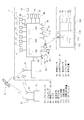
- the schematic side view which shows an autonomous traveling work vehicle, a GPS satellite, and a reference station.
- Control block diagram The figure which shows the state of the work by an autonomous traveling work vehicle and an accompanying traveling work vehicle.
- an autonomous traveling work vehicle 1 capable of autonomous traveling using a satellite positioning system is used as a tractor, and a rotary tiller 24 is mounted as a work implement at the rear of the autonomous traveling work vehicle 1.
- the work vehicle is not limited to a tractor, and may be a combine.
- the work machine is not limited to a rotary tiller. A vertical machine, a mower, a rake, a seeder, a fertilizer, a wagon, etc. It may be.
- the steering wheel 4 is rotated to rotate the front wheels 9 and 9 through the steering device.
- the steering direction of the autonomous traveling work vehicle 1 is detected by the steering sensor 20.
- the steering sensor 20 is composed of an angle sensor such as a rotary encoder, and is disposed at the rotation base of the front wheel 9.
- the detection configuration of the steering sensor 20 is not limited as long as the steering direction is recognized, and the rotation of the steering handle 4 may be detected or the operation amount of the power steering may be detected.
- the detection value obtained by the steering sensor 20 is input to the control device 30.
- a driver's seat 5 is disposed behind the steering handle 4 and a mission case 6 is disposed below the driver's seat 5.
- Rear axle cases 8 and 8 are connected to the left and right sides of the transmission case 6, and rear wheels 10 and 10 are supported on the rear axle cases 8 and 8 via axles.
- the power from the engine 3 is shifted by a transmission (a main transmission or an auxiliary transmission) in the mission case 6 so that the rear wheels 10 and 10 can be driven.
- the transmission is constituted by, for example, a hydraulic continuously variable transmission, and the movable swash plate of a variable displacement hydraulic pump is operated by a transmission means 44 such as a motor so that the transmission can be changed.
- the speed change means 44 is connected to the control device 30.
- the rotational speed of the rear wheel 10 is detected by the vehicle speed sensor 27 and is input to the control device 30 as the traveling speed.
- the vehicle speed detection method and the arrangement position of the vehicle speed sensor 27 are not limited.
- the transmission case 6 houses a PTO clutch, a PTO transmission, and a braking device 46.
- the PTO clutch is turned on and off by a PTO on / off means 45, and the PTO on / off means 45 is connected to the control device 30 to power the PTO shaft. It is possible to control the connection / disconnection.
- the braking device 46 is connected to the control device 30, and can be braked during an operator's operation or automatic traveling.
- the control device 30 includes a CPU (central processing unit), a storage device 30m such as a RAM and a ROM, an interface, and the like, and a program and data for operating the autonomous traveling work vehicle 1 are stored in the storage device 30m.
- a front axle case 7 is supported on a front frame 13 that supports the engine 3, front wheels 9 and 9 are supported on both sides of the front axle case 7, and power from the transmission case 6 can be transmitted to the front wheels 9 and 9. It is configured.
- the front wheels 9, 9 are steered wheels, and can be turned by turning the steering handle 4, and the front wheels 9, 9 can be turned left and right by a steering actuator 40 comprising a power steering cylinder as a steering drive means. It is possible.
- the steering actuator 40 is connected to the control device 30 and is driven by automatic traveling control.
- the controller 30 is connected to an engine controller 60 serving as an engine rotation control means, and the engine controller 60 is connected to an engine speed sensor 61, a water temperature sensor, a hydraulic pressure sensor, and the like so that the state of the engine can be detected.
- the engine controller 60 detects the load from the set rotational speed and the actual rotational speed and controls it so as not to be overloaded, and transmits the state of the engine 3 to the remote operation device 112 described later so that it can be displayed on the display 113. Yes.
- the fuel tank 15 disposed below the step is provided with a level sensor 29 for detecting the fuel level and is connected to the control device 30.
- the display means 49 provided on the dashboard of the autonomous traveling work vehicle 1 has a fuel supply.
- a fuel gauge for displaying the remaining amount is provided and connected to the control device 30. Then, information regarding the remaining amount of fuel is transmitted from the control device 30 to the remote operation device 112, and the remaining fuel amount and workable time are displayed on the display 113 of the remote operation device 112.
- display means 49 for displaying an engine tachometer, a fuel gauge, a hydraulic pressure, etc., a monitor indicating an abnormality, a set value, and the like are arranged.
- a rotary tiller 24 is installed as a work implement on the rear side of the tractor body via the work implement mounting device 23 so as to be able to move up and down to perform the tilling work.
- An elevating cylinder 26 is provided on the transmission case 6, and the elevating arm 26 constituting the work implement mounting device 23 is rotated by moving the elevating cylinder 26 to extend and lower the rotary tiller 24.
- the lift cylinder 26 is expanded and contracted by the operation of the lift actuator 25, and the lift actuator 25 is connected to the control device 30.
- a mobile communication device 33 constituting a satellite positioning system is connected to the control device 30.
- a mobile GPS antenna 34 and a data receiving antenna 38 are connected to the mobile communication device 33, and the mobile GPS antenna 34 and the data receiving antenna 38 are provided on the cabin 11.
- the mobile communicator 33 is provided with a position calculating means for transmitting latitude and longitude to the control device 30 so that the current position can be grasped.
- GPS United States
- high-precision positioning can be performed by using a satellite positioning system (GNSS) such as a quasi-zenith satellite (Japan) or a Glonus satellite (Russia). In this embodiment, GPS is used. explain.
- the autonomous traveling work vehicle 1 includes a gyro sensor 31 for obtaining attitude change information of the airframe, and an orientation sensor 32 for detecting a traveling direction, and is connected to the control device 30.
- the traveling direction can be calculated from the GPS position measurement, the direction sensor 32 can be omitted.
- the gyro sensor 31 detects an angular velocity of a tilt (pitch) in the longitudinal direction of the autonomous traveling work vehicle 1, an angular velocity of a tilt (roll) in the lateral direction of the aircraft, and an angular velocity of turning (yaw).
- the gyro sensor 31 By integrating and calculating the three angular velocities, it is possible to obtain the tilt angle in the front-rear direction and the left-right direction and the turning angle of the body of the autonomous traveling work vehicle 1.
- Specific examples of the gyro sensor 31 include a mechanical gyro sensor, an optical gyro sensor, a fluid gyro sensor, and a vibration gyro sensor.
- the gyro sensor 31 is connected to the control device 30 and inputs information relating to the three angular velocities to the control device 30.
- the direction sensor 32 detects the direction (traveling direction) of the autonomous traveling work vehicle 1.
- a specific example of the direction sensor 32 includes a magnetic direction sensor.
- the direction sensor 32 is connected to the control device 30 and inputs information related to the orientation of the aircraft to the control device 30.
- control device 30 calculates the signals acquired from the gyro sensor 31 and the azimuth sensor 32 by the attitude / azimuth calculation means, and the attitude of the autonomous traveling work vehicle 1 (orientation, forward / backward direction of the body, left / right direction of the body, turning direction) )
- GPS global positioning system
- GPS was originally developed as a navigation support system for aircraft, ships, etc., and is composed of 24 GPS satellites (four on six orbital planes) orbiting about 20,000 kilometers above the sky. It consists of a control station that performs tracking and control, and a user communication device that performs positioning.
- a positioning method using GPS there are various methods such as single positioning, relative positioning, DGPS (differential GPS) positioning, RTK-GPS (real-time kinematics-GPS) positioning, and any of these methods can be used.
- DGPS Differential GPS
- RTK-GPS real-time kinematics-GPS
- RTK-GPS real-time kinematics-GPS positioning is performed by simultaneously performing GPS observations on a reference station whose position is known and a mobile station whose position is to be obtained. Is transmitted in real time, and the position of the mobile station is obtained in real time based on the position result of the reference station.
- a mobile communication device 33 serving as a mobile station, a mobile GPS antenna 34, and a data receiving antenna 38 are arranged in the autonomous traveling work vehicle 1, and a fixed communication device 35 serving as a reference station, a fixed GPS antenna 36, and a data transmission antenna. 39 is disposed at a predetermined position that does not interfere with the work in the field.
- the phase is measured (relative positioning) at both the reference station and the mobile station, and the data measured by the fixed communication device 35 of the reference station is transmitted from the data transmission antenna 39. Transmit to the data receiving antenna 38.
- the mobile GPS antenna 34 disposed in the autonomous traveling work vehicle 1 receives signals from GPS satellites 37, 37. This signal is transmitted to the mobile communication device 33 for positioning. At the same time, signals from GPS satellites 37, 37... Are received by a fixed GPS antenna 36 serving as a reference station, measured by a fixed communication device 35, transmitted to the mobile communication device 33, and the observed data is analyzed and moved. Determine the station location. The position information obtained in this way is transmitted to the control device 30.
- the control device 30 in the autonomous traveling work vehicle 1 includes automatic traveling means for automatically traveling.
- the automatic traveling means receives radio waves transmitted from the GPS satellites 37, 37.
- the position information of the aircraft is obtained at time intervals, the displacement information and the orientation information of the aircraft are obtained from the gyro sensor 31 and the orientation sensor 32, and along the set route R preset by the aircraft based on the position information, the displacement information, and the orientation information.
- the steering actuator 40, the speed change means 44, the lifting / lowering actuator 25, the PTO on / off means 45, the braking device 46, the engine controller 60, and the like are controlled to automatically run and work automatically.
- the positional information on the outer periphery of the field H which becomes a work range is also set in advance by a known method and stored in the storage device 30m.
- the autonomous traveling work vehicle 1 is provided with an obstacle sensor 41 and a camera 42 as obstacle detection means and is connected to the control device 30 so as not to contact the obstacle.
- the obstacle sensor 41 is composed of an infrared sensor or an ultrasonic sensor, and is arranged at the front, side, or rear part of the aircraft and connected to the control device 30, and there are obstacles at the front, side, or rear of the aircraft. If an obstacle is detected, an alarm is issued and control is performed to reduce or stop the traveling speed. Details will be described later.
- the roof of the autonomous traveling work vehicle 1 is mounted with a camera 42 for photographing the front and the work implement and connected to the control device 30.
- the video imaged by the camera 42 is displayed on the display 113 of the remote control device 112 provided in the accompanying traveling work vehicle 100.
- the remote control device 112 sets the set travel route R of the autonomous traveling work vehicle 1, remotely operates the autonomous traveling work vehicle 1, monitors the traveling state of the autonomous traveling work vehicle 1, and the operating state of the work implement. Or work data.
- the operator gets on the accompanying traveling work vehicle 100 to drive and operates the autonomous traveling working vehicle 1 by mounting the remote operation device 112 on the accompanying traveling work vehicle 100.
- the accompanying traveling work vehicle 100 travels while working diagonally behind the autonomous traveling work vehicle 1, and monitors and operates the autonomous traveling work vehicle 1.
- the accompanying traveling work vehicle 100 travels behind the autonomous traveling work vehicle 1 to perform work depending on the work mode, and the present invention is not limited thereto. Since the basic configuration of the accompanying traveling work vehicle 100 is substantially the same as that of the autonomous traveling work vehicle 1, detailed description thereof is omitted.
- the accompanying traveling work vehicle 100 may include a GPS mobile communication device 33 and a mobile GPS antenna 34.
- the remote operation device 112 can be attached to and detached from an operation unit such as a dashboard of the accompanying traveling work vehicle 100 and the autonomous traveling work vehicle 1.
- the remote control device 112 can be operated while attached to the dashboard of the accompanying traveling work vehicle 100, or can be taken out of the accompanying traveling work vehicle 100 to be carried and operated, or attached to the dashboard of the autonomous traveling work vehicle 1.
- the remote operation device 112 can be configured by, for example, a notebook or tablet personal computer. In this embodiment, a tablet computer is used.
- the remote operation device 112 and the autonomous traveling work vehicle 1 are configured to be able to communicate with each other wirelessly, and the autonomous traveling work vehicle 1 and the remote operation device 112 are provided with transceivers 110 and 111 for communication, respectively.
- the transceiver 111 is configured integrally with the remote operation device 112.
- the communication means is configured to be able to communicate with each other via a wireless LAN such as WiFi.
- the remote operation device 112 is provided with a display 113 having a touch panel type operation screen that can be operated by touching the screen on the surface of the housing, and the transceiver 111, the control device 130 (CPU and storage device), a battery, and the like are accommodated in the housing. is doing.
- the autonomous traveling work vehicle 1 can be remotely operated by the remote operation device 112.
- the autonomous traveling work vehicle 1 can be operated for emergency stop, temporary stop, re-start, change of vehicle speed, change of engine speed, raising / lowering of the work machine, turning on / off of the PTO clutch, and the like. That is, the operator can easily operate the autonomous traveling work vehicle by controlling the accelerator actuator, the shifting means 44, the braking device 46, the PTO on / off means 45, etc. from the remote control device 112 via the transceiver 111, the transceiver 110, and the control device 30. 1 can be remotely controlled.
- the display 113 can display surrounding images taken by the camera 42, the state of the autonomous traveling work vehicle 1, the state of work, information on GPS, an operation screen, and the like so that the operator can monitor.
- the state of the autonomous traveling work vehicle 1 includes a traveling state, an engine state, a working machine state, and the like.
- the traveling state includes a shift position, a vehicle speed, a fuel remaining amount, a battery voltage, and the like. Is the engine speed, load factor, etc., and the state of the work machine is the type of work machine, PTO rotation speed, work machine height, etc., which are displayed on the display 113 with numbers, level meters, etc.
- the work status includes: work route (target route or set travel route R), work process, current position, distance to the headland calculated from the process, remaining route, number of processes, current work time, remaining Working hours, etc.
- the remaining paths can be easily recognized by filling the existing work paths from the entire work paths. Further, by displaying the next stroke from the current position with an arrow, it is possible to easily recognize the next stroke such as the turning direction from the current time.
- the information regarding GPS includes longitude and latitude at which the autonomous traveling work vehicle 1 is actually located, the number of satellites supplemented, radio wave reception intensity, an abnormality in the positioning system, and the like.
- the control device 30 includes a mode switching unit 30a and a sensitivity adjustment unit 30b.
- the control device 30 is connected with an obstacle sensor 41 serving as an obstacle detection means, and the sensitivity of the obstacle sensor 41 can be changed by a sensitivity adjustment means 30b.
- the obstacle sensor 41 is composed of an optical sensor or an ultrasonic sensor, and detects an obstacle by detecting light or sound that comes into contact with the obstacle and is reflected.
- the obstacle sensor 41 is provided at the front and rear of the body of the autonomous traveling work vehicle 1.
- the obstacle sensor 41 provided at the front of the body is attached to the front surface of the bonnet 2 and detects an obstacle during forward traveling. I am doing so.
- An obstacle sensor 41 provided at the rear of the machine body is attached to the rear surface of the fender so as to detect an obstacle during reverse travel.
- the sensitivity adjustment of the obstacle sensor 41 attached to the front of the machine body will be described with reference to FIG.
- the obstacle sensor 41 detects whether there is an obstacle such as a person or an object in a predetermined detection range K in front of the autonomous traveling work vehicle 1.
- the detection range K is adjusted by the sensitivity adjusting means 30b according to the traveling position in the setting work area. That is, the sensitivity adjustment means 30b adjusts the sensitivity of the obstacle sensor 41 so that the sensitivity is high inside the setting work area and low outside the setting work area.
- the detection range K of the obstacle sensor 41 is wide at the central portion in the field H as a setting work area, and becomes smaller as the outer periphery of the field H is approached.
- the detection range K is fan-shaped and has a radial distance (detection distance) L and a left-right angle ⁇ .
- the detection distance L is the maximum length L1
- the left / right detection width D is the maximum left / right detection width D1.
- the detection distance L is gradually shortened (L2), and obstacles outside the set work area are not detected.
- the obstacle sensor 41 is adjusted by the sensitivity adjusting means 30b so that the sensitivity decreases as it approaches the field edge. Since this setting work area is set using a satellite positioning system before starting work, how much is this map data and the set travel route R set before starting work to the field end (around field H). When the distance from the front end of the autonomous traveling work vehicle 1 to the field end is equal to or less than the maximum length L1, the sensitivity is set so that the detection range K of the obstacle sensor 41 is the distance to the field end. Adjustment is performed by the adjusting means 30b. Further, the left / right detection width D is also made narrow when traveling on the heel so that obstacles outside the set work area are not detected. However, the sensitivity adjustment may be corrected by changing the reference level of the detected value, and is not limited.
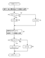
- Sensitivity adjustment control will be described with reference to the flowchart of FIG.
- the distance A from the front end of the machine body to the front field edge is calculated (S1), and the distance A to the field edge is compared with the maximum detection distance L1 of the obstacle sensor 41 (S2). If the distance A to the field edge is longer than the maximum detection distance L1, the detection distance L is maintained at the maximum detection distance L1 (S3), and the process proceeds to step S4. If the distance A is short, the distance A to the field edge is set.
- the sensitivity is adjusted by the sensitivity adjusting means 30b so as to be the detection distance L (S5), and the process proceeds to step S4.
- step S4 the distance B from the aircraft center to the side edge is calculated (S4).
- the distance B to the heel and the left and right maximum detection width D1 are compared (S6). If the distance B to the heel is longer than the left and right maximum detection width D1, the left and right detection width D is set as the left and right maximum detection width D1. (S7) When the distance B to the heel is shorter than the left and right maximum detection width D1, the left and right detection width D is set to the distance B to the heel (S8).
- the actual work area is not rectangular, but is distorted and trapezoidal, so that a certain tolerance can be provided.
- the detection range K by the obstacle sensor 41 is gradually reduced as it approaches the field edge, but may be reduced stepwise. Further, when the autonomous traveling work vehicle 1 enters a predetermined range (for example, a headland turning region) near the outer periphery of the field H, the detection range K can be reduced to a predetermined small range.
- the autonomous traveling work vehicle including the position calculating means for positioning the position of the aircraft using the satellite positioning system and the control device 30 that automatically travels and works along the set traveling route R.
- an obstacle sensor 41 serving as an obstacle detection means for detecting whether or not an obstacle exists around the autonomous traveling work vehicle 1 and a sensitivity adjustment means 30b for adjusting the sensitivity of the obstacle sensor 41 are provided.
- the sensitivity is adjusted by the sensitivity adjusting means 30b so that the sensitivity of the obstacle sensor 41 is high inside the setting work area and low outside the setting work area. Attention is urged and the detection range K is not detected outside the field H, so that false detection can be reduced and workability can be improved.
- control device 30 adjusts the sensitivity by the sensitivity adjusting means 30b so that the detection range K by the obstacle sensor 41 is within the set work area, so that the control device 30 can be applied to a fence, a farm field H, a road or the like outside the work range. Even if there is an obstacle, the obstacle sensor 41 determines that the obstacle is an obstacle and does not issue an alarm or stop the work or running, so that the detection accuracy can be improved and the work can be performed even on the verge. Can be prevented.
- control device 30 adjusts the sensitivity by the sensitivity adjusting means 30b so that the detection range K is wide at the center of the work area and becomes smaller as it approaches the outer periphery of the work area, it is sensitive in the set work area. Obstacles in response to the above can be reliably detected, and even when approaching the field edge, obstacles outside the set work area are not detected, and the work can be reliably performed to the field edge without stopping traveling.
- control device 30 is connected with an optical sensor 71, an outside air temperature sensor 72, and a rain detection sensor 73 as environment recognition means, and according to detection values from the light sensor 71, the outside air temperature sensor 72, and the rain detection sensor 73. Therefore, the sensitivity of the obstacle sensor 41 is changed by the sensitivity adjusting means 30b according to the weather so that no false detection occurs, and the detection accuracy of the obstacle sensor 41 can be improved regardless of the weather. I am doing so.
- the control device 30 switches to the direct sunlight mode by the mode switching means 30a and decreases the sensitivity by the sensitivity adjustment means 30b.
- the control device 30 switches to the low temperature mode by the mode switching unit 30a and increases the sensitivity of the obstacle sensor 41 by the sensitivity adjustment unit 30b. In this way, human detection accuracy is improved.
- the obstacle sensor 41 may detect raindrops. Therefore, when rain is detected by the rain detection sensor 73, the control device 30 reduces the sensitivity by the sensitivity adjustment means 30b so as to eliminate the influence of the rain. Further, when the detected value from the rain detection sensor 73 is equal to or higher than the set value, the operation is impossible, and when the detected value of the outside air temperature sensor 72 is equal to or lower than the set temperature and the rain is detected, snow is detected. Since it can be determined that it is falling and work cannot be performed, work is not allowed. However, in order to recognize the environment (weather), the optical sensor 71, the outside air temperature sensor 72, and the rain detection sensor 73 are used as the environment recognizing means.
- the operator may directly input the illuminance, the outside air temperature, and the rainfall. .
- the weather information may be directly read into the control device 30 via the Internet. Note that since information from the Internet is in a wide range, it may not rain in an actual place, and the weather forecast may be off, so correction is preferably performed by detection from the rain detection sensor 73.
- the mode switching means 30a switches to the headlight mode (or night mode), and when a detected value greater than or equal to the set illuminance is acquired, the filter is passed through. Only detection values below a predetermined value are acquired, and disturbances due to headlights and night illumination are removed.
- the storage device 30m provided in the control device 30 stores the work time, the set work area, the work environment (day and night or weather), and the sensitivity adjustment history at that time, and can be displayed arbitrarily. . In this way, before starting work, search whether there is a match between the current rainfall conditions and the past work temperature conditions, and if there is a match, read the data at that time and change the sensitivity. It is possible to perform efficient work by examining whether the adjustment has been performed properly and adopting an appropriate sensitivity adjustment.
- the obstacle sensor 41 detects an obstacle and issues an alarm, but there is actually no obstacle (hereinafter referred to as “false alarm”).
- a process performed by the control device 30 when the obstacle sensor 41 does not detect and does not issue an alarm although it exists hereinafter referred to as “missing information”.
- the remote control device 112 is provided with a false alarm switch 76 as a false alarm notification means (FIG. 2), and the false alarm switch 76 is connected to the control device 130 of the remote controller 112.
- the place where the misinformation switch 76 is provided is not limited to the remote control device 112, and may be disposed in the control unit in the vicinity of the driver's seat of the accompanying traveling work vehicle 100 or the autonomous traveling work vehicle 1.
- the obstacle sensor 41 When the obstacle sensor 41 detects an obstacle, an alarm sound is emitted from the speaker 51 as an alarm means, and the display means 49 and the display 113 indicate that an obstacle exists. However, although the obstacle sensor 41 detects the obstacle and issues an alarm, there is a case where the obstacle is not recognized when the operator actually confirms. At this time, the operator turns on the false alarm switch 76. When this error report switch 76 is turned on, the control device 130 determines that the error has occurred, and the control device 130 of the remote control device 112 displays the error information on the display 113. At the same time, the transmitter / receiver 111 and the autonomous traveling work vehicle 1 The alarm from the speaker 51 is canceled via the transceiver 110 and the control device 30. In this way, useless alarms are prevented and noise caused by alarm sounds is eliminated.
- the alarm means is not limited to the speaker 51, but can be a buzzer, a horn, or the like.
- the operation is continued, and the obstacle sensor 41 detects an obstacle and issues an alarm. If there is actually no obstacle, the operator turns on the false alarm switch 76 and displays the alarm in the same manner as described above. To release.
- the sensitivity adjustment means 30b lowers the sensitivity of the obstacle sensor 41 by a predetermined level and does not detect it sensitively. Like that. However, the level for reducing the sensitivity can be arbitrarily set. In this way, sensitivity adjustment is automatically performed to prevent frequent false alarms.
- the obstacle sensor 41 is determined to be faulty, and is displayed on the display means 49 and the display 113 so that the operator can recognize the fault, and at the same time, a repair request for a store or a service station can be requested through an internet line or the like. Is notified that a failure has occurred.
- the sensitivity of the obstacle sensor 41 is lowered by a predetermined level (S111), and the false alarm count n is set to 0 (reset) (S112).
- Flag 1 is set (S113) and the process proceeds to step S102.
- step S109 since the sensitivity is lowered when the flag is 1, the process proceeds to step S114, and it is determined whether the false alarm count n exceeds the second set number N2. If it does not exceed, the process proceeds to step S102. If it exceeds, the obstacle sensor 41 determines that it is out of order, displays a failure (S115), and notifies the dealer (S116).
- the remote control device 112 is provided with a misreport switch 77 as a misreport notification means, and the misreport switch 77 is connected to the control device 130.
- the remote operation device 112 is provided with an emergency stop button 78 for emergency stop of the autonomous traveling work vehicle 1 and connected to the control device 130.
- the location where the unreported switch 77 and the emergency stop button 78 are provided is not limited to the remote control device 112, and may be disposed in the control section near the driver's seat of the accompanying traveling work vehicle 100 or the autonomous traveling work vehicle 1. . In the emergency stop, the engine 3 is stopped so that neither traveling nor work can be performed.
- the obstacle sensor 41 Even when the operator visually recognizes an obstacle in the detection range by the obstacle sensor 41 in front of the autonomous traveling work vehicle 1 (rearward when moving backward) during the forward traveling work, the obstacle sensor 41 does not detect the obstacle, and an alarm is given. If neither is displayed nor displayed, the operator turns on the unreported switch 77. When the unreport switch 77 is turned on, the control device 130 of the remote control device 112 displays that the report 113 is unreported, and at the same time, the transceiver 111, the transceiver 110 of the autonomous traveling work vehicle 1, An alarm from the speaker 51 is issued via the control device 30 to stop running and work. Thus, collision with an obstacle can be avoided. In addition, even when an obstacle is present, the obstacle sensor 41 does not detect and does not issue an alarm, and when the emergency stop button 78 is pressed, the control device 130 also determines that there is no report.
- the sensitivity adjustment means 30b increases the sensitivity of the obstacle sensor 41 by a predetermined level to make it sensitive.
- the level for increasing the sensitivity can be arbitrarily set. In this way, sensitivity adjustment is automatically performed, and frequent misreporting can be prevented.
- the control for increasing the sensitivity of the obstacle sensor 41 may be performed a plurality of times. In this way, failure determination is automatically performed and failure notification is automatically performed.
- step S202 If it is less than N3, the process returns to step S202, and when the number of missed reports m exceeds the third set number N3, the sensitivity of the obstacle sensor 41 is increased by a predetermined level (S207), the number of missed reports m is reset (S208), and flag 1 (S209), the process proceeds to step S202.
- step S205 if the flag is 1, the sensitivity has been increased. Therefore, the process proceeds to step S210, and it is determined whether the number of missed reports m has exceeded the fourth set number N4. If it does not exceed, the process proceeds to step S202. If it exceeds, the obstacle sensor 41 determines that it is out of order, displays it (S211), and notifies the dealer (S211).
- the human detection sensor 70 includes a distance sensor 74 that detects the distance between the obstacle sensor 41 and the camera 42 and the person, an infrared sensor, and the like.
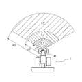
- the control device 30 When the human detection sensor 70 detects a person within the first setting range E1 (FIG. 4) while performing an autonomous traveling in the field H, which is a preset setting work area, the control device 30 The first alarm sound is emitted from the speaker 51 serving as the first stage alarm and displayed on the display means 49 and the display 113 of the remote control device 112, and at the same time, the vehicle is controlled to stop traveling. That is, when a person jumps out from the autonomous traveling work vehicle 1 into the first setting range E1, an emergency stop is automatically made and a first alarm sound is generated to indicate that the emergency stop has occurred on the display means 49 or the display 113.
- the first alarm sound is a relatively loud sound having a high frequency and sound that can be heard well around.
- the engine 3 is stopped by the engine controller 60 or the transmission means 44 is braked as neutral, and the method is not limited. Further, when the vehicle is not traveling outside the field or autonomously (steered by the operator) or is traveling on the road, the collision avoidance control based on the human detection is not performed, and another collision avoidance control is performed.
- the setting range is a fan shape for easy explanation, but is not limited, and may be a square, a triangle, a circle, or the like. It is also possible to provide a speaker 151 on the remote operation device 112 and connect it to the control device 130 of the remote operation device 112 so that an alarm sound is emitted from the speaker 151 at the same time when the alarm is issued.
- the first set range E1 is a sector having a radius of the longest distance e1 from when a person is detected until the movement of the airframe stops when the autonomous traveling work vehicle 1 travels at a low speed (for example). Range.
- the radius length e1 that is the longest distance is the free running distance from when the human detection sensor 70 detects a person who has entered the first setting range E1 and when a stop signal is issued and the braking device and the shifting means are activated.
- the longest distance is the sum of the distance from braking to slipping and stopping.
- the first setting range E1 is a range in which a collision may occur even when an emergency stop is detected by detecting an intruder when the vehicle is traveling at a work speed.
- the control device 30 causes the second setting device E2 to detect the person.
- a second alarm sound is emitted from the speaker 51 serving as a stage alarm and displayed on the display means 49 and the display 113 of the remote control device 112 to control the traveling speed to be reduced. That is, when a person enters the second setting range E2 farther than the first setting range E1, the speed change means 44 is automatically shifted to the deceleration side (in the case of traveling at the first speed, the engine controller 60 rotates the engine). Reduce the number), reduce the running speed and emit a second warning sound.
- the second alarm sound is lower in volume and lower in frequency than the first alarm sound, and is less urgent than the first setting range E1, but can easily recognize that the autonomous traveling work vehicle 1 is approaching. Yes.
- the alarm sound may be an intermittent sound.
- the second setting range E2 is a range farther than the first setting range E1 but closer to the third setting range E3, and the third setting range E3 is the longest length e3 at which the human detection sensor 70 can detect a person.
- the autonomous mobile work vehicle 1 From the fan-shaped range with a radius of ⁇ , the autonomous mobile work vehicle 1 detects a person when the sub-shifting vehicle 1 is traveling at a high speed (for example, the sub-speed is a high speed or a set speed faster than the low speed), and then the airframe.
- This is a range excluding a fan-shaped range having a radius of the longest distance e2 until the movement stops.
- the person detection sensor 70 detects a person who has entered the second setting range E2 and makes an emergency stop, the person detection sensor 70 is set in a range that can be stopped with a margin without colliding with a person. Therefore, when traveling at a working speed, when a person is detected in the second setting range E2, the person who enters the second setting range E2 is dangerous by decelerating and generating a second alarm sound. The collision can be easily avoided by feeling. Note that when a person enters the first set range E1, an emergency stop naturally occurs, and a collision is avoided.
- the control device 30 causes the third device A third alarm sound is emitted from the speaker 51 serving as a stage alarm to alert a person. That is, when a person enters the third setting range E3 far from the second setting range E2 from the autonomous traveling work vehicle 1, the autonomous traveling working vehicle 1 is approaching the person by the third alarm. It is made to recognize.
- the third alarm sound may be any sound that can be heard to approach the speaker 51 or can be alerted by the sound of the horn.
- the traveling speed may be decelerated, the engine speed may be decreased for decelerating, and the decelerating speed of the second setting range E2 is slower than the speed of the third setting range E3.
- the third setting range E3 is a range obtained by removing the first setting range E1 and the second setting range E2 from the range in which the human detection sensor 70 can detect a person. That is, it is a range farther than the second setting range E2 and capable of detecting a person. In other words, it is a range in which a person can perform an avoidance operation with a margin.
- the first setting range E1, the second setting range E2, and the third setting range E3 may be changed according to the traveling speed. That is, as the traveling speed increases, e1, e2, and e3 can be adjusted to be longer (the first setting range E1, the second setting range E2, and the third setting range E3 are widened).
- the inertial force is calculated from the weight of the work machine (adding fertilizer, medicine, or luggage when loaded) or the body, and e1, e2, e3 are lengthened as the inertial force increases.
- the aircraft is provided with an inclination sensor, and e1, e2, e3 are lengthened as the downward inclination angle at which the aircraft is located is increased, and is shortened as the inclination is increased.
- the first-stage alarm to the third-stage alarm may be lighted or flashed with a light (flash light) or a direction indicator.
- the urgency level (risk level) can be determined.
- the brightness of the first stage alarm is increased or the number of blinks is increased.
- the warning sound is a different volume, tone, intermittent sound or voice / music at each stage so that the urgency level can be determined.
- the first stage alarm is set to a louder tone. The alarm sound may be selectable.
- the human detection is canceled after the human detection sensor 70 detects a person, the first-stage alarm to the third-stage alarm are canceled and a release sound is emitted simultaneously and displayed on the display means 49 and the display 113. It doesn't matter.
- the situation at this time for example, the position at the time of alarm, date and time, video, etc., is stored in the storage device 30m so that it can be taken out as a data, and is made into a database with a host computer, etc. You may make it available to.
- the control device 30 issues an alarm and alerts the person.
- the worker who recognizes that the work vehicle 1 is operating is doing another agricultural work in the field H, it can be easily recognized that the autonomous traveling work vehicle 1 is approaching, The avoidance action can be appropriately performed.
- the human detection sensor 70 detects a person in any one of the first setting range E1, the second setting range E2, and the third setting range E3, an alarm is generated and displayed on the display means. And the display is made different in each range. Therefore, a person who has entered a range that can be detected by the human detection sensor 70 can easily recognize how close the autonomous traveling work vehicle is, and can appropriately perform a collision avoidance action according to each range.
- a release switch 75 is provided as a means for releasing the alarm and display, and is connected to the control device 30 so that the alarm and display can be arbitrarily released. Prevents alarms from continuing to sound because they are within the setting range E1, or alarms continue to sound even if people in the third setting range E3 are taking collision avoidance actions, When an alarm is issued, the useless alarm can be stopped to prevent noise.
- the release switch 75 is provided in a control unit such as a dashboard of the autonomous traveling work vehicle 11 or the accompanying traveling work vehicle 100 and the remote control device 112.
- the camera 42 can also detect obstacles, and the image captured by the camera 42 is subjected to image processing by the control device 30 to detect animals other than humans. Control so as not to decelerate or warn. In other words, animals such as dogs, cats and birds usually escape when the autonomous traveling work vehicle 1 approaches, so there is almost no possibility of collision, but rather the human detection sensor 70 reacts because it approaches the autonomous traveling work vehicle 1. As a result, the autonomous traveling work vehicle 1 may be slowed down or stopped to hinder work. Therefore, when the image processing from the camera 42 recognizes that an animal has entered one of the first setting range E1, the second setting range E2, or the third setting range E3, the signal from the human detection sensor 70 is canceled. The autonomous traveling work vehicle 1 is not decelerated or stopped.
- the human detection sensor 70 detects an animal, the transmission device and the braking device are not operated, the alarm device is operated, the headlight is turned on, and threatened.
- the human detection sensor 70 detects an animal, an image is displayed on the display means 49 or the display 113, and a transmission or a braking device is operated by an operator's operation.
- the image processing by the control device 30 of the image taken by the camera 42 detects a moving object. Then, moving objects are highlighted, and if an object that is larger than a certain size and smaller than a human is moving, it is judged as an animal. In the case of the size of a small child, the operator shall judge.
- the present invention can be used for a construction machine, an agricultural work vehicle, or the like in which a work vehicle uses a satellite positioning system to perform work on a predetermined farm field or the like.
Landscapes
- Engineering & Computer Science (AREA)
- Physics & Mathematics (AREA)
- Radar, Positioning & Navigation (AREA)
- Remote Sensing (AREA)
- Aviation & Aerospace Engineering (AREA)
- General Physics & Mathematics (AREA)
- Automation & Control Theory (AREA)
- Mechanical Engineering (AREA)
- Life Sciences & Earth Sciences (AREA)
- Acoustics & Sound (AREA)
- Electromagnetism (AREA)
- Soil Sciences (AREA)
- Environmental Sciences (AREA)
- Computer Vision & Pattern Recognition (AREA)
- Multimedia (AREA)
- Guiding Agricultural Machines (AREA)
- Control Of Position, Course, Altitude, Or Attitude Of Moving Bodies (AREA)
- Business, Economics & Management (AREA)
- Health & Medical Sciences (AREA)
- Artificial Intelligence (AREA)
- Evolutionary Computation (AREA)
- Game Theory and Decision Science (AREA)
- Medical Informatics (AREA)
Abstract
Description
本発明は、前記人検知センサが、第一設定範囲、第二設定範囲、第三設定範囲の何れか範囲で人を検知すると、警報を発して表示手段に表示するとともに、該警報及び表示はそれぞれの範囲で異なるようにしたものである。
本発明は、前記制御装置には警報及び表示解除手段が接続され、任意に警報及び表示を解除可能としたものである。
ジャイロセンサ31は自律走行作業車両1の機体前後方向の傾斜(ピッチ)の角速度、機体左右方向の傾斜(ロール)の角速度、および旋回(ヨー)の角速度、を検出するものである。該三つの角速度を積分計算することにより、自律走行作業車両1の機体の前後方向および左右方向への傾斜角度、および旋回角度を求めることが可能である。ジャイロセンサ31の具体例としては、機械式ジャイロセンサ、光学式ジャイロセンサ、流体式ジャイロセンサ、振動式ジャイロセンサ等が挙げられる。ジャイロセンサ31は制御装置30に接続され、当該三つの角速度に係る情報を制御装置30に入力する。
GPSは、元来航空機・船舶等の航法支援用として開発されたシステムであって、上空約二万キロメートルを周回する二十四個のGPS衛星(六軌道面に四個ずつ配置)、GPS衛星の追跡と管制を行う管制局、測位を行うための利用者の通信機で構成される。
GPSを用いた測位方法としては、単独測位、相対測位、DGPS(ディファレンシャルGPS)測位、RTK-GPS(リアルタイムキネマティック-GPS)測位など種々の方法が挙げられ、これらいずれの方法を用いることも可能であるが、本実施形態では測定精度の高いRTK-GPS測位方式を採用し、この方法について図1、図2より説明する。
GPSに関する情報は、自律走行作業車両1の実位置となる経度や緯度、衛星の補足数や電波受信強度や測位システムの異常等である。
制御装置30には、モード切替手段30aと感度調整手段30bとを備える。
制御装置30には、障害物検知手段となる障害物センサ41が接続され、障害物センサ41の感度は感度調整手段30bにより変更可能としている。障害物センサ41は光センサまたは超音波センサで構成され、障害物に当接して反射した光または音を検出することで障害物を検出するようにしている。
障害物センサ41は自律走行作業車両1の前方の所定の検知範囲Kに人や物等の障害物が存在しないか検知する。前記検知範囲Kは設定作業エリア内の走行位置に応じて感度調整手段30bにより調整される。つまり、障害物センサ41の感度を、設定作業エリア内は高く、設定作業エリア外は低くなるように感度調整手段30bにより感度を調整する。設定作業エリアを圃場Hとすることで、圃場H内を走行するときには小さな障害物でも敏感に反応して、オペレータに注意を促し、圃場H外を検知しているときには、障害物が存在しても検知しないようにしている。
但し、環境(天候)を認識するために、環境認識手段として光センサ71、外気温度センサ72及び降雨検知センサ73を用いているが、オペレータが照度や外気温度や雨量を直接入力してもよい。また、インターネットを介して天気情報を直接制御装置30に読み込むように構成してもよい。なお、インターネットからの情報は広い範囲であるため、実際の場所では雨が降らないこともあり、天気予報が外れる場合もあるので、降雨検知センサ73からの検出で補正することが好ましい。
前記遠隔操作装置112には、誤報通知手段としての誤報スイッチ76が設けられ(図2)、誤報スイッチ76は遠隔操作装置112の制御装置130と接続されている。但し、誤報スイッチ76を設ける場所は遠隔操作装置112に限定するものではなく、随伴走行作業車両100や自律走行作業車両1の運転席近傍の操縦部に配置してもよい。
まず、フラグを0とし、誤報回数n=0とする(S101)。障害物センサ41が障害物を検知したか判断する(S102)。障害物センサ41が障害物を検知すると警報を発して表示する(S103)。障害物がなくなった、あるいは、解除スイッチ75が操作されているか判断し(S104)、この警報および表示が解除されると(S105)、ステップS102に戻る。ステップS104で誤検知であると警報を解除せず誤報スイッチ76を押すので、誤報スイッチ76が操作されたか判断する(S106)。操作されないとステップS104に戻り、操作されると警報および表示を解除し(S107)、誤報回数nをn+1とする(S108)。初めての誤報であればN=1となる。次に、フラグが1であるか判断する。つまり、感度を下げたときにフラグを立てるようにするので、フラグが1かどうか判断し(S109)、1でない(感度を下げていない通常検知)場合は、誤報回数nが第一設定数N1以上か判断する(S110)。N1未満の場合ステップS102に戻り、誤報回数nが第一設定数N1以上となると障害物センサ41の感度を所定レベル下げて(S111)、誤報回数nを0と(リセット)し(S112)、フラグ1を立てて(S113)ステップS102に移行する。
前記遠隔操作装置112には、失報通知手段としての失報スイッチ77が設けられ、失報スイッチ77は制御装置130と接続されている。また、遠隔操作装置112には自律走行作業車両1を緊急停止させるための緊急停止ボタン78が設けられて制御装置130と接続されている。但し、失報スイッチ77及び緊急停止ボタン78を設ける場所は遠隔操作装置112に限定するものではなく、随伴走行作業車両100や自律走行作業車両1の運転席近傍の操縦部に配置してもよい。なお、緊急停止はエンジン3を停止させて走行も作業もできないようにすることとする。
まず、フラグを0とし、失報回数m=0とする(S201)。オペレータが失報スイッチ77(あるいは緊急停止ボタン78)を操作したか判断する(S202)。失報スイッチ77が操作されると警報および表示を行い停止する(S203)、失報回数mをm+1とする(S204)。次にフラグが1であるか、つまり感度を上げたか判断し(S205)、1でない(感度を上げていない)場合は、失報回数mが第三設定数N3以上か判断する(S206)。N3未満の場合ステップS202に戻り、失報回数mが第三設定数N3以上となると障害物センサ41の感度を所定レベル上げて(S207)、失報回数mをリセットし(S208)、フラグ1を立てて(S209)ステップS202に移行する。
但し、第一設定範囲E1、第二設定範囲E2、第三設定範囲E3は走行速度に応じてその範囲を変更してもよい。つまり、走行速度が速いほど、e1、e2、e3を長くする(第一設定範囲E1、第二設定範囲E2、第三設定範囲E3を広くする)ように調整することもできる。また、慣性力や傾斜角度に応じて前記各範囲を変更してもよい。つまり、作業機(肥料や薬剤や荷物を搭載している場合には加算する)や本体の重量から慣性力を計算し、その慣性力が大きいほどe1、e2、e3を長くする。また、機体に傾斜センサを備え、機体が位置する下り方向の傾斜角が大きいほどe1、e2、e3を長くし、登り傾斜ほど短くする。
また、第一段階警報~第三段階警報は、音に加えてライト(フラッシュライト)や方向指示器等、光による点灯や点滅等を行ってもよい。この場合、各段階で異なる光の強さや異なる点滅が行われて緊急度(危険度)が判るようにする。例えば、第一段階警報ほど輝度を大きくしたり、点滅回数を多くしたりする。
また、警報音は各段階で、異なる音量や音色や断続音または音声・音楽とし、緊急度が判るようにする。例えば、第一段階警報ほど大きな高い音色の音とする。なお、該警報音は選択可能としてもよい。
更に、人検知センサ70が人を検知した後に、人検知が解除された時、第一段階警報~第三段階警報の解除を行と同時に、解除音を発し、表示手段49及びディスプレイ113に表示しても構わない。そして、この時の状況、例えば警報時の位置や日時や映像等を記憶装置30mに記憶し、データとして取り出せるようにし、ホストコンピュータ等でデータベース化し、警報方法や危険回避の改善、事故の証拠等に利用できるようにしてもよい。
30 制御装置
30m 記憶装置
49 表示手段
70 人検知センサ
112 遠隔操作装置
113 ディスプレイ
Claims (5)
- 衛星測位システムを利用して機体の位置を測位する位置算出手段と、設定した走行経路に沿って自動的に走行及び作業をさせる制御装置とを備えた自律走行作業車両において、自律走行作業車両に人検知センサを設けて制御装置と接続し、設定作業地内で自律走行させながら作業をしているときに、人検知センサが、作業速度で走行しているときに、人の侵入を検知してから機体の移動が停止するまでの最長距離となる第一設定範囲内で人を検知すると、制御装置は走行を停止するように制御することを特徴とする自律走行作業車両。
- 前記人検知センサが、第一設定範囲よりも遠く、自律走行作業車両が前記走行速度よりも設定速度速く走行しているときに停止できる最長距離の第二設定範囲内で人を検知すると、前記制御装置は走行速度を減速するように制御することを特徴とする請求項1に記載の自律走行作業車両。
- 前記人検知センサが、第二設定範囲よりも遠い第三設定範囲で人を検知すると、前記制御装置は警報を発し、人に対して注意喚起を行うことを特徴とする請求項1または請求項2に記載の自律走行作業車両。
- 前記人検知センサが、第一設定範囲、第二設定範囲、第三設定範囲の何れかの範囲で人を検知すると、前記制御装置は警報を発して表示手段に表示するとともに、該警報及び表示はそれぞれの範囲で異なるようにしたことを特徴とする請求項1乃至請求項3のいずれか1項に記載の自律走行作業車両。
- 前記制御装置には警報及び表示解除手段が接続され、任意に警報及び表示を解除可能としたことを特徴とする請求項1乃至請求項4のいずれか1項に記載の自律走行作業車両。
Priority Applications (5)
| Application Number | Priority Date | Filing Date | Title |
|---|---|---|---|
| KR1020167030196A KR20160138542A (ko) | 2014-03-28 | 2015-03-26 | 자율 주행 작업 차량 |
| CN201580017306.0A CN106164800A (zh) | 2014-03-28 | 2015-03-26 | 自主行驶作业车辆 |
| JP2016510476A JPWO2015147149A1 (ja) | 2014-03-28 | 2015-03-26 | 自律走行作業車両 |
| EP15770095.6A EP3125060A1 (en) | 2014-03-28 | 2015-03-26 | Autonomously traveling work vehicle |
| US15/129,559 US20170135277A1 (en) | 2014-03-28 | 2015-03-26 | Autonomously traveling work vehicle |
Applications Claiming Priority (2)
| Application Number | Priority Date | Filing Date | Title |
|---|---|---|---|
| JP2014-070105 | 2014-03-28 | ||
| JP2014070105 | 2014-03-28 |
Publications (1)
| Publication Number | Publication Date |
|---|---|
| WO2015147149A1 true WO2015147149A1 (ja) | 2015-10-01 |
Family
ID=54195656
Family Applications (1)
| Application Number | Title | Priority Date | Filing Date |
|---|---|---|---|
| PCT/JP2015/059337 Ceased WO2015147149A1 (ja) | 2014-03-28 | 2015-03-26 | 自律走行作業車両 |
Country Status (6)
| Country | Link |
|---|---|
| US (1) | US20170135277A1 (ja) |
| EP (1) | EP3125060A1 (ja) |
| JP (1) | JPWO2015147149A1 (ja) |
| KR (1) | KR20160138542A (ja) |
| CN (1) | CN106164800A (ja) |
| WO (1) | WO2015147149A1 (ja) |
Cited By (32)
| Publication number | Priority date | Publication date | Assignee | Title |
|---|---|---|---|---|
| WO2017110116A1 (ja) * | 2015-12-25 | 2017-06-29 | 株式会社クボタ | 作業車 |
| JP2017112962A (ja) * | 2015-12-25 | 2017-06-29 | 株式会社クボタ | 作業車 |
| JP2017123829A (ja) * | 2016-01-15 | 2017-07-20 | 株式会社クボタ | 圃場作業車両 |
| EP3202246A1 (de) * | 2016-01-25 | 2017-08-09 | Amazonen-Werke H. Dreyer GmbH & Co. KG | Landwirtschaftliche maschine |
| JP2018186760A (ja) * | 2017-05-08 | 2018-11-29 | 井関農機株式会社 | 作業車両 |
| JP2019004853A (ja) * | 2017-06-28 | 2019-01-17 | 株式会社クボタ | 作業車 |
| JP2019062793A (ja) * | 2017-09-29 | 2019-04-25 | 井関農機株式会社 | コンバインの制御システム |
| JP2019157407A (ja) * | 2018-03-08 | 2019-09-19 | 日立建機株式会社 | 転圧機械 |
| JP2019168888A (ja) * | 2018-03-23 | 2019-10-03 | ヤンマー株式会社 | 障害物検知システム |
| JP2019175049A (ja) * | 2018-03-28 | 2019-10-10 | ヤンマー株式会社 | 作業車両の自動走行装置 |
| JP2019170271A (ja) * | 2018-03-28 | 2019-10-10 | ヤンマー株式会社 | 作業車両 |
| JP2019170309A (ja) * | 2018-03-29 | 2019-10-10 | ヤンマー株式会社 | 作業車両 |
| JP2020058384A (ja) * | 2016-01-15 | 2020-04-16 | 株式会社クボタ | 圃場作業車両 |
| JP2020131862A (ja) * | 2019-02-18 | 2020-08-31 | トヨタ自動車株式会社 | 車両制御装置 |
| JP2020175890A (ja) * | 2020-06-30 | 2020-10-29 | 株式会社クボタ | 作業車 |
| WO2021010297A1 (ja) * | 2019-07-12 | 2021-01-21 | ヤンマーパワーテクノロジー株式会社 | 自動走行システム |
| JP2021006052A (ja) * | 2020-09-30 | 2021-01-21 | 井関農機株式会社 | 作業車両 |
| JP2021106557A (ja) * | 2019-12-27 | 2021-07-29 | 株式会社クボタ | 作業支援システム |
| US11080997B2 (en) * | 2016-04-28 | 2021-08-03 | Sumitomo Electric Industries, Ltd. | Recommended traveling speed provision program, travel support system, vehicle control device, and automatic traveling vehicle |
| JP2021168695A (ja) * | 2019-12-27 | 2021-10-28 | 株式会社クボタ | 圃場作業車両 |
| JP2021171905A (ja) * | 2020-04-30 | 2021-11-01 | 東京ロボティクス株式会社 | ロボット制御装置、方法、及びプログラム |
| JP2022057867A (ja) * | 2020-09-30 | 2022-04-11 | 一般財団法人宇宙システム開発利用推進機構 | 衝突防止システム、衝突防止装置および衝突防止方法 |
| WO2022118772A1 (ja) | 2020-12-02 | 2022-06-09 | ヤンマーホールディングス株式会社 | 自動走行システム、自動走行方法、及び自動走行プログラム |
| WO2022118771A1 (ja) * | 2020-12-02 | 2022-06-09 | ヤンマーホールディングス株式会社 | 自動走行システム、自動走行方法、及び自動走行プログラム |
| EP4011818A1 (en) | 2020-12-14 | 2022-06-15 | Kabushiki Kaisha Toyota Jidoshokki | Engine-type industrial vehicle |
| WO2022130756A1 (ja) * | 2020-12-18 | 2022-06-23 | 株式会社小松製作所 | 複数の作業機械を制御するためのシステム及び方法 |
| JP2023042915A (ja) * | 2021-09-15 | 2023-03-28 | 株式会社アマダ | 車両走行支援装置、自動搬送装置、および車両走行支援方法 |
| JPWO2023073803A1 (ja) * | 2021-10-26 | 2023-05-04 | ||
| JP2023181369A (ja) * | 2019-02-08 | 2023-12-21 | コベルコ建機株式会社 | 建設機械の障害物検出装置 |
| WO2024142659A1 (ja) * | 2022-12-26 | 2024-07-04 | 株式会社クボタ | 作業車両 |
| JP2024123692A (ja) * | 2023-03-01 | 2024-09-12 | 株式会社デンソー | 移動体制御装置 |
| EP4283053A4 (en) * | 2021-03-26 | 2024-12-25 | Komatsu Ltd. | WORKING MACHINE AND METHOD FOR CONTROLLING THE WORKING MACHINE |
Families Citing this family (58)
| Publication number | Priority date | Publication date | Assignee | Title |
|---|---|---|---|---|
| EP3125061B1 (en) * | 2014-03-28 | 2019-06-12 | Yanmar Co., Ltd. | Autonomous travelling service vehicle |
| DE102015118767A1 (de) * | 2015-11-03 | 2017-05-04 | Claas Selbstfahrende Erntemaschinen Gmbh | Umfelddetektionseinrichtung für landwirtschaftliche Arbeitsmaschine |
| US10801852B2 (en) * | 2016-01-29 | 2020-10-13 | Komatsu Ltd. | Work machine management system and work machine |
| EP3443426B1 (en) * | 2016-04-14 | 2022-10-26 | DEKA Products Limited Partnership | A transporter and a control method for a transporter |
| CN106272420B (zh) * | 2016-08-30 | 2019-07-02 | 北京小米移动软件有限公司 | 机器人及机器人控制方法 |
| US11221630B2 (en) * | 2017-01-20 | 2022-01-11 | Kubota Corporation | Work vehicle |
| JP6663382B2 (ja) * | 2017-03-24 | 2020-03-11 | ヤンマー株式会社 | 作業車両 |
| US10479354B2 (en) * | 2017-05-02 | 2019-11-19 | Cnh Industrial America Llc | Obstacle detection system for a work vehicle |
| RU2651420C1 (ru) * | 2017-05-02 | 2018-04-19 | Акционерное общество "Когнитив" | Система мониторинга маршрутов движения сельскохозяйственных машин при выполнении полевых работ |
| JP6805090B2 (ja) * | 2017-06-26 | 2020-12-23 | 株式会社クボタ | 作業車 |
| JP6846998B2 (ja) * | 2017-06-28 | 2021-03-24 | 株式会社クボタ | 作業車 |
| US10386856B2 (en) | 2017-06-29 | 2019-08-20 | Uber Technologies, Inc. | Autonomous vehicle collision mitigation systems and methods |
| US10065638B1 (en) | 2017-08-03 | 2018-09-04 | Uber Technologies, Inc. | Multi-model switching on a collision mitigation system |
| DE102017011147A1 (de) * | 2017-12-01 | 2019-06-06 | Bomag Gmbh | Verfahren zum von außerhalb einer sich, insbesondere autonom, über den Bodenuntergrund fortbewegenden Baumaschine wahrnehmbaren Anzeigen, dass die Baumaschine mit einer Personendetektionseinrichtung eine Person erkannt hat, Baumaschine sowie System zum Betrieb einer oder mehrerer, insbesondere autonom, fahrender Baumaschinen |
| CN111343853B (zh) * | 2017-12-18 | 2023-04-14 | 株式会社久保田 | 农作业车、作业车碰撞警戒系统以及作业车 |
| JP7024396B2 (ja) * | 2017-12-26 | 2022-02-24 | トヨタ自動車株式会社 | 人物探索システム |
| US20190248421A1 (en) * | 2018-02-09 | 2019-08-15 | Cnh Industrial America Llc | Roof assembly for an autonomous work vehicle |
| CN108303986B (zh) * | 2018-03-09 | 2021-02-26 | 哈工大机器人(昆山)有限公司 | 一种激光slam导航的临时障碍物处理方法 |
| CN110554693A (zh) * | 2018-05-31 | 2019-12-10 | 苏州宝时得电动工具有限公司 | 智能扫雪机及其避障方法 |
| JP7283070B2 (ja) * | 2018-12-19 | 2023-05-30 | コベルコ建機株式会社 | 作業機械用周辺監視装置 |
| JP2020103093A (ja) | 2018-12-26 | 2020-07-09 | 株式会社クボタ | 作業車両 |
| CN111399491A (zh) * | 2018-12-27 | 2020-07-10 | 沈阳新松机器人自动化股份有限公司 | 一种移动机器人控制方法及系统 |
| US12001225B2 (en) * | 2019-01-16 | 2024-06-04 | Nileworks Inc. | Drone system, drone, movable body, demarcating member, control method for drone system, and drone system control program |
| JP7348731B2 (ja) * | 2019-02-26 | 2023-09-21 | ヤンマーパワーテクノロジー株式会社 | 作業車両 |
| DE102019108505A1 (de) * | 2019-04-02 | 2020-10-08 | Claas E-Systems Gmbh | Landwirtschaftliche Arbeitsmaschine |
| CN110232493B (zh) | 2019-04-09 | 2021-07-30 | 丰疆智能科技股份有限公司 | 收割机和物流车智能配合系统和方法 |
| EP3954590A4 (en) * | 2019-04-09 | 2023-01-04 | FJ Dynamics Technology Co., Ltd | INTELLIGENT HARVESTER HAVING AN INSTANT STOP FUNCTION AND ITS INSTANT STOP METHOD |
| WO2020206949A1 (zh) * | 2019-04-09 | 2020-10-15 | 丰疆智能科技股份有限公司 | 具有自动制动功能的智能收割机及其制动方法 |
| CN110203182A (zh) * | 2019-04-09 | 2019-09-06 | 丰疆智能科技股份有限公司 | 具有瞬时停止功能的智能收割机及其瞬时停止方法 |
| US12353210B2 (en) | 2019-07-25 | 2025-07-08 | Ag Leader Technology | Apparatus, systems and methods for automated navigation of agricultural equipment |
| US11320830B2 (en) | 2019-10-28 | 2022-05-03 | Deere & Company | Probabilistic decision support for obstacle detection and classification in a working area |
| KR102809397B1 (ko) * | 2019-12-16 | 2025-05-19 | 현대자동차주식회사 | 자율주행차량의 공조기를 제어하는 탈부착 가능한 원격제어기 및 원격제어방법 |
| US11965742B2 (en) | 2019-12-27 | 2024-04-23 | Kubota Corporation | Work support system and work support device |
| JP7588878B2 (ja) * | 2020-02-20 | 2024-11-25 | Whill株式会社 | 電動モビリティおよび施設内におけるシステム |
| US11647686B2 (en) | 2020-03-26 | 2023-05-16 | Deere & Company | System and method for communicating the presence of proximate objects in a working area |
| US12583509B1 (en) | 2020-05-18 | 2026-03-24 | Ag Leader Technology | Assisted steering apparatus and associated systems and methods |
| US11661722B2 (en) | 2020-11-19 | 2023-05-30 | Deere & Company | System and method for customized visualization of the surroundings of self-propelled work vehicles |
| JP7472005B2 (ja) * | 2020-12-02 | 2024-04-22 | ヤンマーホールディングス株式会社 | 自動走行システム、自動走行方法、及び自動走行プログラム |
| CN112483237B (zh) * | 2020-12-08 | 2022-01-11 | 湖南行必达网联科技有限公司 | 一种电控硅油风扇控制方法、装置、系统和车辆 |
| CN112896372B (zh) * | 2021-03-18 | 2022-08-12 | 中国重汽集团济南动力有限公司 | 一种基于四点悬浮驾驶室的发动机及驾驶室快速定位方法 |
| US12403950B2 (en) | 2021-04-19 | 2025-09-02 | Ag Leader Technology | Automatic steering systems and methods |
| US11879231B2 (en) | 2021-04-19 | 2024-01-23 | Deere & Company | System and method of selective automation of loading operation stages for self-propelled work vehicles |
| US12071746B2 (en) | 2021-05-12 | 2024-08-27 | Deere & Company | System and method for assisted positioning of transport vehicles relative to a work machine during material loading |
| US11965308B2 (en) | 2021-05-12 | 2024-04-23 | Deere & Company | System and method of truck loading assistance for work machines |
| US11953337B2 (en) | 2021-05-12 | 2024-04-09 | Deere & Company | System and method for assisted positioning of transport vehicles for material discharge in a worksite |
| US12146781B2 (en) | 2021-05-20 | 2024-11-19 | Deere & Company | System and method for real-time material carryback deduction in loading and dumping work cycles |
| US11966220B2 (en) | 2021-05-25 | 2024-04-23 | Deere & Company | Method and user interface for selectively assisted automation of loading operation stages for work vehicles |
| US11892837B2 (en) | 2021-06-14 | 2024-02-06 | Deere & Company | Telematics system and method for conditional remote starting of self-propelled work vehicles |
| DE102021117660A1 (de) | 2021-07-08 | 2023-01-12 | Horsch Maschinen Gmbh | Steuersystem und Verfahren für landwirtschaftliches Fahrzeug und autonomes landwirtschaftliches Fahrzeug |
| US12077948B2 (en) | 2022-03-04 | 2024-09-03 | Deere &Company | System and method for maintaining a view of an area of interest proximate a work vehicle |
| US12209389B2 (en) | 2022-03-04 | 2025-01-28 | Deere &Company | Work vehicle having a work implement and sensors for maintaining a view of an area of interest throughout movement of the work implement |
| US12180686B2 (en) | 2022-04-21 | 2024-12-31 | Deere & Company | Work vehicle having enhanced visibility throughout implement movement |
| IT202200018348A1 (it) * | 2022-09-08 | 2024-03-08 | Cnh Ind Italia Spa | Metodo migliorato per controllare un attacco di un veicolo da lavoro |
| US12477975B2 (en) | 2022-09-12 | 2025-11-25 | Honda Motor Co., Ltd. | Drive-by-wire system for vehicle, zero-turn-radius lawnmower including same, and drive-by-wire system for lawnmower |
| US12543634B2 (en) | 2022-09-12 | 2026-02-10 | Honda Motor Co., Ltd. | Display system for lawnmower and lawnmower including display system |
| US12353209B2 (en) * | 2023-01-04 | 2025-07-08 | Kubota Corporation | Agricultural support system, and device and method to generate travel route for hailed agricultural machine |
| US20240244987A1 (en) * | 2023-01-20 | 2024-07-25 | Cnh Industrial America Llc | System and method for operating an autonomous work vehicle using a safety control system |
| DE102023124856A1 (de) * | 2023-09-14 | 2025-03-20 | Claas Selbstfahrende Erntemaschinen Gmbh | Selbstfahrende landwirtschaftliche Arbeitsmaschine mit bildbasierter Regelung |
Citations (2)
| Publication number | Priority date | Publication date | Assignee | Title |
|---|---|---|---|---|
| JPH09244745A (ja) * | 1996-03-05 | 1997-09-19 | Cap Top Eng:Kk | 無人車両制御方法および装置 |
| JPH11202051A (ja) * | 1998-01-19 | 1999-07-30 | Tokyu Car Corp | 物体検知装置及び走行車 |
Family Cites Families (6)
| Publication number | Priority date | Publication date | Assignee | Title |
|---|---|---|---|---|
| JPS60191569U (ja) * | 1984-05-30 | 1985-12-19 | 三菱電機株式会社 | 自走搬送車における人体衝突防止装置 |
| JP2005176622A (ja) | 2003-12-16 | 2005-07-07 | Yanmar Co Ltd | 農業用作業車 |
| JP2006323435A (ja) * | 2005-05-17 | 2006-11-30 | Asyst Shinko Inc | 搬送台車の障害物検出装置 |
| WO2011022026A1 (en) * | 2009-08-18 | 2011-02-24 | Crown Equipment Corporation | Steer correction for a remotely operated materials handling vehicle |
| JP5448058B2 (ja) * | 2009-09-08 | 2014-03-19 | 株式会社Ihi | 自律移動装置とこれを用いた搬送方法 |
| US8676426B1 (en) * | 2012-08-29 | 2014-03-18 | Jervis B. Webb Company | Automatic guided vehicle system and method |
-
2015
- 2015-03-26 US US15/129,559 patent/US20170135277A1/en not_active Abandoned
- 2015-03-26 JP JP2016510476A patent/JPWO2015147149A1/ja active Pending
- 2015-03-26 WO PCT/JP2015/059337 patent/WO2015147149A1/ja not_active Ceased
- 2015-03-26 KR KR1020167030196A patent/KR20160138542A/ko not_active Withdrawn
- 2015-03-26 CN CN201580017306.0A patent/CN106164800A/zh active Pending
- 2015-03-26 EP EP15770095.6A patent/EP3125060A1/en not_active Withdrawn
Patent Citations (2)
| Publication number | Priority date | Publication date | Assignee | Title |
|---|---|---|---|---|
| JPH09244745A (ja) * | 1996-03-05 | 1997-09-19 | Cap Top Eng:Kk | 無人車両制御方法および装置 |
| JPH11202051A (ja) * | 1998-01-19 | 1999-07-30 | Tokyu Car Corp | 物体検知装置及び走行車 |
Cited By (59)
| Publication number | Priority date | Publication date | Assignee | Title |
|---|---|---|---|---|
| CN113728771A (zh) * | 2015-12-25 | 2021-12-03 | 株式会社久保田 | 作业车 |
| JP2017112962A (ja) * | 2015-12-25 | 2017-06-29 | 株式会社クボタ | 作業車 |
| KR20180098525A (ko) * | 2015-12-25 | 2018-09-04 | 가부시끼 가이샤 구보다 | 작업차 |
| WO2017110116A1 (ja) * | 2015-12-25 | 2017-06-29 | 株式会社クボタ | 作業車 |
| KR102660752B1 (ko) | 2015-12-25 | 2024-04-26 | 가부시끼 가이샤 구보다 | 작업차 |
| JP2017123829A (ja) * | 2016-01-15 | 2017-07-20 | 株式会社クボタ | 圃場作業車両 |
| JP2020058384A (ja) * | 2016-01-15 | 2020-04-16 | 株式会社クボタ | 圃場作業車両 |
| EP3202246A1 (de) * | 2016-01-25 | 2017-08-09 | Amazonen-Werke H. Dreyer GmbH & Co. KG | Landwirtschaftliche maschine |
| US11080997B2 (en) * | 2016-04-28 | 2021-08-03 | Sumitomo Electric Industries, Ltd. | Recommended traveling speed provision program, travel support system, vehicle control device, and automatic traveling vehicle |
| JP2018186760A (ja) * | 2017-05-08 | 2018-11-29 | 井関農機株式会社 | 作業車両 |
| JP2019004853A (ja) * | 2017-06-28 | 2019-01-17 | 株式会社クボタ | 作業車 |
| JP2019062793A (ja) * | 2017-09-29 | 2019-04-25 | 井関農機株式会社 | コンバインの制御システム |
| JP2019157407A (ja) * | 2018-03-08 | 2019-09-19 | 日立建機株式会社 | 転圧機械 |
| JP2019168888A (ja) * | 2018-03-23 | 2019-10-03 | ヤンマー株式会社 | 障害物検知システム |
| JP2019175049A (ja) * | 2018-03-28 | 2019-10-10 | ヤンマー株式会社 | 作業車両の自動走行装置 |
| JP2019170271A (ja) * | 2018-03-28 | 2019-10-10 | ヤンマー株式会社 | 作業車両 |
| JP2019170309A (ja) * | 2018-03-29 | 2019-10-10 | ヤンマー株式会社 | 作業車両 |
| JP2022159351A (ja) * | 2018-03-29 | 2022-10-17 | ヤンマーパワーテクノロジー株式会社 | 作業車両 |
| JP7616319B2 (ja) | 2019-02-08 | 2025-01-17 | コベルコ建機株式会社 | 建設機械の障害物検出装置 |
| JP2023181369A (ja) * | 2019-02-08 | 2023-12-21 | コベルコ建機株式会社 | 建設機械の障害物検出装置 |
| JP2020131862A (ja) * | 2019-02-18 | 2020-08-31 | トヨタ自動車株式会社 | 車両制御装置 |
| JP7112024B2 (ja) | 2019-02-18 | 2022-08-03 | トヨタ自動車株式会社 | 車両制御装置 |
| WO2021010297A1 (ja) * | 2019-07-12 | 2021-01-21 | ヤンマーパワーテクノロジー株式会社 | 自動走行システム |
| JP2024096780A (ja) * | 2019-12-27 | 2024-07-17 | 株式会社クボタ | 圃場作業車両 |
| JP2021168695A (ja) * | 2019-12-27 | 2021-10-28 | 株式会社クボタ | 圃場作業車両 |
| JP7469431B2 (ja) | 2019-12-27 | 2024-04-16 | 株式会社クボタ | 圃場作業車両 |
| JP7309602B2 (ja) | 2019-12-27 | 2023-07-18 | 株式会社クボタ | 作業支援システム |
| JP2023001180A (ja) * | 2019-12-27 | 2023-01-04 | 株式会社クボタ | 圃場作業車両 |
| JP7168735B2 (ja) | 2019-12-27 | 2022-11-09 | 株式会社クボタ | 圃場作業車両 |
| JP2021106557A (ja) * | 2019-12-27 | 2021-07-29 | 株式会社クボタ | 作業支援システム |
| JP7595900B2 (ja) | 2020-04-30 | 2024-12-09 | 東京ロボティクス株式会社 | ロボット制御装置、方法、及びプログラム |
| JP2021171905A (ja) * | 2020-04-30 | 2021-11-01 | 東京ロボティクス株式会社 | ロボット制御装置、方法、及びプログラム |
| WO2021220679A1 (ja) * | 2020-04-30 | 2021-11-04 | 東京ロボティクス株式会社 | ロボット制御装置、方法、及びプログラム |
| JP7076501B2 (ja) | 2020-06-30 | 2022-05-27 | 株式会社クボタ | 作業車 |
| JP2020175890A (ja) * | 2020-06-30 | 2020-10-29 | 株式会社クボタ | 作業車 |
| JP2021006052A (ja) * | 2020-09-30 | 2021-01-21 | 井関農機株式会社 | 作業車両 |
| JP7192838B2 (ja) | 2020-09-30 | 2022-12-20 | 井関農機株式会社 | 作業車両 |
| JP2022057867A (ja) * | 2020-09-30 | 2022-04-11 | 一般財団法人宇宙システム開発利用推進機構 | 衝突防止システム、衝突防止装置および衝突防止方法 |
| US12487611B2 (en) | 2020-12-02 | 2025-12-02 | Yanmar Holdings Co., Ltd. | Automatic traveling system, automatic traveling method, and automatic traveling program |
| WO2022118771A1 (ja) * | 2020-12-02 | 2022-06-09 | ヤンマーホールディングス株式会社 | 自動走行システム、自動走行方法、及び自動走行プログラム |
| JP2022088099A (ja) * | 2020-12-02 | 2022-06-14 | ヤンマーホールディングス株式会社 | 自動走行システム、自動走行方法、及び自動走行プログラム |
| WO2022118772A1 (ja) | 2020-12-02 | 2022-06-09 | ヤンマーホールディングス株式会社 | 自動走行システム、自動走行方法、及び自動走行プログラム |
| KR20230113535A (ko) | 2020-12-02 | 2023-07-31 | 얀마 홀딩스 주식회사 | 자동 주행 시스템, 자동 주행 방법, 및 자동 주행 프로그램 |
| JP7718810B2 (ja) | 2020-12-02 | 2025-08-05 | ヤンマーホールディングス株式会社 | 自動走行システム、自動走行方法、及び自動走行プログラム |
| EP4011818A1 (en) | 2020-12-14 | 2022-06-15 | Kabushiki Kaisha Toyota Jidoshokki | Engine-type industrial vehicle |
| US12221032B2 (en) | 2020-12-14 | 2025-02-11 | Kabushiki Kaisha Toyota Jidoshokki | Engine-type industrial vehicle |
| JP2022097268A (ja) * | 2020-12-18 | 2022-06-30 | 株式会社小松製作所 | 複数の作業機械を制御するためのシステム及び方法 |
| WO2022130756A1 (ja) * | 2020-12-18 | 2022-06-23 | 株式会社小松製作所 | 複数の作業機械を制御するためのシステム及び方法 |
| US12331485B2 (en) | 2020-12-18 | 2025-06-17 | Komatsu Ltd. | System and method for controlling a plurality of work machines |
| US12534877B2 (en) | 2021-03-26 | 2026-01-27 | Komatsu Ltd. | Work machine collision avoidance control with automatic braking and machine rollover prevention |
| EP4283053A4 (en) * | 2021-03-26 | 2024-12-25 | Komatsu Ltd. | WORKING MACHINE AND METHOD FOR CONTROLLING THE WORKING MACHINE |
| JP7765924B2 (ja) | 2021-09-15 | 2025-11-07 | 株式会社アマダ | 車両走行支援装置、自動搬送装置、および車両走行支援方法 |
| JP2023042915A (ja) * | 2021-09-15 | 2023-03-28 | 株式会社アマダ | 車両走行支援装置、自動搬送装置、および車両走行支援方法 |
| JPWO2023073803A1 (ja) * | 2021-10-26 | 2023-05-04 | ||
| JP7836832B2 (ja) | 2021-10-26 | 2026-03-27 | 株式会社Fuji | 検出方法およびセンサシステム |
| JP7772685B2 (ja) | 2022-12-26 | 2025-11-18 | 株式会社クボタ | 作業車両 |
| JP2024092334A (ja) * | 2022-12-26 | 2024-07-08 | 株式会社クボタ | 作業車両 |
| WO2024142659A1 (ja) * | 2022-12-26 | 2024-07-04 | 株式会社クボタ | 作業車両 |
| JP2024123692A (ja) * | 2023-03-01 | 2024-09-12 | 株式会社デンソー | 移動体制御装置 |
Also Published As
| Publication number | Publication date |
|---|---|
| US20170135277A1 (en) | 2017-05-18 |
| KR20160138542A (ko) | 2016-12-05 |
| CN106164800A (zh) | 2016-11-23 |
| EP3125060A1 (en) | 2017-02-01 |
| JPWO2015147149A1 (ja) | 2017-04-13 |
Similar Documents
| Publication | Publication Date | Title |
|---|---|---|
| JP6078206B2 (ja) | 自律走行作業車両 | |
| JP6266407B2 (ja) | 自律走行作業車両 | |
| KR102099673B1 (ko) | 자율 주행 작업 차량 | |
| WO2015147149A1 (ja) | 自律走行作業車両 | |
| JP7154362B2 (ja) | 作業車 | |
| JP6450948B2 (ja) | 自律走行作業車両 | |
| US9763377B2 (en) | Running system of work vehicle | |
| JP7402608B2 (ja) | 作業車両用の衝突回避システム | |
| JP6239441B2 (ja) | 作業車両併走システム | |
| JPWO2015147111A1 (ja) | 自律走行作業車両 | |
| JP7384957B2 (ja) | 操作装置及び自律走行システム | |
| JP6481221B2 (ja) | 遠隔操作装置 |
Legal Events
| Date | Code | Title | Description |
|---|---|---|---|
| 121 | Ep: the epo has been informed by wipo that ep was designated in this application |
Ref document number: 15770095 Country of ref document: EP Kind code of ref document: A1 |
|
| ENP | Entry into the national phase |
Ref document number: 2016510476 Country of ref document: JP Kind code of ref document: A |
|
| WWE | Wipo information: entry into national phase |
Ref document number: 15129559 Country of ref document: US |
|
| NENP | Non-entry into the national phase |
Ref country code: DE |
|
| REEP | Request for entry into the european phase |
Ref document number: 2015770095 Country of ref document: EP |
|
| WWE | Wipo information: entry into national phase |
Ref document number: 2015770095 Country of ref document: EP |
|
| ENP | Entry into the national phase |
Ref document number: 20167030196 Country of ref document: KR Kind code of ref document: A |