WO2015146530A1 - 樹脂成形品の溶着方法 - Google Patents
樹脂成形品の溶着方法 Download PDFInfo
- Publication number
- WO2015146530A1 WO2015146530A1 PCT/JP2015/056573 JP2015056573W WO2015146530A1 WO 2015146530 A1 WO2015146530 A1 WO 2015146530A1 JP 2015056573 W JP2015056573 W JP 2015056573W WO 2015146530 A1 WO2015146530 A1 WO 2015146530A1
- Authority
- WO
- WIPO (PCT)
- Prior art keywords
- component
- welding
- end surface
- resin molded
- convex portion
- Prior art date
- Legal status (The legal status is an assumption and is not a legal conclusion. Google has not performed a legal analysis and makes no representation as to the accuracy of the status listed.)
- Ceased
Links
Images


Classifications
-
- B—PERFORMING OPERATIONS; TRANSPORTING
- B29—WORKING OF PLASTICS; WORKING OF SUBSTANCES IN A PLASTIC STATE IN GENERAL
- B29C—SHAPING OR JOINING OF PLASTICS; SHAPING OF MATERIAL IN A PLASTIC STATE, NOT OTHERWISE PROVIDED FOR; AFTER-TREATMENT OF THE SHAPED PRODUCTS, e.g. REPAIRING
- B29C65/00—Joining or sealing of preformed parts, e.g. welding of plastics materials; Apparatus therefor
- B29C65/02—Joining or sealing of preformed parts, e.g. welding of plastics materials; Apparatus therefor by heating, with or without pressure
- B29C65/08—Joining or sealing of preformed parts, e.g. welding of plastics materials; Apparatus therefor by heating, with or without pressure using ultrasonic vibrations
-
- B—PERFORMING OPERATIONS; TRANSPORTING
- B29—WORKING OF PLASTICS; WORKING OF SUBSTANCES IN A PLASTIC STATE IN GENERAL
- B29C—SHAPING OR JOINING OF PLASTICS; SHAPING OF MATERIAL IN A PLASTIC STATE, NOT OTHERWISE PROVIDED FOR; AFTER-TREATMENT OF THE SHAPED PRODUCTS, e.g. REPAIRING
- B29C66/00—General aspects of processes or apparatus for joining preformed parts
- B29C66/01—General aspects dealing with the joint area or with the area to be joined
- B29C66/05—Particular design of joint configurations
- B29C66/10—Particular design of joint configurations particular design of the joint cross-sections
- B29C66/12—Joint cross-sections combining only two joint-segments; Tongue and groove joints; Tenon and mortise joints; Stepped joint cross-sections
- B29C66/124—Tongue and groove joints
- B29C66/1244—Tongue and groove joints characterised by the male part, i.e. the part comprising the tongue
- B29C66/12449—Tongue and groove joints characterised by the male part, i.e. the part comprising the tongue being asymmetric
-
- B—PERFORMING OPERATIONS; TRANSPORTING
- B29—WORKING OF PLASTICS; WORKING OF SUBSTANCES IN A PLASTIC STATE IN GENERAL
- B29C—SHAPING OR JOINING OF PLASTICS; SHAPING OF MATERIAL IN A PLASTIC STATE, NOT OTHERWISE PROVIDED FOR; AFTER-TREATMENT OF THE SHAPED PRODUCTS, e.g. REPAIRING
- B29C66/00—General aspects of processes or apparatus for joining preformed parts
- B29C66/01—General aspects dealing with the joint area or with the area to be joined
- B29C66/05—Particular design of joint configurations
- B29C66/10—Particular design of joint configurations particular design of the joint cross-sections
- B29C66/12—Joint cross-sections combining only two joint-segments; Tongue and groove joints; Tenon and mortise joints; Stepped joint cross-sections
- B29C66/124—Tongue and groove joints
- B29C66/1246—Tongue and groove joints characterised by the female part, i.e. the part comprising the groove
- B29C66/12469—Tongue and groove joints characterised by the female part, i.e. the part comprising the groove being asymmetric
-
- B—PERFORMING OPERATIONS; TRANSPORTING
- B29—WORKING OF PLASTICS; WORKING OF SUBSTANCES IN A PLASTIC STATE IN GENERAL
- B29C—SHAPING OR JOINING OF PLASTICS; SHAPING OF MATERIAL IN A PLASTIC STATE, NOT OTHERWISE PROVIDED FOR; AFTER-TREATMENT OF THE SHAPED PRODUCTS, e.g. REPAIRING
- B29C66/00—General aspects of processes or apparatus for joining preformed parts
- B29C66/01—General aspects dealing with the joint area or with the area to be joined
- B29C66/32—Measures for keeping the burr form under control; Avoiding burr formation; Shaping the burr
- B29C66/322—Providing cavities in the joined article to collect the burr
-
- B—PERFORMING OPERATIONS; TRANSPORTING
- B29—WORKING OF PLASTICS; WORKING OF SUBSTANCES IN A PLASTIC STATE IN GENERAL
- B29C—SHAPING OR JOINING OF PLASTICS; SHAPING OF MATERIAL IN A PLASTIC STATE, NOT OTHERWISE PROVIDED FOR; AFTER-TREATMENT OF THE SHAPED PRODUCTS, e.g. REPAIRING
- B29C66/00—General aspects of processes or apparatus for joining preformed parts
- B29C66/01—General aspects dealing with the joint area or with the area to be joined
- B29C66/32—Measures for keeping the burr form under control; Avoiding burr formation; Shaping the burr
- B29C66/324—Avoiding burr formation
-
- B—PERFORMING OPERATIONS; TRANSPORTING
- B29—WORKING OF PLASTICS; WORKING OF SUBSTANCES IN A PLASTIC STATE IN GENERAL
- B29C—SHAPING OR JOINING OF PLASTICS; SHAPING OF MATERIAL IN A PLASTIC STATE, NOT OTHERWISE PROVIDED FOR; AFTER-TREATMENT OF THE SHAPED PRODUCTS, e.g. REPAIRING
- B29C66/00—General aspects of processes or apparatus for joining preformed parts
- B29C66/50—General aspects of joining tubular articles; General aspects of joining long products, i.e. bars or profiled elements; General aspects of joining single elements to tubular articles, hollow articles or bars; General aspects of joining several hollow-preforms to form hollow or tubular articles
- B29C66/51—Joining tubular articles, profiled elements or bars; Joining single elements to tubular articles, hollow articles or bars; Joining several hollow-preforms to form hollow or tubular articles
- B29C66/54—Joining several hollow-preforms, e.g. half-shells, to form hollow articles, e.g. for making balls, containers; Joining several hollow-preforms, e.g. half-cylinders, to form tubular articles
-
- B—PERFORMING OPERATIONS; TRANSPORTING
- B29—WORKING OF PLASTICS; WORKING OF SUBSTANCES IN A PLASTIC STATE IN GENERAL
- B29C—SHAPING OR JOINING OF PLASTICS; SHAPING OF MATERIAL IN A PLASTIC STATE, NOT OTHERWISE PROVIDED FOR; AFTER-TREATMENT OF THE SHAPED PRODUCTS, e.g. REPAIRING
- B29C66/00—General aspects of processes or apparatus for joining preformed parts
- B29C66/80—General aspects of machine operations or constructions and parts thereof
- B29C66/83—General aspects of machine operations or constructions and parts thereof characterised by the movement of the joining or pressing tools
- B29C66/832—Reciprocating joining or pressing tools
- B29C66/8322—Joining or pressing tools reciprocating along one axis
-
- B—PERFORMING OPERATIONS; TRANSPORTING
- B29—WORKING OF PLASTICS; WORKING OF SUBSTANCES IN A PLASTIC STATE IN GENERAL
- B29L—INDEXING SCHEME ASSOCIATED WITH SUBCLASS B29C, RELATING TO PARTICULAR ARTICLES
- B29L2031/00—Other particular articles
- B29L2031/18—Heat-exchangers or parts thereof
Definitions
- the present invention relates to a joining method for joining a first part made of resin and a second part using an ultrasonic welding machine.
- the resin-made radiator cap can form a valve main body and a cap main body by a resin molded product, respectively, can fit both, and can join the junction part by ultrasonic welding.
- FIG. 6 to 8 show a conventional method of welding a resin molded product
- FIG. 6 is a plan view of the first component 1
- FIG. 7 is a longitudinal sectional view thereof.
- molten resin 7 is injected into the inside from the center of the molding die, and as shown in FIG. It leads to the radial direction outer side via the some bridge
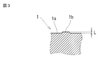
- a slight convex portion 1b may be formed on the surface of the end surface 1a.
- the height of the convex portion 1b is about 0.02 mm (see FIG. 3) and is extremely small.
- the horn 4 (or cone) of the ultrasonic welder is brought into contact with the end surface 1a of the first component 1 and ultrasonic vibration is applied, the slight convex portion 1b is pressed flat, as shown in FIG. The end of the convex portion 1b adheres to the outer periphery of the end surface 1a as the melting portion 5.
- the outer periphery of the first component 1 becomes unnatural, and the melted part 5 may be separated and adhere to each part of the part.
- the molded product as described above is a radiator cap having a valve unit therein, and when the separated melted part 5 enters the inside of the part, it is provided in the cap by the penetration of the separated melted part 5
- the valve unit may malfunction and impair the sealing performance of the radiator cap. Therefore, in the present invention, even if such a convex portion 1b is formed on the surface of the end surface 1a, it is formed so that it does not jump out to the outside during ultrasonic vibration, and the appearance is good and poor welding hardly occurs. The issue is to provide goods.
- the present invention according to claim 1 is a method of joining the first part (1) and the second part (2) each made of a resin molded product to each other by an ultrasonic welding machine.
- the end surface (1a) of the first component (1) is formed in a substantially annular plane, and there are slight protrusions (1b) on the plane, and a step is provided on at least one of the outer periphery or the inner periphery.
- the part (3) Forming the part (3); The first part (1) and the second part (2) are brought into contact with each other, the horn (4) of the welding machine is brought into contact with the end surface (1a) of the first part (1), and the first part (1 ) With ultrasonic vibration and pressing the slight convex part (1b) while forming it flush with the plane and welding the end of the convex part (1b) to the step part (3) Then, the resin molding in which the end of the convex portion (1b) does not protrude from at least one of the outer periphery or inner periphery of the end surface (1a) of the first component (1) to at least one of the outer side or the inner side in the radial direction.
- This is a method for welding products.
- the step (3) is formed in a ring shape in advance on the outer peripheral edge and the inner peripheral edge of the end face (1a).
- the end of the convex portion 1b of the end surface 1a of the first part with which the horn 4 abuts is welded, the end is accommodated in the step portion 3, and the end of the convex portion 1b Is prevented from being pushed out to the outer periphery of the component, resulting in a resin-molded product with good appearance. That is, in the welding process, when the convex portion 1b of the end surface 1a of the first component 1 is formed flush with the end surface 1a, the end of the convex portion 1b is welded to the step portion 3 provided on the periphery. Does not jump out.
- the end of the convex portion 1b when the end of the convex portion 1b is welded to the step portion 3 in this way, the end of the convex portion 1b can be prevented from separating and entering the inside of the component, so that a poorly welded resin does not occur.
- the step portion 3 is formed in an annular shape in advance on the outer peripheral edge and the inner peripheral edge of the end surface 1b, the end of the convex portion 1b is provided on the peripheral edge. It is possible to reliably weld to the stepped portion 3.
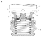
- FIG. 1 is an explanatory view showing a method for welding a resin molded product according to the present invention, and is a longitudinal sectional view of an essential part before the welding.
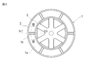
- 2 is a cross-sectional view taken along the line II-II in FIG. 3 is an enlarged cross-sectional view taken along arrow III-III in FIG.
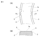
- FIG. 4 is an enlarged vertical cross-sectional view of a main part at the time of welding in the same welding method.
- FIG. 5 is a plan view taken along line V-VI in FIG. 4A and a cross-sectional view taken along line BB in FIG.
- FIG. 6 is a plan view of an end face 1 a of the conventional first component 1.
- FIG. 7 is an explanatory view of injection molding of the first component 1.
- FIG. 8 is an explanatory view of the melting portion 5 that can be made into a contact portion when the first component 1 and the horn 4 are contacted with each other in FIG. 7.
- FIG. 1 is an explanatory view for joining a valve body of a radiator as a first part 1 and a cap body as a second part 2 via an ultrasonic welding machine (not shown).
- the first component 1 and the second component 2 are fitted.
- a valve unit is interposed between them in advance.
- a negative pressure valve and a positive pressure valve are opposed to each other via an annular valve seat, and these valves are biased by a negative pressure spring and a positive pressure spring.
- the first component 1 and the second component 2 are not fixed.
- a plurality of convex portions 1b are formed in the radial direction.
- the convex portion 1b has an extremely small height of about 0.02 mm as an example.
- step portions 3 which are slight steps are formed on the outer periphery and inner periphery of the end surface 1a of the first component 1 as shown in FIGS.
- a horn 4 of an ultrasonic welding machine (not shown) is brought into contact with the end surface 1 a of the first component 1 to apply ultrasonic vibration between the first component 1 and the second component 2.
- the slight protrusion 1b described above is pushed into the plane of the end face 1a by the vibration and is formed flat.
- the melted portion 5 that can be generated from both ends of the convex portion 1b is welded to the step portion 3, and the melted portion 5 is held there. Therefore, the melted part 5 that has flowed out to the inner peripheral side and the outer peripheral side of the first component 1 during ultrasonic vibration does not jump out of the first part 1. As a result, good-quality welding is performed. Furthermore, since it can prevent that the fusion
- the lower end portion of the first component 1 is formed in an annular convex portion, and the upper end portion of the second component 2 is formed in an annular groove portion, and both are fitted as shown in FIG. And the fitting part of both welds by ultrasonic vibration.
- the 1st component 1 and the 2nd component 2 are integrated.
- the position of the end surface 1a of the first component 1 is provided with a height shifted from the position of the end surface of the spring seat on which the negative spring is placed and the end surface of the bridging portion 8 ( In this figure, the position of the end face 1a protrudes annularly above the end face of the spring seat).
- FIG. 1 the position of the end surface 1a of the first component 1 is provided with a height shifted from the position of the end surface of the spring seat on which the negative spring is placed and the end surface of the bridging portion 8 ( In this figure, the position of the end face 1a protrudes annularly above the end face of the spring seat).
- the end face 1a, the spring seat, and the bridging portion 8 are formed substantially flush.
- the surface with which the horn 4 abuts is only the end surface 1a. Therefore, the stepped portion 3 only needs to be processed on the end surface 1a, the resin radiator cap can be easily manufactured, and the convex portion 1b. It is possible to reliably weld the melted portion 5 that can be generated from the end portion to the stepped portion 3.
Landscapes
- Engineering & Computer Science (AREA)
- Mechanical Engineering (AREA)
- Lining Or Joining Of Plastics Or The Like (AREA)
Priority Applications (1)
| Application Number | Priority Date | Filing Date | Title |
|---|---|---|---|
| CN201580016059.2A CN106132667B (zh) | 2014-03-27 | 2015-02-26 | 树脂成形品的熔接方法 |
Applications Claiming Priority (2)
| Application Number | Priority Date | Filing Date | Title |
|---|---|---|---|
| JP2014-065038 | 2014-03-27 | ||
| JP2014065038A JP6339395B2 (ja) | 2014-03-27 | 2014-03-27 | 樹脂成形品の溶着方法 |
Publications (1)
| Publication Number | Publication Date |
|---|---|
| WO2015146530A1 true WO2015146530A1 (ja) | 2015-10-01 |
Family
ID=54195059
Family Applications (1)
| Application Number | Title | Priority Date | Filing Date |
|---|---|---|---|
| PCT/JP2015/056573 Ceased WO2015146530A1 (ja) | 2014-03-27 | 2015-02-26 | 樹脂成形品の溶着方法 |
Country Status (4)
| Country | Link |
|---|---|
| JP (1) | JP6339395B2 (enExample) |
| CN (1) | CN106132667B (enExample) |
| TW (1) | TWI613062B (enExample) |
| WO (1) | WO2015146530A1 (enExample) |
Cited By (1)
| Publication number | Priority date | Publication date | Assignee | Title |
|---|---|---|---|---|
| JP2016022995A (ja) * | 2014-07-25 | 2016-02-08 | 株式会社カネカ | 気密性耐圧容器 |
Citations (5)
| Publication number | Priority date | Publication date | Assignee | Title |
|---|---|---|---|---|
| JPH03494A (ja) * | 1989-05-30 | 1991-01-07 | Koito Mfg Co Ltd | 超音波溶着方法および超音波ホーンならびに超音波溶着体 |
| JPH1110742A (ja) * | 1997-06-24 | 1999-01-19 | Fuji Photo Film Co Ltd | 磁気テープカートリッジ用リールの溶着方法及び溶着装置 |
| JP2003137205A (ja) * | 2001-11-06 | 2003-05-14 | Ricoh Co Ltd | 超音波溶着工法及びトナーケース |
| JP2008238437A (ja) * | 2007-03-26 | 2008-10-09 | Toray Ind Inc | 容器の製造方法 |
| JP2010208197A (ja) * | 2009-03-11 | 2010-09-24 | Olympus Corp | パイプの接合方法及びパイプの接合構造 |
Family Cites Families (6)
| Publication number | Priority date | Publication date | Assignee | Title |
|---|---|---|---|---|
| JP4132353B2 (ja) * | 1999-02-22 | 2008-08-13 | 株式会社小糸製作所 | 車輌灯具用レンズ |
| JP2005007623A (ja) * | 2003-06-17 | 2005-01-13 | Aisan Ind Co Ltd | 3部材の溶接構造 |
| JP2005169721A (ja) * | 2003-12-09 | 2005-06-30 | Kojima Press Co Ltd | 振動溶着装置及び振動溶着方法 |
| CN2894917Y (zh) * | 2006-01-13 | 2007-05-02 | 陈岳文 | 一种平移焊接式超声波焊接模板 |
| GB2446385A (en) * | 2007-02-12 | 2008-08-13 | Inbev Sa | Laser welding valve assembly to beer keg |
| DE102011005997A1 (de) * | 2011-03-23 | 2012-09-27 | Robert Bosch Gmbh | Verfahren zum Anbringen einer Öffnungs- und Schliessvorrichtung auf einen Schlauchbeutel mittels Ultraschallschweissung |
-
2014
- 2014-03-27 JP JP2014065038A patent/JP6339395B2/ja active Active
-
2015
- 2015-02-26 CN CN201580016059.2A patent/CN106132667B/zh active Active
- 2015-02-26 WO PCT/JP2015/056573 patent/WO2015146530A1/ja not_active Ceased
- 2015-03-23 TW TW104109171A patent/TWI613062B/zh active
Patent Citations (5)
| Publication number | Priority date | Publication date | Assignee | Title |
|---|---|---|---|---|
| JPH03494A (ja) * | 1989-05-30 | 1991-01-07 | Koito Mfg Co Ltd | 超音波溶着方法および超音波ホーンならびに超音波溶着体 |
| JPH1110742A (ja) * | 1997-06-24 | 1999-01-19 | Fuji Photo Film Co Ltd | 磁気テープカートリッジ用リールの溶着方法及び溶着装置 |
| JP2003137205A (ja) * | 2001-11-06 | 2003-05-14 | Ricoh Co Ltd | 超音波溶着工法及びトナーケース |
| JP2008238437A (ja) * | 2007-03-26 | 2008-10-09 | Toray Ind Inc | 容器の製造方法 |
| JP2010208197A (ja) * | 2009-03-11 | 2010-09-24 | Olympus Corp | パイプの接合方法及びパイプの接合構造 |
Cited By (1)
| Publication number | Priority date | Publication date | Assignee | Title |
|---|---|---|---|---|
| JP2016022995A (ja) * | 2014-07-25 | 2016-02-08 | 株式会社カネカ | 気密性耐圧容器 |
Also Published As
| Publication number | Publication date |
|---|---|
| JP6339395B2 (ja) | 2018-06-06 |
| TWI613062B (zh) | 2018-02-01 |
| TW201600315A (zh) | 2016-01-01 |
| CN106132667A (zh) | 2016-11-16 |
| CN106132667B (zh) | 2018-07-27 |
| JP2015186872A (ja) | 2015-10-29 |
Similar Documents
| Publication | Publication Date | Title |
|---|---|---|
| JP4568720B2 (ja) | バイザー付ヘルメット | |
| JP6339395B2 (ja) | 樹脂成形品の溶着方法 | |
| JP2009274429A5 (enExample) | ||
| US10717489B2 (en) | Resin-made tank | |
| KR101418914B1 (ko) | 도어트림내 부품들의 융착구조 | |
| JP5426143B2 (ja) | 射出成形体の製造方法 | |
| JP2012192604A (ja) | 射出成形方法 | |
| JP4790832B2 (ja) | 樹脂溶着体の製造方法 | |
| JP2008155587A (ja) | 中空樹脂成形品の製造方法 | |
| CN105818365B (zh) | 树脂部件以及树脂部件的接合方法 | |
| US10981616B2 (en) | Resin-made fuel tank | |
| WO2019172025A1 (ja) | 接合構造及び接合方法 | |
| JP7546208B2 (ja) | 接合構造 | |
| JP5656896B2 (ja) | 合成樹脂部品の接合方法 | |
| JP2015186872A5 (enExample) | ||
| KR101774088B1 (ko) | 플라스틱탱크, 플라스틱탱크 열융착 시스템 및 방법 | |
| US20180266650A1 (en) | Interlocking joints for injection molded part | |
| JPH08238627A (ja) | 樹脂−ゴム一体成形用金型及びこれを用いた成形方法 | |
| JP6704885B2 (ja) | 樹脂製燃料タンク | |
| JP2017101693A (ja) | ダイヤフラムバルブおよびその製造方法 | |
| KR20170010873A (ko) | 플라스틱탱크 | |
| KR101930405B1 (ko) | 도어트림 융착구조 | |
| US1196473A (en) | Electrical welding. | |
| JP2007182943A (ja) | 端部にフランジ部を有する樹脂製パイプ | |
| JP6583051B2 (ja) | 樹脂燃料タンクの製造方法 |
Legal Events
| Date | Code | Title | Description |
|---|---|---|---|
| 121 | Ep: the epo has been informed by wipo that ep was designated in this application |
Ref document number: 15768806 Country of ref document: EP Kind code of ref document: A1 |
|
| NENP | Non-entry into the national phase |
Ref country code: DE |
|
| 122 | Ep: pct application non-entry in european phase |
Ref document number: 15768806 Country of ref document: EP Kind code of ref document: A1 |