WO2015146530A1 - Welding method for resin molding - Google Patents
Welding method for resin molding Download PDFInfo
- Publication number
- WO2015146530A1 WO2015146530A1 PCT/JP2015/056573 JP2015056573W WO2015146530A1 WO 2015146530 A1 WO2015146530 A1 WO 2015146530A1 JP 2015056573 W JP2015056573 W JP 2015056573W WO 2015146530 A1 WO2015146530 A1 WO 2015146530A1
- Authority
- WO
- WIPO (PCT)
- Prior art keywords
- component
- welding
- end surface
- resin molded
- convex portion
- Prior art date
Links
Images


Classifications
-
- B—PERFORMING OPERATIONS; TRANSPORTING
- B29—WORKING OF PLASTICS; WORKING OF SUBSTANCES IN A PLASTIC STATE IN GENERAL
- B29C—SHAPING OR JOINING OF PLASTICS; SHAPING OF MATERIAL IN A PLASTIC STATE, NOT OTHERWISE PROVIDED FOR; AFTER-TREATMENT OF THE SHAPED PRODUCTS, e.g. REPAIRING
- B29C65/00—Joining or sealing of preformed parts, e.g. welding of plastics materials; Apparatus therefor
- B29C65/02—Joining or sealing of preformed parts, e.g. welding of plastics materials; Apparatus therefor by heating, with or without pressure
- B29C65/08—Joining or sealing of preformed parts, e.g. welding of plastics materials; Apparatus therefor by heating, with or without pressure using ultrasonic vibrations
-
- B—PERFORMING OPERATIONS; TRANSPORTING
- B29—WORKING OF PLASTICS; WORKING OF SUBSTANCES IN A PLASTIC STATE IN GENERAL
- B29C—SHAPING OR JOINING OF PLASTICS; SHAPING OF MATERIAL IN A PLASTIC STATE, NOT OTHERWISE PROVIDED FOR; AFTER-TREATMENT OF THE SHAPED PRODUCTS, e.g. REPAIRING
- B29C66/00—General aspects of processes or apparatus for joining preformed parts
- B29C66/01—General aspects dealing with the joint area or with the area to be joined
- B29C66/05—Particular design of joint configurations
- B29C66/10—Particular design of joint configurations particular design of the joint cross-sections
- B29C66/12—Joint cross-sections combining only two joint-segments; Tongue and groove joints; Tenon and mortise joints; Stepped joint cross-sections
- B29C66/124—Tongue and groove joints
- B29C66/1244—Tongue and groove joints characterised by the male part, i.e. the part comprising the tongue
- B29C66/12449—Tongue and groove joints characterised by the male part, i.e. the part comprising the tongue being asymmetric
-
- B—PERFORMING OPERATIONS; TRANSPORTING
- B29—WORKING OF PLASTICS; WORKING OF SUBSTANCES IN A PLASTIC STATE IN GENERAL
- B29C—SHAPING OR JOINING OF PLASTICS; SHAPING OF MATERIAL IN A PLASTIC STATE, NOT OTHERWISE PROVIDED FOR; AFTER-TREATMENT OF THE SHAPED PRODUCTS, e.g. REPAIRING
- B29C66/00—General aspects of processes or apparatus for joining preformed parts
- B29C66/01—General aspects dealing with the joint area or with the area to be joined
- B29C66/05—Particular design of joint configurations
- B29C66/10—Particular design of joint configurations particular design of the joint cross-sections
- B29C66/12—Joint cross-sections combining only two joint-segments; Tongue and groove joints; Tenon and mortise joints; Stepped joint cross-sections
- B29C66/124—Tongue and groove joints
- B29C66/1246—Tongue and groove joints characterised by the female part, i.e. the part comprising the groove
- B29C66/12469—Tongue and groove joints characterised by the female part, i.e. the part comprising the groove being asymmetric
-
- B—PERFORMING OPERATIONS; TRANSPORTING
- B29—WORKING OF PLASTICS; WORKING OF SUBSTANCES IN A PLASTIC STATE IN GENERAL
- B29C—SHAPING OR JOINING OF PLASTICS; SHAPING OF MATERIAL IN A PLASTIC STATE, NOT OTHERWISE PROVIDED FOR; AFTER-TREATMENT OF THE SHAPED PRODUCTS, e.g. REPAIRING
- B29C66/00—General aspects of processes or apparatus for joining preformed parts
- B29C66/01—General aspects dealing with the joint area or with the area to be joined
- B29C66/32—Measures for keeping the burr form under control; Avoiding burr formation; Shaping the burr
- B29C66/322—Providing cavities in the joined article to collect the burr
-
- B—PERFORMING OPERATIONS; TRANSPORTING
- B29—WORKING OF PLASTICS; WORKING OF SUBSTANCES IN A PLASTIC STATE IN GENERAL
- B29C—SHAPING OR JOINING OF PLASTICS; SHAPING OF MATERIAL IN A PLASTIC STATE, NOT OTHERWISE PROVIDED FOR; AFTER-TREATMENT OF THE SHAPED PRODUCTS, e.g. REPAIRING
- B29C66/00—General aspects of processes or apparatus for joining preformed parts
- B29C66/01—General aspects dealing with the joint area or with the area to be joined
- B29C66/32—Measures for keeping the burr form under control; Avoiding burr formation; Shaping the burr
- B29C66/324—Avoiding burr formation
-
- B—PERFORMING OPERATIONS; TRANSPORTING
- B29—WORKING OF PLASTICS; WORKING OF SUBSTANCES IN A PLASTIC STATE IN GENERAL
- B29C—SHAPING OR JOINING OF PLASTICS; SHAPING OF MATERIAL IN A PLASTIC STATE, NOT OTHERWISE PROVIDED FOR; AFTER-TREATMENT OF THE SHAPED PRODUCTS, e.g. REPAIRING
- B29C66/00—General aspects of processes or apparatus for joining preformed parts
- B29C66/50—General aspects of joining tubular articles; General aspects of joining long products, i.e. bars or profiled elements; General aspects of joining single elements to tubular articles, hollow articles or bars; General aspects of joining several hollow-preforms to form hollow or tubular articles
- B29C66/51—Joining tubular articles, profiled elements or bars; Joining single elements to tubular articles, hollow articles or bars; Joining several hollow-preforms to form hollow or tubular articles
- B29C66/54—Joining several hollow-preforms, e.g. half-shells, to form hollow articles, e.g. for making balls, containers; Joining several hollow-preforms, e.g. half-cylinders, to form tubular articles
-
- B—PERFORMING OPERATIONS; TRANSPORTING
- B29—WORKING OF PLASTICS; WORKING OF SUBSTANCES IN A PLASTIC STATE IN GENERAL
- B29C—SHAPING OR JOINING OF PLASTICS; SHAPING OF MATERIAL IN A PLASTIC STATE, NOT OTHERWISE PROVIDED FOR; AFTER-TREATMENT OF THE SHAPED PRODUCTS, e.g. REPAIRING
- B29C66/00—General aspects of processes or apparatus for joining preformed parts
- B29C66/80—General aspects of machine operations or constructions and parts thereof
- B29C66/83—General aspects of machine operations or constructions and parts thereof characterised by the movement of the joining or pressing tools
- B29C66/832—Reciprocating joining or pressing tools
- B29C66/8322—Joining or pressing tools reciprocating along one axis
-
- B—PERFORMING OPERATIONS; TRANSPORTING
- B29—WORKING OF PLASTICS; WORKING OF SUBSTANCES IN A PLASTIC STATE IN GENERAL
- B29L—INDEXING SCHEME ASSOCIATED WITH SUBCLASS B29C, RELATING TO PARTICULAR ARTICLES
- B29L2031/00—Other particular articles
- B29L2031/18—Heat-exchangers or parts thereof
Definitions
- the present invention relates to a joining method for joining a first part made of resin and a second part using an ultrasonic welding machine.
- the resin-made radiator cap can form a valve main body and a cap main body by a resin molded product, respectively, can fit both, and can join the junction part by ultrasonic welding.
- FIG. 6 to 8 show a conventional method of welding a resin molded product
- FIG. 6 is a plan view of the first component 1
- FIG. 7 is a longitudinal sectional view thereof.
- molten resin 7 is injected into the inside from the center of the molding die, and as shown in FIG. It leads to the radial direction outer side via the some bridge
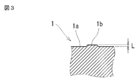
- a slight convex portion 1b may be formed on the surface of the end surface 1a.
- the height of the convex portion 1b is about 0.02 mm (see FIG. 3) and is extremely small.
- the horn 4 (or cone) of the ultrasonic welder is brought into contact with the end surface 1a of the first component 1 and ultrasonic vibration is applied, the slight convex portion 1b is pressed flat, as shown in FIG. The end of the convex portion 1b adheres to the outer periphery of the end surface 1a as the melting portion 5.
- the outer periphery of the first component 1 becomes unnatural, and the melted part 5 may be separated and adhere to each part of the part.
- the molded product as described above is a radiator cap having a valve unit therein, and when the separated melted part 5 enters the inside of the part, it is provided in the cap by the penetration of the separated melted part 5
- the valve unit may malfunction and impair the sealing performance of the radiator cap. Therefore, in the present invention, even if such a convex portion 1b is formed on the surface of the end surface 1a, it is formed so that it does not jump out to the outside during ultrasonic vibration, and the appearance is good and poor welding hardly occurs. The issue is to provide goods.
- the present invention according to claim 1 is a method of joining the first part (1) and the second part (2) each made of a resin molded product to each other by an ultrasonic welding machine.
- the end surface (1a) of the first component (1) is formed in a substantially annular plane, and there are slight protrusions (1b) on the plane, and a step is provided on at least one of the outer periphery or the inner periphery.
- the part (3) Forming the part (3); The first part (1) and the second part (2) are brought into contact with each other, the horn (4) of the welding machine is brought into contact with the end surface (1a) of the first part (1), and the first part (1 ) With ultrasonic vibration and pressing the slight convex part (1b) while forming it flush with the plane and welding the end of the convex part (1b) to the step part (3) Then, the resin molding in which the end of the convex portion (1b) does not protrude from at least one of the outer periphery or inner periphery of the end surface (1a) of the first component (1) to at least one of the outer side or the inner side in the radial direction.
- This is a method for welding products.
- the step (3) is formed in a ring shape in advance on the outer peripheral edge and the inner peripheral edge of the end face (1a).
- the end of the convex portion 1b of the end surface 1a of the first part with which the horn 4 abuts is welded, the end is accommodated in the step portion 3, and the end of the convex portion 1b Is prevented from being pushed out to the outer periphery of the component, resulting in a resin-molded product with good appearance. That is, in the welding process, when the convex portion 1b of the end surface 1a of the first component 1 is formed flush with the end surface 1a, the end of the convex portion 1b is welded to the step portion 3 provided on the periphery. Does not jump out.
- the end of the convex portion 1b when the end of the convex portion 1b is welded to the step portion 3 in this way, the end of the convex portion 1b can be prevented from separating and entering the inside of the component, so that a poorly welded resin does not occur.
- the step portion 3 is formed in an annular shape in advance on the outer peripheral edge and the inner peripheral edge of the end surface 1b, the end of the convex portion 1b is provided on the peripheral edge. It is possible to reliably weld to the stepped portion 3.
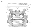
- FIG. 1 is an explanatory view showing a method for welding a resin molded product according to the present invention, and is a longitudinal sectional view of an essential part before the welding.
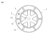
- 2 is a cross-sectional view taken along the line II-II in FIG. 3 is an enlarged cross-sectional view taken along arrow III-III in FIG.
- FIG. 4 is an enlarged vertical cross-sectional view of a main part at the time of welding in the same welding method.
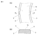
- FIG. 5 is a plan view taken along line V-VI in FIG. 4A and a cross-sectional view taken along line BB in FIG.
- FIG. 6 is a plan view of an end face 1 a of the conventional first component 1.
- FIG. 7 is an explanatory view of injection molding of the first component 1.
- FIG. 8 is an explanatory view of the melting portion 5 that can be made into a contact portion when the first component 1 and the horn 4 are contacted with each other in FIG. 7.
- FIG. 1 is an explanatory view for joining a valve body of a radiator as a first part 1 and a cap body as a second part 2 via an ultrasonic welding machine (not shown).
- the first component 1 and the second component 2 are fitted.
- a valve unit is interposed between them in advance.
- a negative pressure valve and a positive pressure valve are opposed to each other via an annular valve seat, and these valves are biased by a negative pressure spring and a positive pressure spring.
- the first component 1 and the second component 2 are not fixed.
- a plurality of convex portions 1b are formed in the radial direction.
- the convex portion 1b has an extremely small height of about 0.02 mm as an example.
- step portions 3 which are slight steps are formed on the outer periphery and inner periphery of the end surface 1a of the first component 1 as shown in FIGS.
- a horn 4 of an ultrasonic welding machine (not shown) is brought into contact with the end surface 1 a of the first component 1 to apply ultrasonic vibration between the first component 1 and the second component 2.
- the slight protrusion 1b described above is pushed into the plane of the end face 1a by the vibration and is formed flat.
- the melted portion 5 that can be generated from both ends of the convex portion 1b is welded to the step portion 3, and the melted portion 5 is held there. Therefore, the melted part 5 that has flowed out to the inner peripheral side and the outer peripheral side of the first component 1 during ultrasonic vibration does not jump out of the first part 1. As a result, good-quality welding is performed. Furthermore, since it can prevent that the fusion
- the lower end portion of the first component 1 is formed in an annular convex portion, and the upper end portion of the second component 2 is formed in an annular groove portion, and both are fitted as shown in FIG. And the fitting part of both welds by ultrasonic vibration.
- the 1st component 1 and the 2nd component 2 are integrated.
- the position of the end surface 1a of the first component 1 is provided with a height shifted from the position of the end surface of the spring seat on which the negative spring is placed and the end surface of the bridging portion 8 ( In this figure, the position of the end face 1a protrudes annularly above the end face of the spring seat).
- FIG. 1 the position of the end surface 1a of the first component 1 is provided with a height shifted from the position of the end surface of the spring seat on which the negative spring is placed and the end surface of the bridging portion 8 ( In this figure, the position of the end face 1a protrudes annularly above the end face of the spring seat).
- the end face 1a, the spring seat, and the bridging portion 8 are formed substantially flush.
- the surface with which the horn 4 abuts is only the end surface 1a. Therefore, the stepped portion 3 only needs to be processed on the end surface 1a, the resin radiator cap can be easily manufactured, and the convex portion 1b. It is possible to reliably weld the melted portion 5 that can be generated from the end portion to the stepped portion 3.
Abstract
When a horn (4) of an ultrasonic welding machine is brought into contact with an end face of a first component (1), the outflow of molten matters from the inner and outer peripheries can be prevented by preliminarily forming a staircase part (3) in the end face (1a) of the first component (1) and housing an end part of a convex part (1b) in the staircase part (3).
Description
本発明は、樹脂製の第1部品と第2部品とを超音波溶着機によって接合する接合方法に関する。
The present invention relates to a joining method for joining a first part made of resin and a second part using an ultrasonic welding machine.
一例として、樹脂製ラジエータキャップは、弁本体とキャップ本体とを夫々樹脂成形品で形成し、両者を嵌着し、その接合部を超音波溶着により接合することができる。
第1部品と第2部品とが夫々複雑な形状をしている場合、各部品ごとに成形し、両部品を接合することにより、より複雑な部品を完成することができる。
図6~図8は従来の樹脂成形品の溶着方法であり、図6はその第1部品1の平面図、図7は同縦断面図である。
上記のような環状の第1部品1を射出成形により形成するには、図7に示す如く、成形用金型の中心から溶融した樹脂7を内部に注入し、それを図6に示す如く、複数の架橋部8を介して半径方向外側に導くことになる。 As an example, the resin-made radiator cap can form a valve main body and a cap main body by a resin molded product, respectively, can fit both, and can join the junction part by ultrasonic welding.
When the first part and the second part have complicated shapes, a more complicated part can be completed by molding each part and joining both parts.
6 to 8 show a conventional method of welding a resin molded product, FIG. 6 is a plan view of thefirst component 1, and FIG. 7 is a longitudinal sectional view thereof.
In order to form the annularfirst component 1 as described above by injection molding, as shown in FIG. 7, molten resin 7 is injected into the inside from the center of the molding die, and as shown in FIG. It leads to the radial direction outer side via the some bridge | crosslinking part 8. FIG.
第1部品と第2部品とが夫々複雑な形状をしている場合、各部品ごとに成形し、両部品を接合することにより、より複雑な部品を完成することができる。
図6~図8は従来の樹脂成形品の溶着方法であり、図6はその第1部品1の平面図、図7は同縦断面図である。
上記のような環状の第1部品1を射出成形により形成するには、図7に示す如く、成形用金型の中心から溶融した樹脂7を内部に注入し、それを図6に示す如く、複数の架橋部8を介して半径方向外側に導くことになる。 As an example, the resin-made radiator cap can form a valve main body and a cap main body by a resin molded product, respectively, can fit both, and can join the junction part by ultrasonic welding.
When the first part and the second part have complicated shapes, a more complicated part can be completed by molding each part and joining both parts.
6 to 8 show a conventional method of welding a resin molded product, FIG. 6 is a plan view of the
In order to form the annular
ところが、複数の架橋部8を介して溶融する樹脂7を環状部に供給するとき、その端面1aの表面に、僅かな凸部1bが形成されることがある。その凸部1bの高さは、一例として0.02mm(図3参照)程度で極めて僅かである。
ところが、その第1部品1の端面1aに超音波溶接機のホーン4(またはコーンともいう)を当接し、超音波振動を与えると、僅かな凸部1bが平坦に押圧され、図8の如く、凸部1bの端部が端面1aの外周に溶融部5として付着する。そのため、第1部品1の外周が不体裁になると共に、その溶融部5が分離して部品の各部に付着するおそれがある。
上記のような成形品が弁ユニットを内部に有するラジエータキャップであった場合であり、分離した溶融部5が部品内部に浸入したときは、その分離した溶融部5の侵入によりキャップ内に設けられる弁ユニットが動作不良を起こし、ラジエータキャップのシール性を損なうおそれがある。
そこで、本発明はこのような凸部1bが端面1aの表面に形成されても、超音波振動の際にそれが外部に飛び出さないようにして、体裁が良く、且つ溶着不良が生じ難い成形品を提供することを課題とする。 However, when theresin 7 that melts through the plurality of bridging portions 8 is supplied to the annular portion, a slight convex portion 1b may be formed on the surface of the end surface 1a. As an example, the height of the convex portion 1b is about 0.02 mm (see FIG. 3) and is extremely small.
However, when the horn 4 (or cone) of the ultrasonic welder is brought into contact with theend surface 1a of the first component 1 and ultrasonic vibration is applied, the slight convex portion 1b is pressed flat, as shown in FIG. The end of the convex portion 1b adheres to the outer periphery of the end surface 1a as the melting portion 5. For this reason, the outer periphery of the first component 1 becomes unnatural, and the melted part 5 may be separated and adhere to each part of the part.
This is a case where the molded product as described above is a radiator cap having a valve unit therein, and when the separated meltedpart 5 enters the inside of the part, it is provided in the cap by the penetration of the separated melted part 5 The valve unit may malfunction and impair the sealing performance of the radiator cap.
Therefore, in the present invention, even if such aconvex portion 1b is formed on the surface of the end surface 1a, it is formed so that it does not jump out to the outside during ultrasonic vibration, and the appearance is good and poor welding hardly occurs. The issue is to provide goods.
ところが、その第1部品1の端面1aに超音波溶接機のホーン4(またはコーンともいう)を当接し、超音波振動を与えると、僅かな凸部1bが平坦に押圧され、図8の如く、凸部1bの端部が端面1aの外周に溶融部5として付着する。そのため、第1部品1の外周が不体裁になると共に、その溶融部5が分離して部品の各部に付着するおそれがある。
上記のような成形品が弁ユニットを内部に有するラジエータキャップであった場合であり、分離した溶融部5が部品内部に浸入したときは、その分離した溶融部5の侵入によりキャップ内に設けられる弁ユニットが動作不良を起こし、ラジエータキャップのシール性を損なうおそれがある。
そこで、本発明はこのような凸部1bが端面1aの表面に形成されても、超音波振動の際にそれが外部に飛び出さないようにして、体裁が良く、且つ溶着不良が生じ難い成形品を提供することを課題とする。 However, when the
However, when the horn 4 (or cone) of the ultrasonic welder is brought into contact with the
This is a case where the molded product as described above is a radiator cap having a valve unit therein, and when the separated melted
Therefore, in the present invention, even if such a
請求項1に記載の本発明は、それぞれ樹脂成形品よりなる第1部品(1)と第2部品(2)とを超音波溶着機により、互いに接合する方法において、
第1部品(1)の端面(1a)が、略環状の平面に形成され、その平面に僅かの凸部(1b)が存在するものであって、その外周又は内周の少なくとも一方に、段部(3)を形成しておく工程と、
その第1部品(1)と、第2部品(2)とを接触させ、溶着機のホーン(4)を第1部品(1)の前記端面(1a)に当接し、その第1部品(1)に超音波振動を与え、前記僅かの凸部(1b)を押圧しつつ、それを平面に面一に形成すると共に、その凸部(1b)の端部を前記段部(3)に溶着して、凸部(1b)の端部が第1部品(1)の端面(1a)の外周又は内周の少なくとも一方から、半径方向の外側又は内側の少なくとも一方に突出しないようにした樹脂成形品の溶着方法である。
請求項2に記載の本発明は、請求項1に記載の樹脂成形品の溶着方法において、
前記段部(3)を端面(1a)の外周縁および内周縁に、予め環状に形成しておいたことを特徴とする樹脂成形品の溶着方法である。 The present invention according toclaim 1 is a method of joining the first part (1) and the second part (2) each made of a resin molded product to each other by an ultrasonic welding machine.
The end surface (1a) of the first component (1) is formed in a substantially annular plane, and there are slight protrusions (1b) on the plane, and a step is provided on at least one of the outer periphery or the inner periphery. Forming the part (3);
The first part (1) and the second part (2) are brought into contact with each other, the horn (4) of the welding machine is brought into contact with the end surface (1a) of the first part (1), and the first part (1 ) With ultrasonic vibration and pressing the slight convex part (1b) while forming it flush with the plane and welding the end of the convex part (1b) to the step part (3) Then, the resin molding in which the end of the convex portion (1b) does not protrude from at least one of the outer periphery or inner periphery of the end surface (1a) of the first component (1) to at least one of the outer side or the inner side in the radial direction. This is a method for welding products.
According to a second aspect of the present invention, in the method for welding a resin molded product according to the first aspect,
The step (3) is formed in a ring shape in advance on the outer peripheral edge and the inner peripheral edge of the end face (1a).
第1部品(1)の端面(1a)が、略環状の平面に形成され、その平面に僅かの凸部(1b)が存在するものであって、その外周又は内周の少なくとも一方に、段部(3)を形成しておく工程と、
その第1部品(1)と、第2部品(2)とを接触させ、溶着機のホーン(4)を第1部品(1)の前記端面(1a)に当接し、その第1部品(1)に超音波振動を与え、前記僅かの凸部(1b)を押圧しつつ、それを平面に面一に形成すると共に、その凸部(1b)の端部を前記段部(3)に溶着して、凸部(1b)の端部が第1部品(1)の端面(1a)の外周又は内周の少なくとも一方から、半径方向の外側又は内側の少なくとも一方に突出しないようにした樹脂成形品の溶着方法である。
請求項2に記載の本発明は、請求項1に記載の樹脂成形品の溶着方法において、
前記段部(3)を端面(1a)の外周縁および内周縁に、予め環状に形成しておいたことを特徴とする樹脂成形品の溶着方法である。 The present invention according to
The end surface (1a) of the first component (1) is formed in a substantially annular plane, and there are slight protrusions (1b) on the plane, and a step is provided on at least one of the outer periphery or the inner periphery. Forming the part (3);
The first part (1) and the second part (2) are brought into contact with each other, the horn (4) of the welding machine is brought into contact with the end surface (1a) of the first part (1), and the first part (1 ) With ultrasonic vibration and pressing the slight convex part (1b) while forming it flush with the plane and welding the end of the convex part (1b) to the step part (3) Then, the resin molding in which the end of the convex portion (1b) does not protrude from at least one of the outer periphery or inner periphery of the end surface (1a) of the first component (1) to at least one of the outer side or the inner side in the radial direction. This is a method for welding products.
According to a second aspect of the present invention, in the method for welding a resin molded product according to the first aspect,
The step (3) is formed in a ring shape in advance on the outer peripheral edge and the inner peripheral edge of the end face (1a).
本発明の樹脂成形品の溶着方法によれば、ホーン4が当接する第1部品の端面1aの凸部1bが溶着されるとき、その端が段部3に収納され、その凸部1bの端が部品の外周に押し出されることを防止し、体裁のよい樹脂成形品となる。即ち、溶着工程で、第1部品1の端面1aの凸部1bが、端面1aと面一に形成されたとき、その凸部1bの端が、周縁に設けた段部3に溶着され、それが外部に飛び出ることがない。また、このように凸部1bの端を段部3に溶着した場合、その凸部1bの端が分離して部品の内部に浸入することを防止することができるため、溶着不良が生じ難い樹脂成形品を提供できる。
一例として、ラジエータキャップの場合は、凸部1bの端部から生じうる溶融部5が内部に侵入することを防止できるため、そのシール性が損なわれることを効果的に防止しうる。
請求項2に記載の樹脂成形品の溶着方法によれば、段部3を端面1bの外周縁および内周縁に、予め環状に形成しておいたので、凸部1bの端を、周縁に設けた段部3に確実に溶着することができる。 According to the welding method of the resin molded product of the present invention, when theconvex portion 1b of the end surface 1a of the first part with which the horn 4 abuts is welded, the end is accommodated in the step portion 3, and the end of the convex portion 1b Is prevented from being pushed out to the outer periphery of the component, resulting in a resin-molded product with good appearance. That is, in the welding process, when the convex portion 1b of the end surface 1a of the first component 1 is formed flush with the end surface 1a, the end of the convex portion 1b is welded to the step portion 3 provided on the periphery. Does not jump out. In addition, when the end of the convex portion 1b is welded to the step portion 3 in this way, the end of the convex portion 1b can be prevented from separating and entering the inside of the component, so that a poorly welded resin does not occur. Can provide molded products.
As an example, in the case of a radiator cap, it is possible to prevent the meltedportion 5 that can be generated from the end portion of the convex portion 1b from entering the inside, and thus it is possible to effectively prevent the sealing performance from being impaired.
According to the method for welding a resin molded product according toclaim 2, since the step portion 3 is formed in an annular shape in advance on the outer peripheral edge and the inner peripheral edge of the end surface 1b, the end of the convex portion 1b is provided on the peripheral edge. It is possible to reliably weld to the stepped portion 3.
一例として、ラジエータキャップの場合は、凸部1bの端部から生じうる溶融部5が内部に侵入することを防止できるため、そのシール性が損なわれることを効果的に防止しうる。
請求項2に記載の樹脂成形品の溶着方法によれば、段部3を端面1bの外周縁および内周縁に、予め環状に形成しておいたので、凸部1bの端を、周縁に設けた段部3に確実に溶着することができる。 According to the welding method of the resin molded product of the present invention, when the
As an example, in the case of a radiator cap, it is possible to prevent the melted
According to the method for welding a resin molded product according to
図1は本発明の樹脂成形品の溶着方法を示す説明図であって、その溶着前の要部縦断面図。
図2は図1のII−II矢視断面図。
図3は図2のIII−III矢視断面拡大図。
図4は同溶着方法の溶着時の要部縦断面拡大図。
図5は図4のV−VI矢視平面図(A)、同(A)のB−B矢視断面図。
図6は従来の第1部品1の端面1aの平面図。
図7は同第1部品1の射出成形説明図。
図8は図7において、第1部品1とホーン4とを当接したとき、当接部にできる溶融部5の説明図。 FIG. 1 is an explanatory view showing a method for welding a resin molded product according to the present invention, and is a longitudinal sectional view of an essential part before the welding.
2 is a cross-sectional view taken along the line II-II in FIG.
3 is an enlarged cross-sectional view taken along arrow III-III in FIG.
FIG. 4 is an enlarged vertical cross-sectional view of a main part at the time of welding in the same welding method.
FIG. 5 is a plan view taken along line V-VI in FIG. 4A and a cross-sectional view taken along line BB in FIG.
FIG. 6 is a plan view of anend face 1 a of the conventional first component 1.
FIG. 7 is an explanatory view of injection molding of thefirst component 1.
FIG. 8 is an explanatory view of themelting portion 5 that can be made into a contact portion when the first component 1 and the horn 4 are contacted with each other in FIG. 7.
図2は図1のII−II矢視断面図。
図3は図2のIII−III矢視断面拡大図。
図4は同溶着方法の溶着時の要部縦断面拡大図。
図5は図4のV−VI矢視平面図(A)、同(A)のB−B矢視断面図。
図6は従来の第1部品1の端面1aの平面図。
図7は同第1部品1の射出成形説明図。
図8は図7において、第1部品1とホーン4とを当接したとき、当接部にできる溶融部5の説明図。 FIG. 1 is an explanatory view showing a method for welding a resin molded product according to the present invention, and is a longitudinal sectional view of an essential part before the welding.
2 is a cross-sectional view taken along the line II-II in FIG.
3 is an enlarged cross-sectional view taken along arrow III-III in FIG.
FIG. 4 is an enlarged vertical cross-sectional view of a main part at the time of welding in the same welding method.
FIG. 5 is a plan view taken along line V-VI in FIG. 4A and a cross-sectional view taken along line BB in FIG.
FIG. 6 is a plan view of an
FIG. 7 is an explanatory view of injection molding of the
FIG. 8 is an explanatory view of the
次に、図面に基づいて本発明の実施の形態につき説明する。
本実施例は、一例として、ラジエータ等のフィラーネック部に着脱自在に装着され、一対の分割体からなるラジエータキャップについて説明する。
図1は、第1部品1としてラジエータの弁本体と、第2部品2として同キャップ本体とを、図示しない超音波溶接機を介して接合する説明図である。
先ず、第1部品1と第2部品2とを嵌着する。それらの間には、予め、弁ユニットが介装されている。この弁ユニットは、図1の如く、負圧弁と正圧弁が環状の弁座を介して対向しており、それらの弁が負圧スプリングと正圧スプリングにより付勢されている。この時点では、第1部品1と第2部品2とは固定されていない。
その第1部品1の端面1aの表面には、凸部1bが放射方向に複数形成されている。この凸部1bは、図3に示す如く、その高さが一例として0.02mm程度の極めて僅かなものである。
次に、この発明では、第1部品1の端面1aの外周及び内周には、僅かな段差である段部3が図1及び図2に示す如く形成されている。そして、図示しない超音波溶着機のホーン4を第1部品1の端面1aに当接し、第1部品1及び第2部品2間に超音波振動を与える。
前述の僅かな凸部1bはその振動によって、端面1aの平面内に押し込まれて平坦に形成される。それと共に、図4又は図5の如く、その凸部1bの両端部から生じうる溶融部5は段部3に溶着し、そこに溶融部5が保持される。そのため、超音波振動時に第1部品1の内周側及び外周側に流出した溶融部5は、そこから外部に飛び出ることがない。それにより、体裁の良い溶着が行われる。さらに、ラジエータキャップの内部に溶融部5が侵入することを防止することができるため、弁ユニットの動作に影響を及ぼすことがない。
このとき、図1において第1部品1の下端部は環状の凸部に形成され、第2部品2の上端部は環状の溝部に形成され、両者が同図の如く嵌着している。そして超音波振動によって、両者の嵌着部が溶着する。それにより、第1部品1と第2部品2とは一体化される。
さらに、図1に記載の如く、第1部品1の端面1aの位置は、負スプリングが載置されるスプリング座の端面と架橋部8の端面の位置から高さをずらして設けられている(この図では、端面1aの位置がスプリング座の端面より上方に環状に突出している)。これに対し、従来技術の図7では、端面1aとスプリング座と架橋部8が略面一に形成されている。
このような構造とした場合、ホーン4の当接する面が端面1aのみとなるので、端面1aに段部3の加工を行えばよく、樹脂製ラジエータキャップの製造が容易となり、且つ、凸部1bの端部から生じうる溶融部5を確実に段部3に溶着することが可能となる。 Next, embodiments of the present invention will be described with reference to the drawings.
In the present embodiment, as an example, a description will be given of a radiator cap that is detachably attached to a filler neck portion such as a radiator and includes a pair of divided bodies.
FIG. 1 is an explanatory view for joining a valve body of a radiator as afirst part 1 and a cap body as a second part 2 via an ultrasonic welding machine (not shown).
First, thefirst component 1 and the second component 2 are fitted. A valve unit is interposed between them in advance. In this valve unit, as shown in FIG. 1, a negative pressure valve and a positive pressure valve are opposed to each other via an annular valve seat, and these valves are biased by a negative pressure spring and a positive pressure spring. At this time, the first component 1 and the second component 2 are not fixed.
On the surface of theend surface 1a of the first component 1, a plurality of convex portions 1b are formed in the radial direction. As shown in FIG. 3, the convex portion 1b has an extremely small height of about 0.02 mm as an example.
Next, in the present invention,step portions 3 which are slight steps are formed on the outer periphery and inner periphery of the end surface 1a of the first component 1 as shown in FIGS. Then, a horn 4 of an ultrasonic welding machine (not shown) is brought into contact with the end surface 1 a of the first component 1 to apply ultrasonic vibration between the first component 1 and the second component 2.
Theslight protrusion 1b described above is pushed into the plane of the end face 1a by the vibration and is formed flat. At the same time, as shown in FIG. 4 or FIG. 5, the melted portion 5 that can be generated from both ends of the convex portion 1b is welded to the step portion 3, and the melted portion 5 is held there. Therefore, the melted part 5 that has flowed out to the inner peripheral side and the outer peripheral side of the first component 1 during ultrasonic vibration does not jump out of the first part 1. As a result, good-quality welding is performed. Furthermore, since it can prevent that the fusion | melting part 5 penetrate | invades into the inside of a radiator cap, it does not affect the operation | movement of a valve unit.
At this time, in FIG. 1, the lower end portion of thefirst component 1 is formed in an annular convex portion, and the upper end portion of the second component 2 is formed in an annular groove portion, and both are fitted as shown in FIG. And the fitting part of both welds by ultrasonic vibration. Thereby, the 1st component 1 and the 2nd component 2 are integrated.
Furthermore, as shown in FIG. 1, the position of theend surface 1a of the first component 1 is provided with a height shifted from the position of the end surface of the spring seat on which the negative spring is placed and the end surface of the bridging portion 8 ( In this figure, the position of the end face 1a protrudes annularly above the end face of the spring seat). On the other hand, in FIG. 7 of the prior art, the end face 1a, the spring seat, and the bridging portion 8 are formed substantially flush.
In such a structure, the surface with which thehorn 4 abuts is only the end surface 1a. Therefore, the stepped portion 3 only needs to be processed on the end surface 1a, the resin radiator cap can be easily manufactured, and the convex portion 1b. It is possible to reliably weld the melted portion 5 that can be generated from the end portion to the stepped portion 3.
本実施例は、一例として、ラジエータ等のフィラーネック部に着脱自在に装着され、一対の分割体からなるラジエータキャップについて説明する。
図1は、第1部品1としてラジエータの弁本体と、第2部品2として同キャップ本体とを、図示しない超音波溶接機を介して接合する説明図である。
先ず、第1部品1と第2部品2とを嵌着する。それらの間には、予め、弁ユニットが介装されている。この弁ユニットは、図1の如く、負圧弁と正圧弁が環状の弁座を介して対向しており、それらの弁が負圧スプリングと正圧スプリングにより付勢されている。この時点では、第1部品1と第2部品2とは固定されていない。
その第1部品1の端面1aの表面には、凸部1bが放射方向に複数形成されている。この凸部1bは、図3に示す如く、その高さが一例として0.02mm程度の極めて僅かなものである。
次に、この発明では、第1部品1の端面1aの外周及び内周には、僅かな段差である段部3が図1及び図2に示す如く形成されている。そして、図示しない超音波溶着機のホーン4を第1部品1の端面1aに当接し、第1部品1及び第2部品2間に超音波振動を与える。
前述の僅かな凸部1bはその振動によって、端面1aの平面内に押し込まれて平坦に形成される。それと共に、図4又は図5の如く、その凸部1bの両端部から生じうる溶融部5は段部3に溶着し、そこに溶融部5が保持される。そのため、超音波振動時に第1部品1の内周側及び外周側に流出した溶融部5は、そこから外部に飛び出ることがない。それにより、体裁の良い溶着が行われる。さらに、ラジエータキャップの内部に溶融部5が侵入することを防止することができるため、弁ユニットの動作に影響を及ぼすことがない。
このとき、図1において第1部品1の下端部は環状の凸部に形成され、第2部品2の上端部は環状の溝部に形成され、両者が同図の如く嵌着している。そして超音波振動によって、両者の嵌着部が溶着する。それにより、第1部品1と第2部品2とは一体化される。
さらに、図1に記載の如く、第1部品1の端面1aの位置は、負スプリングが載置されるスプリング座の端面と架橋部8の端面の位置から高さをずらして設けられている(この図では、端面1aの位置がスプリング座の端面より上方に環状に突出している)。これに対し、従来技術の図7では、端面1aとスプリング座と架橋部8が略面一に形成されている。
このような構造とした場合、ホーン4の当接する面が端面1aのみとなるので、端面1aに段部3の加工を行えばよく、樹脂製ラジエータキャップの製造が容易となり、且つ、凸部1bの端部から生じうる溶融部5を確実に段部3に溶着することが可能となる。 Next, embodiments of the present invention will be described with reference to the drawings.
In the present embodiment, as an example, a description will be given of a radiator cap that is detachably attached to a filler neck portion such as a radiator and includes a pair of divided bodies.
FIG. 1 is an explanatory view for joining a valve body of a radiator as a
First, the
On the surface of the
Next, in the present invention,
The
At this time, in FIG. 1, the lower end portion of the
Furthermore, as shown in FIG. 1, the position of the
In such a structure, the surface with which the
1 第1部品
1a 端面
1b 凸部
2 第2部品
3 段部
4 ホーン
5 溶融部
6 樹脂流れ
7 樹脂
8 架橋部 DESCRIPTION OFSYMBOLS 1 1st part 1a End surface 1b Convex part 2 2nd part 3 Step part 4 Horn 5 Melting part 6 Resin flow 7 Resin 8 Bridging part
1a 端面
1b 凸部
2 第2部品
3 段部
4 ホーン
5 溶融部
6 樹脂流れ
7 樹脂
8 架橋部 DESCRIPTION OF
Claims (2)
- それぞれ樹脂成形品よりなる第1部品(1)と第2部品(2)とを超音波溶着機により、互いに接合する方法において、
第1部品(1)の端面(1a)が、略環状の平面に形成され、その平面に僅かの凸部(1b)が存在するものであって、その外周又は内周の少なくとも一方に、段部(3)を形成しておく工程と、
その第1部品(1)と、第2部品(2)とを接触させ、溶着機のホーン(4)を第1部品(1)の前記端面(1a)に当接し、その第1部品(1)に超音波振動を与え、前記僅かの凸部(1b)を押圧しつつ、それを平面に面一に形成すると共に、その凸部(1b)の端部を前記段部(3)に溶着して、凸部(1b)の端部が第1部品(1)の端面(1a)の外周又は内周の少なくとも一方から、半径方向の外側又は内側の少なくとも一方に突出しないようにした樹脂成形品の溶着方法。 In a method of joining the first part (1) and the second part (2) each made of a resin molded product to each other by an ultrasonic welding machine,
The end surface (1a) of the first component (1) is formed in a substantially annular plane, and there are slight protrusions (1b) on the plane, and a step is provided on at least one of the outer periphery or the inner periphery. Forming the part (3);
The first part (1) and the second part (2) are brought into contact with each other, the horn (4) of the welding machine is brought into contact with the end surface (1a) of the first part (1), and the first part (1 ) With ultrasonic vibration and pressing the slight convex part (1b) while forming it flush with the plane and welding the end of the convex part (1b) to the step part (3) Then, the resin molding in which the end of the convex portion (1b) does not protrude from at least one of the outer periphery or inner periphery of the end surface (1a) of the first component (1) to at least one of the outer side or the inner side in the radial direction. How to weld the product. - 請求項1に記載の樹脂成形品の溶着方法において、
前記段部(3)を端面(1a)の外周縁および内周縁に、予め環状に形成しておいたことを特徴とする樹脂成形品の溶着方法。 In the welding method of the resin molded product according to claim 1,
The method for welding resin molded products, wherein the stepped portion (3) is formed in an annular shape in advance on the outer peripheral edge and the inner peripheral edge of the end face (1a).
Priority Applications (1)
| Application Number | Priority Date | Filing Date | Title |
|---|---|---|---|
| CN201580016059.2A CN106132667B (en) | 2014-03-27 | 2015-02-26 | The welding process of resin forming product |
Applications Claiming Priority (2)
| Application Number | Priority Date | Filing Date | Title |
|---|---|---|---|
| JP2014065038A JP6339395B2 (en) | 2014-03-27 | 2014-03-27 | Welding method for resin molded products |
| JP2014-065038 | 2014-03-27 |
Publications (1)
| Publication Number | Publication Date |
|---|---|
| WO2015146530A1 true WO2015146530A1 (en) | 2015-10-01 |
Family
ID=54195059
Family Applications (1)
| Application Number | Title | Priority Date | Filing Date |
|---|---|---|---|
| PCT/JP2015/056573 WO2015146530A1 (en) | 2014-03-27 | 2015-02-26 | Welding method for resin molding |
Country Status (4)
| Country | Link |
|---|---|
| JP (1) | JP6339395B2 (en) |
| CN (1) | CN106132667B (en) |
| TW (1) | TWI613062B (en) |
| WO (1) | WO2015146530A1 (en) |
Cited By (1)
| Publication number | Priority date | Publication date | Assignee | Title |
|---|---|---|---|---|
| JP2016022995A (en) * | 2014-07-25 | 2016-02-08 | 株式会社カネカ | Airtight pressure-resistant container |
Citations (5)
| Publication number | Priority date | Publication date | Assignee | Title |
|---|---|---|---|---|
| JPH03494A (en) * | 1989-05-30 | 1991-01-07 | Koito Mfg Co Ltd | Ultrasonic welding method and ultrasonic horn as well as ultrasonical weldment |
| JPH1110742A (en) * | 1997-06-24 | 1999-01-19 | Fuji Photo Film Co Ltd | Method and apparatus of welding reel for magnetic tape cartridge |
| JP2003137205A (en) * | 2001-11-06 | 2003-05-14 | Ricoh Co Ltd | Ultrasonic welding method and toner case |
| JP2008238437A (en) * | 2007-03-26 | 2008-10-09 | Toray Ind Inc | Method for manufacturing container |
| JP2010208197A (en) * | 2009-03-11 | 2010-09-24 | Olympus Corp | Method and structure for joining pipe |
Family Cites Families (6)
| Publication number | Priority date | Publication date | Assignee | Title |
|---|---|---|---|---|
| JP4132353B2 (en) * | 1999-02-22 | 2008-08-13 | 株式会社小糸製作所 | Vehicle lighting lens |
| JP2005007623A (en) * | 2003-06-17 | 2005-01-13 | Aisan Ind Co Ltd | Welded structure of three members |
| JP2005169721A (en) * | 2003-12-09 | 2005-06-30 | Kojima Press Co Ltd | Vibration welding apparatus and vibration welding method |
| CN2894917Y (en) * | 2006-01-13 | 2007-05-02 | 陈岳文 | Translational welding type ultrasonic welded template |
| GB2446385A (en) * | 2007-02-12 | 2008-08-13 | Inbev Sa | Laser welding valve assembly to beer keg |
| DE102011005997A1 (en) * | 2011-03-23 | 2012-09-27 | Robert Bosch Gmbh | Method for attaching an opening and closing device to a tubular bag by means of ultrasonic welding |
-
2014
- 2014-03-27 JP JP2014065038A patent/JP6339395B2/en active Active
-
2015
- 2015-02-26 WO PCT/JP2015/056573 patent/WO2015146530A1/en active Application Filing
- 2015-02-26 CN CN201580016059.2A patent/CN106132667B/en active Active
- 2015-03-23 TW TW104109171A patent/TWI613062B/en active
Patent Citations (5)
| Publication number | Priority date | Publication date | Assignee | Title |
|---|---|---|---|---|
| JPH03494A (en) * | 1989-05-30 | 1991-01-07 | Koito Mfg Co Ltd | Ultrasonic welding method and ultrasonic horn as well as ultrasonical weldment |
| JPH1110742A (en) * | 1997-06-24 | 1999-01-19 | Fuji Photo Film Co Ltd | Method and apparatus of welding reel for magnetic tape cartridge |
| JP2003137205A (en) * | 2001-11-06 | 2003-05-14 | Ricoh Co Ltd | Ultrasonic welding method and toner case |
| JP2008238437A (en) * | 2007-03-26 | 2008-10-09 | Toray Ind Inc | Method for manufacturing container |
| JP2010208197A (en) * | 2009-03-11 | 2010-09-24 | Olympus Corp | Method and structure for joining pipe |
Cited By (1)
| Publication number | Priority date | Publication date | Assignee | Title |
|---|---|---|---|---|
| JP2016022995A (en) * | 2014-07-25 | 2016-02-08 | 株式会社カネカ | Airtight pressure-resistant container |
Also Published As
| Publication number | Publication date |
|---|---|
| TWI613062B (en) | 2018-02-01 |
| JP2015186872A (en) | 2015-10-29 |
| JP6339395B2 (en) | 2018-06-06 |
| CN106132667A (en) | 2016-11-16 |
| CN106132667B (en) | 2018-07-27 |
| TW201600315A (en) | 2016-01-01 |
Similar Documents
| Publication | Publication Date | Title |
|---|---|---|
| JP4568720B2 (en) | Helmet with visor | |
| JP2008265163A (en) | Resin welded body, and its manufacturing method | |
| JP2008155587A (en) | Manufacturing method of hollow resin molded product | |
| WO2015146530A1 (en) | Welding method for resin molding | |
| JP2009274429A5 (en) | ||
| US10717489B2 (en) | Resin-made tank | |
| KR101418914B1 (en) | fusion welding structure of components in door trim | |
| JP5426143B2 (en) | Manufacturing method of injection molded body | |
| JP4790832B2 (en) | Manufacturing method of resin welded body | |
| US10981616B2 (en) | Resin-made fuel tank | |
| KR101774191B1 (en) | Plastic tank | |
| JP6598656B2 (en) | Diaphragm valve and manufacturing method thereof | |
| JP5656896B2 (en) | Joining method of plastic parts | |
| JP2015186872A5 (en) | ||
| JP6379992B2 (en) | Resin welded structure and manufacturing method thereof | |
| JP6704885B2 (en) | Resin fuel tank | |
| US20200398375A1 (en) | Joining structure and joining method | |
| KR20160053224A (en) | Plastic tank, method and system for welding palstic tank | |
| JP4905005B2 (en) | Member joining structure to fuel tank, fuel tank manufacturing method, and member joining method to fuel tank | |
| US1196473A (en) | Electrical welding. | |
| CN105156419A (en) | Composite component with spot welding and method for manufacturing the same | |
| WO2019188212A1 (en) | Resin tank and method for manufacturing resin tank | |
| JP6775994B2 (en) | Manufacturing method of two-color molded products and two-color molded products | |
| US20190092161A1 (en) | Resin-made fuel tank | |
| JP2016043500A (en) | Bond structure of synthetic resin component |
Legal Events
| Date | Code | Title | Description |
|---|---|---|---|
| 121 | Ep: the epo has been informed by wipo that ep was designated in this application |
Ref document number: 15768806 Country of ref document: EP Kind code of ref document: A1 |
|
| NENP | Non-entry into the national phase |
Ref country code: DE |
|
| 122 | Ep: pct application non-entry in european phase |
Ref document number: 15768806 Country of ref document: EP Kind code of ref document: A1 |