WO2015145509A1 - 接合装置 - Google Patents
接合装置 Download PDFInfo
- Publication number
- WO2015145509A1 WO2015145509A1 PCT/JP2014/006292 JP2014006292W WO2015145509A1 WO 2015145509 A1 WO2015145509 A1 WO 2015145509A1 JP 2014006292 W JP2014006292 W JP 2014006292W WO 2015145509 A1 WO2015145509 A1 WO 2015145509A1
- Authority
- WO
- WIPO (PCT)
- Prior art keywords
- filler material
- arc
- torch
- tip
- joining
- Prior art date
- Legal status (The legal status is an assumption and is not a legal conclusion. Google has not performed a legal analysis and makes no representation as to the accuracy of the status listed.)
- Ceased
Links
Images


Classifications
-
- B—PERFORMING OPERATIONS; TRANSPORTING
- B23—MACHINE TOOLS; METAL-WORKING NOT OTHERWISE PROVIDED FOR
- B23K—SOLDERING OR UNSOLDERING; WELDING; CLADDING OR PLATING BY SOLDERING OR WELDING; CUTTING BY APPLYING HEAT LOCALLY, e.g. FLAME CUTTING; WORKING BY LASER BEAM
- B23K3/00—Tools, devices or special appurtenances for soldering, e.g. brazing, or unsoldering, not specially adapted for particular methods
- B23K3/06—Solder feeding devices; Solder melting pans
- B23K3/0607—Solder feeding devices
- B23K3/063—Solder feeding devices for wire feeding
-
- B—PERFORMING OPERATIONS; TRANSPORTING
- B23—MACHINE TOOLS; METAL-WORKING NOT OTHERWISE PROVIDED FOR
- B23K—SOLDERING OR UNSOLDERING; WELDING; CLADDING OR PLATING BY SOLDERING OR WELDING; CUTTING BY APPLYING HEAT LOCALLY, e.g. FLAME CUTTING; WORKING BY LASER BEAM
- B23K1/00—Soldering, e.g. brazing, or unsoldering
- B23K1/0008—Soldering, e.g. brazing, or unsoldering specially adapted for particular articles or work
- B23K1/0016—Soldering of electronic components
-
- B—PERFORMING OPERATIONS; TRANSPORTING
- B23—MACHINE TOOLS; METAL-WORKING NOT OTHERWISE PROVIDED FOR
- B23K—SOLDERING OR UNSOLDERING; WELDING; CLADDING OR PLATING BY SOLDERING OR WELDING; CUTTING BY APPLYING HEAT LOCALLY, e.g. FLAME CUTTING; WORKING BY LASER BEAM
- B23K3/00—Tools, devices or special appurtenances for soldering, e.g. brazing, or unsoldering, not specially adapted for particular methods
- B23K3/02—Soldering irons; Bits
- B23K3/03—Soldering irons; Bits electrically heated
- B23K3/0384—Soldering irons; Bits electrically heated the heat being generated by an arc
Definitions
- the present invention relates to a joining apparatus for joining two metal members.
- An electric circuit consists of a power source that supplies electricity and electric parts that perform a certain function using electricity. Wiring connection or connection work is always required to build an electric circuit. I need it.
- a large amount of arc welding using an electric discharge phenomenon (arc discharge) is often used for spot joining of discrete terminal members, particularly spot joining of copper bus bars.
- the arc welding method is a joining method in which the base material is welded using the heat of the arc generated in the air between the electrode and the base material, and the electrode is consumed (melted) by the arc heat (for example, MIG).
- MIG electric discharge
- the arc welding method is a joining method in which the base metal is welded using the heat of the arc generated in the air between the electrode and the base material.
- a bus bar which is an elongated bar-like or plate-like conductor metal used to supply power to a large number of integrated circuits on a circuit board, is mounted on the circuit board and bonded in many places. In view of this, the magnitude of power consumption and the thermal effect on the surroundings when arc welding is used for spot joining between bus bars is a serious problem.
- pure copper is suitably used as the bus bar material.
- Pure copper is roughly classified into two types: oxygen-free copper having a purity of 99.95% or more and tough pitch copper having a purity of 99.9% or less.
- Tough pitch copper is far more advantageous in terms of cost.
- arc welding a tough pitch copper bus bar blow holes are likely to occur. That is, in the case of tough pitch copper, hydrogen reacts with oxygen remaining inside the copper at a high temperature in an arc atmosphere to generate water vapor, and this water vapor becomes a blowhole without being diffused and released to the outside.
- the present invention solves the problems of the prior art as described above, and uses two metal members while using an arc, has low power consumption without affecting the surroundings, and is stable with high yield.
- a joining device capable of joining in a finished state.
- the joining device of the present invention is a joining device for joining the joined parts of the first and second metal members, and has a non-consumable torch electrode, and the torch electrode and the joined part
- An arc generating portion that generates an arc that does not melt the welded portion at all or almost in between, and a wire-like or rod-like filler material is fed toward the arc, and after supplying a predetermined amount of the filler material,
- an arc is generated between the torch electrode and the joined portion of both metal members, and this arc is used not only for melting the welded portion (arc welding) but for melting the meltable material.
- this type of spot joining in which the meltable material is melted and solidified by the heat of the arc to join the joined parts, the supply amount of the wire-like filler material given to the arc is melted on the joined parts. It is proportional to the amount of filler metal and, in turn, proportional to the amount of alloy formed by solidification of the molten filler material, and greatly affects the quality of brazing (joining strength, finish, etc.).
- the supply amount of the wire-like filler material given to the arc in the spot welding is measured by the filler material supply amount measuring unit, so that the user can present the measured value of the filler material supply amount presented.
- the filler material supply amount measuring unit has an encoder for successively measuring the amount of movement when the filler material moves forward or backward in the filler material feeding unit.
- the encoder measures the amount of movement of the filler material near the tip of the filler material.
- the filler material supply amount measuring unit measures the supply amount of the filler material with the tip of the filler material as a mark.
- the filler material supply amount measuring unit adjusts the filler material tip position so that the tip of the filler material reaches a predetermined wire start position before and after the start of one joining operation. And the first encoder output value obtained from the encoder when the tip of the filler material arrives at the wire start position before the start of the joining operation, and the tip of the filler material at the wire start position after the end of the joining operation. And a calculation unit for obtaining a measured value of the amount of the filler material supplied to the arc from the second encoder output value obtained from the encoder when it arrives.
- a gap between a position where the torch electrode of the bonded portion is in contact or a position between the tip of the torch electrode and the position of the torch electrode of the bonded portion is in contact.
- the filler material is supplied.
- the filler metal can be introduced into the arc column or core of the arc without removing the filler material at all times, and the melt material can be melted most efficiently and reliably, and the processing quality of spot welding by brazing is improved. It can be further enhanced.
- the portion to be contacted by the torch electrode of the bonded portion is set at or near the gap of the bonded portion.
- the filler metal is supplied into the arc after a predetermined time (preferably 0.1 to 0.5 seconds) after the arc is generated.
- a predetermined time preferably 0.1 to 0.5 seconds
- the two metal members use the arc and have low power consumption and high yield without affecting the surroundings. Can be joined with a stable finish.
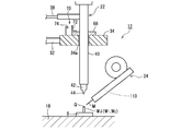
- FIG. 1 It is a figure which shows the whole structure of the joining apparatus in one Embodiment of this invention. It is a perspective view which shows the to-be-joined part of the base material in embodiment. It is a flowchart which shows the procedure of the brazing method in embodiment. It is a figure which shows one step of the torch raising / lowering operation
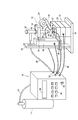
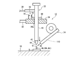
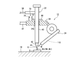
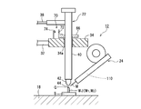
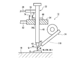
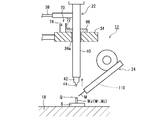
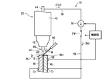
- FIG. 1 shows an overall configuration of a bonding apparatus according to an embodiment of the present invention.
- This bonding apparatus has a stationary apparatus configuration that can suitably cope with spot bonding, particularly worship bonding (butt bonding), and is a unit-type apparatus that incorporates a DC power supply circuit, a control circuit, various drive circuits, and the like.
- Brazing (brazing or brazing or using an arc) on the main body 10 and a material to be joined (base material) on an electric component support (for example, a circuit board or a circuit assembly) S under supply and control of utility from the apparatus main body 10.
- a gas cylinder 14 which is a supply source of a shielding gas, for example, argon gas.
- the joining head 12 is provided with a movable stage 18 and a torch stand 20 on a plate-like base 16, and a torch stand 20 mounted on the torch stand 20 so as to be movable up and down, and a support body independent of the torch stand 20 and the movable stage 18 (
- the filler material feeding device 24 is held at a predetermined position and orientation (not shown).
- the movable stage 18 includes an XY stage 26 for moving the electric component support S in the XY direction in the horizontal plane, and a ⁇ stage 27 for moving the electric component support S in the azimuth direction ( ⁇ direction) in the horizontal plane. And have.
- the torch stand 20 is provided with an elevating tower 30 having a built-in elevating drive unit (not shown) using, for example, a servo motor as a drive source on a fixed base 28.
- a straight drive member 34 is coupled to the lift drive unit of the lift tower 30 via a lift support shaft 32, and the torch 22 is attached to the straight drive member 34 so as to be integrally movable in the vertical direction.
- a mechanism for connecting the rectilinear drive member 34 and the torch 22 will be described in detail later.
- the torch 22 is fixed in the horizontal direction.
- the XY stage 26 and the ⁇ stage 27 perform a movement operation in the XY direction and a movement (rotation) operation in the ⁇ direction under the control signal sent from the apparatus main body 10 via the electric cable 36, respectively. It is possible to position the bonded portion WJ of the bonded material to be brazed on the mounted electrical component support S directly below the torch 22.
- the torch 22 is supplied with the power for brazing and the shielding gas SG in the present embodiment from the apparatus main body 10 via the hose 38 with a built-in electric cable, and is a cylindrical torch made of an insulator such as resin. It has a body 40 and a cylindrical or conical torch nozzle 42 attached to the lower end (tip) of the torch body 40, and a pencil-shaped torch electrode (tungsten electrode rod) 44 is placed in the torch body 40 and the torch nozzle 42. It is detachably mounted, and the lower end (tip) of the torch electrode 44 protrudes slightly (usually 2 to 3 mm) from the lower end (tip) of the torch nozzle 42.
- the apparatus main body 10 is provided with a display 46, operation buttons 48, a power switch 50 and the like on the front face of the unit in a touch panel form, and external connection terminals or connectors 52 are provided on the side or back face of the unit.
- the shield gas SG sent from the gas cylinder 14 to the hose 15 is supplied to the torch 22 via the apparatus main body 10 and the hose 38.
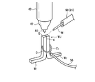
- FIG. 2 an example of the to-be-joined material (base material) which can apply the spot joining in this embodiment is shown.
- base material for example, two elongated rod-like or plate-like metal members made of copper, for example, bus bars W 1 and W 2 are used as base materials, and upper end surfaces of both metal members W 1 and W 2 ( The top surfaces of the top surfaces are substantially flush with each other, and the upper ends of the top surfaces are integrated together. The upper ends of the metal members W 1 and W 2 combined together form a joined portion WJ.
- the other end (not shown) of each metal member W 1 , W 2 communicates with an electrical component (not shown) mounted on the electrical component support S, for example.
- one terminal member W 1 is mounted on an electrical component support S
- the other end of the other terminal member W 2 is mounted on another electrical component support (not shown). (Not shown).
- a pair of contacts (contacts) C 1 and C 2 are detachably contacted with both metal members W 1 and W 2 from both the left and right sides, preferably avoiding the joined portion WJ. These contacts C 1 and C 2 are electrically connected to the positive electrode of the power supply circuit 76 (FIGS. 5A to 5E) in the apparatus main body 10 via the electric cable 56.
- the filler material feeding device 24 operates under a control signal sent from the device body 10 via the electric cable 62 so as to poke the wire-like filler material M against the supply destination (arc). It is configured to be sent out and retracted instantly.
- the filler material feeding device 24 is provided with a filler material supply amount measuring unit 110 that measures the amount of the wire-like filler material M supplied to the supply destination by one joining operation using an encoder. Yes. Detailed configurations and operations of the filler material feeding device 24 and the filler material supply amount measuring unit 110 will be described later.
- the wire-like filler material M can always be introduced and melted into the arc column or core of the arc AC without removing the wire-like filler material M. It can be considered that the entire amount of the wire-like filler metal M sent out toward the joint portion WJ is effectively used for brazing.
- the base metal members W 1 and W 2 are each a bus bar made of a tough pitch copper square bar having a cross section of 2 mm ⁇ 2 mm
- a tungsten bar having a diameter ( ⁇ ) of 2.4 mm is used for the torch electrode 44.
- the wire filler metal M for example, a phosphor copper brazing wire having a diameter ( ⁇ ) of 0.8 mm is used.
- the filler material phosphorous copper braze
- the filler material melted by arc heat in the vicinity of the top surface of the welded portion WJ is diffused by wetting, and the gap g Soaks in.
- the torch body 40 is passed through the through-hole 34 a of the plate-like rectilinear drive member 34, and the hook-like or flange-like connecting member 66 fixed to the upper part or middle part of the torch body 40 is the rectilinear drive member 34.
- the torch body 40 is coupled to the rectilinear drive member 34 such that the torch body 40 is placed on the upper surface of the straight drive member 34.
- the sensor 70 for detecting the connection or separation state between the connecting member 66 of the torch body 40 and the straight drive member 34 is provided.
- the illustrated sensor 70 is composed of a vertical linear scale, and a scale portion 72 extending in the vertical direction attached to the side surface of the connecting member 66, and the scale portion 72 according to the relative height position of the rectilinear drive member 34.
- the scale reading unit 74 is composed of a reflective optical sensor, and is electrically connected to a control circuit in the apparatus main body 10 via an electric cable (not shown).
- the control unit placed in the apparatus main body 10 can monitor the relative positional relationship between the rectilinear drive member 34 and the torch body 40 based on the output signal from the scale reading unit 74, and the rectilinear drive member 34 When the lower end of the torch electrode 44 contacts the joined portion WJ of the base material (W 1 , W 2 ) during the forward movement (downward movement), this can be detected. It should be noted that other types of sensors such as proximity sensors may be used instead of the optical sensors using such scales.
- the XY stage 26 and the ⁇ stage 27 are as described above. Positioning in the horizontal plane is performed under the control of the internal control unit.
- a preset position on the bonded portion WJ of the base materials (W 1 , W 2 ), that is, a position where the lower end of the torch electrode 44 should come into contact for energization start (hereinafter referred to as “energization start”). It is referred to as “position”.) Q is located directly below the torch electrode 44.
- the alignment operation of the open loop control can be performed.
- the gap between the filler material feeding device 24 and the bonded portion WJ is determined. But alignment is complete. That is, between the filler material feeding device 24 and the welded portion WJ, the tip of the last-stage sleeve 90 or the tip of the wire-like melt material M is on the welded portion WJ of the base material (W 1 , W 2 ).
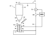
- the energization start position Q is pointed obliquely from above (FIG. 5A).
- the torch start position of the torch 22 is adjusted to an appropriate height position through the elevating tower 30 by the control unit in the apparatus main body 10 also in the height direction.
- the brazing of the next time is performed by returning the torch 22 to a certain torch start position after the end of each brazing. Therefore, the initial height position adjustment can be omitted.
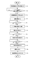
- the flowchart of FIG. 3 shows the control procedure of the control unit when one spot bonding is performed.
- the control unit includes a microcomputer, a memory, various interfaces, and the like, and controls the operation of each unit in the apparatus and the entire sequence according to a predetermined program stored or stored in the memory. Prior to the start of spot welding, the control unit sets (saves) the encoder output value LE i-1 of the filler material supply amount measuring unit 110 in FIG. 6 in a memory or a resist.
- the control unit operates the elevating drive unit of the elevating tower 30 to start the downward movement of the rectilinear drive member 34 (step S 1 ). Since the lower end of the torch electrode 44 is floating in the air (FIG. 4A), when the downward movement of the linear drive member 34 is started, the torch 22 is also driven linearly with the connecting member 66 placed on the upper surface of the linear drive member 34. It moves downward together with the member 34 (FIG. 4B).
- step S 2 When the lower end of the torch electrode 44 comes into contact with the joined portion WJ at the energization start position Q (or in the vicinity thereof with a slight deviation) (step S 2 ), the downward movement of the torch 22 ends there (FIG. 4C). Immediately thereafter, when the rectilinear drive member 34 is separated from the connecting member 66 of the torch body 40 (FIG. 4D), the control unit stops the downward movement of the rectilinear drive member 34 in response to the output signal of the sensor 70 (step S 3 ). .
- control unit starts supplying the shield gas SG during the downward movement of the torch 22 or immediately after the completion of the downward movement.
- the shield gas SG is supplied from the cylinder 14 to the torch 22 via the apparatus main body 10 and the hose 38.
- the torch 22 introduces the shield gas SG into the upper part of the torch body 40 and ejects the introduced shield gas SG from the opening of the torch nozzle 42 at a predetermined flow rate (for example, 5 liters / minute).
- the control unit starts energization under the state where the lower end of the torch electrode 44 is in contact with the energization start position Q (or the vicinity thereof) on the bonded portion WJ (step S 4 ). That is, the switch SW of the DC power supply circuit 76 composed of a constant current source is switched from the OFF state to the ON state in the apparatus main body 10. Then, the positive electrode of the DC power supply circuit 76 ⁇ the switch SW in the ON state ⁇ the electric cable 56 ⁇ the contacts C 1 and C 2 ⁇ the joined portion WJ ⁇ the torch electrode 44 ⁇ the electric cable 39 in the hose 38 ⁇ the negative electrode of the DC power supply circuit 76 A constant DC current i flows in the path or the closed circuit 78 (FIG. 5C).
- the current value of the direct current i may be kept constant from the start to the end of energization, or may be switched stepwise or continuously in the middle.
- the wire-shaped filler metal (phosphorous copper brazing) M having a melting point of 640 ° C. is rapidly melting.
- the to-be-joined part (tough pitch copper) WJ having a melting point of 1000 ° C. or higher is set to a current value I M (for example, 70 to 90 A) at which arc heat is obtained that does not melt at all or hardly.
- the current value of the current i may be controlled to a value I S that is much lower than the value I M suitable for brazing. That is, in order to extend the life of the torch electrode 44, it is preferable to generate arc discharge as weakly as possible at the moment when the tip of the torch electrode 44 is separated from the bonded portion WJ.
- an appropriate Joule heat is applied to the bonded portion WJ during energization at this stage (under the contact state). It is preferably generated and preheated.
- the current value I S at the start of energization of the current i flowing in the closed circuit 78 is controlled within a range of 10 to 20 A, for example.
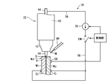
- step S 5 When the predetermined time T 1 has elapsed from the start of energization (step S 5 ), the control unit moves the linear drive member 34 slightly upward to set the lower end of the torch electrode 44 away from the bonded portion WJ (for example, 3 mm). Only upward (step S 6 ), it is stopped at that height position. At the same time as or after completion of the separation of the torch electrode 44, the control unit controls the power supply circuit 76 to set the current value of the current i flowing in the closed circuit 78 to the initial current value I S thus far. It switched to the normal current value I M for further large soldering or spot welding than (step S 7).
- the lower end of the torch electrode 44 is separated from the bonded portion WJ, and the current (arc current) i having a normal current value I M flows in the closed circuit 78, whereby the bonded portion (tough pitch copper) having a melting point of 1000 ° C. or higher.
- An arc AC capable of rapidly melting the wire-like filler metal (phosphorous copper brazing) M having a melting point of 640 ° C. with little or no melting of WJ is generated in the space gap between the torch electrode 44 and the joined portion WJ. In particular, it is generated in the space gap between the lower end of the torch electrode 44 and the energization start position Q on the bonded portion WJ.
- step S 8 the control unit starts supplying the wire-shaped filler metal M into the arc AC through the filler material feeding device 24 (step S 9 ).
- This delay time T 2 is determined in consideration of the optimum time for improving the wettability and the influence on the base material, and is usually selected in the range of 0.1 to 0.5 seconds.
- the operation of the filler material feeding device 24 is started so that the tip of the wire-like filler metal M enters the arc column of the arc AC with the just-in-time when the delay time T 2 has elapsed.
- the timing may be slightly advanced.
- the tip of the wire-like filler material M is sent from obliquely upward toward the energization start position Q on the joined portion WJ, the wire-like filler material M is surely connected to the lower end of the arc column of the arc AC. It is introduced into the part and melts quickly by receiving arc heat at the introduction position. Then, the melted filler material ⁇ M> spreads to the periphery due to the slack, and penetrates into the gap g of the bonded portion WJ or inside (see FIG. 5D).
- the melt-material supply amount measuring unit 110 is moved according to the movement (forward movement) of the wire-like melt material M.
- Encoder output value E i changes.
- the control unit sequentially captures and updates the encoder output value E i from the filler material supply amount measurement unit 110.
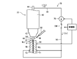
- the control unit monitors the encoder output values E i, when the increment Delta] E of the wire-shaped filler M encoder output values E i from the start of the supply of has reached the set value Delta] E S, the set amount
- the wire-like filler metal M is determined to have been supplied into the arc AC (step S 10 ), and the filler-material feeder 24 is immediately controlled to retract the wire-like filler material M from the arc AC. (Step S 11 )
- the switch SW of the power supply circuit 76 is turned off to stop energization (Step S 12 ). Immediately after that, the supply of the shielding gas SG is also stopped.
- the backward movement speed when retracting the wire filler metal M from the arc AC is set to a value several times higher (for example, 200 mm / sec) than the forward movement speed (for example, 10 to 80 mm / sec) during supply.
- the moving distance when retreating is set to 3 mm, for example.
- control unit moves the straight drive member 34 upward through the lift drive unit of the lift tower 30 and returns the torch 22 to the torch start position (step S 13 ).
- the shield gas SC is supplied around the torch electrode 44 in a state where the tip of the torch electrode 44 is in contact with the bonded portion WJ of the base material (W 1 , W 2 ). However, energization is started between the torch electrode 44 and the bonded portion WJ. Then, while continuing to supply and energize the shield gas SC, the tip of the torch electrode 44 is moved away from the joined portion WJ, and the base material (W 1 , W 2 ) is placed between the torch electrode 44 and the joined portion WJ. An arc AC is generated that can quickly melt the filler material M with little or no melting.
- the wire-like filler material M is supplied into the arc AC with a slight delay, the melt material M is melted by the heat of the arc AC, and the melted melt material ⁇ M> is diffused by wetting. Immerse in the gap g of the joint WJ. And after a certain period of time (or when the delivery amount or supply amount of the wire-like filler material M reaches the set value), the filler material M is retracted from the arc AC, and then the arc AC is extinguished, The melted (liquid) filler material ⁇ M> diffused around the gap g of the joined portion WJ and the periphery thereof is solidified.
- the arc AC generated between the torch electrode 44 and the bonded portion WJ of the base material (W 1 , W 2 ) is not the melting (arc welding) of the bonded portion WJ. Used exclusively for melting the soluble material M.
- a metal joint (joint) by brazing is obtained at the joint WJ. Therefore, for example, even if the base material (W 1 , W 2 ) is made of tough pitch copper, a blow hole as found in arc welding does not occur in principle.
- the wire-like filler material M is fed toward the position (energization start position Q) where the tip of the torch electrode 44 of the joined portion WJ is in contact, so The material M can be surely introduced into the arc column or core portion of the arc AC without being removed and can be melted most efficiently.
- the user can utilize the presented melt material supply amount measurement value as a barometer (quality management information) for assuring the quality of the spot joint.
- metal bonding formed by brazing is advantageous in terms of yield because it is easy to recover (recover) or redo even if the bonding is defective.
- the arc heat generated between the torch electrode and the base metal is much weaker, that is, the arc current is much smaller (about 1/2). It has little effect and can save power consumption.
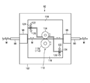
- the filler material feeding device 24 has a wire reel 80 wound around the wire-like filler material M so that the wire-like filler material M can be smoothly fed out, and the wire-like filler material M is desired from the wire reel 80.
- the sleeves 88 and 90 positioned on the downstream side of the wire moving path are attached to the filler material feeding head 92 disposed near the torch 22 and the joined portion WJ.
- the filler material feeding head 92 is attached to the thick plate-like base member 94 with the filler material guide portions or sleeves 88 and 90 of the filler material feeding device 24 via sleeve holders 96 and 98, respectively.
- a rotary encoder 112 and a filler material tip position adjusting unit 115 which are main components of the material supply amount measuring unit 110 are attached.
- the rotary encoder 112 is attached on the base member 94.
- the rotary encoder 112 may be either an incremental type or an absolute type, and a pulley or roller 112a that rotates following the movement of the wire-like filler metal M and an amount or angle of rotation of the roller 112a are encoders.
- the main body 112b has an encoder output signal generation unit (not shown) that converts it into an electrical pulse signal.
- the rotary encoder 112 is disposed on the side of the support plate 116 fixed on the base member 94.
- a pressing roller 114 disposed to face the roller 112 a of the rotary encoder 112 is attached to a movable support plate 118 that is movably disposed alongside the fixed support plate 116 on the base member 94.
- a plurality of tension coil springs 124 stretched between the support plates 116 and 118 via spring support rods 120 and 122 allow the pressing roller 114 to elastically move to the roller 112a with the wire-like filler material M interposed therebetween. Pressed.
- the wire-shaped filler metal M can move between the outer peripheral surface of the roller 112a of the rotary encoder 112 and the outer peripheral surface of the pressing roller 114 with almost no slip while receiving a large dynamic friction force.
- the rotation direction and the rotation amount of the rotary encoder 112 correspond to or are proportional to the movement direction and the movement amount of the wire filler metal M.
- an encoder output value representing the moving direction and moving amount of the wire filler metal M can be obtained from the rotary encoder 112.
- the filler material tip position adjusting unit 115 is disposed near the tip of the direct acting actuator, for example, the air cylinder 126, which is attached to the lower surface of the base member 94, and the last stage sleeve 90 of the filler material feeding device 24.
- the position sensor 128 includes an arm-shaped or frame-shaped sensor support 130 that connects the drive shaft 126 a of the air cylinder 126 and the position sensor 128. By operating the air cylinder 126 and moving the drive shaft 126a forward or backward, a standby position P O set behind the tip of the sleeve 90 on the wire moving path and a wire start position P set forward are set. The position of the position sensor 128 can be switched with S.
- Position sensor 128, the tip position of filler metal M is configured to whether it can, for example optically detected or determined to match or approximate to the nearest monitoring point, that the wire start position P S.
- the control unit in the apparatus main body 10 has a function of calculating a measured value of the filler material supply amount based on an encoder output value from the rotary encoder 112, and a wire in the filler material tip position adjusting unit 115.
- the tip of Jo filler M such as wire start position P S control function for arrived in, plays for any arithmetic function or control function in the filler metal supply amount measuring unit 110. [Operation of the filler supply amount measuring unit (adjustment of the filler material tip position)]
- FIG. 8 shows the control or calculation procedure of the control unit in the filler material tip position adjustment.
- FIG. 9 schematically shows each stage of the filler material tip position adjustment.
- the filler material tip position adjustment unit 115 under the control of the control section of the wire-like filler M tip for arrive to the wire start position P S The filler material tip position adjustment is performed.
- the backward movement distance when the wire filler metal M is retracted from the arc AC is controlled to a constant value.
- the tip of the wire-like filler material M after the end of spot welding is located somewhat forward of the tip of the sleeve 90.
- the strength and spread of the arc AC are slightly different for each spot welding, and the melting rate of the wire filler M is slightly different, so that the tip of the wire filler M after the spot welding is finished.
- the position is strictly indefinite.
- control unit reads the output value E i of the rotary encoder 112 that has been stopped after the end of spot welding (step S 20 ). Then, the control unit actuates the air cylinder 126, as shown in (b) of FIG. 9, moves the position sensor 128 which has been waiting at the standby position P O far to the wire start position P S (step S 21 ).
- step S 22 the control unit, of FIG. 9 (c), (d), the distance the wire-shaped filler metal M variable through filler metal feeder 24 in the vicinity of the wire start position P S ( ⁇ p) Only the forward movement or backward movement (step S 22 ), the process of reading and updating the output value E i of the encoder 112 after this adjustment movement (step S 23 ), and the position after the adjustment movement through the position sensor 128.
- step S 24 The process of determining whether or not the tip position of the wire-like filler material M matches or approximates the wire start position P S (step S 24 ) is repeated as appropriate, so that the tip position of the wire-like filler material M is changed to the wire. It will close gradually to the start position P S. Then, as shown in (e) of FIG.
- the control unit determines the final output value LE i of the rotary encoder 112 determined by the filler material tip position adjustment as described above, and the encoder output value set in the memory or register before the start of the current spot welding. calculates the LE i-1 and the difference (LE i -LE i-1) , the current wire feed amount measurement value LM i (step S 26). That is, this difference (LE i ⁇ LE i ⁇ 1 ) is the encoder output value LE i ⁇ when the tip position of the wire filler metal M is the same (wire start position P S ) before and after the current spot welding. 1 and LE i , which correspond to the current wire supply amount measurement value LM i .
- the control unit stores the wire feed amount measurement value LM i in the memory (storage), and displays on the display unit 46.
- the amount (length) of the wire-like filler metal M supplied to the arc between the torch electrode 44 and the joined portion WJ in the current spot joining is measured through the rotary encoder 112. Since the monitor information of the measured value of the filler material supply amount is provided to the user, the user can provide the measured value of the melt material supply amount to the barometer (quality control information) for assuring the quality of the spot joint. Can be effectively utilized as.
- a rotary encoder 112 of the melt material supply amount measuring unit 110 is provided in the melt material feed head 92 of the melt material feed device 24, and near the tip of the wire-like melt material M. Since the movement amount or supply amount of the wire-like filler material M is measured, even if the wire-like filler material M bends on the upstream side of the wire movement path, the melt-material supply amount measuring unit 110 is not affected by this time. It is possible to accurately measure the supply amount or consumption amount of the wire-like filler material M in the spot joining. [Other Embodiments or Modifications]
- a configuration in which the rotary encoder 112 of the filler material supply amount measuring unit 110 is attached to the feeding roller 82 of the filler material feeding device 24 is also possible.
- a configuration in which a servo motor is attached to the rotary encoder 112 of the filler material supply amount measuring unit 110 to drive the filler material feeding is also possible. Even in these cases, it is preferable that the filler material tip position adjusting unit 115 is attached to the filler material feeding head 92 of the filler material feeding device 24 as in the above embodiment.
- the load received by the bonded portion WJ when the torch electrode 44 comes into contact with the bonded portion WJ can be arbitrarily reduced from the own weight of the torch body 40.
- the base material (W 1 , W 2 ) is a terminal member of a small precision electronic component.
- the load received by the welded portion WJ when the torch electrode 44 comes into contact with the welded portion WJ can be arbitrarily increased from the own weight of the torch body 40.
- the spring force of the coil spring 142 can be adjusted by providing a mechanism (not shown) for adjusting the position of the spring receiving portion 140.
- the rectilinear drive member 34 may be moved linearly in an oblique direction or a horizontal direction, and the torch electrode 44 may be moved linearly in the same direction. Is possible.
- the plate-like form of the rectilinear drive member 34 in the above-described embodiment is an example, and the rectilinear drive member 34 can take a plate, block, cylinder, or frame structure of any shape.
- the connecting member 66 can take any form.
- the torch 22 is directly attached to the rectilinear drive member 34.
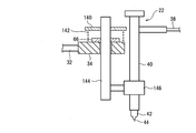
- a rectilinear movable member 144 such as an elevating rod is attached to the rectilinear drive member 34 so as to be integrally movable and separable in the vertical direction, and a torch is attached to a holder 146 coupled to the rectilinear movable member 144.
- the structure which attaches 22 so that attachment or detachment is possible is also possible.
- the filler material M when supplying the wire-like filler material M in the arc AC, it is most preferable to send the filler material M aiming at the energization start position Q on the welded portion WJ. However, it is also possible to feed the filler material M directly over the energization start position Q, that is, through the gap between the tip of the torch electrode 44 and the energization start position Q.
- the shape of the filler material M is arbitrary, and is not limited to a wire, but may be, for example, a rod or a plate.
- the joining apparatus in the above embodiment is a stationary type, a form mounted on a robot is also possible.
- the linear drive member 34 or the lifting support shaft 32 may be coupled to the robot arm.
- the filler material feeding device 24 may be mounted on the same robot together with the torch 22 or may be mounted on another robot.
- the bonding apparatus in the above embodiment includes an automatic alignment mechanism (XY stage 25, ⁇ stage 26) on the stage 18 of the bonding head 12.
- the stage 18 may be configured as a manually movable stage, or the workpiece or the electrical component support S may be manually positioned on the fixed stage 18.
- the material of the metal members W 1 and W 2 is not limited to copper or a copper alloy, and may be a conductor such as aluminum, aluminum alloy, or brass, and the material and terminals of the terminal member W 1 the material of the member W 2 may be different.
- the shape of the metal members W 1 and W 2 may be arbitrary, and for example, the metal member W 1 or W 2 is not limited to a rod or plate having a rectangular cross section, and may be a rod or plate having a circular cross section.
- the controller controls the power supply circuit 76 so as to monitor the temperature of the bonded portion WJ using a temperature sensor, for example, a radiation thermometer, and to control the monitored temperature to a constant value or a certain range. It is also possible to variably control the initial current value I S of the current i.
- the control unit monitors the temperature of the welded portion WJ through the temperature sensor while supplying the wire-like melted material M into the arc AC through the melt material feeding device 24, and
- the arc current i is controlled so that the temperature of WJ is higher than the melting point of the filler metal M and does not exceed the melting points of the base materials (W 1 , W 2 ).
- the measured temperature of the bonded portion WJ is equal to or approximates a predetermined reference temperature (for example, 750 ° C.) that is higher than the melting point of the filler metal M and lower than the melting point of the base materials (W 1 , W 2 ).
- a predetermined reference temperature for example, 750 ° C.
- the current value I M of the arc current i is increased to about 100 A, and when the measured temperature of the welded portion WJ exceeds the reference temperature, the arc current i The control for reducing the current value I M to about 10 A is repeated.
- thermocouple can be used as the temperature sensor. In that case, it is preferable to attach the contacts C 1 and C 2 (FIG. 2) rather than directly attaching the thermocouple to the bonded portion WJ.
Landscapes
- Engineering & Computer Science (AREA)
- Mechanical Engineering (AREA)
- Arc Welding In General (AREA)
Applications Claiming Priority (2)
| Application Number | Priority Date | Filing Date | Title |
|---|---|---|---|
| JP2014-068603 | 2014-03-28 | ||
| JP2014068603A JP6259341B2 (ja) | 2014-03-28 | 2014-03-28 | 接合装置 |
Publications (1)
| Publication Number | Publication Date |
|---|---|
| WO2015145509A1 true WO2015145509A1 (ja) | 2015-10-01 |
Family
ID=54194111
Family Applications (1)
| Application Number | Title | Priority Date | Filing Date |
|---|---|---|---|
| PCT/JP2014/006292 Ceased WO2015145509A1 (ja) | 2014-03-28 | 2014-12-17 | 接合装置 |
Country Status (2)
| Country | Link |
|---|---|
| JP (1) | JP6259341B2 (enExample) |
| WO (1) | WO2015145509A1 (enExample) |
Cited By (3)
| Publication number | Priority date | Publication date | Assignee | Title |
|---|---|---|---|---|
| CN105834539A (zh) * | 2016-03-03 | 2016-08-10 | 恩捷斯智能系统(深圳)有限公司 | 一种智能点焊机 |
| CN110802294A (zh) * | 2019-11-14 | 2020-02-18 | 湖南弘钧电子科技有限公司 | 自动焊锡机 |
| CN116060725A (zh) * | 2023-03-09 | 2023-05-05 | 西安鼎瑞电子科技有限公司 | 连接器焊接辅助设备 |
Families Citing this family (3)
| Publication number | Priority date | Publication date | Assignee | Title |
|---|---|---|---|---|
| WO2017130911A1 (ja) * | 2016-01-27 | 2017-08-03 | 株式会社アマダミヤチ | Tig溶接装置 |
| CN106312226B (zh) * | 2016-09-30 | 2019-05-10 | 深圳优米赫机器人工业有限公司 | 一种自动焊锡机器人 |
| WO2025146820A1 (ja) * | 2024-01-05 | 2025-07-10 | 国立大学法人大阪大学 | はんだ付け装置および非一時的なコンピュータ可読媒体 |
Citations (10)
| Publication number | Priority date | Publication date | Assignee | Title |
|---|---|---|---|---|
| JPH02155573A (ja) * | 1988-12-06 | 1990-06-14 | Ishikawajima Harima Heavy Ind Co Ltd | Tig溶接方法並びにtig溶接設備 |
| JPH05237657A (ja) * | 1992-02-27 | 1993-09-17 | Sansha Electric Mfg Co Ltd | 直流tigアーク溶接機 |
| JPH07276049A (ja) * | 1994-03-31 | 1995-10-24 | Nisshin Steel Co Ltd | 溶接管の製造装置 |
| JPH0866764A (ja) * | 1994-08-31 | 1996-03-12 | Matsushita Electric Ind Co Ltd | はんだ付け装置 |
| JPH10305365A (ja) * | 1997-05-06 | 1998-11-17 | Olympus Optical Co Ltd | プラズマロー付け方法 |
| JP2001071125A (ja) * | 1999-09-03 | 2001-03-21 | Omc Kk | ハンダ付け方法とその装置 |
| JP2004216426A (ja) * | 2003-01-15 | 2004-08-05 | Japan Unix Co Ltd | はんだ送り装置 |
| US20100096436A1 (en) * | 2008-10-22 | 2010-04-22 | Lincoln Global, Inc. | Semi-automatic brazing device |
| JP2010131668A (ja) * | 2008-10-27 | 2010-06-17 | Kazuhito Kito | 溶接装置 |
| JP2012135774A (ja) * | 2010-12-24 | 2012-07-19 | Nippon Avionics Co Ltd | はんだ供給装置 |
Family Cites Families (1)
| Publication number | Priority date | Publication date | Assignee | Title |
|---|---|---|---|---|
| JP3515962B2 (ja) * | 2001-03-30 | 2004-04-05 | 株式会社大進工業研究所 | ろう付装置 |
-
2014
- 2014-03-28 JP JP2014068603A patent/JP6259341B2/ja active Active
- 2014-12-17 WO PCT/JP2014/006292 patent/WO2015145509A1/ja not_active Ceased
Patent Citations (10)
| Publication number | Priority date | Publication date | Assignee | Title |
|---|---|---|---|---|
| JPH02155573A (ja) * | 1988-12-06 | 1990-06-14 | Ishikawajima Harima Heavy Ind Co Ltd | Tig溶接方法並びにtig溶接設備 |
| JPH05237657A (ja) * | 1992-02-27 | 1993-09-17 | Sansha Electric Mfg Co Ltd | 直流tigアーク溶接機 |
| JPH07276049A (ja) * | 1994-03-31 | 1995-10-24 | Nisshin Steel Co Ltd | 溶接管の製造装置 |
| JPH0866764A (ja) * | 1994-08-31 | 1996-03-12 | Matsushita Electric Ind Co Ltd | はんだ付け装置 |
| JPH10305365A (ja) * | 1997-05-06 | 1998-11-17 | Olympus Optical Co Ltd | プラズマロー付け方法 |
| JP2001071125A (ja) * | 1999-09-03 | 2001-03-21 | Omc Kk | ハンダ付け方法とその装置 |
| JP2004216426A (ja) * | 2003-01-15 | 2004-08-05 | Japan Unix Co Ltd | はんだ送り装置 |
| US20100096436A1 (en) * | 2008-10-22 | 2010-04-22 | Lincoln Global, Inc. | Semi-automatic brazing device |
| JP2010131668A (ja) * | 2008-10-27 | 2010-06-17 | Kazuhito Kito | 溶接装置 |
| JP2012135774A (ja) * | 2010-12-24 | 2012-07-19 | Nippon Avionics Co Ltd | はんだ供給装置 |
Cited By (3)
| Publication number | Priority date | Publication date | Assignee | Title |
|---|---|---|---|---|
| CN105834539A (zh) * | 2016-03-03 | 2016-08-10 | 恩捷斯智能系统(深圳)有限公司 | 一种智能点焊机 |
| CN110802294A (zh) * | 2019-11-14 | 2020-02-18 | 湖南弘钧电子科技有限公司 | 自动焊锡机 |
| CN116060725A (zh) * | 2023-03-09 | 2023-05-05 | 西安鼎瑞电子科技有限公司 | 连接器焊接辅助设备 |
Also Published As
| Publication number | Publication date |
|---|---|
| JP6259341B2 (ja) | 2018-01-10 |
| JP2015188917A (ja) | 2015-11-02 |
Similar Documents
| Publication | Publication Date | Title |
|---|---|---|
| JP6259341B2 (ja) | 接合装置 | |
| JP6113087B2 (ja) | Tig溶接装置 | |
| JP6285724B2 (ja) | 接合方法及び接合装置 | |
| CN100457356C (zh) | 控制和/或调节焊接过程的方法 | |
| JP6112916B2 (ja) | Tig溶接装置 | |
| CN106475649A (zh) | 一种激光焊锡机 | |
| JP2016059927A (ja) | 半田鏝 | |
| KR100866650B1 (ko) | 전기저항용접기 | |
| JP5996372B2 (ja) | 端子部材溶接方法 | |
| JP6302343B2 (ja) | Tig溶接装置及びtig溶接方法 | |
| JP5778942B2 (ja) | 片側スポット溶接装置 | |
| JP6393066B2 (ja) | Tig溶接方法及びtig溶接装置 | |
| JP7245935B2 (ja) | Tig溶接方法及びtig溶接装置 | |
| TW464584B (en) | Soldering method and device therefor | |
| JP2011529397A (ja) | 溶接ワイヤーの端部を成形する方法および装置 | |
| JP3211580B2 (ja) | はんだ付け装置 | |
| CN102319946A (zh) | 具有双点焊头的电子点焊机 | |
| KR20010030220A (ko) | 납땜 방법과 그 장치 | |
| JP2003025065A (ja) | ろう付方法およびろう付装置 | |
| JP6089193B2 (ja) | 半田処理装置 | |
| GB2271305A (en) | Reflow soldering process control | |
| JP5189896B2 (ja) | 溶接装置及び溶接方法 | |
| JP2010073788A (ja) | 被覆線の半田付け方法および半田付け装置 | |
| CN117506075A (zh) | 一种可调节式热电偶焊接装置及焊接方法 | |
| JPS6160597B2 (enExample) |
Legal Events
| Date | Code | Title | Description |
|---|---|---|---|
| 121 | Ep: the epo has been informed by wipo that ep was designated in this application |
Ref document number: 14886883 Country of ref document: EP Kind code of ref document: A1 |
|
| NENP | Non-entry into the national phase | ||
| 122 | Ep: pct application non-entry in european phase |
Ref document number: 14886883 Country of ref document: EP Kind code of ref document: A1 |