WO2015129174A1 - 回転ハンドル用キャップ - Google Patents
回転ハンドル用キャップ Download PDFInfo
- Publication number
- WO2015129174A1 WO2015129174A1 PCT/JP2015/000564 JP2015000564W WO2015129174A1 WO 2015129174 A1 WO2015129174 A1 WO 2015129174A1 JP 2015000564 W JP2015000564 W JP 2015000564W WO 2015129174 A1 WO2015129174 A1 WO 2015129174A1
- Authority
- WO
- WIPO (PCT)
- Prior art keywords
- exterior body
- interior
- side uneven
- cap
- uneven portion
- Prior art date
- Legal status (The legal status is an assumption and is not a legal conclusion. Google has not performed a legal analysis and makes no representation as to the accuracy of the status listed.)
- Ceased
Links
Images



Classifications
-
- F—MECHANICAL ENGINEERING; LIGHTING; HEATING; WEAPONS; BLASTING
- F16—ENGINEERING ELEMENTS AND UNITS; GENERAL MEASURES FOR PRODUCING AND MAINTAINING EFFECTIVE FUNCTIONING OF MACHINES OR INSTALLATIONS; THERMAL INSULATION IN GENERAL
- F16K—VALVES; TAPS; COCKS; ACTUATING-FLOATS; DEVICES FOR VENTING OR AERATING
- F16K35/00—Means to prevent accidental or unauthorised actuation
- F16K35/02—Means to prevent accidental or unauthorised actuation to be locked or disconnected by means of a pushing or pulling action
-
- F—MECHANICAL ENGINEERING; LIGHTING; HEATING; WEAPONS; BLASTING
- F16—ENGINEERING ELEMENTS AND UNITS; GENERAL MEASURES FOR PRODUCING AND MAINTAINING EFFECTIVE FUNCTIONING OF MACHINES OR INSTALLATIONS; THERMAL INSULATION IN GENERAL
- F16K—VALVES; TAPS; COCKS; ACTUATING-FLOATS; DEVICES FOR VENTING OR AERATING
- F16K31/00—Actuating devices; Operating means; Releasing devices
- F16K31/44—Mechanical actuating means
-
- F—MECHANICAL ENGINEERING; LIGHTING; HEATING; WEAPONS; BLASTING
- F16—ENGINEERING ELEMENTS AND UNITS; GENERAL MEASURES FOR PRODUCING AND MAINTAINING EFFECTIVE FUNCTIONING OF MACHINES OR INSTALLATIONS; THERMAL INSULATION IN GENERAL
- F16K—VALVES; TAPS; COCKS; ACTUATING-FLOATS; DEVICES FOR VENTING OR AERATING
- F16K31/00—Actuating devices; Operating means; Releasing devices
- F16K31/44—Mechanical actuating means
- F16K31/60—Handles
-
- F—MECHANICAL ENGINEERING; LIGHTING; HEATING; WEAPONS; BLASTING
- F16—ENGINEERING ELEMENTS AND UNITS; GENERAL MEASURES FOR PRODUCING AND MAINTAINING EFFECTIVE FUNCTIONING OF MACHINES OR INSTALLATIONS; THERMAL INSULATION IN GENERAL
- F16K—VALVES; TAPS; COCKS; ACTUATING-FLOATS; DEVICES FOR VENTING OR AERATING
- F16K35/00—Means to prevent accidental or unauthorised actuation
- F16K35/04—Means to prevent accidental or unauthorised actuation yieldingly resisting the actuation
-
- F—MECHANICAL ENGINEERING; LIGHTING; HEATING; WEAPONS; BLASTING
- F16—ENGINEERING ELEMENTS AND UNITS; GENERAL MEASURES FOR PRODUCING AND MAINTAINING EFFECTIVE FUNCTIONING OF MACHINES OR INSTALLATIONS; THERMAL INSULATION IN GENERAL
- F16K—VALVES; TAPS; COCKS; ACTUATING-FLOATS; DEVICES FOR VENTING OR AERATING
- F16K51/00—Other details not peculiar to particular types of valves or cut-off apparatus
-
- F—MECHANICAL ENGINEERING; LIGHTING; HEATING; WEAPONS; BLASTING
- F16—ENGINEERING ELEMENTS AND UNITS; GENERAL MEASURES FOR PRODUCING AND MAINTAINING EFFECTIVE FUNCTIONING OF MACHINES OR INSTALLATIONS; THERMAL INSULATION IN GENERAL
- F16K—VALVES; TAPS; COCKS; ACTUATING-FLOATS; DEVICES FOR VENTING OR AERATING
- F16K7/00—Diaphragm valves or cut-off apparatus, e.g. with a member deformed, but not moved bodily, to close the passage ; Pinch valves
Definitions
- the present invention relates to a cap for a rotary handle, and more particularly, can be easily attached to a rotary handle even in a narrow space, and can be rotated together with the rotary handle by a simple operation after being attached to the rotary handle.
- the present invention relates to a rotating handle cap that can be switched between a co-rotating state and an independent rotating state that can rotate independently of the rotating handle.
- Patent Document 1 a valve handle cover relating to “preventing erroneous operation of a valve handle in a mechanical equipment part” has been proposed.
- valve handle cover described in Patent Document 1 has a box shape in which the valve handle 1 can be entirely received, as is apparent from the drawing in Patent Document 1.
- the valve is halved in the diametrical direction of the valve, and "the two boxes with the cut shape are hinged on one side of the thickness of the valve handle", and the two boxes are opened and closed around the hinge. It becomes.
- the valve handle cover 2 opens the two boxes around the hinge, puts the handle in the two expanded boxes, and then closes the two boxes. As a result, a state in which the handle is accommodated in the handle cover 2 is realized.
- the valve handle cover has a structure that “the two box-shaped ones have a keyhole and are locked using the keyhole”.
- valve handle cover described in Patent Document 1 Since the valve handle cover described in Patent Document 1 must open and close left and right around the hinge when storing the valve, a wide space is ensured in a space orthogonal to the axis of the valve. Must. Therefore, there is a technical problem that the valve handle cover cannot be mounted on the valve unless a sufficiently large space is secured around the valve to mount the valve handle cover.
- Patent Document 2 discloses a lock device for a channel opening / closing handle.
- This locking device is a "stopper support (12) having a through hole (19) (23) for body insertion for fitting the fluid controller body (5) and fixed to the fluid controller body (5). (22) and a stopper (12) that is provided on the stopper support (12) (22) so as not to rotate and engages with the channel opening / closing handle (8) to prevent the channel opening / closing handle (8) from rotating. 16) and (26) ”(see claim 1 of Patent Document 2).
- Patent Document 2 is “an apparatus that locks the flow path opening / closing handle (8) in the fully open or fully closed position” (see claim 1 of Patent Document 2). It has a structure that actively prevents movement.
- Patent Document 3 discloses a rotary valve.
- the rotary valve is "fixed with a locking mechanism, and can be avoided to avoid erroneous operation .... Even if it is installed in a narrow space, it does not hinder the rotation of the handle, and the same valve book It is a rotary valve that can be easily changed with or without a lock mechanism by simply replacing the handle using the main body, and that can be held and fixed at a reliable switching position for opening / closing and switching the flow path ”( (See paragraph number 0001 of Patent Document 3).
- This Patent Document 3 discloses a mechanism that makes the stem of the valve body, that is, the rotation shaft unrotatable.
- Patent Document 4 states that “a stopper (26) is provided with a fully-opened rotation blocking portion (31) for blocking the rotation of the handle in the fully open position and a fully closed rotation blocking for blocking the rotation of the handle in the fully closed position. And a fluid control device provided with a portion (32) "(see claim 1 of Patent Document 4). This fluid controller has a structure that prevents the handle from rotating in the fully open position and the fully closed position.
- valve is fixed to the handle of the rotating shaft of the valve, and is slidably fitted inside a guide tube arranged to rotate integrally with the handle.
- a valve locking device having a locking bar that can be extended from a lower end opening and a strike that locks the lowered locking bar is disclosed. This locking device is based on the principle of positively restricting the movement of the rotation operation shaft so that the rotation operation shaft does not move.
- Patent Document 6 discloses a cover support member (12) fixed to the fluid controller body 2, a cylindrical handle cover (13) that covers the flow path opening / closing handle (3) and is received by the cover support member,
- An erroneous operation preventing device (11) comprising a coupling means (14) for detachably coupling the cover support member (12) and the handle cover (13) is disclosed.
- This erroneous operation preventing device (11) has a structure in which the flow path opening / closing handle (3) cannot be rotated unless the lock (24) is removed using a key.
- Patent Document 7 states that “a device for locking a flow path opening / closing handle (8) rotated with respect to a fluid controller main body (5) in a fully opened or fully closed position, which includes a through hole (19) for inserting a main body. Stopper support (12) (22) having (23) and fixed to fluid controller main body (5), and stopper indicator (12) (22) provided non-rotatably and open / close flow path “A locking device for a flow path opening / closing handle of a fluid controller having stoppers (16), (26) that engage with the handle (8) and prevent its rotation” (see claim 1 of Patent Document 7). are disclosed.
- Patent Documents 1 to 7 have a mechanism that prevents the rotation axis of the flow path opening / closing handle from rotating.
- the problem to be solved by the present invention is that it can be easily mounted on the rotary handle without requiring a large space for mounting on the rotary handle that controls the opening and closing of the valve.
- Another object of the present invention is to provide a cap for a rotating handle that can realize a rotatable state and a rotatable state independent of the rotating handle by a simple operation.
- a cap for a rotary handle that is attached to a rotary shaft and that is attached to a rotary handle that rotates the rotary shaft An interior body that is mounted so as to be fixed to the rotary handle, an exterior body that interiors the interior body, and the exterior body that is rotatable and rotatable about the rotation axis of the exterior body with respect to the interior body
- a rotating handle cap comprising: a disabling clutch portion; and a holding portion that holds a rotatable state of the exterior body that is rotatable with respect to the interior body by the clutch portion;
- the clutch portion is formed on an inner body side uneven portion formed on an edge portion of the inner body toward the outer body, and on a surface of the outer body toward the inner body, and on the inner body side.
- the cap for a rotating handle according to the above (1) comprising an exterior body side uneven portion arranged to engage with the uneven portion, (3) When the holding portion engages the interior body side uneven portion and the exterior body side uneven portion, the holding portion retracts from the interior body side uneven portion and the exterior body side uneven portion, and the interior body side uneven portion and the exterior body side
- the cap for a rotary handle according to the above (2) which is a mover interposed between the interior body side uneven portion and the exterior body side uneven portion when separating the uneven portion.
- the cap for the rotary handle can be mounted on the rotary handle by mounting the interior body on the rotary handle along the direction of the rotary shaft of the rotary handle. A space extending in a direction orthogonal to the direction is not required for mounting.
- the exterior body can be rotated about the rotation axis of the exterior body with respect to the interior body by the clutch portion, and the exterior body can be rotated with respect to the interior body by the holding portion. Even if a rotational force is applied to the interior body, the rotation generated in the exterior body is not transmitted to the interior body, and therefore, it is possible to realize a state in which only the exterior body rotates relative to the interior body.
- the rotary handle also rotates. At this time, since the diameter of the exterior body is larger than that of the rotary handle, the rotary handle can be easily rotated with a smaller rotational force.
- the clutch portion is formed on an inner body side uneven portion formed on an edge of the inner body toward the outer body, on a surface of the outer body toward the inner body, and the Since the exterior body side uneven portion arranged to engage with the interior body side uneven portion is provided, the engagement of the interior body side uneven portion and the exterior body side uneven portion ensures that the rotational force of the exterior body is applied to the interior body. Therefore, when the exterior body is rotated, a cap for a rotary handle can be provided in which the exterior body does not rotate idly by not transmitting part or all of the rotational force of the exterior body to the interior body.
- the holding part when the holding part engages the interior body side uneven part and the exterior body side uneven part, the holding part retracts from the interior body side uneven part and the exterior body side uneven part, and the interior body side uneven part and the When separating the exterior body side uneven portion, since the mover is interposed between the interior body side uneven portion and the exterior body side uneven portion, the interior body side uneven portion and the exterior are simply moved forward and backward. A state in which the body-side uneven portion is engaged and a state in which the interior body-side uneven portion and the exterior body-side uneven portion are separated can be easily realized.
- FIG. 1 is an explanatory view showing a state in which a rotating handle cap according to an embodiment of the present invention is mounted on a fluid controller, and the exterior body rotates together with the interior body with respect to the interior body by a clutch portion.
- FIG. 2 is an explanatory view showing a state in which a rotating handle cap according to an embodiment of the present invention is attached to a fluid controller, and the exterior body rotates with respect to the interior body by the clutch portion independently of the interior body. is there.
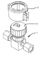
- FIG. 3 is a perspective view showing a state in which a rotating handle cap according to an embodiment of the present invention is attached to a fluid controller.
- FIG. 4 is a perspective view showing a state where the rotary handle cap is removed from the fluid controller.
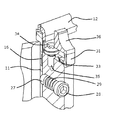
- FIG. 5 is a partially enlarged partial cutaway view showing a holding portion in a state in which the exterior body is rotatable with respect to the interior body by the clutch portion in the cap for the rotary handle according to the embodiment of the present invention.
- FIG. 6 is a partially enlarged partial cutaway view showing the holding portion in a state where the outer body cannot be rotated with respect to the inner body by the clutch portion in the cap for the rotating handle according to the embodiment of the present invention.
- the fluid controller 1 is a known diaphragm valve, for example, and includes a fluid controller body (also referred to as a body) having an inlet pipe joint portion 3 and an outlet pipe joint portion 4. 2, a substantially cylindrical bonnet 5 fitted over the fluid controller body 2, a bonnet nut 6 for fixing the bonnet 5 to the fluid controller body 2, and the hood 5.
- a diaphragm (not shown) that blocks or releases the communication between the inlet passage and the outlet passage in the fluid controller main body 2 in accordance with the vertical movement of the rod is provided.
- the inlet pipe joint portion 3 extends so as to protrude to one side of the fluid controller body 2, for example, to the left, and the outlet pipe joint portion 4 extends to the other side of the fluid controller body 2, for example, Extends to the right.
- the rotary handle 8 is formed in a cylindrical shape having a substantially circular upper surface when viewed from the plane, that is, when viewed from the central axis direction of the rotary shaft that is the valve stem, and a peripheral side surface extending along the central axis direction from the edge of the upper surface.
- a plurality of concave grooves 8 ⁇ / b> A that are formed vertically along the central axis direction are formed at predetermined intervals.
- the concave groove 8A serves as an anti-slip for fingers when the rotary handle 8 is rotated.
- the rotary handle 8 turns the rotary handle 8 clockwise or counterclockwise to open or close the flow path in the inlet pipe joint 3 and the flow path in the outlet pipe joint 4. be able to.
- a rotating handle cap 10 according to an embodiment of the present invention includes an interior body 11 and an exterior body 12.
- the interior body 11 is formed in a cylindrical body that opens at both ends.
- the inner diameter of the opening at one end of the cylindrical body of the interior body 11 is determined so that the rotary handle 8 can be fitted inside the cylindrical body.
- the dimension of the cylindrical body 11 in the direction of the central axis is such that when the rotary handle 8 is fitted in the interior of the interior body 11, the edge of the one end opening of the interior body 11 is It is determined so as to be slightly longer than the edge of the lower surface of the lower end portion of the rotary handle 8.
- the material forming the interior body 11 is determined so that when the interior body 11 is rotated, the rotary handle 8 is also rotated.
- the rotary handle 8 can be mounted inside the interior body 11 by being pushed into the interior body 11, and when the rotary handle 8 has been installed,
- the inner body 11 can be formed of an appropriate material having elasticity that can be tightened by the inner peripheral surface and rigidity that can rotate the rotating handle 8 smoothly when the inner body 11 is rotated.
- the interior body 11 is formed of a material having appropriate elasticity and rigidity, the interior body 11 tightens the rotary handle 8 housed in the interior body 11 with an elastic force due to the elasticity of the interior body 11.
- the rotary handle 8 is rotated according to the rotation of the interior body 11 by having an appropriate rigidity, the interior body 11 is not deformed by the rotational force.
- the “rotating handle” can be formed to rotate clockwise and counterclockwise, and to rotate at a predetermined angle in the clockwise and counterclockwise directions.
- the interior body 11 is formed of an appropriate material having low elasticity and rigidity, although not shown, it is formed on the outer peripheral surface of the rotary handle 8 in parallel with the central axis.
- a locking key that can be fitted into the locking groove is formed on the inner peripheral surface of the inner body 11, thereby providing a rigid inner body 11.
- the rotary handle 8 can be smoothly rotated.
- not only the combination of the locking groove and the locking key but also a mechanical configuration capable of rotating the rotary handle 8 when the interior body 11 is rotated can be appropriately employed. .
- the rotary handle 8 can be smoothly inserted into or fitted into the internal space of the interior body 11 by pushing the interior body 11 along the central axis of the rotary handle 8. Unless the interior body 11 is largely deformed by the rotation of the rotary handle 8, the material of the interior body 11 can be appropriately determined, and the rotation of the rotary handle 8 and the rotation of the interior body 11 are performed simultaneously. A mechanical coupling structure that can be used can be appropriately employed.
- the end edge 13 facing the exterior body 12 that interiors the interior body 11 is formed in an annular shape centering on the central axis, and the interior body side unevenness toward the exterior body 12 Part 14 is formed.
- the interior body side uneven portion 14 is centered on the central axis of the interior body 11 provided between the ridge line that coincides with the radial line centered on the central axis of the interior body 11 and the ridge line adjacent to the ridge line. Concavities and convexities 15 in which peaks and valleys are alternately repeated are formed with valley lines that coincide with the radius line.
- the interior body-side uneven portion 14 formed in a disc shape has a circular opening. When the rotary handle 8 is installed in the interior body 11, the surface of the rotary handle 8 is exposed at the opening.
- a positioning recess 16 is provided on the outer peripheral surface of the cylindrical body in the interior body 11 so as to make a round around the outer peripheral surface with the central axis as a center.
- the exterior body 12 has a cylindrical body portion 17 and an annular disk body 18 formed in a cylindrical shape so as to open both ends.
- the edge portion 19 has an inner end 20 that opens in a circular shape so as to expose an end face of the rotary handle 8 that is mounted by fitting or insertion into the interior body 11 housed in the exterior body 12. If the inner diameter of the inner end 20 is designed to be the same as the opening diameter of the other end opening of the inner body 11, the inner peripheral surface of the inner end 20 and the inner peripheral surface of the other end opening of the inner body 11 are designed. And the end face of the internal rotary handle 8 can be observed without hindrance.
- This annular disk 18 is provided with a mounting projection 21 on its upper end surface.
- the annular disc body 18 is fixed to the edge portion 19 by inserting the attachment protrusion 21 into an attachment hole 22 formed through the annular edge portion 19 formed at the other end of the cylindrical body portion 17. It is installed.
- the exterior body side uneven part 23 is formed on the surface of the annular disk 18 opposite to the surface on which the mounting projection 21 is provided, in other words, on the surface of the annular disk 18 facing the interior body 11 when the exterior body 12 is interiorized.
- the exterior body side uneven part 23 is formed.
- This exterior body side uneven part 23 is centered on the central axis of the exterior body 12 provided between a ridge line that coincides with a radial line centered on the central axis of the exterior body 12 and an adjacent ridge line.
- the projections and recesses 24 have peaks and valleys that are alternately repeated with valley lines that coincide with the radius lines.
- the unevenness 24 in the exterior body side uneven portion 23 is formed so as to mesh with the unevenness 15 in the interior body side uneven portion 14 formed in the interior body 11.
- the inner body side uneven portion 14 and the outer body side uneven portion 23 form a clutch portion 25.
- a ball mounting hole 26 penetrating from the outer surface to the inner peripheral surface is opened on the peripheral side surface of the cylindrical body portion 17 in the exterior body 12.
- the ball mounting holes 26 are spaced on the peripheral side surface of the cylindrical body portion 17 in a virtual plane orthogonal to the central axis line of the cylindrical body portion 17 so that the central angle about the central axis line is, for example, 90 degrees. And four are provided.
- the number of ball mounting holes 26 provided on the peripheral side surface of the cylindrical body portion 17 is not limited to four and may be two or three. As shown in FIGS. 1 and 2, the two ball mounting holes 26 have the same shape, and a single ball 27 is accommodated in the ball mounting hole 26.
- the ball 27 is urged toward the internal space of the cylindrical body portion 17 by an urging member, for example, a coil spring 29, attached to an attachment closing member 28 attached to the opening on the outer peripheral surface side of 17.
- the ball 27 is urged by the coil spring 29, but the opening on the inner peripheral surface side of the cylindrical portion 17 of the ball mounting hole 26 has a diameter inside the ball mounting hole 26. Since the diameter is slightly smaller than the above, the ball 27 is not detached from the opening on the inner peripheral surface side of the cylindrical body portion 17.
- the ball mounting hole 26 is formed in a hole penetrating from the peripheral side surface of the exterior body 12 to the inner peripheral surface.
- the balls 27 urged by the coil spring 29 press the outer peripheral surface of the interior body 11. Yes.
- the exterior body 12 is moved along the central axis direction so as to pull out the exterior body 12 from the interior body 11, the ball 27 rolls on the outer peripheral surface of the interior body 11 along with the movement of the exterior body 12.
- a part of the ball 27 fits into the positioning recess 16.
- the outer body 12 can be further pulled out of the inner body 11 as long as the urging force of the coil spring 29 is larger than the force for pulling out the outer body 12 from the inner body 11.
- the body 12 cannot be pulled out from the interior body 11, and the state where the interior body 11 is housed inside the exterior body 12 is maintained.
- the exterior body 12 can be smoothly rotated or rotated around the central axis on the outer peripheral surface of the interior body 11 with respect to the interior body 11. It is formed so that it can go straight along smoothly.
- the material of the exterior body 12 can smoothly move the inner peripheral surface of the exterior body 12 with respect to the outer peripheral surface of the interior body 11. In order to do so, the material is appropriately selected from materials having low sliding friction.
- the exterior body 12 is provided with a holding portion 30 which is an embodiment of the present invention.
- the holding unit 30 engages the interior body side uneven part 14 and the exterior body side uneven part 23 and, for example, engages the interior body side uneven part 14 and the exterior body side uneven part. 23, and when separating the interior body side uneven portion 14 and the exterior body side uneven portion 23, a mover interposed between the interior body side uneven portion 14 and the exterior body side uneven portion 23, for example, Pin 31.
- the pin 31 is arranged on the outer peripheral surface of the exterior body 12 on the upper end surface of an attachment member formed so as to protrude from the outer peripheral surface, for example, the attachment base 32.
- the mounting base 32 is formed on the outer peripheral surface of the exterior body 12 so as to protrude in a box shape.
- the pin 31 is disposed so as to be able to move forward and backward on the upper surface of the mounting base 32.
- the pin 31 is formed on the guide groove 34 extending along the radial direction of the exterior body 12 and on the bottom surface of the guide groove 34, and from the guide groove 34 to the bottom surface of the pin 31.
- a through hole 33 formed as a long hole.
- a fixing screw 35 is inserted into the guide groove 34 through the through hole 33, and the fixing screw 35 is fixed to the mounting base 32 on which the pin 31 is disposed by, for example, screwing. Therefore, the pin 31 is formed so as not to be detached from the mounting base 32 by the fixing screw 35.
- the length of the pin 31 in the forward / rearward movement direction when the pin 31 moves forward / backward and the length of the guide groove 34 in the forward / backward movement direction are determined when the pin 31 moves forward on the upper surface of the mounting base 32. Further, the tip portion of the pin 31 is located between the exterior body side uneven portion 23 and the interior body side uneven portion 14 disposed opposite to the exterior body side uneven portion 23, and the pin 31 is attached to the mounting body side uneven portion 23.
- the tip of the pin 31 is from the gap between the exterior body side uneven portion 23 and the interior body side uneven portion 14 disposed opposite to the exterior body side uneven portion 23. It is determined appropriately so as to be in the retracted position.
- the operation piece 36 is provided on the pin 31.
- the operation piece 36 is formed such that, for example, the pin 31 can be easily moved forward and backward by pressing the pin 31 with a finger and pinching the operation piece 36.
- the cap 10 for the rotating handle operates as follows.
- the rotary handle cap 10 is initially in a state in which the interior body 11 is housed inside the exterior body 12 and the interior body side uneven portion 14 and the exterior body side uneven portion 23 are engaged with each other.
- the interior body 11 and the exterior body 12 are integrated.
- a rotary handle cap 10 is attached to the rotary handle 8 of the fluid controller 1.
- the operation of attaching the rotating handle cap 10 is simple. This is because the rotary handle cap 10 is arranged with respect to the rotary handle 8 so that the central axis of the rotary handle 8 and the central axis of the rotary handle cap 10 are substantially common. Then, the rotation handle cap 10 is caused to move straight along the central axis with respect to the rotation handle 8. In short, the rotary handle cap 10 is pushed so that the rotary handle 8 is housed inside the rotary handle cap 10.
- the outer peripheral surface of the rotary handle 8 is in contact with the inner peripheral surface of the interior body 11 as shown in FIGS. Further, the interior body side uneven portion 14 and the exterior body side uneven portion 23 are engaged with each other, and the rotary handle 8 is mounted in the interior body 11. Under this state, when the exterior body 12 is rotated about its central axis, the rotary handle 8 is also rotated. At this time, since the diameter of the exterior body 12 is larger than that of the rotary handle 8, the rotary handle 8 can be rotated with a small rotational force.
- the exterior body 12 is grasped and the exterior body 12 is pulled from the interior body 11 along the central axis direction of the interior body 11. Even if the inner peripheral surface of the exterior body 12 and the outer peripheral surface of the interior body 11 are in contact with each other, the balls 27 roll on the outer periphery surface of the interior body 11, so that the exterior body 12 is pulled out of the interior body 11.
- the exterior body 12 can be moved straight without resistance.
- the ball 27 is fitted into the positioning recess 16.
- the feeling of impact when the ball 27 is fitted is transmitted to the finger operating the exterior body 12, so the operator further pulls the exterior body 12 out of the interior body 11. Stop operation. Even if the operator performs an operation of further pulling out the exterior body 12 from the interior body 11 in spite of a sense of impact, the ball 27 is fitted in the positioning recess 16. No more can be extracted from the body 11.
- the holding unit 30 is in an initial state in which the pin 31 is retracted from the interior body side uneven portion 14 and the exterior body side uneven portion 23 as shown in FIG.
- the operation piece 36 is pressed toward the exterior body 12 by pressing the operation piece 36 with a finger or the like.
- the pin 31 integrally connected to the pressed operation piece 36 moves forward.
- the interior body side uneven portion 14 and the exterior body side uneven portion 23 are separated with a gap, so that the pin 31 enters the gap.
- the fixing screw 35 is attached to the guide groove 34 which is a long hole in the pin 31, the pin 31 advances further by the head of the fixing screw 35 coming into contact with the inner wall of the guide groove 34. There is no.
- the tip of the pin 31 enters a space between the interior body side uneven portion 14 and the exterior body side uneven portion 23.
- the pin 31 When the tip of the pin 31 is inserted in the space between the interior body side uneven portion 14 and the exterior body side uneven portion 23, the pin 31 is interposed in the space between the interior body side uneven portion 14 and the exterior body side uneven portion 23. As a result, the exterior body 12 cannot move to the interior body 11 along its central axis. In addition, since a part of the ball 27 is fitted in the positioning recess 16 provided on the outer surface of the interior body 11, the exterior body 12 can rotate with respect to the interior body 11.
- the exterior body 12 is rotatable with respect to the interior body 11, for example, even if a rotational force is applied to the exterior body 12 for some reason, the exterior body 12 rotates but the interior body 11 is Does not rotate.
- the rotary handle 8 may rotate when some rotational force or impact is applied to the rotary handle 8.
- the rotary handle cap 10 is attached to the rotary handle 8 even if any rotational force or impact is applied to the exterior body 12, the exterior body 12 only rotates at that time, and the interior body 11 and the rotation The handle 8 does not rotate. Therefore, for example, when the rotary handle 8 is in the open position, if the rotary handle cap 10 is attached to the rotary handle 8, even if some rotational force or impact is applied to the exterior body 12. The predetermined position of the rotary handle 8 does not change.
- a cap for a rotary handle includes an exterior body, an interior body, a clutch portion, and a holding portion, and the clutch portion has either an engaged state or a non-engaged state between the exterior body and the interior body.
- the clutch part and the holding part can take various forms.
- the rotary handle is assumed to be cylindrical or disc-shaped, but the rotary handle may be a valve handle having a shape as shown in FIG. 1 of JP 2011-208726 A, for example.
- a channel opening / closing handle having a substantially elliptical shape when viewed from above may be used.
- the interior body only needs to have a mechanism that allows the rotary handle to be fixedly mounted in the interior body.
- the exterior body can be made rotatable and non-rotatable with respect to the interior body by the clutch portion, and the interior body and the exterior body have various shapes and shapes as long as the interior body is fixed to the rotary handle.
- a structure can be adopted.
- the clutch part in this invention can employ
- the mover which is an example constituting the holding unit is not limited to the pin, and is located in a gap formed between the uneven part for interior body and the uneven part for exterior body, It is possible to prevent the concavo-convex portion for the exterior body from being engaged, and the concavo-convex portion for the interior body and the concavo-convex portion for the exterior body can be prevented by retracting from the concavo-convex portion for the interior body and the concavo-convex portion for the exterior body.
- Various mechanical configurations can be adopted as long as the engaged state can be realized.
Landscapes
- Engineering & Computer Science (AREA)
- General Engineering & Computer Science (AREA)
- Mechanical Engineering (AREA)
- Preventing Unauthorised Actuation Of Valves (AREA)
- Mechanically-Actuated Valves (AREA)
Abstract
Description
このようにして、ハンドルをハンドルカバー2の中に収容してしまうので、特許文献1に記載されたバルブハンドルカバーにおいては、「不特定多数の何人もこのバルブハンドルカバーが付いていればバルブの開閉が容易でなく、限られた管理者だけが操作」することができ、「手でバルブハンドルカバーを握っても、・・・力任せのバルブ操作ができない」といった技術的効果が奏される(以上、特許文献1の段落番号0007、0008、0011、及び0013、並びに図1及び図2参照)。
(1) 回転軸に装着されると共にその回転軸を回転させる回転ハンドルに装着される回転ハンドル用キャップであって、
前記回転ハンドルに固定されるように装着される内装体と、前記内装体を内装する外装体と、前記内装体に対して前記外装体の回転軸を中心にして前記外装体を回転可能及び回転不能にするクラッチ部と、前記クラッチ部により前記内装体に対して回転可能にされた前記外装体の回転可能状態を保持する保持部とを備えることを特徴とする回転ハンドル用キャップであり、
(2) 前記クラッチ部が、前記内装体の、前記外装体に向かう端縁部に形成された内装体側凹凸部と、前記外装体の、前記内装体に向かう面に形成され、かつ前記内装体側凹凸部と係合するように配置された外装体側凹凸部とを備えてなる前記(1)に記載の回転ハンドル用キャップであり、
(3) 前記保持部が、前記内装体側凹凸部と前記外装体側凹凸部とを係合するときには前記内装体側凹凸部と前記外装体側凹凸部とから退避し、前記内装体側凹凸部と前記外装体側凹凸部とを分離させるときには、前記内装体側凹凸部と前記外装体側凹凸部との間に介装される移動子である前記(2)に記載の回転ハンドル用キャップである。
なお、この内装体11を弾力性が小さくて剛性のある適宜の材料で形成する場合には、図示してはいないが、前記回転ハンドル8の外周面に、その中心軸線に平行に形成された係止用溝が形成されているときには、前記内装体11の内周面に前記係止用溝に嵌まり込むことのできる係止用キイを形成しておくことにより、剛性のある内装体11を回転すると前記回転ハンドル8を円滑に回転させることができる。また、このような係止用溝と係止用キイとの組み合わせに限らず、前記内装体11を回転させると前記回転ハンドル8を回転させることのできる機械的構成を適宜に採用することができる。また、換言すると、前記回転ハンドル8に対して内装体11をその中心軸線に沿って押し込むことにより円滑に内装体11の内部空間内に前記回転ハンドル8を挿入乃至嵌合することができ、しかも前記回転ハンドル8の回転によって前記内装体11が大きく変形しない限り、内装体11の材料を適宜に決定することができ、また、前記回転ハンドル8の回転と内装体11の回転とを同時に行うことのできる機械的結合構造を適宜に採用することができる。
この外装体側凹凸部23は、外装体12の中心軸線を中心とする半径線に一致する稜線と、この稜線と隣接する稜線との間に設けられた、前記外装体12の中心軸線を中心とする半径線に一致する谷線とで、山と谷とが交互に繰り返される凹凸24を、有する。この外装体側凹凸部23における前記凹凸24は、前記内装体11に形成された内装体側凹凸部14における前記凹凸15と噛み合うように形成される。
なお、この例においては、外装体12の円筒体部17を肉厚に形成しているので、前記ボール装着孔26は外装体12の周側面から内周面に貫通する孔に形成されているが、外装体12の円筒部17がボール27を装着するに十分な肉厚を有していないときには、図3~6に示されるように、ボール装着孔26を形成するための取付部材を適宜に装着することによりボール27及びその付勢部材を装着するに十分な大きさを確保することができる。
保持部を構成する一例である移動子は、前記ピンに限らずに、内装体用凹凸部と外装体用凹凸部との間に形成される間隙に位置することにより前記内装体用凹凸部と外装体用凹凸部とが係合状態になることを阻止することができ、また内装体用凹凸部及び外装体用凹凸部から退避することにより内装体用凹凸部と外装体用凹凸部とが係合する係合状態を実現することができる限り、様々の機械的構成を採用することができる。
2 流体制御器本体(ボディ)
3 入口管継手部
4 出口管継手部
5 ボンネット
6 ボンネットナット
7 パネルナット
8 回転ハンドル
8A 凹状溝
10 回転ハンドル用キャップ
11 内装体
12 外装体
13 端縁部
14 内装体側凹凸部
15 凹凸
16 位置決め用凹部
17 円筒体部
18 環状円盤体
19 縁辺部
20 内端
21 取り付け突起
22 取り付け孔
23 外装体側凹凸部
24 凹凸
25 クラッチ部
26 ボール装着孔
27 ボール
28 取り付け閉鎖部材
29 コイルスプリング
30 保持部
31 ピン
32 取り付け基台
33 貫通孔
34 案内溝
35 固定ネジ
36 操作片
Claims (3)
- 回転軸に装着されると共にその回転軸を回転させる回転ハンドルに装着される回転ハンドル用キャップであって、
前記回転ハンドルに固定されるように装着される内装体と、前記内装体を内装する外装体と、前記内装体に対して前記外装体の回転軸を中心にして前記外装体を回転可能及び回転不能にするクラッチ部と、前記クラッチ部により前記内装体に対して回転可能にされた前記外装体の回転可能状態を保持する保持部とを備えることを特徴とする回転ハンドル用キャップ。 - 前記クラッチ部が、前記内装体の、前記外装体に向かう端縁部に形成された内装体側凹凸部と、前記外装体の、前記内装体に向かう面に形成され、かつ前記内装体側凹凸部と係合するように配置された外装体側凹凸部とを備えてなる前記請求項1に記載の回転ハンドル用キャップ。
- 前記保持部が、前記内装体側凹凸部と前記外装体側凹凸部とを係合するときには前記内装体側凹凸部と前記外装体側凹凸部とから退避し、前記内装体側凹凸部と前記外装体側凹凸部とを分離させるときには、前記内装体側凹凸部と前記外装体側凹凸部との間に介装される移動子である前記請求項2に記載の回転ハンドル用キャップ。
Priority Applications (4)
| Application Number | Priority Date | Filing Date | Title |
|---|---|---|---|
| CN201580002641.3A CN105723138B (zh) | 2014-02-28 | 2015-02-06 | 旋转手柄用盖 |
| JP2016505022A JP6525160B2 (ja) | 2014-02-28 | 2015-02-06 | 回転ハンドル用キャップ |
| KR1020167011498A KR101876258B1 (ko) | 2014-02-28 | 2015-02-06 | 회전 핸들용 캡 |
| US15/112,845 US9951882B2 (en) | 2014-02-28 | 2015-02-06 | Handwheel cap |
Applications Claiming Priority (2)
| Application Number | Priority Date | Filing Date | Title |
|---|---|---|---|
| JP2014039926 | 2014-02-28 | ||
| JP2014-039926 | 2014-02-28 |
Publications (1)
| Publication Number | Publication Date |
|---|---|
| WO2015129174A1 true WO2015129174A1 (ja) | 2015-09-03 |
Family
ID=54008512
Family Applications (1)
| Application Number | Title | Priority Date | Filing Date |
|---|---|---|---|
| PCT/JP2015/000564 Ceased WO2015129174A1 (ja) | 2014-02-28 | 2015-02-06 | 回転ハンドル用キャップ |
Country Status (6)
| Country | Link |
|---|---|
| US (1) | US9951882B2 (ja) |
| JP (1) | JP6525160B2 (ja) |
| KR (1) | KR101876258B1 (ja) |
| CN (1) | CN105723138B (ja) |
| TW (1) | TWI639788B (ja) |
| WO (1) | WO2015129174A1 (ja) |
Cited By (2)
| Publication number | Priority date | Publication date | Assignee | Title |
|---|---|---|---|---|
| KR20200054831A (ko) | 2017-09-26 | 2020-05-20 | 가부시키가이샤 깃츠 에스시티 | 원터치식 로크 밸브와 원료 용기 |
| WO2025127312A1 (ko) * | 2023-12-11 | 2025-06-19 | 덕산에테르씨티 주식회사 | 회전방지핀 가압 고정 방식을 통한 엔드플러그 회전 방지 구조를 포함하는 고압 유체저장용기 |
Families Citing this family (4)
| Publication number | Priority date | Publication date | Assignee | Title |
|---|---|---|---|---|
| CN107965608B (zh) * | 2016-10-20 | 2023-12-19 | 厦门松霖科技股份有限公司 | 一种限温调节装置 |
| GB2566285B (en) * | 2017-09-07 | 2020-01-29 | Pegler Yorkshire Group Ltd | Valve handle locking mechanism |
| US10458601B1 (en) * | 2017-10-25 | 2019-10-29 | Robert Gorham | Safety system for gas cylinder valves and method of use |
| CN117648017A (zh) * | 2023-11-28 | 2024-03-05 | 东莞怡合达自动化股份有限公司 | 一种手轮及自动化设备 |
Citations (2)
| Publication number | Priority date | Publication date | Assignee | Title |
|---|---|---|---|---|
| US5741003A (en) * | 1997-05-13 | 1998-04-21 | Emhart Inc. | Child-resistant handle |
| JP2010144874A (ja) * | 2008-12-19 | 2010-07-01 | Ckd Corp | 手動弁 |
Family Cites Families (22)
| Publication number | Priority date | Publication date | Assignee | Title |
|---|---|---|---|---|
| US1795839A (en) * | 1928-09-06 | 1931-03-10 | Walter C Credle | Tamperproof valve |
| US2838270A (en) * | 1952-09-08 | 1958-06-10 | All Power Mfg Co | Handle structures for valves and the like |
| US3001551A (en) * | 1958-09-16 | 1961-09-26 | Wyser Walter | Valve for radiators and the like |
| US3193243A (en) * | 1962-07-05 | 1965-07-06 | Bastian Blessing Co | Control valve safety clutch mechanism |
| US4549716A (en) * | 1983-12-15 | 1985-10-29 | Warren Timothy P | Control handle arrangement for a fluid control valve |
| US4623120A (en) * | 1984-05-15 | 1986-11-18 | Air Dry Corporation Of America | Safe high pressure instrument valve |
| US6382001B1 (en) * | 1994-10-03 | 2002-05-07 | Neelchine Engineering, Inc. | Keyless lock for lockout device |
| US5551124A (en) * | 1995-04-26 | 1996-09-03 | Zeringue; Clay M. | Faucet safety handle |
| US5513831A (en) * | 1995-05-17 | 1996-05-07 | Seward; Alfred L. | Safety control knob for hot water valve |
| JP4217813B2 (ja) | 1997-04-22 | 2009-02-04 | 株式会社フジキン | 流体制御器の流路開閉ハンドルのロック装置 |
| US6189350B1 (en) | 1997-04-22 | 2001-02-20 | Fujikin Incorporated | Device for locking channel opening-closing handle of fluid controller |
| JPH1151240A (ja) | 1997-08-05 | 1999-02-26 | Fujikin:Kk | 流体制御器 |
| JP4266424B2 (ja) | 1999-02-09 | 2009-05-20 | 美和ロック株式会社 | 弁の錠装置 |
| JP4677655B2 (ja) | 2000-06-16 | 2011-04-27 | 株式会社フジキン | 流体制御器 |
| CN1261708C (zh) * | 2002-06-10 | 2006-06-28 | 刘金凤 | 带锁阀门 |
| US6769278B1 (en) * | 2003-01-17 | 2004-08-03 | Wen-Kwei Chang | Anti-burglar device of a door locker |
| DE10317808A1 (de) * | 2003-04-16 | 2004-11-04 | Georg Fischer Rohrleitungssysteme Ag | Handgriff für Ventile |
| CN2658511Y (zh) * | 2003-10-31 | 2004-11-24 | 陈立东 | 离合式阀门防盗器 |
| JP5082265B2 (ja) | 2005-03-22 | 2012-11-28 | 旭有機材工業株式会社 | 回転弁 |
| US20090146090A1 (en) | 2005-07-12 | 2009-06-11 | Inax Corporation | Pilot Type Water Discharging/Stopping and Flow Regulating Valve Device |
| CN201041256Y (zh) * | 2007-06-20 | 2008-03-26 | 陈震宇 | 一种调温保护装置 |
| JP2011208726A (ja) | 2010-03-30 | 2011-10-20 | Shoji Hiratsuka | バルブハンドルカバー |
-
2015
- 2015-02-06 WO PCT/JP2015/000564 patent/WO2015129174A1/ja not_active Ceased
- 2015-02-06 JP JP2016505022A patent/JP6525160B2/ja not_active Expired - Fee Related
- 2015-02-06 US US15/112,845 patent/US9951882B2/en not_active Expired - Fee Related
- 2015-02-06 CN CN201580002641.3A patent/CN105723138B/zh not_active Expired - Fee Related
- 2015-02-06 KR KR1020167011498A patent/KR101876258B1/ko not_active Expired - Fee Related
- 2015-02-12 TW TW104104669A patent/TWI639788B/zh not_active IP Right Cessation
Patent Citations (2)
| Publication number | Priority date | Publication date | Assignee | Title |
|---|---|---|---|---|
| US5741003A (en) * | 1997-05-13 | 1998-04-21 | Emhart Inc. | Child-resistant handle |
| JP2010144874A (ja) * | 2008-12-19 | 2010-07-01 | Ckd Corp | 手動弁 |
Cited By (3)
| Publication number | Priority date | Publication date | Assignee | Title |
|---|---|---|---|---|
| KR20200054831A (ko) | 2017-09-26 | 2020-05-20 | 가부시키가이샤 깃츠 에스시티 | 원터치식 로크 밸브와 원료 용기 |
| US11261994B2 (en) | 2017-09-26 | 2022-03-01 | Kitz Sct Corporation | One-touch lock valve and raw material container |
| WO2025127312A1 (ko) * | 2023-12-11 | 2025-06-19 | 덕산에테르씨티 주식회사 | 회전방지핀 가압 고정 방식을 통한 엔드플러그 회전 방지 구조를 포함하는 고압 유체저장용기 |
Also Published As
| Publication number | Publication date |
|---|---|
| US20160341332A1 (en) | 2016-11-24 |
| US9951882B2 (en) | 2018-04-24 |
| CN105723138B (zh) | 2018-01-30 |
| JP6525160B2 (ja) | 2019-06-05 |
| KR20160063388A (ko) | 2016-06-03 |
| CN105723138A (zh) | 2016-06-29 |
| TWI639788B (zh) | 2018-11-01 |
| JPWO2015129174A1 (ja) | 2017-03-30 |
| KR101876258B1 (ko) | 2018-08-02 |
| TW201600780A (zh) | 2016-01-01 |
Similar Documents
| Publication | Publication Date | Title |
|---|---|---|
| WO2015129174A1 (ja) | 回転ハンドル用キャップ | |
| JP4464443B2 (ja) | 扉用ロックハンドル装置 | |
| JP3223612U (ja) | キーの保持を伴う圧縮ラッチ | |
| JP6128591B2 (ja) | ロック装置及び弁装置 | |
| WO2014082601A1 (zh) | 具有铰接式阀芯的阀门 | |
| CN110036166B (zh) | 具有罩的闩锁 | |
| JP2014198425A (ja) | チェンソーのガイドバー締結装置 | |
| US20120085036A1 (en) | Rotating mechanism | |
| US9215865B2 (en) | Dual-bearing reel | |
| JP6789665B2 (ja) | バルブ | |
| US9591837B2 (en) | Dual-bearing reel | |
| CN104329887A (zh) | 冰箱 | |
| CN106766586B (zh) | 左右开门机构及冰箱 | |
| JP5979787B2 (ja) | シリンダ錠 | |
| KR101894923B1 (ko) | 버터플라이 밸브 | |
| JP2012057651A (ja) | バルブの開閉位置ロック装置 | |
| JP6600862B2 (ja) | バタフライ弁 | |
| KR200411519Y1 (ko) | 폴딩도어의 이동안내부재 고정구조 | |
| JP2015158046A (ja) | ハンドル装置及び筐体 | |
| JP2015200401A (ja) | ハンドル操作装置及びバルブ装置 | |
| JP2005299766A (ja) | ロック機構付き弁装置 | |
| JP6394886B2 (ja) | クローザ装置、車両用ドアロック装置 | |
| JP6173153B2 (ja) | 回転バルブ | |
| JP2523001Y2 (ja) | 誤動作防止弁 | |
| JP6026121B2 (ja) | アンチパニック式錠 |
Legal Events
| Date | Code | Title | Description |
|---|---|---|---|
| 121 | Ep: the epo has been informed by wipo that ep was designated in this application |
Ref document number: 15755474 Country of ref document: EP Kind code of ref document: A1 |
|
| ENP | Entry into the national phase |
Ref document number: 2016505022 Country of ref document: JP Kind code of ref document: A |
|
| ENP | Entry into the national phase |
Ref document number: 20167011498 Country of ref document: KR Kind code of ref document: A |
|
| WWE | Wipo information: entry into national phase |
Ref document number: 15112845 Country of ref document: US |
|
| NENP | Non-entry into the national phase |
Ref country code: DE |
|
| 122 | Ep: pct application non-entry in european phase |
Ref document number: 15755474 Country of ref document: EP Kind code of ref document: A1 |