WO2015118925A1 - 歩行者衝突検知センサを備えた車両用バンパ構造 - Google Patents
歩行者衝突検知センサを備えた車両用バンパ構造 Download PDFInfo
- Publication number
- WO2015118925A1 WO2015118925A1 PCT/JP2015/051135 JP2015051135W WO2015118925A1 WO 2015118925 A1 WO2015118925 A1 WO 2015118925A1 JP 2015051135 W JP2015051135 W JP 2015051135W WO 2015118925 A1 WO2015118925 A1 WO 2015118925A1
- Authority
- WO
- WIPO (PCT)
- Prior art keywords
- vehicle
- absorber
- bumper
- width direction
- vehicle width
- Prior art date
Links
Images


Classifications
-
- B—PERFORMING OPERATIONS; TRANSPORTING
- B60—VEHICLES IN GENERAL
- B60R—VEHICLES, VEHICLE FITTINGS, OR VEHICLE PARTS, NOT OTHERWISE PROVIDED FOR
- B60R19/00—Wheel guards; Radiator guards, e.g. grilles; Obstruction removers; Fittings damping bouncing force in collisions
- B60R19/02—Bumpers, i.e. impact receiving or absorbing members for protecting vehicles or fending off blows from other vehicles or objects
- B60R19/48—Bumpers, i.e. impact receiving or absorbing members for protecting vehicles or fending off blows from other vehicles or objects combined with, or convertible into, other devices or objects, e.g. bumpers combined with road brushes, bumpers convertible into beds
-
- B—PERFORMING OPERATIONS; TRANSPORTING
- B60—VEHICLES IN GENERAL
- B60R—VEHICLES, VEHICLE FITTINGS, OR VEHICLE PARTS, NOT OTHERWISE PROVIDED FOR
- B60R19/00—Wheel guards; Radiator guards, e.g. grilles; Obstruction removers; Fittings damping bouncing force in collisions
- B60R19/02—Bumpers, i.e. impact receiving or absorbing members for protecting vehicles or fending off blows from other vehicles or objects
- B60R19/18—Bumpers, i.e. impact receiving or absorbing members for protecting vehicles or fending off blows from other vehicles or objects characterised by the cross-section; Means within the bumper to absorb impact
-
- B—PERFORMING OPERATIONS; TRANSPORTING
- B60—VEHICLES IN GENERAL
- B60R—VEHICLES, VEHICLE FITTINGS, OR VEHICLE PARTS, NOT OTHERWISE PROVIDED FOR
- B60R19/00—Wheel guards; Radiator guards, e.g. grilles; Obstruction removers; Fittings damping bouncing force in collisions
- B60R19/02—Bumpers, i.e. impact receiving or absorbing members for protecting vehicles or fending off blows from other vehicles or objects
- B60R19/04—Bumpers, i.e. impact receiving or absorbing members for protecting vehicles or fending off blows from other vehicles or objects formed from more than one section in a side-by-side arrangement
-
- B—PERFORMING OPERATIONS; TRANSPORTING
- B60—VEHICLES IN GENERAL
- B60R—VEHICLES, VEHICLE FITTINGS, OR VEHICLE PARTS, NOT OTHERWISE PROVIDED FOR
- B60R19/00—Wheel guards; Radiator guards, e.g. grilles; Obstruction removers; Fittings damping bouncing force in collisions
- B60R19/02—Bumpers, i.e. impact receiving or absorbing members for protecting vehicles or fending off blows from other vehicles or objects
- B60R19/18—Bumpers, i.e. impact receiving or absorbing members for protecting vehicles or fending off blows from other vehicles or objects characterised by the cross-section; Means within the bumper to absorb impact
- B60R19/22—Bumpers, i.e. impact receiving or absorbing members for protecting vehicles or fending off blows from other vehicles or objects characterised by the cross-section; Means within the bumper to absorb impact containing mainly cellular material, e.g. solid foam
-
- B—PERFORMING OPERATIONS; TRANSPORTING
- B60—VEHICLES IN GENERAL
- B60R—VEHICLES, VEHICLE FITTINGS, OR VEHICLE PARTS, NOT OTHERWISE PROVIDED FOR
- B60R19/00—Wheel guards; Radiator guards, e.g. grilles; Obstruction removers; Fittings damping bouncing force in collisions
- B60R19/02—Bumpers, i.e. impact receiving or absorbing members for protecting vehicles or fending off blows from other vehicles or objects
- B60R19/48—Bumpers, i.e. impact receiving or absorbing members for protecting vehicles or fending off blows from other vehicles or objects combined with, or convertible into, other devices or objects, e.g. bumpers combined with road brushes, bumpers convertible into beds
- B60R19/483—Bumpers, i.e. impact receiving or absorbing members for protecting vehicles or fending off blows from other vehicles or objects combined with, or convertible into, other devices or objects, e.g. bumpers combined with road brushes, bumpers convertible into beds with obstacle sensors of electric or electronic type
-
- B—PERFORMING OPERATIONS; TRANSPORTING
- B60—VEHICLES IN GENERAL
- B60R—VEHICLES, VEHICLE FITTINGS, OR VEHICLE PARTS, NOT OTHERWISE PROVIDED FOR
- B60R19/00—Wheel guards; Radiator guards, e.g. grilles; Obstruction removers; Fittings damping bouncing force in collisions
- B60R19/02—Bumpers, i.e. impact receiving or absorbing members for protecting vehicles or fending off blows from other vehicles or objects
- B60R19/18—Bumpers, i.e. impact receiving or absorbing members for protecting vehicles or fending off blows from other vehicles or objects characterised by the cross-section; Means within the bumper to absorb impact
- B60R2019/186—Additional energy absorbing means supported on bumber beams, e.g. cellular structures or material
- B60R2019/1873—Cellular materials
Definitions
- the present invention relates to a vehicle bumper structure provided with a pedestrian collision detection sensor.
- a pressure tube is provided between the bumper reinforcement and the absorber, and the pressure tube extends along the vehicle width direction. Has been.
- the pressure tube is assembled (inserted) into a groove formed in the absorber. Then, when the absorber presses the pressure tube toward the rear side of the vehicle at the time of collision between the vehicle and the collision object, a reaction force against the pressure tube acts from the bumper reinforcement, and the pressure tube is deformed. Thereby, the pressure sensor outputs a signal corresponding to the pressure change of the pressure tube, and the ECU determines whether or not the collision object with the vehicle is a pedestrian.
- the bending process of bumper reinforcement has a processing restriction that a bending process beyond a predetermined angle cannot be performed. For this reason, in a vehicle having a large inclination with respect to the vehicle width direction at the corner portion of the vehicle, it may be impossible to bend both ends of the bumper reinforcement in the vehicle width direction. Thereby, in such a vehicle, it becomes a structure which does not arrange bumper reinforcement on the vehicle rear side with respect to the corner portion of the vehicle. Therefore, since there is no member that generates a reaction force against the pressure tube at the time of a collision with a vehicle collision object, it becomes impossible to detect the presence or absence of a collision object on the vehicle at the corner of the vehicle.
- the present invention has been made in consideration of the above facts, and an object of the present invention is to provide a vehicle bumper structure including a pedestrian collision detection sensor capable of detecting a collision with a collision object at a corner portion of the vehicle.
- the bumper structure for vehicles provided with the pedestrian collision detection sensor according to the first aspect includes a bumper reinforcement arranged with the vehicle width direction as a longitudinal direction, and the vehicle front and rear of the bumper reinforcement extending in the vehicle width direction. And a pressure tube extending in the vehicle width direction between the bumper reinforcement and the absorber, and a signal corresponding to a pressure change of the pressure tube.
- the pedestrian collision detection sensor for output and the bumper reinforcement are configured separately from each other and extend from both ends in the vehicle width direction of the bumper reinforcement to the vehicle width direction outer side and the vehicle longitudinal direction inner side in plan view, and the absorber And a support member disposed adjacent to the inside of the pressure tube in the vehicle front-rear direction.
- the bumper reinforcement is arranged with the vehicle width direction as the longitudinal direction.
- an absorber is placed adjacent to the bumper reinforcement.
- the absorber extends in the vehicle width direction.
- a pressure tube of a pedestrian collision detection sensor extends in the vehicle width direction between the bumper reinforcement and the absorber.
- the support members configured separately from the bumper reinforcement extend in the vehicle width direction outer side and the vehicle front-rear direction inner side from both ends in the vehicle width direction of the bumper reinforcement in a plan view.
- the supporting member is arrange
- the absorber and the pressure tube can be supported from the vehicle longitudinal direction inside by the support member.
- the reaction force with respect to a pressure tube can be produced with a support member at the time of the collision with the collision body of a vehicle. Therefore, it is possible to detect a collision with a collision object at the corner of the vehicle.
- the bumper structure for a vehicle provided with the pedestrian collision detection sensor according to the second aspect is the first aspect, wherein both end portions in the vehicle width direction of the absorber and both end portions in the vehicle width direction of the pressure tube are provided on the support member. It is arranged on the outer side in the vehicle width direction than the tip.
- both end portions in the vehicle width direction of the absorber and the pressure tube are disposed on the outer side in the vehicle width direction than the tip of the support member.
- the detection range of the pedestrian collision detection sensor in the vehicle width direction can be set large.
- the absorber is formed with a holding portion that holds the pressure tube, and the vehicle of the absorber Absorber side protrusions that protrude inward in the vehicle longitudinal direction and extend in the vehicle longitudinal direction with respect to the tip of the support member are formed at both ends in the width direction, and at both vehicle width direction ends of the pressure tube, A pressure tube side protrusion that extends in the vehicle longitudinal direction along the absorber side protrusion is formed.
- the absorber is formed with a holding portion, and the pressure tube is held by the holding portion. For this reason, the pressure tube is held over the longitudinal direction of the absorber. And the absorber side protrusion part and the pressure tube side protrusion part protrude in the vehicle front-back direction inner side with respect to the front-end
- the support member is a vehicle width direction of the bumper reinforcement.
- the vehicle has a curved surface disposed on the outer side in the vehicle front-rear direction with respect to both ends, and the curved surface forms a continuous surface with the vehicle front-rear direction outer side surface of the bumper reinforcement in a plan view. Curved outward in the front-rear direction.
- the curved surface disposed on the outer side in the vehicle front-rear direction with respect to both ends in the vehicle width direction of the bumper reinforcement, and the vehicle front-rear of the bumper reinforcement A continuous surface is formed by the outer surface in the direction.
- the support member is made of resin, and the support member Are integrally formed with a rib whose vertical direction is the thickness direction of the vehicle.
- the bending rigidity of the support member made of resin toward the inside in the vehicle front-rear direction can be increased.
- the reaction force with respect to a pressure tube can be favorably produced at the time of a collision with a collision body.
- the bumper reinforcement is opened to both sides in the vehicle width direction.
- the support member has a fitting portion protruding inward in the vehicle width direction, and the fitting portion is fitted into the closed cross-section of the bumper reinforcement, A support member is assembled to the bumper reinforcement.
- the support member is assembled to the bumper reinforcement by the fitting portion of the support member being fitted in the closed section of the bumper reinforcement. It is done. For this reason, a support member can be assembled
- the support member has a vehicle width direction at a position between the fitting portion and the curved surface. A slit opened to the inside is formed, and the front wall of the bumper reinforcement is fitted into the slit in a state where the support member is assembled to the bumper reinforcement.
- the front of the bumper reinforcement is placed inside the slit formed in the support member.
- the wall is fitted.
- the pressure tube can be protected by the support member against burrs or the like generated at both ends of the bumper reinforcement in the vehicle width direction. Thereby, the danger to a pressure tube can be reduced.
- the bumper structure for a vehicle provided with the pedestrian collision detection sensor according to the eighth aspect is the vehicle bumper structure according to any one of the first aspect to the seventh aspect, in which the absorber and the pressure tube are formed of the bumper reinforcement. It is arranged adjacent to the upper vehicle longitudinal direction outside.
- the pedestrian collision detection sensor it is possible to satisfactorily detect a pedestrian who falls on the vehicle hood when the vehicle collides with the pedestrian. That is, in a collision between a vehicle and a pedestrian, the pedestrian tends to fall on the hood of the vehicle, and at this time, a collision load is mainly input to the upper part of the absorber. Thereby, the pedestrian who has fallen on the hood of the vehicle can be well detected by arranging the absorber and the pressure tube adjacent to the outer side in the vehicle front-rear direction at the top of the bumper reinforcement.
- the bumper structure for a vehicle provided with the pedestrian collision detection sensor according to the ninth aspect is the vehicle bumper structure according to any one of the first to eighth aspects, wherein a bumper cover is disposed outside the absorber in the vehicle front-rear direction.
- the pedestrian collision detection sensor is provided with a pressure detector that outputs a signal corresponding to a pressure change in the pressure tube, and the pressure detector is disposed on the inner side in the vehicle front-rear direction of the bumper cover. It is being fixed to the metal vehicle body side member made.
- the pressure detector is fixed to a metal vehicle body side member disposed on the inner side in the vehicle front-rear direction of the bumper cover. For this reason, the reliability with respect to a pressure detector can be improved. That is, for example, even when a slight impact is applied to the bumper cover when the vehicle is not traveling, it is possible to suppress the impact from being directly input to the pressure detector. Furthermore, for example, it can suppress that a pressure detector is flooded with rain water, snow, etc. As described above, the reliability of the pressure detector can be improved.
- a vehicle bumper structure including a pedestrian collision detection sensor according to a tenth aspect is arranged adjacent to the support member in the absorber according to any one of the first to ninth aspects.
- the thickness of the part is set thinner than the thickness of the part arranged adjacent to the bumper reinforcement in the absorber.
- positioned adjacent to the supporting member in a pressure tube can be made high.
- a vehicle bumper structure including a pedestrian collision detection sensor according to an eleventh aspect is arranged adjacent to at least the support member in the absorber in any one of the first to tenth aspects.
- the hardness of the other portion is set higher than the hardness of the other portion of the absorber.
- the vehicular bumper structure including the pedestrian collision detection sensor according to the eleventh aspect by setting the hardness of the absorber high, it is possible to easily generate a pressure change in the pressure tube when the absorber presses the pressure tube. Thereby, also in the 11th aspect, the pressure sensitivity of the part arrange
- the bumper structure for vehicles provided with the pedestrian collision detection sensor according to the twelfth aspect is the eleventh aspect, in which the boundary surface having different hardness in the absorber is more than the both ends in the vehicle width direction of the bumper reinforcement in plan view. It is arranged on the inner side in the vehicle width direction and is inclined inward in the vehicle width direction toward the outer side in the vehicle front-rear direction.
- the pressure tube can be effectively deformed (collapsed) by the absorber. That is, by adjusting the hardness of a portion (hereinafter referred to as “adjacent portion” for convenience) arranged adjacent to the support member in the absorber, the adjacent portion of the absorber is deformed as follows at the time of collision with the collision body. be able to. For example, it can be configured such that the adjacent part of the absorber is rotated inward in the vehicle front-rear direction around both ends in the vehicle width direction of the bumper reinforcement at the time of collision with the collision object. In this case, the absorber tries to bend and deform inward in the vehicle front-rear direction starting from the boundary surface.
- the boundary surface is displaced inward in the vehicle width direction from both ends of the bumper reinforcement in the vehicle width direction, the portion of the absorber that deforms the pressure tube can be increased in the longitudinal direction of the absorber. Thereby, the pressure tube can be effectively deformed (collapsed) by the absorber.
- a vehicle bumper structure including a pedestrian collision detection sensor is the vehicle bumper structure according to the eleventh aspect, in which the boundary surfaces having different hardnesses in the absorber have both ends in the vehicle width direction of the bumper reinforcement and the vehicle It overlaps and arrange
- the absorber has a high hardness portion and a low hardness portion at positions outside the vehicle longitudinal direction with respect to both ends in the vehicle width direction of the bumper reinforcement. Are arranged in the vehicle longitudinal direction.
- the adjacent portion of the absorber is rotated inward in the vehicle front-rear direction around the both ends in the vehicle width direction of the bumper reinforcement at the time of collision with the collision object. Can be configured to move.
- the low hardness portion disposed on the inner side in the vehicle front-rear direction with respect to the boundary surface is crushed by the high hardness portion disposed on the outer side in the vehicle front-rear direction with respect to the boundary surface.
- transforms a pressure tube in an absorber can be enlarged in the longitudinal direction of an absorber. Therefore, the pressure tube can be effectively deformed (collapsed) by the absorber.
- At least the hardness of the absorber-side protrusion is set higher than the hardness of other parts of the absorber.
- a boundary surface having different hardness is disposed so as to overlap the front end of the support member in the vehicle width direction in a plan view, and is inclined outward in the vehicle width direction toward the outer side in the vehicle front-rear direction.
- a portion having a high hardness and a portion having a low hardness are the vehicle width. Arranged in a direction.
- the absorber-side protruding portion can be configured to turn inward in the vehicle width direction around the tip of the support member at the time of collision with the collision body.
- the high hardness portion arranged on the outer side in the vehicle width direction with respect to the boundary surface acts to crush the low hardness portion arranged on the inner side in the vehicle width direction with respect to the boundary surface.
- transforms a pressure tube in an absorber can be enlarged in the longitudinal direction of an absorber. Therefore, the pressure tube can be effectively deformed (collapsed) by the absorber.
- the vehicular bumper structure including the pedestrian collision detection sensor according to the fifteenth aspect is the vehicle bumper structure according to any one of the eleventh aspect to the fourteenth aspect, wherein the absorber is made of foam materials having different expansion ratios. ing.
- portions having different hardness in the absorber can be easily formed by using foam materials having different foaming ratios.
- an absorber suitable for each vehicle can be easily manufactured.
- the vehicle bumper structure including the pedestrian collision detection sensor according to the first aspect it is possible to detect a collision with a collision object at the corner portion of the vehicle.
- the detection range of the pedestrian collision detection sensor in the vehicle width direction can be set large.
- the vehicle bumper structure including the pedestrian collision detection sensor according to the third aspect it is possible to detect a collision with a bicycle that tends to collide mainly from the side of the vehicle.
- the detection accuracy of the pedestrian collision detection sensor in the vehicle width direction can be equalized.
- the reaction force against the pressure tube can be generated satisfactorily.
- the support member can be assembled to the bumper reinforcement by utilizing the closed cross section of the bumper reinforcement.
- the danger to the pressure tube can be reduced.
- a pedestrian who has fallen on the hood of the vehicle can be detected well.
- the reliability of the pressure detector can be improved.
- the pressure sensitivity of the portion arranged adjacent to the support member in the pressure tube can be increased.
- the pressure sensitivity of the portion arranged adjacent to the support member in the pressure tube can be increased.
- the pressure tube can be effectively deformed (collapsed) by the absorber.
- the vehicular bumper structure including the pedestrian collision detection sensor according to the fifteenth aspect it is possible to easily form portions having different hardness in the absorber, and for example, it is possible to easily manufacture an absorber suitable for each type of vehicle.
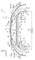
- FIG. 5 is a plan sectional view (a sectional view taken along line 1-1 in FIG. 3) showing a vehicle left side portion of a front bumper to which a vehicle bumper structure including a pedestrian collision detection sensor according to the present embodiment is applied. It is a top view which shows the whole front bumper shown by FIG.
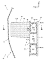
- FIG. 3 is a side sectional view of the front bumper shown in FIG. 2 as viewed from the left side of the vehicle (an enlarged sectional view taken along line 3-3 in FIG. 2).
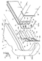
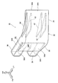
- FIG. 2 is an exploded perspective view of a state in which a vehicle left side portion of the front bumper shown in FIG. It is the perspective view seen from the vehicle left diagonal front which expands and shows the supporting member shown by FIG. FIG.
- FIG. 3 is a perspective view of the pressure sensor on the right side of the vehicle shown in FIG. It is a top view which shows typically the absorber in the modification 1 of this Embodiment. It is explanatory drawing for demonstrating a deformation
- an arrow FR appropriately shown in the drawings indicates the vehicle front side (vehicle longitudinal direction outer side), an arrow LH indicates the vehicle left side (one side in the vehicle width direction), and an arrow UP indicates the vehicle upper side.
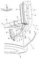
- the front bumper 12 is arranged at the front end of the vehicle (automobile) 10 and detects the collision (presence / absence) of the collision object to the vehicle 10.
- the front bumper 12 includes a bumper cover 14 that forms the front end of the vehicle 10, and a bumper reinforcement 20 that forms a bumper skeleton member (hereinafter referred to as “bumper RF 20”).
- the front bumper 12 includes a pair of left and right support members 30 disposed on both sides of the bumper RF20 in the vehicle width direction, and an absorber 50 disposed between the bumper cover 14 and the bumper RF20.
- the front bumper 12 includes a pedestrian collision detection sensor 70 for detecting a collision of the colliding body with the vehicle 10.
- each said structure is demonstrated.
- the bumper cover 14 is made of resin.
- the bumper cover 14 extends in the vehicle width direction and is fixedly supported to the vehicle body at a portion not shown. Further, both side portions 14 ⁇ / b> A of the bumper cover 14 in the vehicle width direction are inclined toward the vehicle rear side toward the outside in the vehicle width direction in a plan view, and constitute a corner portion 10 ⁇ / b> A of the vehicle 10.
- the inclination angle ⁇ with respect to the vehicle width direction of the vehicle width direction side portions 14A of the bumper cover 14 in the plan view is set to be relatively large.
- the bumper RF 20 is formed in a hollow, substantially rectangular column shape, and is disposed on the rear side of the bumper cover 14 (that is, on the inner side in the vehicle front-rear direction) with the vehicle width direction as the longitudinal direction.
- the bumper RF20 is made of a metal material such as aluminum and is manufactured by a technique such as extrusion.
- the positions of both ends in the vehicle width direction of the bumper RF20 in the vehicle width direction substantially coincide with the positions of the base ends of both side portions 14A in the vehicle width direction of the bumper cover 14. In other words, the bumper RF 20 is not disposed on the vehicle rear side with respect to the vehicle width direction both side portions 14A of the bumper cover 14 (the corner portion 10A of the vehicle 10).
- a plate-like reinforcing rib 26 is provided inside the bumper RF 20, and the reinforcing rib 26 is arranged with the vehicle vertical direction as the plate thickness direction, and the front wall 22 of the bumper RF 20. And the rear wall 24 are connected.
- the bumper RF20 has a cross-sectional structure in which a plurality (three in this embodiment) of substantially rectangular closed cross-sections are arranged in the vehicle vertical direction. That is, in the present embodiment, a pair of reinforcing ribs 26 are arranged inside the bumper RF20 in the vehicle vertical direction.
- the closed cross section disposed at the upper part of the bumper RF20 is the upper closed cross section 28A
- the closed cross section disposed at the intermediate portion in the vertical direction of the bumper RF20 is the intermediate closed cross section 28B
- the closed cross section disposed at the lower part of the bumper RF20 is a lower closed cross section 28C.
- a pair of left and right front side members 90 constituting a skeleton member on the vehicle body side are extended in the vehicle front-rear direction on the vehicle rear side of the bumper RF20.
- the both ends of the bumper RF 20 in the vehicle width direction are connected to the front end of the front side member 90 via a crash box 92.
- both ends in the vehicle width direction of the bumper RF20 are slightly projected outward in the vehicle width direction with respect to the crash box 92 and the front side member 90.
- the support member 30 is made of resin. Further, the support members 30 are provided at both ends in the vehicle width direction of the bumper RF20, and protrude from the both ends in the vehicle width direction of the bumper RF20 to the outside in the vehicle width direction. That is, the support members 30 are respectively arranged on the vehicle rear side with respect to the vehicle width direction both side portions 14A of the bumper cover 14 (the corner portion 10A of the vehicle 10). And since a pair of support member 30 is comprised symmetrically, in the following description, the support member 30 arrange
- the support member 30 is a body portion 32 and a pair of upper and lower fitting cylinder portions 38 (elements grasped as “fitting portions” in a broad sense). ) And reinforcing ribs 42 as a plurality of (four in this embodiment) “ribs”.
- the main body portion 32 is formed in a substantially V-shaped plate shape that is open to the rear side of the vehicle and the inner side in the vehicle width direction in plan view.
- the main body 32 includes an inclined wall 34 that is inclined toward the rear side of the vehicle in the plan view and a front wall 36 that extends inward in the vehicle width direction from the front end of the inclined wall 34. It is configured to include.
- the vehicle width direction inner side part of the front wall 36 of the main-body part 32 is arrange
- the front surface of the front wall 36 is a curved surface 36A, and the curved surface 36A is curved (bulged) in a substantially arc shape that is convex toward the vehicle front side in plan view. Further, the outer end in the vehicle width direction of the curved surface 36 ⁇ / b> A is smoothly connected to the inclined surface 34 ⁇ / b> A constituting the front surface of the inclined wall 34.
- the inner end of the curved surface 36A in the vehicle width direction is formed so as to contact the front surface 20A of the bumper RF20 in plan view. That is, the thickness of the front wall 36 is set so as to decrease toward the inner side in the vehicle width direction, and no step is generated at the joint portion between the inner end in the vehicle width direction of the curved surface 36A and the front surface 20A of the bumper RF20.
- a curved surface 36A is formed.
- a continuous surface is formed by the front surface 20A of the bumper RF20, the curved surface 36A of the support member 30, and the inclined surface 34A of the support member 30 (see FIG. 1).
- the fitting tube portion 38 is formed in a substantially rectangular tube shape with the vehicle width direction as an axial direction, and protrudes inward in the vehicle width direction from the front portion of the inclined wall 34. And a pair of fitting cylinder part 38 is arrange
- the support member 30 is formed with a slit 40 that is open inward in the vehicle width direction in a plan view between the front wall 38A of the fitting cylinder portion 38 and the front wall 36 of the main body portion 32.
- the reinforcing ribs 42 are paired in the vehicle vertical direction, and a pair of reinforcing ribs 42 are provided for the fitting cylinder portion 38, respectively.
- the reinforcing rib 42 is formed in a substantially triangular plate shape, and is arranged with the vehicle vertical direction as the plate thickness direction.
- the reinforcing rib 42 protrudes from the vehicle width direction outer side portion of the rear wall 38B of the fitting cylinder portion 38 toward the vehicle rear side, and is coupled to the rear surface of the inclined wall 34.
- the fitting cylinder part 38 and the inclined wall 34 are connected by the reinforcement rib 42, and it is comprised so that the bending rigidity to the vehicle rear side in the main-body part 32 of the supporting member 30 may become high.
- the absorber 50 is made of a foamed resin material, that is, urethane foam.
- the absorber 50 is provided between the bumper cover 14 and the bumper RF20, is formed in a long shape with the vehicle width direction as a longitudinal direction, and is bent toward the vehicle rear side at both side portions in the vehicle width direction.
- the absorber 50 includes an absorber main body portion 52 that constitutes an intermediate portion of the absorber 50 in the vehicle width direction, and an absorber side portion 54 that constitutes both side portions of the absorber 50 in the vehicle width direction.
- the absorber 50 is formed in a substantially rectangular shape in a cross-sectional view as viewed from the longitudinal direction.
- the absorber main body 52 is arranged adjacent to the front side of the vehicle at the upper part of the bumper RF20 (specifically, the part constituting the upper closed section 28A), and is fixed to the front surface 20A of the bumper RF20.
- the length of the absorber body 52 in the longitudinal direction is set to be substantially the same as the length of the bumper RF 20 in the longitudinal direction, and the vehicle of the absorber body 52 in the vehicle width direction is set.
- the positions at both ends in the width direction substantially coincide with the positions at both ends in the vehicle width direction of the bumper RF20.
- the absorber side portion 54 protrudes outward in the vehicle width direction from the bumper RF20, and is formed so as to cover the upper portion of the support member 30 from the front side of the vehicle.
- the inclined portions 56 constituting the base end side portion of the absorber side portion 54 move from the both ends in the vehicle width direction of the absorber main body 52 toward the outside in the vehicle width direction along the main body portion 32 of the support member 30. It extends to the rear side of the vehicle.
- the inclined portion 56 is disposed adjacent to the vehicle front side of the curved surface 36A and the inclined surface 34A of the main body portion 32.
- the tip portion 58 (corresponding to “both ends in the vehicle width direction of the absorber” in the present invention) constituting the tip side portion of the absorber side portion 54 is the tip 30A of the support member 30 (specifically, the main body portion 32). It is disposed outside the rear end) in the vehicle width direction.
- the tip 58 is bent toward the vehicle rear side at a position substantially outside the tip 30A of the support member 30 in the vehicle width direction, and protrudes (overhangs) from the tip 30A of the support member 30 to the vehicle rear side.
- the protruding (overhang) portion is an absorber-side protruding portion 60, and the absorber-side protruding portion 60 extends in the vehicle front-rear direction.
- an angle R (see FIG. 1) is formed in the bent portion of the tip portion 58, and the tip portion 58 is configured to bend smoothly.
- the rear surface 50A of the absorber 50 is formed with a curved concave portion 62 at a portion facing the curved surface 36A of the support member 30, and the curved concave portion 62 is substantially arcuate so as to follow the curved surface 36A in plan view. Is formed.
- the hardness of the absorber side part 54 and the part adjacent to the absorber side part 54 in the absorber main-body part 52 is comprised compared with the hardness of another part (in FIG. 1, hardness of hardness is shown). The portion that is configured higher is shown with a higher dot density).
- the hard part in the absorber 50 is made into the hard part 64A, the part whose hardness is lower than the hard part 64A is made into the soft part 64B, and the foaming ratio in the hard part 64A is compared with the foaming ratio of the soft part 64B. Is set low.
- boundary surface 66 between the hard portion 64A and the soft portion 64B in the absorber 50 is set on the inner side in the vehicle width direction with respect to both ends in the vehicle width direction of the bumper RF20, and also in the vehicle width direction toward the vehicle front side in plan view. Inclined inward.
- the thickness dimension T1 of the absorber side part 54 (the dimension in the direction orthogonal to the direction in which the absorber side part 54 extends in plan view) is the thickness dimension T2 of the absorber body part 52. It is set smaller than (a dimension in a direction orthogonal to the direction in which the absorber main body 52 extends in a plan view (that is, the vehicle longitudinal direction)). That is, the thickness of the portion of the absorber 50 that is disposed adjacent to the support member 30 is set to be thinner than the thickness of the portion of the absorber 50 that is disposed adjacent to the bumper RF20.
- a holding groove 68 as a “holding portion” for holding a pressure tube 72 described later is formed on the rear surface 50 ⁇ / b> A of the absorber 50.
- the holding groove portion 68 is formed in a substantially C shape opened to the rear side of the vehicle in a side sectional view (specifically, a circular shape partially opened to the rear side of the vehicle) and penetrates in the longitudinal direction of the absorber 50. ing.
- the pedestrian collision detection sensor 70 has a pressure tube 72 formed in a long shape, and a pressure sensor as a “pressure detector” that outputs a signal corresponding to a pressure change in the pressure tube 72. 82.
- the pressure tube 72 is configured as a hollow structure having a substantially annular cross section.
- the outer diameter of the pressure tube 72 is set slightly smaller than the inner diameter of the holding groove 68 of the absorber 50, and the length of the pressure tube 72 in the longitudinal direction is the length of the absorber 50 in the longitudinal direction. It is set longer than The pressure tube 72 is assembled (fitted) in the holding groove 68 (see FIG. 3).
- the pressure tube 72 is arranged along the longitudinal direction of the absorber 50.
- positioned along the absorber main-body part 52 in the pressure tube 72 is made into the pressure tube main-body part 74, and the part arrange
- the portion of the pressure tube side portion 76 that is disposed on the outer side in the vehicle width direction from the tip 30A of the support member 30 is the tip portion 78 of the pressure tube side portion 76 ("both ends in the vehicle width direction of the pressure tube" of the present invention). It corresponds to).
- the distal end portion 78 of the pressure tube side portion 76 is smoothly bent toward the vehicle rear side along the absorber side portion 54 and protrudes (overhangs) from the distal end 30A of the support member 30 toward the vehicle rear side.
- the protruding portion (overhang) is a pressure tube side protruding portion 80, and the pressure tube side protruding portion 80 extends in the vehicle front-rear direction.
- the pressure tube side projecting portion 80 is more than the absorber side projecting portion 60 of the absorber 50. It extends to the rear side of the vehicle.
- the outer peripheral surface of the pressure tube 72 is in contact with the rear surface 50A of the absorber 50 in a cross-sectional view seen from the longitudinal direction of the absorber 50, or They are arranged with a slight gap (see FIG. 3).
- the pressure tube 72 is disposed adjacent to the front side of the vehicle on the front surface 20A of the bumper RF20, the curved surface 36A of the support member 30, and the inclined surface 34A of the support member 30. And when the load to the vehicle rear side acts on the absorber 50 and the absorber 50 presses the pressure tube 72, it is comprised so that the reaction force with respect to the pressure tube 72 may arise with bumper RF20 and the supporting member 30.
- the pressure sensors 82 are provided at both ends of the pressure tube 72 in the vehicle width direction. As shown in FIG. 6, the pressure sensor 82 is fastened to the fender bracket 86 by a fastening member such as a bolt (not shown) as a “vehicle body side member” disposed on the rear side of the bumper cover 14 (not shown in FIG. 6). It is fixed.
- the fender bracket 86 is made of metal and is fixed to a fender liner 96 that covers the front wheel 94 of the vehicle 10 from above the vehicle.
- the pressure sensor 82 is electrically connected to the ECU 84 (which is an element grasped as a “collision determination unit” in a broad sense). Then, as the pressure tube 72 is deformed, a signal corresponding to a pressure change in the pressure tube 72 is output from the pressure sensor 82 to the ECU 84.
- a collision speed sensor (not shown) is electrically connected to the ECU 84 described above, and the collision speed sensor outputs a signal corresponding to the collision speed with the collision body to the ECU 84.
- the ECU 84 calculates the collision load based on the output signal of the pressure sensor 82 described above, and calculates the collision speed based on the output signal of the collision speed sensor. Further, the ECU 84 obtains the effective mass of the collision object from the calculated collision load and collision speed, determines whether the effective mass exceeds a threshold value, and determines whether the collision object to the front bumper 12 is a pedestrian. It is determined whether the vehicle is a person other than a pedestrian (for example, a roadside marker, a road obstacle such as a post cone).
- the bumper cover 14 is deformed to the rear side of the vehicle and presses the absorber 50 when the vehicle 10 collides with the collision body. For this reason, the absorber 50 is crushed (compressed and deformed) in the vehicle longitudinal direction, and the pressure tube 72 is deformed (collapsed). Thereby, the pressure in the pressure tube 72 changes.
- the pressure sensor 82 outputs a signal corresponding to the pressure change of the pressure tube 72 to the ECU 84, and the ECU 84 calculates the collision load based on the output signal of the pressure sensor 82.
- the ECU 84 calculates the collision speed based on the output signal of the collision speed sensor. Then, the ECU 84 obtains the effective mass of the collision object from the calculated collision load and collision speed, determines whether the effective mass exceeds the threshold value, and determines whether the collision object to the front bumper 12 is a pedestrian. Determine whether or not.
- support members 30 configured separately from the bumper RF20 are respectively assembled to both ends of the bumper RF20 in the vehicle width direction, and the support members 30 are both ends of the bumper RF20 in the vehicle width direction in plan view. From the portion to the vehicle width direction outside and the vehicle rear side. The support member 30 is disposed adjacent to the vehicle rear side of the absorber side portion 54 of the absorber 50 and the pressure tube side portion 76 of the pressure tube 72.
- the absorber side portion 54 and the pressure tube side portion 76 are connected to the vehicle by the support member 30. Can be supported from the rear side.
- the bumper RF20 When the bumper RF20 is disposed on the vehicle rear side with respect to the corner portion 10A of the vehicle 10, it is necessary to extend the bumper RF20 outward in the vehicle width direction from the front side member 90.
- a portion extending outward in the vehicle width direction in the bumper RF 20 corresponds to an inclination angle ⁇ of both side portions 14 A in the vehicle width direction of the bumper cover 14. It is necessary to bend to the rear side of the vehicle.
- the bumper RF20 is formed by extrusion molding or the like. For this reason, when the portion of the bumper RF20 that extends outward in the vehicle width direction is bent toward the vehicle rear side, the bumper RF20 is bent after the bumper RF20 is extruded. And, in the bending process of the bumper RF20, there is a processing restriction that the bending process over a predetermined angle cannot be performed. For this reason, in the vehicle 10 in which the inclination angle ⁇ of the both sides 14A in the vehicle width direction of the bumper cover 14 is relatively large as in the present embodiment, the bumper RF 20 cannot be bent due to the above processing restrictions. As a result, the bumper RF20 cannot be disposed on the vehicle rear side with respect to the corner portion 10A of the vehicle 10.
- the support members 30 are provided on both sides of the bumper RF 20 in the vehicle width direction. For this reason, the absorber side portion 54 and the pressure tube side portion 76 can be supported from the vehicle rear side by the support member 30 on the vehicle rear side of the corner portion 10 ⁇ / b> A of the vehicle 10. Accordingly, a reaction force against the pressure tube 72 can be generated by the support member 30 when the corner portion 10A of the vehicle 10 collides with the collision body. As a result, a collision with a collision object can be detected at the corner portion 10A of the vehicle 10.
- distal end portion 58 of the absorber 50 and the distal end portion 78 of the pressure tube 72 are disposed on the outer side in the vehicle width direction with respect to the distal end 30A of the support member 30. For this reason, the detection range of the pedestrian collision detection sensor 70 in the vehicle width direction can be set large.
- the absorber side protrusion 60 and the pressure tube side protrusion 80 protrude toward the vehicle rear side with respect to the tip 30A of the support member 30, and extend in the vehicle front-rear direction. For this reason, when a collision body collides from the side of the vehicle 10 (the vehicle width direction outside), a load inward in the vehicle width direction is input to the absorber side protrusion 60 and the pressure tube side protrusion 80, and the absorber side protrusion The portion 60 and the pressure tube side protruding portion 80 are deformed inward in the vehicle width direction. Thereby, the collision body which collides from the side of the vehicle 10 can also be detected. Therefore, a collision with a bicycle that tends to collide mainly from the side of the vehicle 10 can be detected.
- the curved surface 36A of the support member 30 is curved in a substantially arc shape that is convex toward the front of the vehicle in plan view, and forms a continuous surface with the front surface 20A of the bumper RF20.
- the pressure tube 72 can be bent outward in the vehicle width direction and rearward of the vehicle while being curved along the curved surface 36A. That is, the pressure tube 72 can be smoothly bent at both ends of the bumper RF 20 in the vehicle width direction and disposed along the main body portion 32 of the support member 30. Thereby, it can suppress that the pressure change in the boundary part of the pressure tube main-body part 74 of the pressure tube 72 and the pressure tube side part 76 becomes large. As a result, variations in the pressure change of the pressure tube 72 in the vehicle width direction are suppressed, and the detection accuracy of the pedestrian collision detection sensor 70 in the vehicle width direction can be equalized.
- the curved surface 36A of the support member 30 is disposed on the vehicle front side at both ends in the vehicle width direction of the bumper RF20. For this reason, the vehicle width direction both ends of bumper RF20 can be covered from the vehicle front side by the curved surface 36A (support member 30). Thereby, for example, the pressure tube 72 can be protected by the support member 30 against burrs or the like generated at both ends of the bumper RF20 in the vehicle width direction. Thereby, the danger to the pressure tube 72 can be reduced.
- a reinforcing rib 42 is integrally formed on the support member 30, and the reinforcing rib 42 connects the fitting cylinder portion 38 and the inclined wall 34 with the vehicle vertical direction being the plate thickness direction. For this reason, the bending rigidity to the vehicle rear side of the support member 30 can be made high by the reinforcing rib 42. Thereby, the reaction force with respect to the pressure tube 72 can be favorably generated at the time of the collision between the vehicle 10 and the collision object.
- the absorber 50 and the pressure tube 72 are disposed adjacent to the front side of the vehicle in the upper part of the bumper RF 20 (specifically, the part constituting the upper closed section 28A).
- the pedestrian who falls on the hood of the vehicle 10 can be detected well. That is, when the vehicle 10 collides with the pedestrian, the leg of the pedestrian hits the bumper cover 14, so that the pedestrian tends to fall on the hood of the vehicle 10.
- the bumper cover 14 is deformed so as to fall down obliquely downward on the rear side of the vehicle, and the upper portion of the absorber 50 is mainly pressed by the bumper cover 14.
- the pedestrian who has fallen on the hood of the vehicle 10 can be satisfactorily detected by arranging the absorber 50 and the pressure tube 72 adjacent to the vehicle front side above the bumper RF20.
- the pressure sensor 82 is fastened and fixed to a metal fender bracket 86. For this reason, compared with the case where the pressure sensor 82 is fixed to the bumper cover 14, the reliability with respect to the pressure sensor 82 can be improved.
- the pressure sensor 82 is fixed to the metal fender bracket 86, for example, the mounting strength of the pressure sensor 82 is increased compared to the case where the pressure sensor 82 is temporarily fixed to the resin bumper cover 14. And vibrations input to the pressure sensor 82 can be reduced. Further, for example, even when a slight impact is applied to the bumper cover 14 when the vehicle 10 is not traveling, the impact can be suppressed from being directly input to the pressure sensor 82. Furthermore, since the fender bracket 86 is disposed on the vehicle rear side of the bumper cover 14, the pressure sensor 82 can be prevented from being wetted by rain water, snow, or the like. As described above, the reliability of the pressure sensor 82 can be improved as compared with the case where the pressure sensor 82 is fixed to the bumper cover 14.
- the thickness dimension T1 of the absorber side part 54 is set smaller than the thickness dimension T2 of the absorber main body part 52. For this reason, it is possible to easily generate a pressure change in the pressure tube 72 when the absorber side portion 54 presses the pressure tube side portion 76. Thereby, the pressure sensitivity of the pressure tube side part 76 in the pressure tube 72 can be increased. Therefore, the pressure sensitivity of the pedestrian collision detection sensor 70 in the corner portion 10A of the vehicle 10 can be increased.
- the absorber 50 is composed of a hard part 64A and a soft part 64B having different hardnesses
- the absorber side part 54 is composed of a hard part 64A.
- the pressure tube 72 can be favorably pressed toward the support member 30 by the absorber side portion 54 having a high hardness. Also in this case, the pressure change in the pressure tube 72 can be easily generated, so that the pressure sensitivity of the pressure tube side portion 76 in the pressure tube 72 can be increased.
- the expansion ratio of the hard part 64A is set smaller than that of the soft part 64B. Therefore, in the absorber 50, the hard part 64A and the soft part 64B having different altitudes can be easily formed. Further, by appropriately adjusting the expansion ratio of the hard portion 64A and the soft portion 64B, for example, the absorber 50 suitable for each vehicle can be easily manufactured.
- the hardness of the absorber side portion 54 (hard portion 64A) of the absorber 50 is set higher than that in the present embodiment.
- the expansion ratio of the hard portion 64A is set to 5 times.
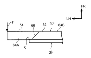
- the boundary surface 66 of the absorber 50 is set at a different position compared to the first modification. Specifically, as shown in FIG. 8A, the boundary surface 66 of the comparative example extends in the vehicle front-rear direction, and the position of the boundary surface 66 in the vehicle width direction is substantially the same as the position of both ends of the bumper RF20 in the vehicle width direction. I'm doing it. Then, by setting the hardness of the absorber side portion 54 as described above, when the load F to the rear side of the vehicle is input to the absorber side portion 54, the absorber side portion 54 and the support member 30 (FIG. 8A and FIG.
- 8B (not shown in the figure) can be configured to turn to the rear side of the vehicle with the vehicle width direction both ends of the bumper RF20 as the center C (see FIG. 8B). At this time, the absorber side portion 54 tends to bend starting from the rear end of the boundary surface 66.
- the absorber side part 54 and the support are supported in the same manner as described above.
- the member 30 (not shown in FIGS. 7A and 7B) tries to turn to the vehicle rear side with the vehicle width direction both ends of the bumper RF20 as the center C.
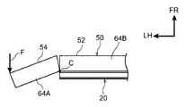
- the boundary surface 66 between the hard portion 64A and the soft portion 64B in the absorber 50 is inclined toward the vehicle front side as it goes in the vehicle width direction in a plan view, and more in the vehicle width direction than both ends in the vehicle width direction of the bumper RF20. Arranged inside.
- the boundary surface 66 is shifted inward in the vehicle width direction with respect to the center C that is the rotation center of the absorber side portion 54.
- the absorber 50 tends to bend from the boundary surface 66 shifted inward in the vehicle width direction from the center C.
- transforms the pressure tube 72 in the absorber 50 can be expanded in the longitudinal direction of the absorber 50.
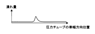
- FIG. 7C and FIG. 8C the amount of collapse of the pressure tube 72 is larger than that of the comparative example.
- the pressure tube 72 can be effectively deformed (collapsed) by the absorber 50.
- 7C and 8C show the collapse amount of the pressure tube 72 with respect to the vehicle width direction position of the pressure tube 72 when the pressure tube 72 is deformed.
- the position of the boundary surface of the absorber 50 is changed with respect to the first modification. That is, as shown in FIGS. 1 and 9A, the boundary surface 66A of Modification 2 is inclined inward in the vehicle width direction toward the vehicle front side in plan view, and the vehicle width of the bumper RF 20 in the vehicle front-rear direction. It is arranged so as to overlap with both ends in the direction. Specifically, the position of the rear end of the boundary surface 66A is disposed on the outer side in the vehicle width direction with respect to both ends in the vehicle width direction of the bumper RF20, and the position of the front end of the boundary surface 66A is with respect to both ends in the vehicle width direction of the bumper RF20.
- the hard portion 64A and the soft portion 64B are arranged in the vehicle front-rear direction at positions on the vehicle front side with respect to both ends of the bumper RF20 in the vehicle width direction.
- the pressure tube 72 can be effectively deformed (collapsed) by the absorber 50 at the time of collision with the collision body of the vehicle 10.
- the absorber 50 when the load F to the rear side of the vehicle is input to the absorber side portion 54, the absorber 50 is not supported by the support member 30 (not shown in FIGS. 9A and 9B) as in the first modification.
- the both ends of the bumper RF 20 in the vehicle width direction are set to the center C to rotate toward the rear side of the vehicle.
- the hard portion 64A disposed on the vehicle front side with respect to the boundary surface 66A may cause the soft portion 64B disposed on the vehicle rear side with respect to the boundary surface 66A to be crushed. it can.
- the part which deforms the pressure tube 72 in the absorber 50 can be expanded in the longitudinal direction of the absorber 50.
- FIG. 9C shows the amount of collapse of the pressure tube 72 with respect to the vehicle width direction position of the pressure tube 72 when the pressure tube 72 is deformed.
- Modification 3 in the present embodiment the position of the boundary surface of the absorber 50 is changed with respect to the first modification. That is, as shown in FIG. 1, the boundary surface 66B of Modification 3 extends outward in the vehicle width direction toward the vehicle front side in plan view, and overlaps with the tip 30A of the support member 30 in the vehicle width direction. Are arranged. That is, in Modification 3, at least the absorber-side protruding portion 60 is set as the hard portion 64A, and the other portion is set as the soft portion 64B. Further, the hard portion 64A and the soft portion 64B are arranged in the vehicle width direction at a position outside the vehicle width direction with respect to the tip 30A of the support member 30.
- the distal end portion 58 of the absorber side portion 54 is disposed on the outer side in the vehicle width direction with respect to the distal end 30A of the support member 30, but the distal end portion 58 may be omitted in the absorber side portion 54. That is, you may comprise so that the absorber side part 54 may not protrude outside the vehicle width direction rather than 30 A of front-end
- the absorber-side protruding portion 60 of the absorber side portion 54 protrudes (overhangs) from the front end 30 ⁇ / b> A of the support member 30 toward the vehicle rear side, but the absorber-side protruding portion in the absorber side portion 54. 60 may be omitted. That is, you may comprise so that the absorber side part 54 may not protrude (overhang) from the front-end
- the pressure tube 72 is held in the holding groove portion 68 of the absorber 50.
- the pressure tube 72 may be held by the bumper RF20 and the support member 30. That is, a holding groove for holding the pressure tube 72 may be formed in the bumper RF 20 and the support member 30.
- the absorber 50 has a hard portion 64A and a soft portion 64B having different hardnesses, and the absorber 50 is configured with two types of hardness.
- the type of hardness of the absorber 50 is changed as appropriate. May be.
- the hardness of the hard part 64A and the soft part 64B may be the same, and the absorber 50 may be configured with one kind of hardness.
- each of the absorber main body 52, the absorber side portion 54, and the absorber-side protruding portion 60 may be configured with different hardnesses, and the absorber 50 may be configured with three types of hardness.
- the entire absorber side portion 54 is composed of the hard portion 64A, but a part of the absorber side portion 54 may be composed of the hard portion 64A.
- the portion adjacent to the support member 30 of the absorber side portion 54 is configured by the soft portion 64B, and only the front portion of the absorber side portion 54 is configured by the hard portion 64A. May be.
- the pressure tube 72 can be deformed by transmitting a load to the rear side of the vehicle from the hard portion 64A to the soft portion 64B.
- the present invention is not limited to this, and for example, each of the above-described configurations
- the vehicle bumper structure S including the pedestrian collision detection sensor 70 may be applied to the rear bumper.
Landscapes
- Engineering & Computer Science (AREA)
- Mechanical Engineering (AREA)
- Body Structure For Vehicles (AREA)
- Force Measurement Appropriate To Specific Purposes (AREA)
Abstract
Description
図2に示されるように、バンパカバー14は樹脂製とされている。また、バンパカバー14は、車幅方向に延在されて、図示しない部分で車体に対し固定的に支持されている。さらに、バンパカバー14の車幅方向両側部分14Aは、平面視で車幅方向外側へ向かうに従い車両後側へ傾斜されて、車両10のコーナー部10Aを構成している。そして、本実施の形態における車両10では、平面視でバンパカバー14における車幅方向両側部分14Aの車幅方向に対する傾斜角度θが比較的大きく設定されている。
図2に示されるように、バンパRF20は、中空の略矩形柱状に形成されて、車幅方向を長手方向としてバンパカバー14の車両後側(すなわち車両前後方向内側)に配置されている。このバンパRF20は、アルミ系等の金属材料により構成され、押出成形等の手法によって製作されている。さらに、車幅方向におけるバンパRF20の車幅方向両端の位置がバンパカバー14の車幅方向両側部分14Aの基端の位置と略一致している。すなわち、バンパカバー14の車幅方向両側部分14A(車両10のコーナー部10A)に対して車両後側には、バンパRF20が配置されてない。
図2に示されるように、支持部材30は樹脂製とされている。また、支持部材30は、バンパRF20の車幅方向両端部にそれぞれ設けられて、バンパRF20の車幅方向両端部から車幅方向外側へ突出されている。すなわち、バンパカバー14の車幅方向両側部分14A(車両10のコーナー部10A)に対して車両後側に支持部材30がそれぞれ配置されている。そして、一対の支持部材30は、左右対称に構成されているため、以下の説明では、車両左側に配置された支持部材30について説明し、車両右側に配置された支持部材30についての説明は省略する。
図2に示されるように、アブソーバ50は、発泡樹脂材すなわちウレタンフォーム等によって構成されている。このアブソーバ50は、バンパカバー14とバンパRF20との間に設けられると共に、車幅方向を長手方向とした長尺状に形成され、車幅方向両側部分において車両後側へ屈曲されている。具体的には、アブソーバ50は、アブソーバ50の車幅方向中間部分を構成するアブソーバ本体部52と、アブソーバ50の車幅方向両側部分を構成するアブソーバサイド部54と、を含んで構成されている。また、図3に示されるように、アブソーバ50は、長手方向から見た断面視で略矩形状に形成されている。
図2に示されるように、歩行者衝突検知センサ70は、長尺状に形成された圧力チューブ72と、圧力チューブ72の圧力変化に応じた信号を出力する「圧力検出器」としての圧力センサ82と、を含んで構成されている。
変形例1では、本実施の形態と比べて、アブソーバ50のアブソーバサイド部54(硬質部64A)の硬度がさらに高く設定されている。例えば、硬質部64Aの発泡倍率が5倍に設定されている。これにより、車両10の衝突体との衝突時にアブソーバ50によって圧力チューブ72を効果的に変形させる(潰す)ことができる。
変形例2では、上記変形例1に対してアブソーバ50の境界面の位置が変更されている。すなわち、図1及び図9Aに示されるように、変形例2の境界面66Aが、平面視で、車両前側へ向かうに従い車幅方向内側へ傾斜されると共に、車両前後方向においてバンパRF20の車幅方向両端とオーバーラップして配置されている。詳しくは、境界面66Aの後端の位置がバンパRF20の車幅方向両端に対して車幅方向外側に配置されており、境界面66Aの前端の位置がバンパRF20の車幅方向両端に対して車幅方向内側に配置されている。このため、バンパRF20の車幅方向両端に対して車両前側の位置において、硬質部64Aと軟質部64Bとが車両前後方向に並ぶように配置される。これにより、変形例2においても車両10の衝突体との衝突時にアブソーバ50によって圧力チューブ72を効果的に変形させる(潰す)ことができる。
変形例3では、上記変形例1に対してアブソーバ50の境界面の位置が変更されている。つまり、図1に示されるように、変形例3の境界面66Bが、平面視で、車両前側へ向かうに従い車幅方向外側へ延びており、車幅方向において支持部材30の先端30Aとオーバーラップして配置されている。すなわち、変形例3では、少なくともアブソーバ側突出部60が硬質部64Aとして設定されており、その他の部分が軟質部64Bとして設定されている。また、支持部材30の先端30Aに対して車幅方向外側の位置で、硬質部64Aと軟質部64Bとが車幅方向に並ぶように配置されている。これにより、図示は省略するが、車両10の側方から衝突体が衝突した場合には、変形例2と同様に境界面66Bに対して車幅方向外側に配置された硬質部64Aによって軟質部64Bを押し潰すように作用させることができる。このため、変形例2と同様に、アブソーバ50において圧力チューブ72を変形させる部分をアブソーバ50の長手方向において拡大できる。これにより、圧力チューブ72の潰れ量が大きくなる。その結果、車両10の側方から衝突体が衝突したときに、アブソーバ50によって圧力チューブ72を効果的に変形させる(潰す)ことができる。
Claims (15)
- 車幅方向を長手方向として配置されたバンパリインフォースメントと、
車幅方向に延在され、前記バンパリインフォースメントの車両前後方向外側に隣接して配置されたアブソーバと、
前記バンパリインフォースメントと前記アブソーバとの間で車幅方向に延在された圧力チューブを含んで構成され、前記圧力チューブの圧力変化に応じた信号を出力する歩行者衝突検知センサと、
前記バンパリインフォースメントとは別体で構成され、平面視で前記バンパリインフォースメントの車幅方向両端部から車幅方向外側且つ車両前後方向内側へ延びると共に、前記アブソーバ及び前記圧力チューブの車両前後方向内側に隣接して配置された支持部材と、
を有する歩行者衝突検知センサを備えた車両用バンパ構造。 - 前記アブソーバの車幅方向両端部及び前記圧力チューブの車幅方向両端部が、前記支持部材の先端よりも車幅方向外側に配置された請求項1に記載の歩行者衝突検知センサを備えた車両用バンパ構造。
- 前記アブソーバには、前記圧力チューブを保持する保持部が形成されており、
前記アブソーバの前記車幅方向両端部には、前記支持部材の先端に対して車両前後方向内側へ突出され且つ車両前後方向に延びるアブソーバ側突出部が形成され、
前記圧力チューブの前記車幅方向両端部には、前記アブソーバ側突出部に沿って車両前後方向に延びる圧力チューブ側突出部が形成された請求項2に記載の歩行者衝突検知センサを備えた車両用バンパ構造。 - 前記支持部材は、前記バンパリインフォースメントの車幅方向両端部に対して車両前後方向外側に配置された湾曲面を有しており、
前記湾曲面が、平面視で前記バンパリインフォースメントの車両前後方向外側面と連続的な面を形成するように車両前後方向外側へ湾曲された請求項1~請求項3の何れか1項に記載の歩行者衝突検知センサを備えた車両用バンパ構造。 - 前記支持部材は樹脂製とされ、
前記支持部材には、車両上下方向を板厚方向としたリブが一体に形成された請求項1~請求項4の何れか1項に記載の歩行者衝突検知センサを備えた車両用バンパ構造。 - 前記バンパリインフォースメントは、車幅方向両側へ開放された閉断面構造に形成され、前記支持部材は、車幅方向内側へ突出された嵌合部を有しており、前記嵌合部が前記バンパリインフォースメントの閉断面内に嵌入されことで、前記支持部材が前記バンパリインフォースメントに組付けられる請求項1~請求項5の何れか1項に記載の車両用バンパ構造。
- 前記支持部材には、前記嵌合部と前記湾曲面との間の位置において、車幅方向内側へ開放されたスリットが形成されており、
前記支持部材が前記バンパリインフォースメントに組付けられた状態において、前記バンパリインフォースメントの前壁が前記スリットの内部に嵌め込まれている請求項6に記載の車両用バンパ構造。 - 前記アブソーバ及び前記圧力チューブが、前記バンパリインフォースメントの上部の車両前後方向外側に隣接して配置された請求項1~請求項7の何れか1項に記載の歩行者衝突検知センサを備えた車両用バンパ構造。
- 前記アブソーバの車両前後方向外側には、バンパカバーが設けられ、
前記歩行者衝突検知センサは、前記圧力チューブ内の圧力変化に応じた信号を出力する圧力検出器を有しており、
前記圧力検出器が、前記バンパカバーの車両前後方向内側に配置された金属製の車体側部材に固定された請求項1~請求項8の何れか1項に記載の歩行者衝突検知センサを備えた車両用バンパ構造。 - 前記アブソーバにおける前記支持部材と隣接して配置された部分の厚みが、前記アブソーバにおける前記バンパリインフォースメントと隣接して配置された部分の厚みに比して薄く設定された請求項1~請求項9の何れか1項に記載の歩行者衝突検知センサを備えた車両用バンパ構造。
- 少なくとも前記アブソーバにおける前記支持部材と隣接して配置された部分の硬度が、前記アブソーバにおける他の部分の硬度に比して高く設定された請求項1~請求項10の何れか1項に記載の歩行者衝突検知センサを備えた車両用バンパ構造。
- 前記アブソーバにおいて異なる硬度の境界面が、平面視で前記バンパリインフォースメントの車幅方向両端よりも車幅方向内側に配置され且つ車両前後方向外側へ向かうに従い車幅方向内側へ傾斜された請求項11に記載の歩行者衝突検知センサを備えた車両用バンパ構造。
- 前記アブソーバにおいて異なる硬度の境界面が、平面視で前記バンパリインフォースメントの車幅方向両端と車両前後方向にオーバーラップして配置され且つ車両前後方向外側へ向かうに従い車幅方向内側へ傾斜された請求項11に記載の歩行者衝突検知センサを備えた車両用バンパ構造。
- 少なくとも前記アブソーバ側突出部の硬度が、前記アブソーバにおける他の部位の硬度に比して高く設定され、
前記アブソーバにおいて異なる硬度の境界面が、平面視で前記支持部材の先端と車幅方向にオーバーラップして配置され且つ車両前後方向外側へ向かうに従い車幅方向外側へ傾斜された請求項3に記載の歩行者衝突検知センサを備えた車両用バンパ構造。 - 前記アブソーバが、発泡倍率の異なる発泡材により構成された請求項11~請求項14のいずれか1項に記載の歩行者衝突検知センサを備えた車両用バンパ構造。
Priority Applications (4)
| Application Number | Priority Date | Filing Date | Title |
|---|---|---|---|
| KR1020167021706A KR101854061B1 (ko) | 2014-02-10 | 2015-01-16 | 보행자 충돌 검지 센서를 구비한 차량용 범퍼 구조 |
| CN201580007859.8A CN106029450B (zh) | 2014-02-10 | 2015-01-16 | 具备行人碰撞检测传感器的车辆用保险杠结构 |
| EP15747047.7A EP3106354B1 (en) | 2014-02-10 | 2015-01-16 | Vehicle bumper structure equipped with pedestrian collision detection sensor |
| US15/117,271 US9944242B2 (en) | 2014-02-10 | 2015-01-16 | Vehicle bumper structure equipped with pedestrian collision detection sensor |
Applications Claiming Priority (2)
| Application Number | Priority Date | Filing Date | Title |
|---|---|---|---|
| JP2014023596A JP6090196B2 (ja) | 2014-02-10 | 2014-02-10 | 歩行者衝突検知センサを備えた車両用バンパ構造 |
| JP2014-023596 | 2014-02-10 |
Publications (1)
| Publication Number | Publication Date |
|---|---|
| WO2015118925A1 true WO2015118925A1 (ja) | 2015-08-13 |
Family
ID=53777733
Family Applications (1)
| Application Number | Title | Priority Date | Filing Date |
|---|---|---|---|
| PCT/JP2015/051135 WO2015118925A1 (ja) | 2014-02-10 | 2015-01-16 | 歩行者衝突検知センサを備えた車両用バンパ構造 |
Country Status (6)
| Country | Link |
|---|---|
| US (1) | US9944242B2 (ja) |
| EP (1) | EP3106354B1 (ja) |
| JP (1) | JP6090196B2 (ja) |
| KR (1) | KR101854061B1 (ja) |
| CN (1) | CN106029450B (ja) |
| WO (1) | WO2015118925A1 (ja) |
Cited By (2)
| Publication number | Priority date | Publication date | Assignee | Title |
|---|---|---|---|---|
| DE102015004420A1 (de) * | 2015-04-02 | 2016-10-06 | GM Global Technology Operations LLC (n. d. Ges. d. Staates Delaware) | Frontpartie für ein Kraftfahrzeug |
| WO2022079458A1 (ja) * | 2020-10-14 | 2022-04-21 | 日産自動車株式会社 | バンパレインフォースメント |
Families Citing this family (24)
| Publication number | Priority date | Publication date | Assignee | Title |
|---|---|---|---|---|
| JP6107747B2 (ja) * | 2014-06-02 | 2017-04-05 | トヨタ自動車株式会社 | 歩行者衝突検知センサを備えた車両前部構造 |
| JP6107784B2 (ja) | 2014-10-10 | 2017-04-05 | トヨタ自動車株式会社 | 歩行者衝突検知センサを備えた車両用バンパ構造 |
| JP6256427B2 (ja) | 2015-08-10 | 2018-01-10 | トヨタ自動車株式会社 | 歩行者衝突検知センサを備えた車両用バンパ構造 |
| JP6443686B2 (ja) * | 2015-09-03 | 2018-12-26 | 株式会社デンソー | 車両用衝突検知装置 |
| JP6555072B2 (ja) * | 2015-10-16 | 2019-08-07 | 株式会社デンソー | 保護制御装置 |
| DE102015117700A1 (de) * | 2015-10-16 | 2017-04-20 | Magna International Inc. | Querträger und Verfahren zur Herstellung eines Querträgers |
| US10266139B2 (en) * | 2016-11-02 | 2019-04-23 | Newtonoid Technologies, L.L.C. | Automotive transportation systems and methods for monitoring activity and providing controlled response |
| DE102016122288A1 (de) * | 2016-11-21 | 2018-05-24 | Dr. Ing. H.C. F. Porsche Aktiengesellschaft | Fahrzeugfrontstruktur |
| JP6704870B2 (ja) * | 2017-03-14 | 2020-06-03 | 豊田鉄工株式会社 | バンパリインフォースメント |
| US10099639B1 (en) | 2017-05-16 | 2018-10-16 | Ford Global Technologies, Llc | Energy absorbing device |
| JP6766776B2 (ja) * | 2017-08-21 | 2020-10-14 | トヨタ車体株式会社 | 車両用バンパー |
| JP6863209B2 (ja) * | 2017-09-29 | 2021-04-21 | トヨタ自動車株式会社 | センサ用プロテクタ及びこれを備えた車両 |
| CN111194282B (zh) * | 2017-10-24 | 2022-04-26 | 本田技研工业株式会社 | 碰撞检测构造 |
| WO2019082288A1 (ja) * | 2017-10-24 | 2019-05-02 | 本田技研工業株式会社 | 衝突検知構造 |
| US10521982B2 (en) * | 2018-01-17 | 2019-12-31 | GM Global Technology Operations LLC | Sensing tube diagnostic systems and methods |
| JP6962853B2 (ja) * | 2018-04-09 | 2021-11-05 | 本田技研工業株式会社 | 車両のリヤバンパ |
| DE102018206604B4 (de) * | 2018-04-27 | 2022-05-05 | Bayerische Motoren Werke Aktiengesellschaft | Stoßfängeranordnung |
| US10696253B2 (en) * | 2018-07-18 | 2020-06-30 | Public Transportation Safety Int'l | Vehicle frontal safety guard |
| JP7035938B2 (ja) * | 2018-09-27 | 2022-03-15 | トヨタ自動車株式会社 | センサ用プロテクタ |
| US11292412B2 (en) | 2019-02-15 | 2022-04-05 | Ford Global Technologies, Llc | Sealed bladder with pressure sensor |
| JP6677839B1 (ja) * | 2019-03-08 | 2020-04-08 | 株式会社神戸製鋼所 | 自動車のバンパー補強材 |
| US11097785B2 (en) * | 2019-07-19 | 2021-08-24 | Volvo Car Corporation | Automobile hood for decoupled pedestrian safety and durability |
| JP7182655B2 (ja) * | 2021-03-09 | 2022-12-02 | 本田技研工業株式会社 | 車両用センサの取付構造 |
| AU2022330833A1 (en) * | 2021-08-18 | 2024-03-14 | Public Transportation Safety Int'l Corp. | Vehicle safety guard system with impact detection |
Citations (5)
| Publication number | Priority date | Publication date | Assignee | Title |
|---|---|---|---|---|
| JP2006125999A (ja) * | 2004-10-28 | 2006-05-18 | Denso Corp | 衝突検出センサ |
| JP2007216804A (ja) * | 2006-02-15 | 2007-08-30 | Toyota Motor Corp | 車両用バンパ構造 |
| WO2011128971A1 (ja) * | 2010-04-13 | 2011-10-20 | トヨタ自動車株式会社 | 歩行者衝突検出装置 |
| JP2011245910A (ja) * | 2010-05-24 | 2011-12-08 | Toyota Motor Corp | 歩行者衝突検知装置 |
| JP2013023027A (ja) * | 2011-07-19 | 2013-02-04 | Denso Corp | 車両用衝突検知装置 |
Family Cites Families (11)
| Publication number | Priority date | Publication date | Assignee | Title |
|---|---|---|---|---|
| JP3235779B2 (ja) * | 1996-12-18 | 2001-12-04 | 株式会社椿本チエイン | 無人搬送車のバンパー取付構造 |
| DE19918202A1 (de) * | 1999-04-22 | 2000-10-26 | Bayer Ag | Sicherheitsstoßfänger |
| JP4325600B2 (ja) | 2005-09-06 | 2009-09-02 | トヨタ自動車株式会社 | 車両用フロントバンパ構造 |
| JP4726650B2 (ja) * | 2006-02-24 | 2011-07-20 | 本田技研工業株式会社 | 車両用センサモジュール |
| DE202011105867U1 (de) * | 2011-02-22 | 2011-10-24 | Continental Automotive Gmbh | Aufprallsensor mit einem elastisch deformierbaren Schlauch und zumindest einem Drucksensor |
| DE202011110919U1 (de) | 2011-02-22 | 2017-03-27 | Continental Automotive Gmbh | Aufprallsensor mit einem elastisch deformierbaren Schlauch und zumindest einem Drucksensor |
| DE202011050636U1 (de) * | 2011-07-06 | 2011-08-25 | Carolin Dörfler | Hilfsmittel zum Anzeichnen von Faschen |
| JP5983558B2 (ja) | 2013-07-31 | 2016-08-31 | トヨタ自動車株式会社 | 歩行者衝突検出装置を備えた車両用バンパ構造 |
| US8991903B1 (en) * | 2013-10-04 | 2015-03-31 | Ford Global Technologies, Llc | Deflector-catcher for small overlap vehicle impacts |
| JP5850018B2 (ja) * | 2013-10-21 | 2016-02-03 | トヨタ自動車株式会社 | 歩行者衝突検出センサの搭載構造 |
| JP6240486B2 (ja) * | 2013-11-26 | 2017-11-29 | 株式会社Subaru | 車両用衝突検知装置 |
-
2014
- 2014-02-10 JP JP2014023596A patent/JP6090196B2/ja active Active
-
2015
- 2015-01-16 US US15/117,271 patent/US9944242B2/en active Active
- 2015-01-16 KR KR1020167021706A patent/KR101854061B1/ko active IP Right Grant
- 2015-01-16 CN CN201580007859.8A patent/CN106029450B/zh active Active
- 2015-01-16 WO PCT/JP2015/051135 patent/WO2015118925A1/ja active Application Filing
- 2015-01-16 EP EP15747047.7A patent/EP3106354B1/en active Active
Patent Citations (5)
| Publication number | Priority date | Publication date | Assignee | Title |
|---|---|---|---|---|
| JP2006125999A (ja) * | 2004-10-28 | 2006-05-18 | Denso Corp | 衝突検出センサ |
| JP2007216804A (ja) * | 2006-02-15 | 2007-08-30 | Toyota Motor Corp | 車両用バンパ構造 |
| WO2011128971A1 (ja) * | 2010-04-13 | 2011-10-20 | トヨタ自動車株式会社 | 歩行者衝突検出装置 |
| JP2011245910A (ja) * | 2010-05-24 | 2011-12-08 | Toyota Motor Corp | 歩行者衝突検知装置 |
| JP2013023027A (ja) * | 2011-07-19 | 2013-02-04 | Denso Corp | 車両用衝突検知装置 |
Non-Patent Citations (1)
| Title |
|---|
| See also references of EP3106354A4 * |
Cited By (4)
| Publication number | Priority date | Publication date | Assignee | Title |
|---|---|---|---|---|
| DE102015004420A1 (de) * | 2015-04-02 | 2016-10-06 | GM Global Technology Operations LLC (n. d. Ges. d. Staates Delaware) | Frontpartie für ein Kraftfahrzeug |
| GB2537990A (en) * | 2015-04-02 | 2016-11-02 | Gm Global Tech Operations Llc | Front section for a motor vehicle |
| US9919669B2 (en) | 2015-04-02 | 2018-03-20 | GM Global Technology Operations LLC | Front section for a motor vehicle |
| WO2022079458A1 (ja) * | 2020-10-14 | 2022-04-21 | 日産自動車株式会社 | バンパレインフォースメント |
Also Published As
| Publication number | Publication date |
|---|---|
| EP3106354B1 (en) | 2018-06-13 |
| JP6090196B2 (ja) | 2017-03-08 |
| JP2015150906A (ja) | 2015-08-24 |
| EP3106354A1 (en) | 2016-12-21 |
| KR20160106713A (ko) | 2016-09-12 |
| US9944242B2 (en) | 2018-04-17 |
| US20160347270A1 (en) | 2016-12-01 |
| CN106029450A (zh) | 2016-10-12 |
| EP3106354A4 (en) | 2017-03-22 |
| CN106029450B (zh) | 2018-01-02 |
| KR101854061B1 (ko) | 2018-05-02 |
Similar Documents
| Publication | Publication Date | Title |
|---|---|---|
| JP6090196B2 (ja) | 歩行者衝突検知センサを備えた車両用バンパ構造 | |
| JP6256427B2 (ja) | 歩行者衝突検知センサを備えた車両用バンパ構造 | |
| JP6146383B2 (ja) | 圧力チューブ式歩行者衝突検知センサを備えた車両用バンパ構造 | |
| JP6107784B2 (ja) | 歩行者衝突検知センサを備えた車両用バンパ構造 | |
| JP6070647B2 (ja) | 歩行者衝突検知センサを備えた車両用バンパ構造 | |
| JP6332295B2 (ja) | 歩行者衝突検知センサを備えた車両前部構造 | |
| JP5494229B2 (ja) | 歩行者衝突検知装置 | |
| JP6149742B2 (ja) | 歩行者衝突検知センサを備えた車両用バンパ構造 | |
| JP6418074B2 (ja) | 歩行者衝突検知センサを備えた車両用バンパ構造 | |
| JP4434293B2 (ja) | 車両用衝突検知装置 | |
| JP6314714B2 (ja) | 歩行者衝突検知センサを備えた車両用バンパ構造 | |
| JP6028740B2 (ja) | 車両用バンパ構造 | |
| JP6447019B2 (ja) | 歩行者衝突検知センサを備えた車両用バンパ構造 | |
| WO2016136165A1 (ja) | 車両用衝突検知装置 | |
| JP6149758B2 (ja) | 歩行者衝突検知システム | |
| JP6032251B2 (ja) | 歩行者衝突検知センサを備えた車両用バンパ構造 | |
| JP5056495B2 (ja) | 車両用衝突検知装置 | |
| JP6565653B2 (ja) | 車両用衝突対象保護装置 | |
| WO2016092793A1 (ja) | 車両用衝突検知装置 | |
| JP5994666B2 (ja) | 歩行者衝突検出装置を備えた車両用バンパ | |
| JP6256358B2 (ja) | 歩行者衝突検知センサを備えた車両用バンパ構造 | |
| JP6443686B2 (ja) | 車両用衝突検知装置 | |
| US20230096952A1 (en) | Collision detection apparatus | |
| JP2015217799A (ja) | 歩行者衝突検出センサを備えた車両用バンパ構造 | |
| JP6334337B2 (ja) | 車両用衝突感知センサ取付構造 |
Legal Events
| Date | Code | Title | Description |
|---|---|---|---|
| 121 | Ep: the epo has been informed by wipo that ep was designated in this application |
Ref document number: 15747047 Country of ref document: EP Kind code of ref document: A1 |
|
| WWE | Wipo information: entry into national phase |
Ref document number: 15117271 Country of ref document: US |
|
| ENP | Entry into the national phase |
Ref document number: 20167021706 Country of ref document: KR Kind code of ref document: A |
|
| NENP | Non-entry into the national phase |
Ref country code: DE |
|
| REEP | Request for entry into the european phase |
Ref document number: 2015747047 Country of ref document: EP |
|
| WWE | Wipo information: entry into national phase |
Ref document number: 2015747047 Country of ref document: EP |