WO2015115217A1 - インホイールモータ駆動装置 - Google Patents
インホイールモータ駆動装置 Download PDFInfo
- Publication number
- WO2015115217A1 WO2015115217A1 PCT/JP2015/051167 JP2015051167W WO2015115217A1 WO 2015115217 A1 WO2015115217 A1 WO 2015115217A1 JP 2015051167 W JP2015051167 W JP 2015051167W WO 2015115217 A1 WO2015115217 A1 WO 2015115217A1
- Authority
- WO
- WIPO (PCT)
- Prior art keywords
- motor
- lubricating oil
- electric motor
- temperature sensor
- drive device
- Prior art date
Links
- 239000003921 oil Substances 0.000 claims abstract description 105
- 239000010687 lubricating oil Substances 0.000 claims abstract description 87
- 239000003638 chemical reducing agent Substances 0.000 claims abstract description 56
- 230000007246 mechanism Effects 0.000 claims abstract description 10
- 230000005856 abnormality Effects 0.000 abstract description 22
- 238000001514 detection method Methods 0.000 description 25
- 230000009467 reduction Effects 0.000 description 25
- XEEYBQQBJWHFJM-UHFFFAOYSA-N Iron Chemical compound [Fe] XEEYBQQBJWHFJM-UHFFFAOYSA-N 0.000 description 12
- 230000004044 response Effects 0.000 description 10
- 238000004891 communication Methods 0.000 description 8
- 230000002093 peripheral effect Effects 0.000 description 8
- RYGMFSIKBFXOCR-UHFFFAOYSA-N Copper Chemical compound [Cu] RYGMFSIKBFXOCR-UHFFFAOYSA-N 0.000 description 6
- 229910052802 copper Inorganic materials 0.000 description 6
- 239000010949 copper Substances 0.000 description 6
- 230000003111 delayed effect Effects 0.000 description 6
- 229910052742 iron Inorganic materials 0.000 description 6
- 238000004088 simulation Methods 0.000 description 6
- 230000002159 abnormal effect Effects 0.000 description 4
- 238000002474 experimental method Methods 0.000 description 4
- 238000005096 rolling process Methods 0.000 description 4
- 238000010586 diagram Methods 0.000 description 3
- 230000001050 lubricating effect Effects 0.000 description 3
- 230000003247 decreasing effect Effects 0.000 description 2
- 230000000694 effects Effects 0.000 description 2
- 239000012208 gear oil Substances 0.000 description 2
- 230000005484 gravity Effects 0.000 description 2
- 239000000314 lubricant Substances 0.000 description 2
- 238000005461 lubrication Methods 0.000 description 2
- 238000012986 modification Methods 0.000 description 2
- 230000004048 modification Effects 0.000 description 2
- 239000004065 semiconductor Substances 0.000 description 2
- 230000001133 acceleration Effects 0.000 description 1
- 238000009529 body temperature measurement Methods 0.000 description 1
- 230000008859 change Effects 0.000 description 1
- 238000001816 cooling Methods 0.000 description 1
- 238000007599 discharging Methods 0.000 description 1
- 238000009413 insulation Methods 0.000 description 1
- 238000000034 method Methods 0.000 description 1
- 230000010363 phase shift Effects 0.000 description 1
- 239000011347 resin Substances 0.000 description 1
- 229920005989 resin Polymers 0.000 description 1
- 239000000725 suspension Substances 0.000 description 1
- 230000001360 synchronised effect Effects 0.000 description 1
- 238000012360 testing method Methods 0.000 description 1
- 238000012546 transfer Methods 0.000 description 1
Images


Classifications
-
- B—PERFORMING OPERATIONS; TRANSPORTING
- B60—VEHICLES IN GENERAL
- B60L—PROPULSION OF ELECTRICALLY-PROPELLED VEHICLES; SUPPLYING ELECTRIC POWER FOR AUXILIARY EQUIPMENT OF ELECTRICALLY-PROPELLED VEHICLES; ELECTRODYNAMIC BRAKE SYSTEMS FOR VEHICLES IN GENERAL; MAGNETIC SUSPENSION OR LEVITATION FOR VEHICLES; MONITORING OPERATING VARIABLES OF ELECTRICALLY-PROPELLED VEHICLES; ELECTRIC SAFETY DEVICES FOR ELECTRICALLY-PROPELLED VEHICLES
- B60L3/00—Electric devices on electrically-propelled vehicles for safety purposes; Monitoring operating variables, e.g. speed, deceleration or energy consumption
- B60L3/0023—Detecting, eliminating, remedying or compensating for drive train abnormalities, e.g. failures within the drive train
- B60L3/0061—Detecting, eliminating, remedying or compensating for drive train abnormalities, e.g. failures within the drive train relating to electrical machines
-
- B—PERFORMING OPERATIONS; TRANSPORTING
- B60—VEHICLES IN GENERAL
- B60K—ARRANGEMENT OR MOUNTING OF PROPULSION UNITS OR OF TRANSMISSIONS IN VEHICLES; ARRANGEMENT OR MOUNTING OF PLURAL DIVERSE PRIME-MOVERS IN VEHICLES; AUXILIARY DRIVES FOR VEHICLES; INSTRUMENTATION OR DASHBOARDS FOR VEHICLES; ARRANGEMENTS IN CONNECTION WITH COOLING, AIR INTAKE, GAS EXHAUST OR FUEL SUPPLY OF PROPULSION UNITS IN VEHICLES
- B60K17/00—Arrangement or mounting of transmissions in vehicles
- B60K17/04—Arrangement or mounting of transmissions in vehicles characterised by arrangement, location or kind of gearing
- B60K17/043—Transmission unit disposed in on near the vehicle wheel, or between the differential gear unit and the wheel
-
- B—PERFORMING OPERATIONS; TRANSPORTING
- B60—VEHICLES IN GENERAL
- B60K—ARRANGEMENT OR MOUNTING OF PROPULSION UNITS OR OF TRANSMISSIONS IN VEHICLES; ARRANGEMENT OR MOUNTING OF PLURAL DIVERSE PRIME-MOVERS IN VEHICLES; AUXILIARY DRIVES FOR VEHICLES; INSTRUMENTATION OR DASHBOARDS FOR VEHICLES; ARRANGEMENTS IN CONNECTION WITH COOLING, AIR INTAKE, GAS EXHAUST OR FUEL SUPPLY OF PROPULSION UNITS IN VEHICLES
- B60K7/00—Disposition of motor in, or adjacent to, traction wheel
- B60K7/0007—Disposition of motor in, or adjacent to, traction wheel the motor being electric
-
- B—PERFORMING OPERATIONS; TRANSPORTING
- B60—VEHICLES IN GENERAL
- B60L—PROPULSION OF ELECTRICALLY-PROPELLED VEHICLES; SUPPLYING ELECTRIC POWER FOR AUXILIARY EQUIPMENT OF ELECTRICALLY-PROPELLED VEHICLES; ELECTRODYNAMIC BRAKE SYSTEMS FOR VEHICLES IN GENERAL; MAGNETIC SUSPENSION OR LEVITATION FOR VEHICLES; MONITORING OPERATING VARIABLES OF ELECTRICALLY-PROPELLED VEHICLES; ELECTRIC SAFETY DEVICES FOR ELECTRICALLY-PROPELLED VEHICLES
- B60L15/00—Methods, circuits, or devices for controlling the traction-motor speed of electrically-propelled vehicles
- B60L15/02—Methods, circuits, or devices for controlling the traction-motor speed of electrically-propelled vehicles characterised by the form of the current used in the control circuit
- B60L15/025—Methods, circuits, or devices for controlling the traction-motor speed of electrically-propelled vehicles characterised by the form of the current used in the control circuit using field orientation; Vector control; Direct Torque Control [DTC]
-
- B—PERFORMING OPERATIONS; TRANSPORTING
- B60—VEHICLES IN GENERAL
- B60L—PROPULSION OF ELECTRICALLY-PROPELLED VEHICLES; SUPPLYING ELECTRIC POWER FOR AUXILIARY EQUIPMENT OF ELECTRICALLY-PROPELLED VEHICLES; ELECTRODYNAMIC BRAKE SYSTEMS FOR VEHICLES IN GENERAL; MAGNETIC SUSPENSION OR LEVITATION FOR VEHICLES; MONITORING OPERATING VARIABLES OF ELECTRICALLY-PROPELLED VEHICLES; ELECTRIC SAFETY DEVICES FOR ELECTRICALLY-PROPELLED VEHICLES
- B60L15/00—Methods, circuits, or devices for controlling the traction-motor speed of electrically-propelled vehicles
- B60L15/20—Methods, circuits, or devices for controlling the traction-motor speed of electrically-propelled vehicles for control of the vehicle or its driving motor to achieve a desired performance, e.g. speed, torque, programmed variation of speed
- B60L15/2054—Methods, circuits, or devices for controlling the traction-motor speed of electrically-propelled vehicles for control of the vehicle or its driving motor to achieve a desired performance, e.g. speed, torque, programmed variation of speed by controlling transmissions or clutches
-
- B—PERFORMING OPERATIONS; TRANSPORTING
- B60—VEHICLES IN GENERAL
- B60L—PROPULSION OF ELECTRICALLY-PROPELLED VEHICLES; SUPPLYING ELECTRIC POWER FOR AUXILIARY EQUIPMENT OF ELECTRICALLY-PROPELLED VEHICLES; ELECTRODYNAMIC BRAKE SYSTEMS FOR VEHICLES IN GENERAL; MAGNETIC SUSPENSION OR LEVITATION FOR VEHICLES; MONITORING OPERATING VARIABLES OF ELECTRICALLY-PROPELLED VEHICLES; ELECTRIC SAFETY DEVICES FOR ELECTRICALLY-PROPELLED VEHICLES
- B60L3/00—Electric devices on electrically-propelled vehicles for safety purposes; Monitoring operating variables, e.g. speed, deceleration or energy consumption
- B60L3/04—Cutting off the power supply under fault conditions
-
- B—PERFORMING OPERATIONS; TRANSPORTING
- B60—VEHICLES IN GENERAL
- B60L—PROPULSION OF ELECTRICALLY-PROPELLED VEHICLES; SUPPLYING ELECTRIC POWER FOR AUXILIARY EQUIPMENT OF ELECTRICALLY-PROPELLED VEHICLES; ELECTRODYNAMIC BRAKE SYSTEMS FOR VEHICLES IN GENERAL; MAGNETIC SUSPENSION OR LEVITATION FOR VEHICLES; MONITORING OPERATING VARIABLES OF ELECTRICALLY-PROPELLED VEHICLES; ELECTRIC SAFETY DEVICES FOR ELECTRICALLY-PROPELLED VEHICLES
- B60L50/00—Electric propulsion with power supplied within the vehicle
- B60L50/50—Electric propulsion with power supplied within the vehicle using propulsion power supplied by batteries or fuel cells
- B60L50/51—Electric propulsion with power supplied within the vehicle using propulsion power supplied by batteries or fuel cells characterised by AC-motors
-
- H—ELECTRICITY
- H02—GENERATION; CONVERSION OR DISTRIBUTION OF ELECTRIC POWER
- H02K—DYNAMO-ELECTRIC MACHINES
- H02K11/00—Structural association of dynamo-electric machines with electric components or with devices for shielding, monitoring or protection
- H02K11/20—Structural association of dynamo-electric machines with electric components or with devices for shielding, monitoring or protection for measuring, monitoring, testing, protecting or switching
- H02K11/25—Devices for sensing temperature, or actuated thereby
-
- H—ELECTRICITY
- H02—GENERATION; CONVERSION OR DISTRIBUTION OF ELECTRIC POWER
- H02K—DYNAMO-ELECTRIC MACHINES
- H02K17/00—Asynchronous induction motors; Asynchronous induction generators
- H02K17/02—Asynchronous induction motors
- H02K17/12—Asynchronous induction motors for multi-phase current
-
- H—ELECTRICITY
- H02—GENERATION; CONVERSION OR DISTRIBUTION OF ELECTRIC POWER
- H02K—DYNAMO-ELECTRIC MACHINES
- H02K7/00—Arrangements for handling mechanical energy structurally associated with dynamo-electric machines, e.g. structural association with mechanical driving motors or auxiliary dynamo-electric machines
- H02K7/10—Structural association with clutches, brakes, gears, pulleys or mechanical starters
- H02K7/116—Structural association with clutches, brakes, gears, pulleys or mechanical starters with gears
-
- H—ELECTRICITY
- H02—GENERATION; CONVERSION OR DISTRIBUTION OF ELECTRIC POWER
- H02K—DYNAMO-ELECTRIC MACHINES
- H02K9/00—Arrangements for cooling or ventilating
- H02K9/19—Arrangements for cooling or ventilating for machines with closed casing and closed-circuit cooling using a liquid cooling medium, e.g. oil
-
- H—ELECTRICITY
- H02—GENERATION; CONVERSION OR DISTRIBUTION OF ELECTRIC POWER
- H02P—CONTROL OR REGULATION OF ELECTRIC MOTORS, ELECTRIC GENERATORS OR DYNAMO-ELECTRIC CONVERTERS; CONTROLLING TRANSFORMERS, REACTORS OR CHOKE COILS
- H02P29/00—Arrangements for regulating or controlling electric motors, appropriate for both AC and DC motors
- H02P29/60—Controlling or determining the temperature of the motor or of the drive
- H02P29/64—Controlling or determining the temperature of the winding
-
- H—ELECTRICITY
- H02—GENERATION; CONVERSION OR DISTRIBUTION OF ELECTRIC POWER
- H02P—CONTROL OR REGULATION OF ELECTRIC MOTORS, ELECTRIC GENERATORS OR DYNAMO-ELECTRIC CONVERTERS; CONTROLLING TRANSFORMERS, REACTORS OR CHOKE COILS
- H02P29/00—Arrangements for regulating or controlling electric motors, appropriate for both AC and DC motors
- H02P29/60—Controlling or determining the temperature of the motor or of the drive
- H02P29/68—Controlling or determining the temperature of the motor or of the drive based on the temperature of a drive component or a semiconductor component
-
- B—PERFORMING OPERATIONS; TRANSPORTING
- B60—VEHICLES IN GENERAL
- B60K—ARRANGEMENT OR MOUNTING OF PROPULSION UNITS OR OF TRANSMISSIONS IN VEHICLES; ARRANGEMENT OR MOUNTING OF PLURAL DIVERSE PRIME-MOVERS IN VEHICLES; AUXILIARY DRIVES FOR VEHICLES; INSTRUMENTATION OR DASHBOARDS FOR VEHICLES; ARRANGEMENTS IN CONNECTION WITH COOLING, AIR INTAKE, GAS EXHAUST OR FUEL SUPPLY OF PROPULSION UNITS IN VEHICLES
- B60K17/00—Arrangement or mounting of transmissions in vehicles
- B60K17/04—Arrangement or mounting of transmissions in vehicles characterised by arrangement, location or kind of gearing
- B60K17/043—Transmission unit disposed in on near the vehicle wheel, or between the differential gear unit and the wheel
- B60K17/046—Transmission unit disposed in on near the vehicle wheel, or between the differential gear unit and the wheel with planetary gearing having orbital motion
-
- B—PERFORMING OPERATIONS; TRANSPORTING
- B60—VEHICLES IN GENERAL
- B60K—ARRANGEMENT OR MOUNTING OF PROPULSION UNITS OR OF TRANSMISSIONS IN VEHICLES; ARRANGEMENT OR MOUNTING OF PLURAL DIVERSE PRIME-MOVERS IN VEHICLES; AUXILIARY DRIVES FOR VEHICLES; INSTRUMENTATION OR DASHBOARDS FOR VEHICLES; ARRANGEMENTS IN CONNECTION WITH COOLING, AIR INTAKE, GAS EXHAUST OR FUEL SUPPLY OF PROPULSION UNITS IN VEHICLES
- B60K7/00—Disposition of motor in, or adjacent to, traction wheel
- B60K2007/0038—Disposition of motor in, or adjacent to, traction wheel the motor moving together with the wheel axle
-
- B—PERFORMING OPERATIONS; TRANSPORTING
- B60—VEHICLES IN GENERAL
- B60K—ARRANGEMENT OR MOUNTING OF PROPULSION UNITS OR OF TRANSMISSIONS IN VEHICLES; ARRANGEMENT OR MOUNTING OF PLURAL DIVERSE PRIME-MOVERS IN VEHICLES; AUXILIARY DRIVES FOR VEHICLES; INSTRUMENTATION OR DASHBOARDS FOR VEHICLES; ARRANGEMENTS IN CONNECTION WITH COOLING, AIR INTAKE, GAS EXHAUST OR FUEL SUPPLY OF PROPULSION UNITS IN VEHICLES
- B60K7/00—Disposition of motor in, or adjacent to, traction wheel
- B60K2007/0092—Disposition of motor in, or adjacent to, traction wheel the motor axle being coaxial to the wheel axle
-
- B—PERFORMING OPERATIONS; TRANSPORTING
- B60—VEHICLES IN GENERAL
- B60L—PROPULSION OF ELECTRICALLY-PROPELLED VEHICLES; SUPPLYING ELECTRIC POWER FOR AUXILIARY EQUIPMENT OF ELECTRICALLY-PROPELLED VEHICLES; ELECTRODYNAMIC BRAKE SYSTEMS FOR VEHICLES IN GENERAL; MAGNETIC SUSPENSION OR LEVITATION FOR VEHICLES; MONITORING OPERATING VARIABLES OF ELECTRICALLY-PROPELLED VEHICLES; ELECTRIC SAFETY DEVICES FOR ELECTRICALLY-PROPELLED VEHICLES
- B60L2220/00—Electrical machine types; Structures or applications thereof
- B60L2220/10—Electrical machine types
- B60L2220/14—Synchronous machines
-
- B—PERFORMING OPERATIONS; TRANSPORTING
- B60—VEHICLES IN GENERAL
- B60L—PROPULSION OF ELECTRICALLY-PROPELLED VEHICLES; SUPPLYING ELECTRIC POWER FOR AUXILIARY EQUIPMENT OF ELECTRICALLY-PROPELLED VEHICLES; ELECTRODYNAMIC BRAKE SYSTEMS FOR VEHICLES IN GENERAL; MAGNETIC SUSPENSION OR LEVITATION FOR VEHICLES; MONITORING OPERATING VARIABLES OF ELECTRICALLY-PROPELLED VEHICLES; ELECTRIC SAFETY DEVICES FOR ELECTRICALLY-PROPELLED VEHICLES
- B60L2220/00—Electrical machine types; Structures or applications thereof
- B60L2220/40—Electrical machine applications
- B60L2220/44—Wheel Hub motors, i.e. integrated in the wheel hub
-
- B—PERFORMING OPERATIONS; TRANSPORTING
- B60—VEHICLES IN GENERAL
- B60L—PROPULSION OF ELECTRICALLY-PROPELLED VEHICLES; SUPPLYING ELECTRIC POWER FOR AUXILIARY EQUIPMENT OF ELECTRICALLY-PROPELLED VEHICLES; ELECTRODYNAMIC BRAKE SYSTEMS FOR VEHICLES IN GENERAL; MAGNETIC SUSPENSION OR LEVITATION FOR VEHICLES; MONITORING OPERATING VARIABLES OF ELECTRICALLY-PROPELLED VEHICLES; ELECTRIC SAFETY DEVICES FOR ELECTRICALLY-PROPELLED VEHICLES
- B60L2240/00—Control parameters of input or output; Target parameters
- B60L2240/10—Vehicle control parameters
- B60L2240/36—Temperature of vehicle components or parts
-
- B—PERFORMING OPERATIONS; TRANSPORTING
- B60—VEHICLES IN GENERAL
- B60L—PROPULSION OF ELECTRICALLY-PROPELLED VEHICLES; SUPPLYING ELECTRIC POWER FOR AUXILIARY EQUIPMENT OF ELECTRICALLY-PROPELLED VEHICLES; ELECTRODYNAMIC BRAKE SYSTEMS FOR VEHICLES IN GENERAL; MAGNETIC SUSPENSION OR LEVITATION FOR VEHICLES; MONITORING OPERATING VARIABLES OF ELECTRICALLY-PROPELLED VEHICLES; ELECTRIC SAFETY DEVICES FOR ELECTRICALLY-PROPELLED VEHICLES
- B60L2240/00—Control parameters of input or output; Target parameters
- B60L2240/40—Drive Train control parameters
- B60L2240/42—Drive Train control parameters related to electric machines
- B60L2240/421—Speed
-
- B—PERFORMING OPERATIONS; TRANSPORTING
- B60—VEHICLES IN GENERAL
- B60L—PROPULSION OF ELECTRICALLY-PROPELLED VEHICLES; SUPPLYING ELECTRIC POWER FOR AUXILIARY EQUIPMENT OF ELECTRICALLY-PROPELLED VEHICLES; ELECTRODYNAMIC BRAKE SYSTEMS FOR VEHICLES IN GENERAL; MAGNETIC SUSPENSION OR LEVITATION FOR VEHICLES; MONITORING OPERATING VARIABLES OF ELECTRICALLY-PROPELLED VEHICLES; ELECTRIC SAFETY DEVICES FOR ELECTRICALLY-PROPELLED VEHICLES
- B60L2240/00—Control parameters of input or output; Target parameters
- B60L2240/40—Drive Train control parameters
- B60L2240/42—Drive Train control parameters related to electric machines
- B60L2240/423—Torque
-
- B—PERFORMING OPERATIONS; TRANSPORTING
- B60—VEHICLES IN GENERAL
- B60L—PROPULSION OF ELECTRICALLY-PROPELLED VEHICLES; SUPPLYING ELECTRIC POWER FOR AUXILIARY EQUIPMENT OF ELECTRICALLY-PROPELLED VEHICLES; ELECTRODYNAMIC BRAKE SYSTEMS FOR VEHICLES IN GENERAL; MAGNETIC SUSPENSION OR LEVITATION FOR VEHICLES; MONITORING OPERATING VARIABLES OF ELECTRICALLY-PROPELLED VEHICLES; ELECTRIC SAFETY DEVICES FOR ELECTRICALLY-PROPELLED VEHICLES
- B60L2240/00—Control parameters of input or output; Target parameters
- B60L2240/40—Drive Train control parameters
- B60L2240/42—Drive Train control parameters related to electric machines
- B60L2240/425—Temperature
-
- B—PERFORMING OPERATIONS; TRANSPORTING
- B60—VEHICLES IN GENERAL
- B60L—PROPULSION OF ELECTRICALLY-PROPELLED VEHICLES; SUPPLYING ELECTRIC POWER FOR AUXILIARY EQUIPMENT OF ELECTRICALLY-PROPELLED VEHICLES; ELECTRODYNAMIC BRAKE SYSTEMS FOR VEHICLES IN GENERAL; MAGNETIC SUSPENSION OR LEVITATION FOR VEHICLES; MONITORING OPERATING VARIABLES OF ELECTRICALLY-PROPELLED VEHICLES; ELECTRIC SAFETY DEVICES FOR ELECTRICALLY-PROPELLED VEHICLES
- B60L2240/00—Control parameters of input or output; Target parameters
- B60L2240/40—Drive Train control parameters
- B60L2240/48—Drive Train control parameters related to transmissions
- B60L2240/486—Operating parameters
-
- B—PERFORMING OPERATIONS; TRANSPORTING
- B60—VEHICLES IN GENERAL
- B60L—PROPULSION OF ELECTRICALLY-PROPELLED VEHICLES; SUPPLYING ELECTRIC POWER FOR AUXILIARY EQUIPMENT OF ELECTRICALLY-PROPELLED VEHICLES; ELECTRODYNAMIC BRAKE SYSTEMS FOR VEHICLES IN GENERAL; MAGNETIC SUSPENSION OR LEVITATION FOR VEHICLES; MONITORING OPERATING VARIABLES OF ELECTRICALLY-PROPELLED VEHICLES; ELECTRIC SAFETY DEVICES FOR ELECTRICALLY-PROPELLED VEHICLES
- B60L2240/00—Control parameters of input or output; Target parameters
- B60L2240/40—Drive Train control parameters
- B60L2240/50—Drive Train control parameters related to clutches
- B60L2240/507—Operating parameters
-
- B—PERFORMING OPERATIONS; TRANSPORTING
- B60—VEHICLES IN GENERAL
- B60L—PROPULSION OF ELECTRICALLY-PROPELLED VEHICLES; SUPPLYING ELECTRIC POWER FOR AUXILIARY EQUIPMENT OF ELECTRICALLY-PROPELLED VEHICLES; ELECTRODYNAMIC BRAKE SYSTEMS FOR VEHICLES IN GENERAL; MAGNETIC SUSPENSION OR LEVITATION FOR VEHICLES; MONITORING OPERATING VARIABLES OF ELECTRICALLY-PROPELLED VEHICLES; ELECTRIC SAFETY DEVICES FOR ELECTRICALLY-PROPELLED VEHICLES
- B60L2250/00—Driver interactions
- B60L2250/16—Driver interactions by display
-
- H—ELECTRICITY
- H02—GENERATION; CONVERSION OR DISTRIBUTION OF ELECTRIC POWER
- H02K—DYNAMO-ELECTRIC MACHINES
- H02K5/00—Casings; Enclosures; Supports
- H02K5/04—Casings or enclosures characterised by the shape, form or construction thereof
- H02K5/15—Mounting arrangements for bearing-shields or end plates
-
- H—ELECTRICITY
- H02—GENERATION; CONVERSION OR DISTRIBUTION OF ELECTRIC POWER
- H02K—DYNAMO-ELECTRIC MACHINES
- H02K5/00—Casings; Enclosures; Supports
- H02K5/04—Casings or enclosures characterised by the shape, form or construction thereof
- H02K5/16—Means for supporting bearings, e.g. insulating supports or means for fitting bearings in the bearing-shields
- H02K5/173—Means for supporting bearings, e.g. insulating supports or means for fitting bearings in the bearing-shields using bearings with rolling contact, e.g. ball bearings
- H02K5/1732—Means for supporting bearings, e.g. insulating supports or means for fitting bearings in the bearing-shields using bearings with rolling contact, e.g. ball bearings radially supporting the rotary shaft at both ends of the rotor
-
- Y—GENERAL TAGGING OF NEW TECHNOLOGICAL DEVELOPMENTS; GENERAL TAGGING OF CROSS-SECTIONAL TECHNOLOGIES SPANNING OVER SEVERAL SECTIONS OF THE IPC; TECHNICAL SUBJECTS COVERED BY FORMER USPC CROSS-REFERENCE ART COLLECTIONS [XRACs] AND DIGESTS
- Y02—TECHNOLOGIES OR APPLICATIONS FOR MITIGATION OR ADAPTATION AGAINST CLIMATE CHANGE
- Y02T—CLIMATE CHANGE MITIGATION TECHNOLOGIES RELATED TO TRANSPORTATION
- Y02T10/00—Road transport of goods or passengers
- Y02T10/60—Other road transportation technologies with climate change mitigation effect
- Y02T10/64—Electric machine technologies in electromobility
-
- Y—GENERAL TAGGING OF NEW TECHNOLOGICAL DEVELOPMENTS; GENERAL TAGGING OF CROSS-SECTIONAL TECHNOLOGIES SPANNING OVER SEVERAL SECTIONS OF THE IPC; TECHNICAL SUBJECTS COVERED BY FORMER USPC CROSS-REFERENCE ART COLLECTIONS [XRACs] AND DIGESTS
- Y02—TECHNOLOGIES OR APPLICATIONS FOR MITIGATION OR ADAPTATION AGAINST CLIMATE CHANGE
- Y02T—CLIMATE CHANGE MITIGATION TECHNOLOGIES RELATED TO TRANSPORTATION
- Y02T10/00—Road transport of goods or passengers
- Y02T10/60—Other road transportation technologies with climate change mitigation effect
- Y02T10/70—Energy storage systems for electromobility, e.g. batteries
-
- Y—GENERAL TAGGING OF NEW TECHNOLOGICAL DEVELOPMENTS; GENERAL TAGGING OF CROSS-SECTIONAL TECHNOLOGIES SPANNING OVER SEVERAL SECTIONS OF THE IPC; TECHNICAL SUBJECTS COVERED BY FORMER USPC CROSS-REFERENCE ART COLLECTIONS [XRACs] AND DIGESTS
- Y02—TECHNOLOGIES OR APPLICATIONS FOR MITIGATION OR ADAPTATION AGAINST CLIMATE CHANGE
- Y02T—CLIMATE CHANGE MITIGATION TECHNOLOGIES RELATED TO TRANSPORTATION
- Y02T10/00—Road transport of goods or passengers
- Y02T10/60—Other road transportation technologies with climate change mitigation effect
- Y02T10/72—Electric energy management in electromobility
Definitions
- This invention relates to an in-wheel motor drive device, and relates to a technique for accurately detecting an abnormality of the in-wheel motor drive device using a coil temperature sensor and an oil temperature sensor.
- the in-wheel motor drive device has a speed reducer, a motor, and a wheel bearing.
- the loss of the in-wheel motor drive device is a loss obtained by adding the losses of the respective parts.
- the loss of the reducer is mainly due to the rolling resistance of the bearing part and the sliding resistance of the sliding part. The loss due to these resistances has a magnitude depending on the rotational speed if the bearing specifications and the clearance inside the reduction gear are defined (FIG. 7).
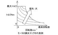
- ⁇ Motor loss is mostly iron loss, copper loss and mechanical loss.
- the magnitude of copper loss depends on the coil current
- the magnitude of iron loss depends on the coil current and the rotational speed
- the magnitude of mechanical loss depends on the rotational speed. Therefore, in the loss in the low speed and high torque region, the copper loss occupies most of the loss, and in the high speed and low torque region, the iron loss and the reduction gear loss occupy most of the loss (FIG. 8).
- the loss of the entire in-wheel motor drive device in the low-speed and high-torque region shown as region A is largely due to the copper loss of the motor. For this reason, in this region, the degree of increase in the coil temperature is larger than the degree of increase in the temperature of the lubricating oil, and the response of the lubricating oil temperature to the coil temperature is delayed.
- the iron loss and reduction gear loss of the motor account for most of the loss of the entire in-wheel motor drive device, so the increase in the lubricating oil temperature becomes the increase in the coil temperature. Bigger than that.
- the coil temperature sensor is placed between the slots of the stator, and it is difficult to apply the lubricating oil, and it is difficult to directly measure the temperature of the lubricating oil.
- the temperature of the coil and the stator is increased by the lubricating oil splashed on the coil and the stator core, and the coil temperature sensor responds to the coil temperature increased by the heat conduction and heat transfer. Response is greatly delayed.
- the detection target In order to detect an abnormality in the in-wheel motor drive unit, it is conceivable to set the detection target to temperature, and in particular, to detect the detection target to the temperature of the coil or lubricating oil.
- the coil temperature is arranged between the slots of the stator in order to avoid the influence of the lubricating oil, and the lubricating oil is hardly applied.
- the lubricant temperature detection sensor it is essential for the lubricant temperature detection sensor to be arranged at the most downstream side of the speed reducer in order to accurately detect the abnormality of the speed reducer, and it is difficult for this sensor to estimate the coil temperature of the motor.
- the motor coil temperature is detected, the differential value of the coil temperature change is calculated, and when this differential value exceeds a certain threshold, it is determined as abnormal.
- Output control is performed (Patent Document 1).
- the response of the output of the coil temperature measurement sensor is delayed with respect to the temperature rise of the lubricating oil, and it is difficult to accurately detect the abnormality of the in-wheel motor drive unit. Due to the response delay, the lubricating oil temperature rises. For example, when the heat resistance temperature of the resin member constituting the speed reducer is exceeded, the speed reducer may be abnormal.
- An object of the present invention is to provide an in-wheel motor drive device that can detect both the temperature of the lubricating oil and the temperature of the motor coil and accurately detect an abnormality in the entire output range of the motor. Is to provide a device.
- An in-wheel motor drive device is An electric motor 1 for driving the wheels; A wheel bearing 5 for rotating and supporting the wheel; A speed reducer 2 that decelerates the rotation of the electric motor 1 and transmits it to the wheel bearing 5; A lubricating oil supply mechanism Jk having a lubricating oil passage 29 provided at a lower portion of the speed reducer 2 and a supply oil passage 30 for supplying the lubricating oil from the lubricating oil passage 29 to the electric motor 1; An oil temperature sensor Sb that is provided in the lubricating oil passage 29 of the speed reducer 2 and detects the temperature of the lubricating oil in the lubricating oil passage; A coil temperature sensor Sa provided on the stator 9 of the electric motor 1 for detecting the temperature of the motor coil 78; The control device U1 for controlling the electric motor 1, when at least one of the temperature detected by the oil temperature sensor Sb and the temperature detected by the coil temperature sensor Sa exceeds a corresponding threshold value And a control device having motor output limiting means 95
- the “predetermined threshold value” is determined by, for example, experiments or simulations. Limiting the current of the electric motor includes setting the current of the electric motor to “zero”.
- the oil temperature sensor Sb provided in the lubricating oil passage 29 of the speed reducer 2 detects the temperature of the lubricating oil at all times (that is, every short time interval) or periodically.
- the coil temperature sensor Sa provided in the stator 9 detects the temperature of the motor coil 78 at all times (that is, every short time interval) or periodically.
- the motor output limiting means 95 of the control device U1 determines whether at least one of the temperature detected by the oil temperature sensor Sb and the coil temperature detected by the coil temperature sensor Sa has exceeded a corresponding first threshold value. Determine whether. When it is determined that the threshold value has been exceeded, the motor output limiting means 95 limits the current of the electric motor 1.
- the motor iron loss and reduction gear loss account for the majority of the overall loss of the in-wheel motor drive unit. For this reason, if only the coil temperature is detected by the coil temperature sensor Sa, the sensor output may cause a response delay with respect to the temperature increase of the lubricating oil that cools the speed reducer, and the speed reducer temperature may increase.
- the oil temperature sensor Sb detects the oil temperature and limits the current of the electric motor 1, thereby eliminating the detection delay of the increase in the lubricating oil temperature and preventing the speed reducer 2 from being abnormal. can do.
- the abnormality can be detected with high accuracy in the entire range from the low speed high torque region to the high speed low torque region in the output range of the electric motor 1.
- the corresponding threshold value of each of the oil temperature sensor Sb and the coil temperature sensor Sa includes a first threshold value and a second threshold value greater than the first threshold value
- the motor output limiting means 95 is configured to output the electric motor 1 when at least one of the temperature detected by the oil temperature sensor Sb and the temperature detected by the coil temperature sensor Sa exceeds the first threshold.
- the current of the electric motor 1 may be set to zero.
- the first and second threshold values are determined by, for example, experiments or simulations.
- the motor output limiting means 95 determines whether the oil temperature or the coil temperature is detected when at least one of the temperature detected by the oil temperature sensor Sb and the temperature detected by the coil temperature sensor Sa exceeds the first threshold value.
- the torque command value input to the electric motor 1 may be decreased at a fixed rate determined accordingly.
- the fixed ratio determined according to whether the oil temperature or the coil temperature is a fixed ratio (fixed value) determined according to whether the temperature exceeding the first threshold is the oil temperature or the coil temperature. That is, the fixed ratio varies depending on whether the oil temperature or the coil temperature.
- the predetermined ratio is appropriately determined by, for example, experimentation or simulation. Thus, by reducing the torque command value with a constant slope, it is possible to prevent the torque command value for the accelerator operation from changing sharply.
- the motor output limiting means 95 is configured to perform the first operation after at least one of the temperature detected by the oil temperature sensor Sb and the temperature detected by the coil temperature sensor Sa exceeds the first and second thresholds. When a certain time has elapsed from the time when the threshold value of 2 is exceeded, the output limit to the electric motor 1 may be released at that time. The predetermined time is determined by a test or simulation. By canceling the output restriction to the electric motor 1 under such conditions, that is, by inputting all the accelerator command values, it is possible to restore the motor torque and perform the operation according to the driver's will.
- the lubricating oil supply mechanism Jk includes a pump 28 that supplies the lubricating oil in the lubricating oil passage 29 to the electric motor 1 via the supply oil passage 30, and the pump 28 is connected to the electric motor 1. You may arrange
- the pump 28 may be provided outside an in-wheel motor drive unit including the electric motor 1, the wheel bearing 5, and the speed reducer 2.
- the lubricating oil tank in the apparatus main body can be omitted, and the oil passage to be provided in the apparatus main body can be reduced.
- the apparatus main body can be made compact. Therefore, the in-wheel motor drive device can be mounted on various vehicles, and versatility can be improved.
- the in-wheel motor drive device includes an electric motor 1 that drives wheels, a speed reducer 2 that decelerates the rotation of the electric motor 1, and an input shaft 3 (hereinafter, “ A wheel bearing 5 rotated by an output member 4 coaxial with the speed reducer input shaft 3), a lubricating oil supply mechanism Jk, and a control device U1 (FIG. 4).
- a reduction gear 2 is interposed between the wheel bearing 5 and the electric motor 1, a wheel hub as a driving wheel supported by the wheel bearing 5, a motor rotating shaft 6 of the electric motor 1, and a reduction gear input shaft 3.
- the output member 4 are connected on the same axis.
- a reduction gear housing 7 that houses the reduction gear 2 is connected to a suspension (not shown) of the vehicle.
- the side closer to the outer side in the vehicle width direction of the vehicle with the in-wheel motor drive device provided in the vehicle is referred to as the outboard side, and the side closer to the center of the vehicle is referred to as the inboard side. .
- the electric motor 1 is a radial gap type IPM motor (so-called embedded magnet type synchronous motor) in which a radial gap is provided between a motor stator 9 fixed to a motor housing 8 and a motor rotor 10 attached to the motor rotating shaft 6. .
- the motor housing 8 is provided with bearings 11 and 12 which are separated from each other in the axial direction, and the motor rotating shaft 6 is rotatably supported by the bearings 11 and 12.
- the motor rotating shaft 6 transmits the driving force of the electric motor 1 to the speed reducer 2.
- a flange portion 6 a extending radially outward is provided near the middle portion in the axial direction of the motor rotating shaft 6.
- a rotor fixing member 13 is provided on the flange portion 6 a, and the motor rotor 10 is attached to the rotor fixing member 13. Yes.
- the motor stator 9 of the electric motor 1 is provided with a coil temperature sensor Sa that detects the temperature of the motor coil 78.
- the coil temperature sensor Sa is a thermistor, for example. The temperature detected by the coil temperature sensor Sa is used to determine control for limiting the current of the electric motor 1 as will be described later.
- the speed reducer input shaft 3 has one axial end extending into the motor rotating shaft 6 and is splined to the motor rotating shaft 6.
- a bearing 14a is fitted in the cup portion 4a of the output member 4, and a bearing 14b is fitted in a cylindrical connecting member 26 connected to the cup portion 4a via an inner pin 22.
- the reduction gear input shaft 3 is rotatably supported by bearings 14a and 14b.
- Eccentric portions 15 and 16 are provided on the outer peripheral surface of the speed reducer input shaft 3 in the speed reducer housing 7. These eccentric portions 15 and 16 are provided with a 180 ° phase shift so that the centrifugal force due to the eccentric motion is canceled out from each other.
- the reducer 2 is a cycloid reducer having an outer pin housing Ih, a reducer input shaft 3, curved plates 17 and 18, a plurality of outer pins 19, inner pins 22, and a counterweight 21.
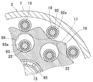
- 2 is a cross-sectional view of the speed reducer portion taken along the line II-II in FIG.
- two curved plates 17 and 18 formed with wavy trochoidal curves having a gentle outer shape are attached to the eccentric portions 15 and 16 via bearings 85, respectively.
- a plurality of outer pins 19 for guiding the eccentric movements of the curved plates 17 and 18 on the outer peripheral side are provided on the outer pin housing Ih (FIG. 1) inside the reducer housing 7.
- a plurality of inner pins 22 attached to the cup portion 4a (FIG. 1) are engaged with a plurality of circular through holes 89 provided in the curved plates 17 and 18 in an inserted state.
- needle roller bearings 92 and 93 are attached to each outer pin 19 and each inner pin 22.
- Each outer pin 19 is supported at both ends by needle roller bearings 92 and is in rolling contact with the outer peripheral surface of each curved plate 17, 18.
- the outer ring 93 a of the needle roller bearing 93 is in rolling contact with the inner periphery of each through-hole 89 of each curved plate 17, 18. Therefore, the contact resistance between the outer pin 19 and the outer periphery of each curved plate 17, 18 and the contact resistance between each inner pin 22 and the inner periphery of each through hole 89 are reduced.
- the eccentric motion of the curved plates 17 and 18 can be smoothly transmitted to the inner member 5a of the wheel bearing 5 as a rotational motion. That is, when the motor rotating shaft 6 rotates, the curved plates 17 and 18 provided on the speed reducer input shaft 3 rotating integrally with the motor rotating shaft 6 perform an eccentric motion. At this time, the outer pin 19 is engaged so as to be in rolling contact with the outer peripheral surfaces of the curved plates 17 and 18 that are eccentrically moved, and the curved plates 17 and 18 are connected to the inner pin 22 and the through hole 89 (FIG. 3). Due to the engagement, only the rotational motion of the curved plates 17 and 18 is transmitted to the output member 4 and the inner member 5a as rotational motion. The rotation of the inner member 5a is decelerated with respect to the rotation of the motor rotating shaft 6.
- the lubrication oil supply mechanism Jk is an axial oil supply mechanism that supplies lubricant oil used for both the lubrication of the speed reducer 2 and the cooling of the electric motor 1 from the inside of the motor rotating shaft 6.
- the lubricating oil supply mechanism Jk includes a lubricating oil passage 29, a supply oil passage 30, a discharge oil passage 38, and a pump 28.
- the lubricating oil passage 29 is configured in the speed reducer housing 7 in the speed reducer 2.
- the lubricating oil passage 29 includes a lubricating oil tank 29a.
- the lubricating oil tank 29 a is provided at the lower portion of the speed reducer housing 7, stores lubricating oil, and communicates with the lower portion of the motor housing 8.
- the supply oil passage 30 supplies lubricating oil to the electric motor 1 and the speed reducer 2 from the lubricating oil tank 29a.
- the supply oil passage 30 includes a suction-side oil passage 30a, a discharge-side oil passage 30b, a housing outer peripheral-side oil passage 30c, a communication passage 30d, a motor rotation shaft oil passage 30e, and a reduction gear oil passage 30f.
- the suction-side oil passage 30 a communicates with the suction port in the lubricating oil tank 29 a and the suction port of the pump 28, and includes a lower portion of the speed reducer housing 7 and a lower portion of the motor housing 8.
- the discharge-side oil passage 30 b communicates with the discharge port of the pump 28 and extends substantially radially outward in the motor housing 8.
- the housing outer peripheral side oil passage 30 c communicates with the discharge side oil passage 30 b and extends along the axial direction from the outboard side to the inboard side in the motor housing 8.
- the communication passage 30d is formed at the inboard side end of the motor housing 8, the inlet of the communication passage 30d communicates with the housing outer peripheral oil passage 30c, and the outlet of the communication passage 30d communicates with the motor rotating shaft oil passage 30e. Communicate.
- the motor rotation shaft oil passage 30e is provided along the axis in the motor rotation shaft 6. Part of the lubricating oil guided from the communication passage 30d to the motor rotation shaft oil passage 30e is formed inside the rotor fixing member 13 via a through hole extending radially outward of the motor rotation shaft 6 and the flange portion 6a.
- the motor rotor 10 is cooled by passing through the oil passage extending radially outward. Further, the coil 78 is cooled by injecting lubricating oil from the oil outlet of the oil passage to the inner peripheral surface of each coil end by the centrifugal force of the motor rotor 10 and the pressure of the pump 28.
- the speed reducer oil passage 30 f is provided in the speed reducer 2 and supplies lubricating oil to the speed reducer 2.
- the speed reducer oil passage 30 f includes an input shaft oil passage 36 and an oil supply port 37.
- the input shaft oil passage 36 communicates with the motor rotation shaft oil passage 30e and extends in the axial direction from the inboard side end inside the reduction gear input shaft 3 to the outboard side.
- the oil supply port 37 extends radially outward from the axial position where the eccentric portions 15 and 16 are provided in the input shaft oil passage 36.
- the reduction gear housing 7 is provided with a discharge oil passage 38 for discharging the lubricating oil used for lubricating the reduction gear 2 to the lubricating oil tank 29a.
- the pump 28 sucks up the lubricating oil stored in the lubricating oil tank 29a from the suction port in the lubricating oil tank 29a via the suction side oil passage 30a, and sequentially discharges the oil passage 30b and the housing outer periphery side oil passage 30c. Then, it is circulated through the communication passage 30d to the motor rotation shaft oil passage 30e and the reduction gear oil passage 30f.
- the pump 28 is disposed on the same axis between the electric motor 1 and the speed reducer 2.
- the pump 28 includes, for example, an unillustrated inner rotor that rotates as the output member 4 rotates, an outer rotor that rotates following the rotation of the inner rotor, a pump chamber, a suction port, and a discharge port (both shown in the figure). (Not shown).
- the outer rotor When the inner rotor is rotated by the rotation of the output member 4 driven by the electric motor 1, the outer rotor is driven to rotate. At this time, the inner rotor and the outer rotor rotate about different rotation axes, so that the volume of the pump chamber continuously changes. Thereby, the lubricating oil stored in the lubricating oil tank 29a is sucked up from the suction port via the suction side oil passage 30a and flows in from the suction port, and from the discharge port to the discharge side oil passage 30b, the housing outer peripheral side. The oil is sequentially sent to the oil passage 30c and the communication passage 30d.
- Lubricating oil is guided from the communication passage 30d to the motor rotation shaft oil passage 30e. Part of the lubricating oil cools the motor rotor 10 and the coil 78 as described above, and then moves below the motor housing 8 due to gravity and flows into the lubricating oil tank 29 a communicating with the lower portion of the motor housing 8.
- the lubricating oil introduced from the motor rotation shaft oil passage 30 e to the oil supply port 37 via the input shaft oil passage 36 is discharged from the outer diameter side opening end of the oil supply port 37. Since centrifugal force and the pressure of the pump 28 act on this lubricating oil, the lubricating oil moves radially outward in the speed reducer housing 7 while lubricating each part in the speed reducer 2. Thereafter, the lubricating oil moves downward by gravity and is stored in the lubricating oil tank 29a from the oil discharge port 38.
- the lubricating oil tank 29a is provided with an oil temperature sensor Sb that detects the temperature of the lubricating oil.
- the oil temperature sensor Sb is, for example, a thermistor. The temperature detected by the oil temperature sensor Sb is used for determination of control for limiting the current of the electric motor 1 as described later.
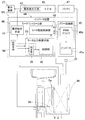
- FIG. 4 is a block diagram of a control system of the in-wheel motor drive device.
- the control device U1 includes an ECU 43 that is an electric control unit that controls the entire automobile, and an inverter device 44 that controls the electric motor 1 for traveling in accordance with a command from the ECU 43.
- the inverter device 44 includes a power circuit unit 45 provided for each electric motor 1 and a motor control unit 46 that controls the power circuit unit 45.
- the motor control unit 46 has a function of outputting information such as detection values and control values relating to the in-wheel motor drive device of the motor control unit 46 to the ECU 43.
- the power circuit unit 45 includes an inverter 45a that converts the DC power of the battery 47 into three-phase AC power that is used to drive the electric motor 1, and a PWM driver 45b that controls the inverter 45a.
- the inverter 45a is composed of a plurality of semiconductor switching elements (not shown), and the PWM driver 45b performs pulse width modulation on the input current command and gives an on / off command to each of the semiconductor switching elements.
- the motor control unit 46 includes a computer, a program executed on the computer, and an electronic circuit, and includes a motor drive control unit 48 as a basic control unit.
- the motor drive control unit 48 is a unit that converts the current command into a current command in accordance with an acceleration / deceleration command by a torque command or the like given from the ECU 43 that is a host control unit, and gives a current command to the PWM driver 45b.
- the motor drive control unit 48 obtains a motor current flowing from the inverter 45a to the electric motor 1 from the current detection means 35, and performs current feedback control.
- the motor drive control unit 48 obtains the rotation angle of the motor rotor of the electric motor 1 from the angle sensor 49 and performs vector control.
- the motor control unit 46 is provided with motor output limiting means 95, abnormality report means 41, and storage means 50.
- the motor output limiting means 95 is at least one of a temperature detected by the oil temperature sensor Sb (referred to as “oil temperature”) and a temperature of the motor coil (referred to as “coil temperature”) detected by the coil temperature sensor Sa. However, the current of the electric motor 1 is limited when a corresponding predetermined threshold value is exceeded.
- the motor output limiting unit 95 includes a determination unit 39 and a control unit 40.
- the determination unit 39 always determines whether the oil temperature and the coil temperature have exceeded the corresponding threshold values (that is, every short time interval).
- the threshold value of the oil temperature is determined based on, for example, the relationship between the oil temperature and the viscosity of the lubricating oil, the relationship between the viscosity of the lubricating oil and the rotational resistance of the electric motor 1 and the like by experiments and simulations.
- the threshold value of the coil temperature is determined as appropriate based on, for example, the relationship between the coil temperature and time that causes insulation in the motor coil, through experiments and simulations.
- each threshold value is stored in the storage means 50 so as to be rewritable. Further, in this embodiment, each threshold value for each detected temperature of the oil temperature sensor Sb and the coil temperature sensor Sa includes a first threshold value and a second threshold value that is larger than the first threshold value.
- control unit 40 passes the motor drive control unit 48 so as to reduce the current of the electric motor 1. To the power circuit unit 45.
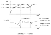
- FIG. 5 is a diagram showing the relationship between the coil temperature threshold and the motor input. Although not shown, the relationship between the oil temperature threshold and the motor input has the same relationship as in FIG. This will be described with reference to FIG. For example, it is assumed that the detection coil temperature exceeds the corresponding first threshold value among the detection coil temperature and the detection oil temperature.
- the control unit 40 starts limiting the output to the electric motor 1 when the detection coil temperature exceeds the first threshold value. Specifically, when the detection coil temperature exceeds the first threshold, the control unit 40 inputs torque to the electric motor 1 at a constant rate (a constant inclination) determined according to whether the oil temperature or the coil temperature.
- the power circuit unit 45 is commanded via the motor drive control unit 48 so as to decrease the command value.
- the control unit 40 instructs the power circuit unit 45 via the motor drive control unit 48 so that the current of the electric motor 1 becomes zero. If the detection coil temperature exceeds the first and second thresholds and then falls below the first threshold after a lapse of a certain time from the time when the detection coil temperature exceeds the second threshold, the electric motor at that time Release the output restriction to 1.
- the abnormality reporting unit 41 outputs abnormality occurrence information to the ECU 43 when the determination unit 39 determines that at least one of the detected oil temperature and the detected coil temperature has exceeded the corresponding first threshold value.
- the abnormality display means 42 provided in the ECU 43 receives the abnormality occurrence information output from the abnormality report means 41 and causes the display device 27 such as a console panel of the vehicle to perform a display notifying the abnormality.
- the determination unit 39 in the motor output limiting means 95 determines whether or not at least one of the detected oil temperature and coil temperature exceeds a corresponding predetermined threshold value. When it is determined that the threshold value has been exceeded, the control unit 40 commands the power circuit unit 45 via the motor drive control unit 48 so as to decrease the torque command value input to the electric motor 1.
- the motor iron loss and reduction gear loss account for the majority of the overall loss of the in-wheel motor drive unit. For this reason, if only the coil temperature is detected by the coil temperature sensor Sa, the sensor output may cause a response delay with respect to the temperature increase of the lubricating oil that cools the speed reducer, and the speed reducer temperature may increase.
- the oil temperature sensor Sb detects the oil temperature and limits the current of the electric motor 1, the detection delay of the rise in the lubricating oil temperature is eliminated, and the speed reducer 2 is abnormal. Can be prevented.
- the abnormality can be detected with high accuracy in the entire range from the low speed high torque region to the high speed low torque region in the output range of the electric motor 1.
- the motor output limiting means 95 starts limiting the output to the electric motor 1 when at least one of the detected oil temperature and coil temperature exceeds the corresponding first threshold, and the detected oil temperature and coil temperature. When at least one of these exceeds the corresponding second threshold, the current to the electric motor 1 is made zero. By thus limiting the output to the electric motor 1 in stages, the vehicle can be smoothly driven without causing the driver who performs the accelerator operation to feel uncomfortable.
- the motor output limiting means 95 is input to the electric motor 1 at a constant rate when at least one of the temperature detected by the oil temperature sensor Sb and the temperature detected by the coil temperature sensor Sa exceeds the first threshold value. By reducing the torque command value to be performed, it is possible to prevent the torque command value for the accelerator operation from changing sharply.
- a pump 28 is provided outside the in-wheel motor drive unit including the electric motor 1, the wheel bearing 5, and the speed reducer 2.
- the pump 28 is separated from the in-wheel motor drive unit. It may be driven by the drive source.
- the lubricating oil tank of the reduction gear housing 7 can be omitted, and the oil passage to be provided in the motor housing 8 can be reduced.
- the apparatus main body can be made compact. Therefore, the in-wheel motor drive device can be mounted on various vehicles, and versatility can be improved.
- the motor output limiting means may reduce the motor current to a predetermined ratio (for example, 90%) with respect to the current motor current when at least one detected temperature exceeds the corresponding first threshold value, Instead, it may be reduced to a predetermined value.
- a predetermined ratio for example, 90%
- the motor output limiting means reduces the motor current at a constant slope (a constant ratio) when at least one of the detected temperatures exceeds the corresponding first threshold, and when the detected temperature exceeds the second threshold,
- the motor current may be decreased with a steeper slope than the slope, that is, by increasing the ratio.
- the slope of the motor current may be a slope that draws a quadratic curve or the like instead of a straight line.
- the oil temperature sensor may be provided in a lubricating oil path other than the lubricating oil tank among the lubricating oil paths of the speed reducer.
- shaft parallel reduction gear, and other reduction gears are applicable.
Landscapes
- Engineering & Computer Science (AREA)
- Power Engineering (AREA)
- Transportation (AREA)
- Mechanical Engineering (AREA)
- Sustainable Development (AREA)
- Life Sciences & Earth Sciences (AREA)
- Sustainable Energy (AREA)
- Chemical & Material Sciences (AREA)
- Combustion & Propulsion (AREA)
- Microelectronics & Electronic Packaging (AREA)
- Arrangement Or Mounting Of Propulsion Units For Vehicles (AREA)
- Electric Propulsion And Braking For Vehicles (AREA)
- Control Of Ac Motors In General (AREA)
Abstract
潤滑油の温度とモータコイルの温度を検出することで、モータの出力範囲の全域で精度良く異常検知を行うことができるインホイールモータ駆動装置を提供する。このインホイールモータ駆動装置は、電動モータ(1)、車輪用軸受(5)、減速機(2)、潤滑油供給機構(Jk)および制御装置(U1)を備える。減速機(2)の潤滑油路(29)に、油温センサ(Sb)を設け、モータステータにコイル温度センサ(Sa)を設ける。制御装置(U1)は、油温センサ(Sb)で検出される温度、およびコイル温度センサ(Sa)で検出される温度の少なくとも一方が、対応する定められた閾値を超えたとき、電動モータ(1)の電流を制限するモータ出力制限手段(95)を有する。
Description
本出願は、2014年1月28日出願の特願2014-013290の優先権を主張するものであり、その全体を参照により本願の一部をなすものとして引用する。
この発明は、インホイールモータ駆動装置に関し、コイル温度センサと油温センサとを用いてインホイールモータ駆動装置の異常検知を精度良く行う技術に関する。
インホイールモータ駆動装置は、減速機、モータおよび車輪用軸受を有する。このインホイールモータ駆動装置の損失は、各部の損失が合算された損失となる。減速機の損失は、軸受部の転がり抵抗、摺動部の摺動抵抗が主な原因である。これら抵抗による損失は、軸受諸元や減速機内部の隙間が定められていれば、回転数に依存した大きさとなる(図7)。
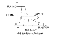
モータの損失は、鉄損、銅損および機械損が大部分を占める。銅損の大きさはコイル電流に依存し、鉄損の大きさはコイル電流と回転数に依存し、機械損の大きさは回転数に依存している。そのため、低速高トルク領域での損失は、銅損が損失の大部分を占め、高速低トルク領域では、鉄損および減速機損失が損失の大部分を占めることになる(図8)。
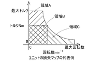
よって、インホイールモータ駆動装置ユニット全体におけるモータ回転数およびモータトルクに応じた損失マップには、図9に示すように、モータに起因した損失が占める領域Aと、モータと減速機の両方に起因する損失が占める領域Cとが存在する。領域Bは、減速機およびモータの損失が小さく、異常検知を行う必要のない領域である。
領域Aとして示す低速高トルク領域におけるインホイールモータ駆動装置全体の損失は、モータの銅損に大部分が起因する。このため、この領域では、コイル温度の上昇度合いが、潤滑油の温度上昇度合いに比べて大きく、潤滑油温は、コイル温度に対して応答遅れが生じる。一方で、領域Cとして示す高速低トルク領域では、モータの鉄損および減速機損失がインホイールモータ駆動装置全体の損失の大部分を占めるため、潤滑油温の上昇度合いがコイル温度の上昇度合いに比べて大きい。
コイル温度センサは、ステータのスロット間に配置され、潤滑油が掛かり難く、潤滑油の温度を直接測定することが難しい。コイルおよびステータコアに跳ね掛けられる潤滑油によってコイルおよびステータが温度上昇し、その熱伝導および熱伝達によって上昇したコイル温度にコイル温度センサが反応するため、コイル温度センサの出力は、潤滑油温に対して大きく応答が遅れる。
インホイールモータ駆動装置ユニットの異常検知のために、検出対象を温度にすることが考えられ、特に、検出対象をコイルや潤滑油の温度にすることが考えられる。コイル温度は、潤滑油の影響を避けるためにステータのスロット間に配置され、潤滑油は掛かり難い。また潤滑油温度の検出センサは、減速機の最下流に配置することが減速機の異常を精度良く検知するためには必須であり、このセンサはモータのコイル温度を推定することが難しい。
従来、インホイールモータ駆動装置の減速機について、潤滑経路の最下流に、潤滑油の温度センサを配置することが提案されている。油温センサのみでインホイールモータの出力領域全体の異常検知を行うと、低速高トルク領域において、コイル温度の上昇に対して潤滑油の温度の応答遅れが大きく、インホイールモータ駆動装置ユニットの異常検知を精密に行うことは難しい。応答遅れにより、コイル温度が上昇し続けてコイルの耐熱温度を超えた場合には、モータに過負荷が生じるおそれがある。
他の従来例では、インホイールモータ駆動装置のモータ部について、モータコイル温度を検出し、コイル温度変化の微分値を算出してこの微分値がある閾値を超えたときに、異常と判断して出力制御をしている(特許文献1)。コイル温度だけでは、高速低トルク領域において、コイル温度測定センサの出力が潤滑油の温度上昇に対して応答が遅れ、精度良くインホイールモータ駆動装置ユニットの異常検知を行うことが難しい。応答遅れにより、潤滑油温度が上昇し、例えば、減速機を構成する樹脂部材の耐熱温度を超えた場合には、減速機に異常が生じるおそれがある。
この発明の目的は、インホイールモータ駆動装置において、潤滑油の温度と、モータコイルの温度とを両方とも検出し、モータの出力範囲の全域で精度良く異常検知を行うことができるインホイールモータ駆動装置を提供することである。
以下、便宜上理解を容易にするために、実施形態の符号を参照して説明する。
この発明の一構成に係るインホイールモータ駆動装置は、
車輪を駆動する電動モータ1と、
前記車輪を回転支持する車輪用軸受5と、
前記電動モータ1の回転を減速して前記車輪用軸受5に伝達する減速機2と、
前記減速機2の下部に設けられた潤滑油路29、および前記潤滑油路29から前記電動モータ1に潤滑油を供給する供給油路30を有する潤滑油供給機構Jkと、
前記減速機2の潤滑油路29に設けられ、この潤滑油路の潤滑油の温度を検出する油温センサSbと、
前記電動モータ1のステータ9に設けられ、モータコイル78の温度を検出するコイル温度センサSaと、
前記電動モータ1を制御する制御装置U1であって、前記油温センサSbで検出される温度と前記コイル温度センサSaで検出される温度の少なくとも一方が、対応する定められた閾値を超えたとき、前記電動モータ1の電流を制限するモータ出力制限手段95を有する制御装置とを備える。
前記「定められた閾値」は、例えば、実験やシミュレーション等により定められる。
前記電動モータの電流を制限するとは、電動モータの電流を「零」にすることも含む。
前記電動モータの電流を制限するとは、電動モータの電流を「零」にすることも含む。
この構成によると、減速機2の潤滑油路29に設けた油温センサSbは、潤滑油の温度を常時に(すなわち、短い時間間隔ごとに)または定期的に検出する。ステータ9に設けたコイル温度センサSaは、モータコイル78の温度を常時(すなわち、短い時間間隔ごとに)にまたは定期的に検出する。制御装置U1のモータ出力制限手段95は、油温センサSbで検出される温度、およびコイル温度センサSaで検出されるコイル温度の少なくとも一方が、対応する定められた第1の閾値を超えたか否かを判定する。前記閾値を超えたとの判定で、モータ出力制限手段95は、電動モータ1の電流を制限する。
インホイールモータ駆動装置の損失による発熱は、低速高トルク領域においては、モータの銅損に大部分が起因する。このため、油温センサSbで潤滑油の温度を検出するだけでは、コイル温度の上昇に対して油温の応答が遅れることにより、コイル温度上昇の検出に遅れが生じる。これに対して、本構成では、コイル温度センサSaで検出したコイル温度を用いて電動モータ1の電流を制限するため、コイル温度の上昇の検出遅れをなくし、精密な異常検知を行うことができる。
高速低トルク領域においては、モータの鉄損および減速機損失がインホイールモータ駆動装置全体の損失の大部分を占める。このため、コイル温度センサSaでコイル温度を検出するだけでは、そのセンサ出力が、減速機を冷却する潤滑油の温度上昇に対して応答遅れを生じ、減速機温度が上昇するおそれがある。これに対して、本構成では、油温センサSbで油温を検出して電動モータ1の電流を制限するため、潤滑油温度上昇の検出遅れをなくし、減速機2に異常が生じることを防止することができる。
このように、即時に電動モータ1の電流を制限することにより、電動モータ1のコイル温度の上昇を抑えて電動モータ1に過負荷が生じることを防止できると共に、潤滑油の温度上昇を抑えて減速機2に異常が生じることを未然に防止することができる。したがって、電動モータ1の出力範囲のうち低速高トルク領域から高速低トルク領域にわたる全域で精度良く異常検知を行うことができる。
前記油温センサSbおよび前記コイル温度センサSaそれぞれの前記対応する閾値は、第1の閾値と、この第1の閾値よりも大きい第2の閾値とを含み、
前記モータ出力制限手段95は、前記油温センサSbで検出される温度と前記コイル温度センサSaで検出される温度の少なくとも一方が、前記第1の閾値を超えたとき、前記電動モータ1への出力制限を開始し、前記第2の閾値を超えたとき、前記電動モータ1の電流を零にしても良い。
前記モータ出力制限手段95は、前記油温センサSbで検出される温度と前記コイル温度センサSaで検出される温度の少なくとも一方が、前記第1の閾値を超えたとき、前記電動モータ1への出力制限を開始し、前記第2の閾値を超えたとき、前記電動モータ1の電流を零にしても良い。
前記第1,第2の閾値は、例えば、実験やシミュレーション等により定められる。
このように電動モータ1への出力制限を段階的に行うことで、アクセル操作を行う運転者に違和感を感じさせることなく、車両をスムースに走行させることができる。
このように電動モータ1への出力制限を段階的に行うことで、アクセル操作を行う運転者に違和感を感じさせることなく、車両をスムースに走行させることができる。
前記モータ出力制限手段95は、前記油温センサSbで検出される温度と前記コイル温度センサSaで検出される温度の少なくとも一方が、前記第1の閾値を超えたとき、油温かコイル温度かに応じて定められた一定の割合で前記電動モータ1に入力するトルク指令値を減少させても良い。
油温かコイル温度かに応じて定められた一定の割合とは、前記第1の閾値を超えた温度が油温かコイル温度かに応じて定められた一定の割合(固定値)である。すなわち、前記一定の割合は、油温かコイル温度かに応じて異なる。
前記定められた一定の割合は、例えば、実験やシミュレーション等により適宜に定められる。
このようにトルク指令値を一定の傾きで減少させることで、アクセル操作に対するトルク指令値が急峻に変化することを防ぐことができる。
油温かコイル温度かに応じて定められた一定の割合とは、前記第1の閾値を超えた温度が油温かコイル温度かに応じて定められた一定の割合(固定値)である。すなわち、前記一定の割合は、油温かコイル温度かに応じて異なる。
前記定められた一定の割合は、例えば、実験やシミュレーション等により適宜に定められる。
このようにトルク指令値を一定の傾きで減少させることで、アクセル操作に対するトルク指令値が急峻に変化することを防ぐことができる。
前記モータ出力制限手段95は、前記油温センサSbで検出される温度と前記コイル温度センサSaで検出される温度の少なくとも一方が、前記第1および前記第2の閾値を超えた後、前記第2の閾値を超えた時点から一定時間経過した後に第1の閾値を下回った場合、その時点で前記電動モータ1への出力制限を解除しても良い。前記一定時間は、試験やシミュレーションにより定められる。このような条件で電動モータ1への出力制限を解除する、つまりアクセル指令値を全て入力することで、モータトルクを復帰させて運転者の意に沿った運転を行うことができる。
前記潤滑油供給機構Jkは、前記供給油路30を経由して前記潤滑油路29の潤滑油を前記電動モータ1に供給するポンプ28を有し、当該前記ポンプ28が、前記電動モータ1と前記減速機2との間に同一軸心上に配置されても良い。
前記電動モータ1と前記車輪用軸受5と前記減速機2とを含むインホイールモータ駆動装置ユニットの外部に、前記ポンプ28が設けられても良い。この場合、例えば、装置本体内の潤滑油タンクを省略でき、また装置本体内に設けるべき油路の低減を図れる。これにより、装置本体のコンパクト化を図れる。したがって、インホイールモータ駆動装置を種々の車両に搭載でき汎用性を高めることができる。
請求の範囲および/または明細書および/または図面に開示された少なくとも2つの構成のどのような組合せも、本発明に含まれる。特に、請求の範囲の各請求項の2つ以上のどのような組合せも、本発明に含まれる。
この発明は、添付の図面を参考にした以下の好適な実施形態の説明から、より明瞭に理解されるであろう。しかしながら、実施形態および図面は単なる図示および説明のためのものであり、この発明の範囲を定めるために利用されるべきものではない。この発明の範囲は添付の請求の範囲によって定まる。添付図面において、複数の図面における同一の符号は、同一または相当する部分を示す。
この発明の第1の実施形態に係るインホイールモータ駆動装置の断面図である。
図1のII-II線断面となる減速機部分の断面図である。
図2の部分拡大図である。
図1のインホイールモータ駆動装置の制御系のブロック図である。
温度の閾値とモータ入力との関係を示す図である。
この発明の第2の実施形態に係るインホイールモータ駆動装置の断面図である。
減速機の損失マップの代表例を示す図である。
モータの損失マップの代表例を示す図である。
インホイールモータ駆動装置ユニットの損失マップの代表例を示す図である。
この発明の第1の実施形態に係るインホイールモータ駆動装置を図1ないし図5と共に説明する。図1に示すように、このインホイールモータ駆動装置は、車輪を駆動する電動モータ1と、この電動モータ1の回転を減速する減速機2と、この減速機2の入力軸3(以下、「減速機入力軸3」と称す)と同軸の出力部材4によって回転される車輪用軸受5と、潤滑油供給機構Jkと、制御装置U1(図4)とを有する。車輪用軸受5と電動モータ1との間に減速機2が介在し、車輪用軸受5で支持される駆動輪である車輪のハブと、電動モータ1のモータ回転軸6と減速機入力軸3と出力部材4とが同軸心上で連結されている。
減速機2を収納する減速機ハウジング7には、車両における図示外のサスペンションが連結される。なお、この明細書において、インホイールモータ駆動装置を車両に設けた状態で車両の車幅方向の外側寄りとなる側をアウトボード側と呼び、車両の中央寄りとなる側をインボード側と呼ぶ。
電動モータ1は、モータハウジング8に固定したモータステータ9と、モータ回転軸6に取り付けたモータロータ10との間にラジアルギャップを設けたラジアルギャップ型のIPMモータ(いわゆる埋込み磁石型同期モータ)である。モータハウジング8には、軸方向に離隔して軸受11,12が設けられ、これら軸受11,12に、モータ回転軸6が回転自在に支持されている。
モータ回転軸6は、電動モータ1の駆動力を減速機2に伝達するものである。モータ回転軸6の軸方向中間付近部には、径方向外方に延びるフランジ部6aが設けられ、このフランジ部6aにロータ固定部材13が設けられ、ロータ固定部材13にモータロータ10が取付けられている。
電動モータ1のモータステータ9には、モータコイル78の温度を検出するコイル温度センサSaが設けられている。コイル温度センサSaは、例えば、サーミスタである。このコイル温度センサSaで検出される温度は、後述するように、電動モータ1の電流を制限する制御の判断に用いられる。
減速機入力軸3は、軸方向一端がモータ回転軸6内に延びて、モータ回転軸6とスプライン嵌合されている。出力部材4のカップ部4a内に軸受14aが嵌合され、前記カップ部4aに内ピン22を介して連結される筒状の連結部材26内に軸受14bが嵌合されている。減速機入力軸3は、軸受14a,14bにより回転自在に支持されている。減速機ハウジング7内における、減速機入力軸3の外周面には、偏心部15,16が設けられる。これら偏心部15,16は、偏心運動による遠心力が互いに打ち消されるように180°位相をずらして設けられている。
減速機2は、外ピンハウジングIhと、減速機入力軸3と、曲線板17,18と、複数の外ピン19と、内ピン22と、カウンタウェイト21とを有するサイクロイド減速機である。
図2は、図1のII-II線断面となる減速機部分の断面図である。減速機2では、外形がなだらかな波状のトロコイド曲線で形成された2枚の曲線板17,18が、それぞれ軸受85を介して、各偏心部15,16に装着されている。これら各曲線板17,18の偏心運動を外周側で案内する複数の外ピン19が、それぞれ減速機ハウジング7の内側の外ピンハウジングIh(図1)に設けられる。カップ部4a(図1)に取り付けられた複数の内ピン22が、各曲線板17,18の内部に設けられた複数の円形の貫通孔89に挿入状態に係合されている。
図2は、図1のII-II線断面となる減速機部分の断面図である。減速機2では、外形がなだらかな波状のトロコイド曲線で形成された2枚の曲線板17,18が、それぞれ軸受85を介して、各偏心部15,16に装着されている。これら各曲線板17,18の偏心運動を外周側で案内する複数の外ピン19が、それぞれ減速機ハウジング7の内側の外ピンハウジングIh(図1)に設けられる。カップ部4a(図1)に取り付けられた複数の内ピン22が、各曲線板17,18の内部に設けられた複数の円形の貫通孔89に挿入状態に係合されている。
図3に拡大して示すように、各外ピン19と各内ピン22には針状ころ軸受92,93が装着される。各外ピン19は、それぞれ針状ころ軸受92で両端支持されて各曲線板17,18の外周面と転接する。また各内ピン22は、針状ころ軸受93の外輪93aが、それぞれ各曲線板17,18の各貫通孔89の内周に転接する。したがって、外ピン19と各曲線板17,18の外周との接触抵抗、および各内ピン22と各貫通孔89の内周との接触抵抗を低減する。
よって、図1に示すように、各曲線板17,18の偏心運動をスムーズに車輪用軸受5の内方部材5aに回転運動として伝達し得る。すなわちモータ回転軸6が回転すると、このモータ回転軸6と一体回転する減速機入力軸3に設けられた各曲線板17,18が偏心運動を行う。このとき外ピン19が偏心運動する各曲線板17,18の外周面と転がり接触するように係合すると共に、各曲線板17,18が、内ピン22と貫通孔89(図3)との係合によって、各曲線板17,18の自転運動のみが出力部材4および内方部材5aに回転運動として伝達される。モータ回転軸6の回転に対して内方部材5aの回転は減速されたものとなる。
潤滑油供給機構Jkは、減速機2の潤滑および電動モータ1の冷却の両方に用いられる潤滑油をモータ回転軸6の内部から供給する軸心給油機構である。この潤滑油供給機構Jkは、潤滑油路29と、供給油路30と、排出油路38と、ポンプ28とを有する。潤滑油路29は、減速機2における減速機ハウジング7内に構成される。この潤滑油路29は潤滑油タンク29aを含む。潤滑油タンク29aは、減速機ハウジング7の下部に設けられ潤滑油を貯留し、モータハウジング8の下部に連通する。
供給油路30は、潤滑油タンク29aから、電動モータ1および減速機2に潤滑油を供給する。この供給油路30は、吸込側油路30a、吐出側油路30b、ハウジング外周側油路30c、連通路30d、モータ回転軸油路30e、および減速機油路30fを含む。吸込側油路30aは、潤滑油タンク29a内の吸込口とポンプ28の吸入口とにわたって連通し、減速機ハウジング7の下部とモータハウジング8の下部とで構成される。吐出側油路30bは、ポンプ28の吐出口に連通し、モータハウジング8内における径方向外方に略沿って延びる。
ハウジング外周側油路30cは、吐出側油路30bに連通し、モータハウジング8内におけるアウトボード側からインボード側に軸方向に沿って延びる。連通路30dは、モータハウジング8のインボード側端に形成され、この連通路30dの流入口がハウジング外周側油路30cに連通し、この連通路30dの流出口がモータ回転軸油路30eに連通する。
モータ回転軸油路30eは、モータ回転軸6内の軸心に沿って設けられる。連通路30dからモータ回転軸油路30eに導かれた潤滑油の一部は、モータ回転軸6およびフランジ部6aの半径方向外方に延びる貫通孔を経由して、ロータ固定部材13内部に形成された半径方向外方に延びる油路を通ることで、モータロータ10が冷却される。さらに前記油路の油吹出し口から、各コイルエンドの内周面に対し、モータロータ10の遠心力とポンプ28の圧力とにより潤滑油を射出することで、コイル78が冷却される。
減速機油路30fは、減速機2に設けられ、潤滑油を減速機2に供給する。この減速機油路30fは、入力軸油路36と、オイル供給口37とを有する。入力軸油路36は、モータ回転軸油路30eに連通し、減速機入力軸3の内部におけるインボード側端からアウトボード側に軸方向に延びる。オイル供給口37は、入力軸油路36のうち偏心部15,16が設けられる軸方向位置から、半径方向外方に延びている。
減速機ハウジング7には、減速機2の潤滑に供された潤滑油を潤滑油タンク29aに排出する排出油路38が設けられている。
減速機ハウジング7には、減速機2の潤滑に供された潤滑油を潤滑油タンク29aに排出する排出油路38が設けられている。
ポンプ28は、潤滑油タンク29aに貯留された潤滑油を、潤滑油タンク29a内の吸込口から吸込側油路30aを経由させて吸い上げて順次、吐出側油路30b、ハウジング外周側油路30c、連通路30dを経由してモータ回転軸油路30eおよび減速機油路30fに循環させる。このポンプ28は、電動モータ1と減速機2との間に同一軸心上に配置される。ポンプ28は、例えば、出力部材4の回転により回転する図示外のインナーロータと、このインナーロータの回転に伴って従動回転するアウターロータと、ポンプ室と、吸入口と、吐出口(いずれも図示せず)とを有するサイクロイドポンプである。
電動モータ1に駆動される出力部材4の回転により前記インナーロータが回転すると、前記アウターロータは従動回転する。このときインナーロータおよびアウターロータがそれぞれ異なる回転軸心を中心として回転することで、前記ポンプ室の容積が連続的に変化する。これにより、潤滑油タンク29aに貯留された潤滑油は、吸込口から吸込側油路30aを経由して吸い上げられて前記吸入口から流入し、前記吐出口から吐出側油路30b、ハウジング外周側油路30c、連通路30dに順次圧送される。
潤滑油は、連通路30dからモータ回転軸油路30eに導かれる。潤滑油の一部は、前述のようにモータロータ10およびコイル78を冷却した後、重力によってモータハウジング8の下方に移動し、このモータハウジング8の下部に連通する潤滑油タンク29aに流れ込む。
モータ回転軸油路30eから入力軸油路36を経由してオイル供給口37に導かれた潤滑油は、このオイル供給口37の外径側開口端から排出される。この潤滑油には遠心力とポンプ28の圧力とが作用するため、潤滑油は減速機2内の各部を潤滑しながら減速機ハウジング7内で半径方向外方に移動する。その後、潤滑油は、重力によって下方に移動し、オイル排出口38から潤滑油タンク29aに貯留される。潤滑油タンク29aには、潤滑油の温度を検出する油温センサSbが設けられる。油温センサSbは、例えば、サーミスタである。この油温センサSbで検出される温度は、後述するように、電動モータ1の電流を制限する制御の判断に用いられる。
制御系について説明する。
図4は、このインホイールモータ駆動装置の制御系のブロック図である。
前記制御装置U1は、自動車全般の制御を行う電気制御ユニットであるECU43と、このECU43の指令に従って走行用の電動モータ1の制御を行うインバータ装置44とを有する。インバータ装置44は、各電動モータ1に対して設けられたパワー回路部45と、このパワー回路部45を制御するモータコントロール部46とを有する。モータコントロール部46は、このモータコントロール部46が持つインホイールモータ駆動装置に関する各検出値や制御値等の各情報をECU43に出力する機能を有する。
図4は、このインホイールモータ駆動装置の制御系のブロック図である。
前記制御装置U1は、自動車全般の制御を行う電気制御ユニットであるECU43と、このECU43の指令に従って走行用の電動モータ1の制御を行うインバータ装置44とを有する。インバータ装置44は、各電動モータ1に対して設けられたパワー回路部45と、このパワー回路部45を制御するモータコントロール部46とを有する。モータコントロール部46は、このモータコントロール部46が持つインホイールモータ駆動装置に関する各検出値や制御値等の各情報をECU43に出力する機能を有する。
パワー回路部45は、バッテリ47の直流電力を電動モータ1の駆動に用いる3相の交流電力に変換するインバータ45aと、このインバータ45aを制御するPWMドライバ45bとを有する。インバータ45aは、複数の半導体スイッチング素子(図示せず)で構成され、PWMドライバ45bは、入力された電流指令をパルス幅変調し、前記各半導体スイッチング素子にオンオフ指令を与える。
モータコントロール部46は、コンピュータとこれに実行されるプログラム、および電子回路により構成され、その基本となる制御部としてモータ駆動制御部48を有している。モータ駆動制御部48は、上位制御手段であるECU43から与えられるトルク指令等による加速・減速指令に従い、電流指令に変換して、PWMドライバ45bに電流指令を与える手段である。モータ駆動制御部48は、インバータ45aから電動モータ1に流すモータ電流を電流検出手段35から得て、電流フィードバック制御を行う。また、モータ駆動制御部48は、電動モータ1のモータロータの回転角を角度センサ49から得て、ベクトル制御を行う。
前記モータコントロール部46に、モータ出力制限手段95、異常報告手段41、および記憶手段50を設けている。モータ出力制限手段95は、油温センサSbで検出される温度(「油温」と称す)と、コイル温度センサSaで検出される、モータコイルの温度(「コイル温度」と称す)の少なくとも一方が、対応する定められた閾値を超えたとき、電動モータ1の電流を制限する。このモータ出力制限手段95は判定部39と制御部40とを有する。
判定部39は、油温およびコイル温度が、それぞれ対応する定められた閾値を超えたか否かを常時に(すなわち、短い時間間隔ごとに)判定する。油温の閾値は、実験やシミュレーションにより、例えば、油温とその潤滑油の粘度との関係、および、潤滑油の粘度と電動モータ1の回転抵抗との関係等に基づき定められる。コイル温度の閾値は、実験やシミュレーションにより、例えば、モータコイルに絶縁を生じさせる、コイル温度および時間の関係に基づいて適宜に求められる。
各閾値は、それぞれ記憶手段50に書換え可能に記憶される。またこの実施形態では、油温センサSbおよびコイル温度センサSaの各検出温度に対する各閾値は、それぞれ第1の閾値と、この第1の閾値よりも大きい第2の閾値とを含む。
検出される油温およびコイル温度の少なくとも一方が、対応する定められた閾値を超えたと判定されると、制御部40は、電動モータ1の電流を低減するように、モータ駆動制御部48を介してパワー回路部45に指令する。
図5は、コイル温度の閾値とモータ入力との関係を示す図である。なお図示しないが、油温の閾値とモータ入力との関係も図5と同様の関係を有する。図4も参照しつつ説明する。例えば、検出コイル温度と検出油温のうち、検出コイル温度が対応する第1の閾値を超えたとする。制御部40は、検出コイル温度が前記第1の閾値を超えたとき、電動モータ1への出力制限を開始する。具体的には、制御部40は、検出コイル温度が第1の閾値を超えたとき、油温かコイル温度かに応じて定められた一定の割合(一定の傾き)で電動モータ1に入力するトルク指令値を減少させるように、モータ駆動制御部48を介してパワー回路部45に指令する。
その後、例えば、検出コイル温度と検出油温のうち、検出コイル温度が対応する第2の閾値を超えたとする。制御部40は、検出コイル温度が前記第2の閾値を超えたとき、電動モータ1の電流を零にするように、モータ駆動制御部48を介してパワー回路部45に指令する。制御部40は、検出コイル温度が、第1および第2の閾値を超えた後、第2の閾値を超えた時点から一定時間経過した後に第1の閾値を下回った場合、その時点で電動モータ1への出力制限を解除する。
図4に示すように、異常報告手段41は、検出油温と検出コイル温度の少なくとも一方が対応する第1の閾値を超えたと判定部39が判定したときに、ECU43に異常発生情報を出力する。ECU43に設けられた異常表示手段42は、異常報告手段41から出力された異常発生情報を受けて、例えば、車両のコンソールパネル等の表示装置27に、異常を知らせる表示を行わせる。
作用効果について説明する。
モータ出力制限手段95における判定部39は、検出される油温およびコイル温度の少なくとも一方が、対応する定められた閾値を超えたか否かを判定する。前記閾値を超えたとの判定で、制御部40は、電動モータ1に入力するトルク指令値を減少させるように、モータ駆動制御部48を介してパワー回路部45に指令する。
モータ出力制限手段95における判定部39は、検出される油温およびコイル温度の少なくとも一方が、対応する定められた閾値を超えたか否かを判定する。前記閾値を超えたとの判定で、制御部40は、電動モータ1に入力するトルク指令値を減少させるように、モータ駆動制御部48を介してパワー回路部45に指令する。
インホイールモータ駆動装置の損失による発熱は、低速高トルク領域においては、モータの銅損に大部分が起因する。このため、油温センサSbで潤滑油の温度を検出するだけでは、コイル温度の上昇に対して油温の応答が遅れることより、コイル温度上昇の検出に遅れが生じる。これに対して、本実施形態では、コイル温度センサSaで検出したコイル温度を用いて電動モータ1の電流を制限するため、コイル温度の上昇の検出遅れをなくし、精密な異常検知を行うことができる。
高速低トルク領域においては、モータの鉄損および減速機損失がインホイールモータ駆動装置全体の損失の大部分を占める。このため、コイル温度センサSaでコイル温度を検出するだけでは、そのセンサ出力が、減速機を冷却する潤滑油の温度上昇に対して応答遅れを生じ、減速機温度が上昇するおそれがある。これに対して、本実施形態では、油温センサSbで油温を検出して電動モータ1の電流を制限するため、潤滑油温度上昇の検出遅れをなくし、減速機2に異常が生じることを防止することができる。
このように、即時に電動モータ1の電流を制限することにより、電動モータ1のコイル温度の上昇を抑えて電動モータ1に過負荷が生じることを防止できると共に、潤滑油の温度上昇を抑えて減速機2に異常が生じることを未然に防止することができる。したがって、電動モータ1の出力範囲のうち低速高トルク領域から高速低トルク領域にわたる全域で精度良く異常検知を行うことができる。
モータ出力制限手段95は、検出される油温とコイル温度の少なくとも一方が、対応する第1の閾値を超えたとき、電動モータ1への出力制限を開始し、検出される油温とコイル温度の少なくとも一方が、対応する第2の閾値を越えたとき、電動モータ1への電流を零にする。このように電動モータ1への出力制限を段階的に行うことで、アクセル操作を行う運転者に違和感を感じさせることなく、車両をスムースに走行させることができる。またモータ出力制限手段95は、油温センサSbで検出される温度とコイル温度センサSaで検出される温度の少なくとも一方が、第1の閾値を越えたとき、一定の割合で電動モータ1に入力するトルク指令値を減少させることで、アクセル操作に対するトルク指令値が急峻に変化することを防ぐことができる。
第2の実施形態について説明する。
以下の説明においては、各形態で先行する形態で説明している事項に対応している部分には同一の参照符を付し、重複する説明を略する。構成の一部のみを説明している場合、構成の他の部分は、特に記載のない限り先行して説明している形態と同様とする。同一の構成から同一の作用効果を奏する。実施の各形態で具体的に説明している部分の組合せばかりではなく、特に組合せに支障が生じなければ、実施の形態同士を部分的に組合せることも可能である。
以下の説明においては、各形態で先行する形態で説明している事項に対応している部分には同一の参照符を付し、重複する説明を略する。構成の一部のみを説明している場合、構成の他の部分は、特に記載のない限り先行して説明している形態と同様とする。同一の構成から同一の作用効果を奏する。実施の各形態で具体的に説明している部分の組合せばかりではなく、特に組合せに支障が生じなければ、実施の形態同士を部分的に組合せることも可能である。
図6に示すように、電動モータ1と車輪用軸受5と減速機2とを含むインホイールモータ駆動装置ユニットの外部に、ポンプ28を設け、このポンプ28をこのインホイールモータ駆動装置とは別の駆動源により駆動しても良い。この場合、減速機ハウジング7の潤滑油タンクを省略でき、またモータハウジング8に設けるべき油路の低減を図れる。これにより、装置本体のコンパクト化を図れる。したがって、インホイールモータ駆動装置を種々の車両に搭載でき汎用性を高めることができる。
モータ出力制限手段は、少なくとも一方の検出温度が対応する第1の閾値を超えたとき、現在のモータ電流に対して定められた割合(例えば、90%)にモータ電流を低減しても良く、代わりに、定められた値に低減しても良い。
モータ出力制限手段は、少なくとも一方の検出温度が対応する第1の閾値を超えたとき、一定の傾き(一定の割合)でモータ電流を低下させ、第2の閾値を越えたとき、前記一定の傾きよりも急峻な傾きで、つまり前記割合を大きくして、モータ電流を低下させるようにしても良い。なおモータ電流の傾きは、直線状でなく例えば二次曲線等を描くような傾きでも良い。
油温センサは、減速機の潤滑油路のうち、潤滑油タンク以外の潤滑油路に設けられても良い。
この実施形態では、サイクロイド式の減速機を採用した例を示したが、これに限られるわけではなく、遊星減速機、2軸並行減速機、その他の減速機を適用可能である。
この実施形態では、サイクロイド式の減速機を採用した例を示したが、これに限られるわけではなく、遊星減速機、2軸並行減速機、その他の減速機を適用可能である。
以上のとおり、図面を参照しながら好適な実施形態を説明したが、当業者であれば、本件明細書を見て、自明な範囲内で種々の変更および修正を容易に想定するであろう。したがって、そのような変更および修正は、請求の範囲から定まる発明の範囲内のものと解釈される。
1…電動モータ
2…減速機
5…車輪用軸受
28…ポンプ
29…潤滑油路
30…供給油路
38…排出油路
95…モータ出力制限手段
Jk…潤滑油供給機構
U1…制御装置
Sa…コイル温度センサ
Sb…油温センサ
2…減速機
5…車輪用軸受
28…ポンプ
29…潤滑油路
30…供給油路
38…排出油路
95…モータ出力制限手段
Jk…潤滑油供給機構
U1…制御装置
Sa…コイル温度センサ
Sb…油温センサ
Claims (6)
- 車輪を駆動する電動モータと、
前記車輪を回転支持する車輪用軸受と、
前記電動モータの回転を減速して前記車輪用軸受に伝達する減速機と、
前記減速機の下部に設けられた潤滑油路、および前記潤滑油路から前記電動モータに潤滑油を供給する供給油路を有する潤滑油供給機構と、
前記減速機の潤滑油路に設けられ、この潤滑油路の潤滑油の温度を検出する油温センサと、
前記電動モータのステータに設けられ、モータコイルの温度を検出するコイル温度センサと、
前記電動モータを制御する制御装置であって、前記油温センサで検出される温度と前記コイル温度センサで検出される温度の少なくとも一方が、対応する定められた閾値を超えたとき、前記電動モータの電流を制限するモータ出力制限手段を有する制御装置とを備えたインホイールモータ駆動装置。 - 請求項1記載のインホイールモータ駆動装置において、前記油温センサおよび前記コイル温度センサそれぞれの前記対応する閾値は、第1の閾値と、この第1の閾値よりも大きい第2の閾値とを含み、
前記モータ出力制限手段は、前記油温センサで検出される温度と前記コイル温度センサで検出される温度の少なくとも一方が、前記第1の閾値を超えたとき、前記電動モータへの出力制限を開始し、前記第2の閾値を超えたとき、前記電動モータの電流を零にするインホイールモータ駆動装置。 - 請求項2記載のインホイールモータ駆動装置において、前記モータ出力制限手段は、前記油温センサで検出される温度と前記コイル温度センサで検出される温度の少なくとも一方が、前記第1の閾値を超えたとき、油温かコイル温度かに応じて定められた一定の割合で前記電動モータに入力するトルク指令値を減少させるインホイールモータ駆動装置。
- 請求項2または請求項3記載のインホイールモータ駆動装置において、前記モータ出力制限手段は、前記油温センサで検出される温度と前記コイル温度センサで検出される温度の少なくとも一方が、前記第1および前記第2の閾値を超えた後、前記第2の閾値を超えた時点から一定時間経過した後に第1の閾値を下回った場合、その時点で前記電動モータへの出力制限を解除するインホイールモータ駆動装置。
- 請求項1ないし請求項4のいずれか1項に記載のインホイールモータ駆動装置において、
前記潤滑油供給機構は、前記供給油路を経由して前記潤滑油路の潤滑油を前記電動モータに供給するポンプを有し、当該ポンプが、前記電動モータと前記減速機との間に同一軸心上に配置されるインホイールモータ駆動装置。 - 請求項1ないし請求項4のいずれか1項に記載のインホイールモータ駆動装置において、前記電動モータと前記車輪用軸受と前記減速機とを含むインホイールモータ駆動装置ユニットの外部に、前記ポンプが設けられるインホイールモータ駆動装置。
Priority Applications (3)
| Application Number | Priority Date | Filing Date | Title |
|---|---|---|---|
| CN201580005860.7A CN105934361B (zh) | 2014-01-28 | 2015-01-19 | 轮毂电动机驱动装置 |
| EP15742776.6A EP3100896B1 (en) | 2014-01-28 | 2015-01-19 | In-wheel motor drive device |
| US15/220,019 US9701204B2 (en) | 2014-01-28 | 2016-07-26 | In-wheel motor drive device |
Applications Claiming Priority (2)
| Application Number | Priority Date | Filing Date | Title |
|---|---|---|---|
| JP2014-013290 | 2014-01-28 | ||
| JP2014013290A JP6274886B2 (ja) | 2014-01-28 | 2014-01-28 | インホイールモータ駆動装置 |
Related Child Applications (1)
| Application Number | Title | Priority Date | Filing Date |
|---|---|---|---|
| US15/220,019 Continuation US9701204B2 (en) | 2014-01-28 | 2016-07-26 | In-wheel motor drive device |
Publications (1)
| Publication Number | Publication Date |
|---|---|
| WO2015115217A1 true WO2015115217A1 (ja) | 2015-08-06 |
Family
ID=53756794
Family Applications (1)
| Application Number | Title | Priority Date | Filing Date |
|---|---|---|---|
| PCT/JP2015/051167 WO2015115217A1 (ja) | 2014-01-28 | 2015-01-19 | インホイールモータ駆動装置 |
Country Status (5)
| Country | Link |
|---|---|
| US (1) | US9701204B2 (ja) |
| EP (1) | EP3100896B1 (ja) |
| JP (1) | JP6274886B2 (ja) |
| CN (1) | CN105934361B (ja) |
| WO (1) | WO2015115217A1 (ja) |
Cited By (1)
| Publication number | Priority date | Publication date | Assignee | Title |
|---|---|---|---|---|
| JP2021092204A (ja) * | 2019-12-11 | 2021-06-17 | ダイハツ工業株式会社 | 油路構造 |
Families Citing this family (21)
| Publication number | Priority date | Publication date | Assignee | Title |
|---|---|---|---|---|
| CN107208778B (zh) * | 2014-10-31 | 2019-08-13 | Gkn汽车有限公司 | 电驱动器 |
| JP2017017889A (ja) | 2015-07-02 | 2017-01-19 | Ntn株式会社 | モータ駆動装置 |
| JP6545575B2 (ja) * | 2015-08-31 | 2019-07-17 | Ntn株式会社 | インホイールモータ駆動装置 |
| SE539839C2 (sv) * | 2016-02-19 | 2017-12-19 | Scania Cv Ab | An arrangement for cooling of an electrical machine |
| JP6597441B2 (ja) * | 2016-03-25 | 2019-10-30 | 株式会社デンソー | モータの制御装置 |
| US10916992B2 (en) | 2016-08-09 | 2021-02-09 | Nidec Corporation | Drive device |
| JP6951090B2 (ja) * | 2017-03-10 | 2021-10-20 | Ntn株式会社 | 駆動制御装置 |
| JP2018159625A (ja) * | 2017-03-23 | 2018-10-11 | Ntn株式会社 | 異常診断装置 |
| JP6844507B2 (ja) * | 2017-11-15 | 2021-03-17 | トヨタ自動車株式会社 | 車両用駆動装置 |
| JP6701158B2 (ja) * | 2017-12-22 | 2020-05-27 | 株式会社Subaru | 車両の制御装置及び車両の制御方法 |
| CN110149021A (zh) * | 2018-02-12 | 2019-08-20 | 比亚迪股份有限公司 | 电动总成和具有其的车辆 |
| JP7069996B2 (ja) * | 2018-04-10 | 2022-05-18 | トヨタ自動車株式会社 | 車両の制御装置 |
| JP2020045729A (ja) * | 2018-09-21 | 2020-03-26 | 三和機材株式会社 | 掘削装置の運転状態記録および保護をするための装置、および、掘削装置の運転状態記録および保護をする方法 |
| DE112020002015T5 (de) * | 2019-04-19 | 2022-01-27 | Nidec Corporation | Antriebsvorrichtung |
| JP7049301B2 (ja) * | 2019-10-10 | 2022-04-06 | 本田技研工業株式会社 | 電力供給制御装置 |
| JP2021100300A (ja) * | 2019-12-20 | 2021-07-01 | Ntn株式会社 | 車輪独立駆動式車両の駆動制御装置および駆動制御方法 |
| KR20220012091A (ko) * | 2020-07-22 | 2022-02-03 | 현대모비스 주식회사 | 모터 구동 모듈 |
| CN112874318A (zh) * | 2021-01-28 | 2021-06-01 | 奇瑞新能源汽车股份有限公司 | 驱动电机的控制方法、装置及车辆 |
| CN113665371B (zh) * | 2021-09-14 | 2023-06-13 | 上汽通用五菱汽车股份有限公司 | 电驱系统过温保护方法、车辆及可读存储介质 |
| KR102642802B1 (ko) * | 2021-11-29 | 2024-03-05 | 주식회사 진우에스엠씨 | 냉각보조돌기가 구비된 로터 브래킷을 포함하는 인휠 모터 어셈블리 |
| US20240333099A1 (en) * | 2023-03-27 | 2024-10-03 | Garrett Transportation I Inc. | E-machine system with rotor arrangement in fluid circuit for cooling and lubrication |
Citations (6)
| Publication number | Priority date | Publication date | Assignee | Title |
|---|---|---|---|---|
| JP2006096242A (ja) * | 2004-09-30 | 2006-04-13 | Toyota Motor Corp | 車両制御装置 |
| JP2008168790A (ja) * | 2007-01-12 | 2008-07-24 | Ntn Corp | インホイールモータ駆動装置 |
| JP2012178917A (ja) | 2011-02-25 | 2012-09-13 | Ntn Corp | 電気自動車 |
| JP2012209993A (ja) * | 2011-03-29 | 2012-10-25 | Honda Motor Co Ltd | 電動車両 |
| JP2013001203A (ja) * | 2011-06-15 | 2013-01-07 | Nissan Motor Co Ltd | モータ駆動ユニット |
| JP2013126279A (ja) * | 2011-12-14 | 2013-06-24 | Ntn Corp | 車両駆動装置 |
Family Cites Families (6)
| Publication number | Priority date | Publication date | Assignee | Title |
|---|---|---|---|---|
| JP2896225B2 (ja) * | 1990-11-20 | 1999-05-31 | アイシン・エィ・ダブリュ株式会社 | ホイールモータの潤滑装置 |
| JP4297948B2 (ja) * | 2007-04-13 | 2009-07-15 | トヨタ自動車株式会社 | ハイブリッド駆動装置およびその制御方法 |
| JP5093022B2 (ja) * | 2008-09-19 | 2012-12-05 | トヨタ自動車株式会社 | インホイールモータの制御装置 |
| US8950528B2 (en) | 2011-02-25 | 2015-02-10 | Ntn Corporation | Electric automobile |
| JP5811755B2 (ja) * | 2011-10-11 | 2015-11-11 | 日産自動車株式会社 | モータ温度検出装置及び駆動力制御装置 |
| WO2013137189A1 (ja) * | 2012-03-12 | 2013-09-19 | 日産自動車株式会社 | 電動車両の駆動力制御装置および電動車両の駆動力制御方法 |
-
2014
- 2014-01-28 JP JP2014013290A patent/JP6274886B2/ja active Active
-
2015
- 2015-01-19 CN CN201580005860.7A patent/CN105934361B/zh active Active
- 2015-01-19 EP EP15742776.6A patent/EP3100896B1/en active Active
- 2015-01-19 WO PCT/JP2015/051167 patent/WO2015115217A1/ja active Application Filing
-
2016
- 2016-07-26 US US15/220,019 patent/US9701204B2/en active Active
Patent Citations (6)
| Publication number | Priority date | Publication date | Assignee | Title |
|---|---|---|---|---|
| JP2006096242A (ja) * | 2004-09-30 | 2006-04-13 | Toyota Motor Corp | 車両制御装置 |
| JP2008168790A (ja) * | 2007-01-12 | 2008-07-24 | Ntn Corp | インホイールモータ駆動装置 |
| JP2012178917A (ja) | 2011-02-25 | 2012-09-13 | Ntn Corp | 電気自動車 |
| JP2012209993A (ja) * | 2011-03-29 | 2012-10-25 | Honda Motor Co Ltd | 電動車両 |
| JP2013001203A (ja) * | 2011-06-15 | 2013-01-07 | Nissan Motor Co Ltd | モータ駆動ユニット |
| JP2013126279A (ja) * | 2011-12-14 | 2013-06-24 | Ntn Corp | 車両駆動装置 |
Non-Patent Citations (1)
| Title |
|---|
| See also references of EP3100896A4 |
Cited By (2)
| Publication number | Priority date | Publication date | Assignee | Title |
|---|---|---|---|---|
| JP2021092204A (ja) * | 2019-12-11 | 2021-06-17 | ダイハツ工業株式会社 | 油路構造 |
| JP7113808B2 (ja) | 2019-12-11 | 2022-08-05 | ダイハツ工業株式会社 | 油路構造 |
Also Published As
| Publication number | Publication date |
|---|---|
| EP3100896B1 (en) | 2019-09-18 |
| US20160332521A1 (en) | 2016-11-17 |
| US9701204B2 (en) | 2017-07-11 |
| JP6274886B2 (ja) | 2018-02-07 |
| JP2015142415A (ja) | 2015-08-03 |
| EP3100896A4 (en) | 2017-09-27 |
| CN105934361B (zh) | 2019-07-19 |
| CN105934361A (zh) | 2016-09-07 |
| EP3100896A1 (en) | 2016-12-07 |
Similar Documents
| Publication | Publication Date | Title |
|---|---|---|
| WO2015115217A1 (ja) | インホイールモータ駆動装置 | |
| US10230323B2 (en) | Motor drive device | |
| US10207576B2 (en) | In-wheel motor drive device | |
| JP4877296B2 (ja) | 駆動装置およびその制御装置 | |
| JP5072370B2 (ja) | インホイールモータ駆動装置 | |
| WO2015045903A1 (ja) | 車輪用駆動装置 | |
| JP6099965B2 (ja) | インホイールモータ駆動装置 | |
| JP6951090B2 (ja) | 駆動制御装置 | |
| JP5473626B2 (ja) | インホイールモータ冷却装置 | |
| WO2015093381A1 (ja) | 電動車両の異常検知装置 | |
| WO2014168092A1 (ja) | インホイールモータ駆動装置 | |
| JP2018046742A (ja) | インホイールモータ駆動装置 | |
| JP5788939B2 (ja) | 動力伝達装置 | |
| JP6545575B2 (ja) | インホイールモータ駆動装置 | |
| JP2018159625A (ja) | 異常診断装置 | |
| JP6563659B2 (ja) | 電気自動車用駆動装置 | |
| CN112140902A (zh) | 驱动控制装置 | |
| JP5469700B2 (ja) | インホイールモータ駆動装置 |
Legal Events
| Date | Code | Title | Description |
|---|---|---|---|
| 121 | Ep: the epo has been informed by wipo that ep was designated in this application |
Ref document number: 15742776 Country of ref document: EP Kind code of ref document: A1 |
|
| NENP | Non-entry into the national phase |
Ref country code: DE |
|
| REEP | Request for entry into the european phase |
Ref document number: 2015742776 Country of ref document: EP |
|
| WWE | Wipo information: entry into national phase |
Ref document number: 2015742776 Country of ref document: EP |