WO2015107699A1 - スライドファスナー組立装置 - Google Patents
スライドファスナー組立装置 Download PDFInfo
- Publication number
- WO2015107699A1 WO2015107699A1 PCT/JP2014/051018 JP2014051018W WO2015107699A1 WO 2015107699 A1 WO2015107699 A1 WO 2015107699A1 JP 2014051018 W JP2014051018 W JP 2014051018W WO 2015107699 A1 WO2015107699 A1 WO 2015107699A1
- Authority
- WO
- WIPO (PCT)
- Prior art keywords
- fastener
- gripper
- fastener chain
- slide fastener
- chain
- Prior art date
- Legal status (The legal status is an assumption and is not a legal conclusion. Google has not performed a legal analysis and makes no representation as to the accuracy of the status listed.)
- Ceased
Links
Images









Classifications
-
- A—HUMAN NECESSITIES
- A44—HABERDASHERY; JEWELLERY
- A44B—BUTTONS, PINS, BUCKLES, SLIDE FASTENERS, OR THE LIKE
- A44B19/00—Slide fasteners
- A44B19/42—Making by processes not fully provided for in one other class, e.g. B21D53/50, B21F45/18, B22D17/16, B29D5/00
- A44B19/60—Applying end stops upon stringer tapes
-
- A—HUMAN NECESSITIES
- A44—HABERDASHERY; JEWELLERY
- A44B—BUTTONS, PINS, BUCKLES, SLIDE FASTENERS, OR THE LIKE
- A44B19/00—Slide fasteners
- A44B19/42—Making by processes not fully provided for in one other class, e.g. B21D53/50, B21F45/18, B22D17/16, B29D5/00
- A44B19/62—Assembling sliders in position on stringer tapes
Definitions
- the present invention relates to a slide fastener assembling apparatus that sequentially processes a continuous fastener chain to finish it into a slide fastener.
- a transfer gripper for transferring a continuous fastener chain by a predetermined length, a cutting device for cutting the transferred continuous fastener chain, a slider mounting device for attaching a slider to the cut fastener chain, and a cut
- a device provided with an upper stopper attaching device for attaching an upper stopper to a fastener chain and a discharge device for discharging a finished slide fastener for example, see Patent Document 1.
- the present invention has been made in view of the above-described problems, and its object is to shorten the waiting time of the cutting device, the slider mounting device, and the top stopper mounting device, thereby shortening the assembly time of the slide fastener. It is another object of the present invention to provide a slide fastener assembling apparatus capable of reducing the size of the slide fastener assembling apparatus.
- the above object of the present invention can be achieved by the following constitution.
- At least one slider mounting device for mounting the slider on the fastener chain, and a stopper mounting device for mounting the stopper on the fastener chain transferred by the second moving means, and the slider mounting device and the stopper mounting below the cutting device Slide fastener assembly characterized by arranging the device Location.
- the slide fastener assembling apparatus as set forth in (1), further comprising a third moving means for transferring the slide fastener finished with the stopper attached thereto in the width direction.
- the first moving means for transferring the continuous fastener chain from the rear side to the front side of the slide fastener assembling apparatus, and the continuous fastener chain transferred by the first moving means is cut into a predetermined length fastener chain.
- the continuous fastener chain has a predetermined length because it includes at least one slider attaching device for attaching the slider to the fastener chain to be transferred and a stopper attaching device for attaching the stop to the fastener chain transferred by the second moving means.
- the process until it is cut into a fastener chain, Tsu slider and stopper portion Sorted fastener chain is attached, and a step up is finished slide fastener can be performed in parallel.
- the assembly time of a slide fastener can be shortened.
- the slider attachment device and the stopper attachment device are arranged below the cutting device, the front and rear lengths of the slide fastener assembly device can be shortened, and the slide fastener assembly device can be miniaturized.
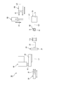
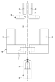
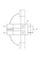
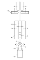
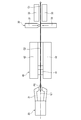
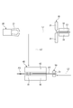
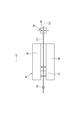
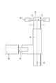
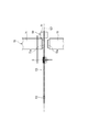
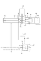
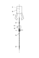
- FIG. 4 It is a schematic side view explaining one Embodiment of the slide fastener assembling apparatus which concerns on this invention. It is a schematic top view of the slide fastener assembling apparatus shown in FIG. It is a surface view explaining an example of a slide fastener. It is a side view of the periphery of a cutting device, a 1st gripper, and a downward transfer apparatus shown in FIG. It is the side view which looked at the downward transfer apparatus shown in FIG. 4 from back. It is a side view explaining the state which a 1st gripper holds a continuous fastener chain and transfers to the front side from the back side of a slide fastener assembly apparatus.
- the upper side is the upper side with respect to the paper surface of FIG. 1
- the lower side is the lower side with respect to the paper surface of FIG. 1
- the front side is with respect to the paper surface of FIG.
- the left side and the rear side are the right side with respect to the paper surface of FIG. 1
- the left side is the front side with respect to the paper surface of FIG. 1
- the right side is the back side with respect to the paper surface of FIG.
- the left-right direction of a slide fastener assembly apparatus is also called the width direction.
- the front side is the front side with respect to the paper surface of FIG. 3
- the back side is the back side with respect to the paper surface of FIG. 3
- the upper side is the upper side with respect to the paper surface of FIG.
- the lower side with respect to the paper surface the left side is the left side with respect to the paper surface of FIG. 3
- the right side is the right side with respect to the paper surface of FIG.
- the left-right direction of a slide fastener is also called the width direction.
- the vertical direction of the slide fastener is also called the length direction.
- the slide fastener assembling apparatus 10 includes a chain reversing unit 11 that reverses the front and back of the supplied continuous fastener chain C1 and the continuous fastener chain C1 of the slide fastener assembling apparatus 10.
- the first to fourth grippers 20, 50, 80, 90 are moving means for moving and transferring the continuous fastener chain C1, the fastener chain C2, and the slide fastener SF in each assembly stage.
- the slider attaching device 60 and the top stopper attaching device 70 are disposed below the cutting device 30.
- the 1st transfer line L1 by the 1st gripper 20 and the 3rd transfer line L3 by the 2nd gripper 50 are provided in parallel up and down.
- a fourth gripper 90 is arranged on the right side in the width direction of the cutting device 30, the slider mounting device 60, and the top stopper mounting device 70.
- the 5th transfer line L5 by the 4th gripper 90 is provided in parallel with the width direction right side of the 1st and 3rd transfer lines L1 and L3.
- the slide fastener SF assembled by the slide fastener assembling apparatus 10 of the present embodiment will be described.
- the slide fastener SF includes a pair of left and right fastener tapes T, a pair of left and right fastener element rows E provided at opposite tape side edges of the pair of left and right fastener tapes T, and a pair of left and right fasteners T.
- the slider S that engages and separates the fastener element rows E, the upper stoppers (stop portions) P1 provided at the upper ends of the pair of left and right fastener element rows E, and the lower ends of the pair of left and right fastener element rows E are provided.
- the fastener element row E is a fastener element row made of synthetic resin injection molding in the present embodiment, but is not limited thereto, and is not limited to a coil-like fastener element row, a zigzag fastener element row, and a metal It may be a fastener element row.
- the bottom stop P2 may be an opening tool composed of a box bar, a box body, and a butterfly bar.
- the continuous fastener chain C1 has a large number of fastener chains C2 to which the fastener element row E and the bottom stop P2 are attached in advance. Moreover, the continuous fastener chain C1 is supplied to the carry-in line L0 of the slide fastener assembly apparatus 10, and this carry-in line L0 is provided above the first transfer line L1. Further, the continuous fastener chain C1 is supplied to the carry-in line L0 of the slide fastener assembling apparatus 10 so that the bottom stopper P2 is on the rear side of the slide fastener assembling apparatus 10 and the surface thereof is on the upper side.
- the fastener chain C2 includes a pair of left and right fastener tapes T and a pair of left and right fastener element rows E, and the pair of left and right fastener element rows E are meshed. 6 to 22, the description of the pair of left and right fastener element rows E is omitted because the drawings are complicated.
- the chain reversing unit 11 includes three guide rollers 11a, 11b, which reverse a continuous fastener chain C1 supplied to the carry-in line L0 from the front side of the slide fastener assembling apparatus 10 in a substantially U shape. 11c, and the continuous fastener chain C1 is supplied to the cutting device 30 from the rear side of the slide fastener assembling apparatus 10.
- the first gripper 20 grips the downstream end portion (left end portion in FIG. 6) of the continuous fastener chain C1 and transfers the continuous fastener chain C1 from the rear side to the front side of the slide fastener assembly apparatus 10 by a predetermined length.
- a gripper 21 that holds the continuous fastener chain C1 and a moving device (not shown) that moves the gripper 21 in the front-rear direction are provided.
- the gripper 21 is configured to move and grip the downstream end portion of the continuous fastener chain C1 from the front side of the slide fastener assembling apparatus 10.
- the continuous fastener chain C1 moves on the first transfer line L1 by the first gripper 20.
- the cutting device 30 guides the blade portion 31 disposed above the first transfer line L1, the base portion 32 disposed below the first transfer line L1, and the continuous fastener chain C1.
- the blade 31 and the base 32 are driven up and down by a cylinder (not shown). And the continuous fastener chain C1 is cut
- the lower transfer device 40 transfers the fastener chain C2 having a predetermined length cut out from the continuous fastener chain C1 to the lower third transfer line L3.
- the first transfer line A base member 41 disposed on the right side in the width direction with respect to L1, a pair of upper and lower clamping plates 42 that are provided so as to be rotatable with respect to the base member 41 and sandwich the continuous fastener chain C1, and the base member 41 in the vertical direction A moving device (not shown) that moves.
- the continuous fastener chain C1 is clamped by the upper and lower clamping plates 42 being closed.
- the lower transfer device 40 is driven so that the cutting device 30 clamps the continuous fastener chain C1 before cutting the continuous fastener chain C1.
- the second gripper 50 grips the downstream end (the right end in FIG. 10) of the fastener chain C2, and attaches the slider S and the upper stopper P1 to the fastener chain C2 to the downstream end of the fastener chain C2.
- a pair of grippers 51 that respectively grip the left and right fastener tapes T of the fastener chain C ⁇ b> 2 and a pair of grippers 51, as shown in FIGS. 10 and 11.
- a moving device (not shown) that moves in the front-rear direction.
- the pair of grippers 51 are configured to grip the left and right fastener tapes T from the outside in the width direction.
- the slider mounting device 60 is disposed below the third transfer line L ⁇ b> 3, and a slider holder 61 in which the slider S is set at the upper end, and the slider S is set in the slider holder 61.
- a slider supply device (not shown).
- the slider holder 61 is driven up and down by a cylinder (not shown). Further, in the present embodiment, the slider S is placed on the slider holder 61 so that the handle attachment portion is on the lower side of the slide fastener assembling apparatus 10 and the guide column is on the rear side of the slide fastener assembling apparatus 10.
- one slider mounting device 60 is used, but two or more slider mounting devices 60 may be used depending on the type of slide fastener to be assembled. Therefore, it is possible to deal with a slide fastener having two or more sliders. For example, it can correspond to a slide fastener having two sliders and a reverse opening tool, or a slide fastener having three sliders.
- the top stopper attaching device 70 is a synthetic resin injection molding device, and as shown in FIGS. 14 and 15, is disposed above the third transfer line L3 and has an upper die 71a on the lower end surface. And a pressing portion 72 disposed below the third transfer line L3 and having a lower mold 72a on the upper end surface. The pressing portion 72 is driven up and down by a cylinder (not shown). Note that the upper mold 71a and the lower mold 72a are respectively formed with cavities for forming the left and right upper stoppers P1.
- the third gripper 80 transfers the slide fastener SF finished with the top stopper P1 attached to the fifth transfer line L5 on the right side in the width direction. As shown in FIGS. 18 and 19, the slide fastener SF is transferred.
- a gripper 81 that grips the gripper so as to cross the width direction, and a moving device (not shown) that moves the gripper 81 in the left-right direction.
- the gripper 81 is configured to grip the slide fastener SF from the right side in the width direction.
- the third gripper 80 is driven so as to grip the slide fastener SF during the injection molding of the top stopper P1 by the top stopper attachment device 70.
- the fourth gripper 90 grips the downstream end portion (right end portion in FIG. 21) of the slide fastener SF and transfers the slide fastener SF to the discharge portion.
- a gripper 91 that holds the fastener SF, and a moving device that moves the gripper 91 in the front-rear direction are provided.
- the gripper 91 is configured to grip the downstream end of the slide fastener SF from the rear side of the slide fastener assembly apparatus 10.
- the downstream end of the continuous fastener chain C1 is gripped by the first gripper 20, and the continuous fastener chain C1 is transferred by a predetermined length from the rear side to the front side of the slide fastener assembling apparatus 10 by the first gripper 20 (first 1 transfer step, see FIG. 6). At this time, the cutting position of the continuous fastener chain C1 is positioned.
- the continuous fastener chain C1 is clamped by closing the upper and lower clamping plates 42 of the lower transfer device 40 (see FIG. 7). At this time, the continuous fastener chain C1 is clamped by the clamping plate 42, and the grip of the continuous fastener chain C1 of the first gripper 20 is released.
- the continuous fastener chain C1 is cut into a fastener chain C2 having a predetermined length by the cutting device 30 (see the cutting step, FIG. 8).
- the fastener chain C2 cut out from the continuous fastener chain C1 is transferred to the third transfer line L3 below the first transfer line L1 by the sandwiching plate 42 of the lower transfer device 40 (second transfer step, see FIG. 9). ).
- the downstream end of the fastener chain C2 is gripped by the second gripper 50 (see FIGS. 10 and 11). Then, the upper and lower clamping plates 42 of the lower transfer device 40 rotate and open when the second gripper 50 transfers the fastener chain C2 in the third transfer line L3, and the next continuous fastener in the first transfer line L1. The chain C1 is raised back to the position where it is clamped.
- the second gripper 50 moves the fastener chain C2 along the third transfer line L3 from the front side to the rear side of the slide fastener assembling apparatus 10 (see the first half of the third transfer step, see FIG. 12).
- the fastener chain C2 passes through the slider S held by the slider holder 61 of the attachment device 60, and the slider S is attached to the fastener chain C2 (see the slider attachment step, see FIG. 13). Note that the transfer by the second gripper 50 does not stop even when the slider S is attached. Further, after the slider S is attached to the fastener chain C2, the slider holder 61 releases the holding of the slider S. Accordingly, the slider S is transferred together with the fastener chain C2.
- the fastener chain C2 is further transferred to the rear side of the slide fastener assembling apparatus 10 by the second gripper 50, and the downstream end of the fastener chain C2 is the upper mold 71a of the injection machine 71 of the top stopper attaching apparatus 70 and the pressing portion.
- the portion 72 is transferred to a predetermined position between the lower molds 72a (see the second half of the third transfer step, see FIG. 14).
- the upper stopper P1 is injection-molded on the fastener chain C2 by the upper stopper attaching device 70, and the fastener chain C2 is finished into a slide fastener SF (see the upper stopper attaching process, see FIG. 15). Further, during the injection molding by the top stopper attaching device 70, the grip of the fastener chain C2 of the second gripper 50 is released, and the second gripper 50 is returned to the position for gripping the next fastener chain C2 (see FIG. 16). ). Further, the slide fastener SF is gripped by the third gripper 80 during the injection molding by the top stopper attaching device 70 (see FIGS. 16 to 18).
- the finished slide fastener SF is transferred by the third gripper 80 to the fifth transfer line L5 on the right side in the width direction separated from the third transfer line L3 (see the fourth transfer step, see FIG. 19).
- the third gripper 80 may transfer the finished slide fastener SF to the left side in the width direction.
- the slide fastener SF is gripped by the fourth gripper 90, the grip of the slide fastener SF of the third gripper 80 is released, and the slide fastener SF is transferred from the third gripper 80 to the fourth gripper 90 (FIG. 20, see FIG.
- the slide fastener SF moves along the fifth transfer line L5 by the fourth gripper 90 and is transferred to the discharge portion (discharge step, see FIG. 22).
- the first gripper 20 and the second gripper 50 are used to perform the first transfer process and the cutting process, the third transfer process, the slider mounting process, and the top stopper mounting process. And in parallel.
- the continuous fastener chain C1 is transferred by the first gripper 20 and the first gripper 20 that transfer the continuous fastener chain C1 from the rear side to the front side.
- the cutting device 30 for cutting the continuous fastener chain C1 into a fastener chain C2 having a predetermined length, the lower transfer device 40 for transferring the cut fastener chain C2 downward, and the fastener chain C2 transferred by the lower transfer device 40 Is transferred by the second gripper 50, the slider mounting device 60 for attaching the slider S to the fastener chain C 2 transferred by the second gripper 50, and the second gripper 50.
- the process until the part P1 is attached and finished into the slide fastener SF can be performed in parallel.
- the slide fastener assembling apparatus 10 of this embodiment since the slider attaching device 60 and the top stopper attaching device 70 are disposed below the cutting device 30, the length of the slide fastener assembling apparatus 10 is shortened.
- the slide fastener assembling apparatus 10 can be downsized.
- the slide fastener assembling apparatus 10 of the present embodiment since the third gripper 80 for transferring the finished slide fastener SF to the right side in the width direction is provided, the completion of injection molding by the top stopper attaching device 70 is awaited.
- the second gripper 50 can be returned to the position for gripping the next fastener chain C2.
- the assembly time of the slide fastener SF can be further shortened.
- this invention is not limited to what was illustrated to the said embodiment, In the range which does not deviate from the summary of this invention, it can change suitably.
- the third gripper 80 and the fourth gripper 90 may be eliminated, and the slide fastener SF may be discharged by the second gripper 50.
- the slide fastener SF may be discharged by a roll device including a driving roller and a guide roller.
- slide fastener assembling apparatus 20 first gripper (first moving means) 30 cutting device 40 downward transfer device 50 second gripper (second moving means) 60 Slider mounting device 70 Upper stopper mounting device (stop mounting device) 80 Third gripper (third moving means) 90 Fourth gripper (fourth moving means) C1 Continuous fastener chain C2 Fastener chain SF Slide fastener P1 Top stop (stop)
Landscapes
- Slide Fasteners (AREA)
Abstract
スライドファスナーの組立時間を短縮することができ、また、スライドファスナー組立装置を小型化することができるスライドファスナー組立装置を提供する。連続ファスナーチェーン(C1)をスライドファスナー組立装置(10)の後方側から前方側に移送する第1移動手段(20)と、第1移動手段(20)により移送された連続ファスナーチェーン(C1)を所定長さのファスナーチェーン(C2)にカットする切断装置(30)と、ファスナーチェーン(C2)を下方に移送する下方移送装置(40)と、下方移送装置(40)により移送されたファスナーチェーン(C2)をスライドファスナー組立装置(10)の前方側から後方側に移送する第2移動手段(50)と、第2移動手段(20)により移送されるファスナーチェーン(C2)にスライダー(S)を取り付けるスライダー取付装置(60)と、第2移動手段(20)により移送されたファスナーチェーン(C2)に止部(P1)を取り付ける止部取付装置(70)と、を備え、切断装置(30)の下方にスライダー取付装置(60)及び止部取付装置(70)を配置する。
Description
この発明は、連続ファスナーチェーンに順次加工を加えてスライドファスナーに仕上げるスライドファスナー組立装置に関する。
従来のスライドファスナー組立装置としては、連続ファスナーチェーンを所定長さ移送する移送グリッパと、移送された連続ファスナーチェーンをカットする切断装置と、カットされたファスナーチェーンにスライダーを取り付けるスライダー取付装置と、カットされたファスナーチェーンに上止部を取り付ける上止部取付装置と、仕上げられたスライドファスナーを排出する排出装置と、を備えるものが知られている(例えば、特許文献1参照)。
しかしながら、上記特許文献1に記載のスライドファスナー組立装置では、1つの移送グリッパで移送を行っているため、移送グリッパの移動距離が長く、切断装置、スライダー取付装置、及び上止部取付装置の待機時間が長くなってしまい、スライドファスナーの組立時間が長くなってしまっていた。また、連続ファスナーチェーンを所定長さ移送して切断するまでの間は、スライダー取付装置及び上止部取付装置が待機し、スライダー及び上止部が取り付けられ排出されるまでの間は、切断装置が待機しているため、スライドファスナーの組立時間が長くなってしまっていた。さらに、切断装置、スライダー取付装置、及び上止部取付装置が直線的に並んで配置されているため、スライドファスナー組立装置が大型化してしまっていた。
本発明は、前述した課題に鑑みてなされたものであり、その目的は、切断装置、スライダー取付装置、及び上止部取付装置の待機時間を短くして、スライドファスナーの組立時間を短縮することができ、また、スライドファスナー組立装置を小型化することができるスライドファスナー組立装置を提供することにある。
本発明の上記目的は、下記の構成により達成される。
(1)連続ファスナーチェーンをスライドファスナー組立装置の後方側から前方側に移送する第1移動手段と、第1移動手段により移送された連続ファスナーチェーンを所定長さのファスナーチェーンにカットする切断装置と、ファスナーチェーンを下方に移送する下方移送装置と、下方移送装置により移送されたファスナーチェーンをスライドファスナー組立装置の前方側から後方側に移送する第2移動手段と、第2移動手段により移送されるファスナーチェーンにスライダーを取り付ける少なくとも1つのスライダー取付装置と、第2移動手段により移送されたファスナーチェーンに止部を取り付ける止部取付装置と、を備え、切断装置の下方にスライダー取付装置及び止部取付装置を配置することを特徴とするスライドファスナー組立装置。
(2)止部が取り付けられて仕上げられたスライドファスナーを幅方向に移送する第3移動手段を備えることを特徴とする(1)に記載のスライドファスナー組立装置。
(3)第3移動手段により移送されたスライドファスナーを排出部に移送する第4移動手段を備えることを特徴とする(2)に記載のスライドファスナー組立装置。
(1)連続ファスナーチェーンをスライドファスナー組立装置の後方側から前方側に移送する第1移動手段と、第1移動手段により移送された連続ファスナーチェーンを所定長さのファスナーチェーンにカットする切断装置と、ファスナーチェーンを下方に移送する下方移送装置と、下方移送装置により移送されたファスナーチェーンをスライドファスナー組立装置の前方側から後方側に移送する第2移動手段と、第2移動手段により移送されるファスナーチェーンにスライダーを取り付ける少なくとも1つのスライダー取付装置と、第2移動手段により移送されたファスナーチェーンに止部を取り付ける止部取付装置と、を備え、切断装置の下方にスライダー取付装置及び止部取付装置を配置することを特徴とするスライドファスナー組立装置。
(2)止部が取り付けられて仕上げられたスライドファスナーを幅方向に移送する第3移動手段を備えることを特徴とする(1)に記載のスライドファスナー組立装置。
(3)第3移動手段により移送されたスライドファスナーを排出部に移送する第4移動手段を備えることを特徴とする(2)に記載のスライドファスナー組立装置。
本発明によれば、連続ファスナーチェーンをスライドファスナー組立装置の後方側から前方側に移送する第1移動手段と、第1移動手段により移送された連続ファスナーチェーンを所定長さのファスナーチェーンにカットする切断装置と、ファスナーチェーンを下方に移送する下方移送装置と、下方移送装置により移送されたファスナーチェーンをスライドファスナー組立装置の前方側から後方側に移送する第2移動手段と、第2移動手段により移送されるファスナーチェーンにスライダーを取り付ける少なくとも1つのスライダー取付装置と、第2移動手段により移送されたファスナーチェーンに止部を取り付ける止部取付装置と、を備えるため、連続ファスナーチェーンが所定長さのファスナーチェーンにカットされるまでの工程と、カットされたファスナーチェーンにスライダー及び止部が取り付けられ、スライドファスナーに仕上げられるまでの工程と、を並行して行うことができる。これにより、切断装置、スライダー取付装置、及び止部取付装置の待機時間を短くすることができるので、スライドファスナーの組立時間を短縮することができる。また、切断装置の下方にスライダー取付装置及び止部取付装置を配置するため、スライドファスナー組立装置の前後長さを短くすることができ、スライドファスナー組立装置を小型化することができる。
以下、本発明に係るスライドファスナー組立装置の一実施形態について、図面に基づいて詳細に説明する。なお、以後の説明において、スライドファスナー組立装置に関しては、上側とは図1の紙面に対して上側、下側とは図1の紙面に対して下側、前側とは図1の紙面に対して左側、後側とは図1の紙面に対して右側、左側とは図1の紙面に対して手前側、右側とは図1の紙面に対して奥側とする。また、スライドファスナー組立装置の左右方向は幅方向とも言う。スライドファスナーに関しては、表側とは図3の紙面に対して手前側、裏側とは図3の紙面に対して奥側、上側とは図3の紙面に対して上側、下側とは図3の紙面に対して下側、左側とは図3の紙面に対して左側、右側とは図3の紙面に対して右側とする。また、スライドファスナーの左右方向は幅方向とも言う。また、スライドファスナーの上下方向は長さ方向とも言う。
本実施形態のスライドファスナー組立装置10は、図1及び図2に示すように、供給された連続ファスナーチェーンC1の表裏を反転させるチェーン反転部11と、連続ファスナーチェーンC1をスライドファスナー組立装置10の後方側から前方側に移送する第1グリッパ(第1移動手段)20と、第1グリッパ20により移送された連続ファスナーチェーンC1を所定長さのファスナーチェーンC2にカットする切断装置30と、カットされたファスナーチェーンC2を下方に移送する下方移送装置40と、下方移送装置40により移送されたファスナーチェーンC2をスライドファスナー組立装置10の前方側から後方側に移送する第2グリッパ(第2移動手段)50と、第2グリッパ50により移送されるファスナーチェーンC2にスライダーSを取り付けるスライダー取付装置60と、第2グリッパ50により移送されたファスナーチェーンC2に上止部P1を取り付ける上止部取付装置70と、上止部P1が取り付けられて仕上げられたスライドファスナーSFを幅方向右側に移送する第3グリッパ(第3移動手段)80と、第3グリッパ80により移送されたスライドファスナーSFを不図示の排出部に移送する第4グリッパ90(第4移動手段)と、を備える。
なお、図1及び図2中の符号L1は、第1グリッパ20による第1移送ラインであり、符合L2は、下方移送装置40による第2移送ラインであり、符合L3は、第2グリッパ50による第3移送ラインであり、符合L4は、第3グリッパ80による第4移送ラインであり、符合L5は、第4グリッパ90による第5移送ラインである。また、第1~第4グリッパ20,50,80,90は、各組立段階において連続ファスナーチェーンC1、ファスナーチェーンC2、スライドファスナーSFを移動、移送させる移動手段である。
また、本実施形態のスライドファスナー組立装置10では、切断装置30の下方にスライダー取付装置60及び上止部取付装置70が配置されている。このため、第1グリッパ20による第1移送ラインL1と第2グリッパ50による第3移送ラインL3は、上下に平行に設けられている。また、切断装置30、スライダー取付装置60、及び上止部取付装置70の幅方向右側に第4グリッパ90が配置されている。このため、第4グリッパ90による第5移送ラインL5は、第1及び第3移送ラインL1,L3の幅方向右側に平行に設けられている。
ここで、本実施形態のスライドファスナー組立装置10で組み立てられるスライドファスナーSFについて説明する。このスライドファスナーSFは、図3に示すように、左右一対のファスナーテープTと、左右一対のファスナーテープTの対向するテープ側縁部にそれぞれ設けられる左右一対のファスナーエレメント列Eと、左右一対のファスナーエレメント列Eを噛合・分離させるスライダーSと、左右一対のファスナーエレメント列Eの上端部にそれぞれ設けられる上止部(止部)P1と、左右一対のファスナーエレメント列Eの下端部に設けられる下止部(止部)P2と、を備える。
なお、ファスナーエレメント列Eは、本実施形態では合成樹脂の射出成形からなるファスナーエレメント列であるが、これに限定されず、コイル状のファスナーエレメント列、ジグザグ状のファスナーエレメント列、及び金属製のファスナーエレメント列であってもよい。また、下止部P2は、箱棒、箱体、及び蝶棒からなる開き具であってもよい。
また、連続ファスナーチェーンC1は、ファスナーエレメント列E及び下止部P2が予め取り付けられたファスナーチェーンC2を多数連続して有するものである。また、連続ファスナーチェーンC1は、スライドファスナー組立装置10の搬入ラインL0に供給されており、この搬入ラインL0は、第1移送ラインL1の上側に設けられている。また、連続ファスナーチェーンC1は、スライドファスナー組立装置10の搬入ラインL0に、下止部P2がスライドファスナー組立装置10の後方側となるように、且つその表面が上側となるように供給される。また、ファスナーチェーンC2は、左右一対のファスナーテープTと左右一対のファスナーエレメント列Eからなり、左右一対のファスナーエレメント列Eは噛合されている。なお、図6~図22では、左右一対のファスナーエレメント列Eの記載は、図面が煩雑になるため省略されている。
チェーン反転部11は、図1に示すように、スライドファスナー組立装置10の前方側から搬入ラインL0に供給される連続ファスナーチェーンC1を略U字状に反転する3個のガイドローラー11a,11b,11cから構成されており、スライドファスナー組立装置10の後方側から連続ファスナーチェーンC1を切断装置30に供給する。
第1グリッパ20は、連続ファスナーチェーンC1の下流側端部(図6の左側端部)を把持し、連続ファスナーチェーンC1をスライドファスナー組立装置10の後方側から前方側に所定長さ移送するものであり、図4に示すように、連続ファスナーチェーンC1を把持するグリッパ21と、グリッパ21を前後方向に移動する不図示の移動装置と、を備える。また、グリッパ21は、連続ファスナーチェーンC1の下流側端部をスライドファスナー組立装置10の前方側から移動し把持するように構成されている。連続ファスナーチェーンC1は、第1グリッパ20によって第1移送ラインL1を移動する。
切断装置30は、図4に示すように、第1移送ラインL1より上方に配置される刃部31と、第1移送ラインL1より下方に配置される台部32と、連続ファスナーチェーンC1を案内する上下一対のチェーンガイドプレート33と、を備える。また、刃部31及び台部32は、不図示のシリンダによりそれぞれ上下に駆動される。そして、台部32が上動して、刃部31が下動することにより、連続ファスナーチェーンC1が切断される。
下方移送装置40は、連続ファスナーチェーンC1から切り出された所定長さのファスナーチェーンC2を下方の第3移送ラインL3に移送するものであり、図4及び図5に示すように、第1移送ラインL1よりも幅方向右側に配置されるベース部材41と、ベース部材41に対して回動可能に設けられ、連続ファスナーチェーンC1を挟持する上下一対の挟持プレート42と、ベース部材41を上下方向に移動する不図示の移動装置と、を備える。そして、上下の挟持プレート42が閉じることにより、連続ファスナーチェーンC1が挟持される。なお、下方移送装置40は、切断装置30が連続ファスナーチェーンC1をカットする前に連続ファスナーチェーンC1を挟持するように駆動されている。
第2グリッパ50は、ファスナーチェーンC2の下流側端部(図10の右側端部)を把持し、ファスナーチェーンC2にスライダーS及び上止部P1に取り付けるために、ファスナーチェーンC2の下流側端部を上止部取付装置70の所定位置に移送するものであり、図10及び図11に示すように、ファスナーチェーンC2の左右のファスナーテープTをそれぞれ把持する一対のグリッパ51と、一対のグリッパ51を前後方向に移動する不図示の移動装置と、を備える。また、一対のグリッパ51は、左右のファスナーテープTを幅方向外側から把持するように構成されている。
スライダー取付装置60は、図12及び図13に示すように、第3移送ラインL3より下方に配置され、上端部にスライダーSがセットされるスライダーホルダ61と、スライダーホルダ61にスライダーSをセットする不図示のスライダー供給装置と、を備える。スライダーホルダ61は、不図示のシリンダにより上下に駆動される。また、本実施形態では、スライダーSは、スライダーホルダ61に、引手取付部がスライドファスナー組立装置10の下方側、且つ案内柱がスライドファスナー組立装置10の後方側となるように置かれる。
なお、本実施形態では、スライダー取付装置60を1台使用しているが、組み立てるスライドファスナーの種類に応じて2台以上使用してもよい。従って、スライダーを2個以上有するスライドファスナーにも対応することが可能である。例えば、スライダー2個と逆開き具を有するスライドファスナーや、スライダーを3個有するスライドファスナーに対応することができる。
上止部取付装置70は、合成樹脂の射出成形装置であり、図14及び図15に示すように、第3移送ラインL3より上方に配置され、下端面に上金型71aを有する射出機71と、第3移送ラインL3より下方に配置され、上端面に下金型72aを有する押圧部72と、を備える。また、押圧部72は、不図示のシリンダにより上下に駆動される。なお、上金型71a及び下金型72aには、左右の上止部P1を成形するためのキャビティがそれぞれ形成されている。
第3グリッパ80は、上止部P1が取り付けられて仕上げられたスライドファスナーSFを幅方向右側の第5移送ラインL5に移送するものであり、図18及び図19に示すように、スライドファスナーSFを幅方向に横断するように把持するグリッパ81と、グリッパ81を左右方向に移動する不図示の移動装置と、を備える。また、グリッパ81は、スライドファスナーSFを幅方向右側から把持するように構成されている。なお、第3グリッパ80は、上止部取付装置70による上止部P1の射出成形中にスライドファスナーSFを把持するように駆動されている。
第4グリッパ90は、スライドファスナーSFの下流側端部(図21の右側端部)を把持し、スライドファスナーSFを排出部に移送するものであり、図20~図22に示すように、スライドファスナーSFを把持するグリッパ91と、グリッパ91を前後方向に移動する移動装置と、を備える。また、グリッパ91は、スライドファスナーSFの下流側端部をスライドファスナー組立装置10の後方側から把持するように構成されている。
次に、図6~図22を参照して、スライドファスナー組立装置10の動作について説明する。
まず、第1グリッパ20により連続ファスナーチェーンC1の下流側端部が把持され、第1グリッパ20により連続ファスナーチェーンC1がスライドファスナー組立装置10の後方側から前方側に所定長さ移送される(第1移送工程、図6参照)。また、このとき、連続ファスナーチェーンC1の切断位置の位置決めが行われる。
次いで、下方移送装置40の上下の挟持プレート42が閉じることにより連続ファスナーチェーンC1が挟持される(図7参照)。また、このとき、挟持プレート42で連続ファスナーチェーンC1を挟持し、第1グリッパ20の連続ファスナーチェーンC1の把持が解除される。
次いで、切断装置30により連続ファスナーチェーンC1が所定長さのファスナーチェーンC2にカットされる(切断工程、図8参照)。
次いで、連続ファスナーチェーンC1から切り出されたファスナーチェーンC2が下方移送装置40の挟持プレート42により第1移送ラインL1よりも下方の第3移送ラインL3に移送される(第2移送工程、図9参照)。
次いで、第2グリッパ50によりファスナーチェーンC2の下流側端部が把持される(図10、図11参照)。そして、下方移送装置40の上下の挟持プレート42は、第3移送ラインL3で第2グリッパ50がファスナーチェーンC2を移送するときに回動して開いて、第1移送ラインL1で次の連続ファスナーチェーンC1を挟持する位置に上昇し戻される。
次いで、第2グリッパ50によりファスナーチェーンC2がスライドファスナー組立装置10の前方側から後方側に第3移送ラインL3を移送され(第3移送工程前半、図12参照)、その移送の途中において、スライダー取付装置60のスライダーホルダ61に保持されているスライダーS内をファスナーチェーンC2が通過して、ファスナーチェーンC2にスライダーSが取り付けられる(スライダー取り付け工程、図13参照)。なお、第2グリッパ50による移送は、スライダーSの取り付け中も停止することはない。また、スライダーSがファスナーチェーンC2に取り付けられた後、スライダーホルダ61はスライダーSの保持を解除する。従って、スライダーSは、ファスナーチェーンC2と共に移送される。
次いで、第2グリッパ50によりファスナーチェーンC2が更にスライドファスナー組立装置10の後方側に移送され、ファスナーチェーンC2の下流側端部が上止部取付装置70の射出機71の上金型71a及び押圧部72の下金型72a間の所定位置に移送される(第3移送工程後半、図14参照)。
次いで、上止部取付装置70によりファスナーチェーンC2に上止部P1が射出成形され、ファスナーチェーンC2がスライドファスナーSFに仕上げられる(上止部取り付け工程、図15参照)。また、上止部取付装置70による射出成形中に、第2グリッパ50のファスナーチェーンC2の把持が解除され、第2グリッパ50は、次のファスナーチェーンC2を把持する位置に戻される(図16参照)。さらに、上止部取付装置70による射出成形中に、第3グリッパ80によりスライドファスナーSFが把持される(図16~図18参照)。
次いで、仕上げられたスライドファスナーSFが第3グリッパ80により第3移送ラインL3と離間した幅方向右側の第5移送ラインL5に移送される(第4移送工程、図19参照)。なお、第4グリッパ90が上止部取付装置70の幅方向左側に配置されている場合、第3グリッパ80は、仕上げられたスライドファスナーSFを幅方向左側に移送してもよい。
次いで、第4グリッパ90によりスライドファスナーSFが把持されると共に、第3グリッパ80のスライドファスナーSFの把持が解除されて、第3グリッパ80から第4グリッパ90にスライドファスナーSFが受け渡される(図20、図21参照)。
次いで、第4グリッパ90によりスライドファスナーSFが第5移送ラインL5を移動して排出部に移送される(排出工程、図22参照)。
このように、本実施形態のスライドファスナー組立装置10では、第1グリッパ20及び第2グリッパ50によって、第1移送工程及び切断工程と、第3移送工程、スライダー取り付け工程、及び上止部取り付け工程と、を並行して行っている。
以上説明したように、本実施形態のスライドファスナー組立装置10によれば、連続ファスナーチェーンC1をスライドファスナー組立装置10の後方側から前方側に移送する第1グリッパ20と、第1グリッパ20により移送された連続ファスナーチェーンC1を所定長さのファスナーチェーンC2にカットする切断装置30と、カットされたファスナーチェーンC2を下方に移送する下方移送装置40と、下方移送装置40により移送されたファスナーチェーンC2をスライドファスナー組立装置10の前方側から後方側に移送する第2グリッパ50と、第2グリッパ50により移送されるファスナーチェーンC2にスライダーSを取り付けるスライダー取付装置60と、第2グリッパ50により移送されたファスナーチェーンC2に上止部P1を取り付ける上止部取付装置70と、を備えるため、連続ファスナーチェーンC1が所定長さのファスナーチェーンC2にカットされるまでの工程と、カットされたファスナーチェーンC2にスライダーS及び上止部P1が取り付けられ、スライドファスナーSFに仕上げられるまでの工程と、を並行して行うことができる。これにより、切断装置30、スライダー取付装置60、及び上止部取付装置70の待機時間を短くすることができるので、スライドファスナーSFの組立時間を短縮することができる。
また、本実施形態のスライドファスナー組立装置10によれば、切断装置30の下方にスライダー取付装置60及び上止部取付装置70を配置するため、スライドファスナー組立装置10の前後長さを短くすることができ、スライドファスナー組立装置10を小型化することができる。
また、本実施形態のスライドファスナー組立装置10によれば、仕上げられたスライドファスナーSFを幅方向右側に移送する第3グリッパ80を備えるため、上止部取付装置70による射出成形の完了を待つことなく、第2グリッパ50を次のファスナーチェーンC2を把持する位置に戻すことができる。これにより、切断装置30、スライダー取付装置60、及び上止部取付装置70の待機時間を更に短くすることができるので、スライドファスナーSFの組立時間を更に短縮することができる。
なお、本発明は上記実施形態に例示したものに限定されるものではなく、本発明の要旨を逸脱しない範囲において適宜変更可能である。
例えば、第3グリッパ80及び第4グリッパ90をなくして、第2グリッパ50によりスライドファスナーSFを排出してもよい。
また、スライドファスナーSFを排出する第4グリッパ90の代わりに、駆動ローラーとガイドローラーからなるロール装置によりスライドファスナーSFを排出してもよい。
例えば、第3グリッパ80及び第4グリッパ90をなくして、第2グリッパ50によりスライドファスナーSFを排出してもよい。
また、スライドファスナーSFを排出する第4グリッパ90の代わりに、駆動ローラーとガイドローラーからなるロール装置によりスライドファスナーSFを排出してもよい。
10 スライドファスナー組立装置
20 第1グリッパ(第1移動手段)
30 切断装置
40 下方移送装置
50 第2グリッパ(第2移動手段)
60 スライダー取付装置
70 上止部取付装置(止部取付装置)
80 第3グリッパ(第3移動手段)
90 第4グリッパ(第4移動手段)
C1 連続ファスナーチェーン
C2 ファスナーチェーン
SF スライドファスナー
P1 上止部(止部)
20 第1グリッパ(第1移動手段)
30 切断装置
40 下方移送装置
50 第2グリッパ(第2移動手段)
60 スライダー取付装置
70 上止部取付装置(止部取付装置)
80 第3グリッパ(第3移動手段)
90 第4グリッパ(第4移動手段)
C1 連続ファスナーチェーン
C2 ファスナーチェーン
SF スライドファスナー
P1 上止部(止部)
Claims (3)
- 連続ファスナーチェーン(C1)をスライドファスナー組立装置(10)の後方側から前方側に移送する第1移動手段(20)と、
前記第1移動手段(20)により移送された前記連続ファスナーチェーン(C1)を所定長さのファスナーチェーン(C2)にカットする切断装置(30)と、
前記ファスナーチェーン(C2)を下方に移送する下方移送装置(40)と、
前記下方移送装置(40)により移送された前記ファスナーチェーン(C2)をスライドファスナー組立装置(10)の前方側から後方側に移送する第2移動手段(50)と、
前記第2移動手段(50)により移送される前記ファスナーチェーン(C2)にスライダー(S)を取り付ける少なくとも1つのスライダー取付装置(60)と、
前記第2移動手段(50)により移送された前記ファスナーチェーン(C2)に止部(P1)を取り付ける止部取付装置(70)と、を備え、
前記切断装置(30)の下方に前記スライダー取付装置(60)及び前記止部取付装置(70)を配置することを特徴とするスライドファスナー組立装置(10)。 - 前記止部(P1)が取り付けられて仕上げられたスライドファスナー(SF)を幅方向に移送する第3移動手段(80)を備えることを特徴とする請求項1に記載のスライドファスナー組立装置(10)。
- 前記第3移動手段(80)により移送された前記スライドファスナー(SF)を排出部に移送する第4移動手段(90)を備えることを特徴とする請求項2に記載のスライドファスナー組立装置(10)。
Priority Applications (3)
| Application Number | Priority Date | Filing Date | Title |
|---|---|---|---|
| CN201480000809.2A CN104379227B (zh) | 2014-01-20 | 2014-01-20 | 拉链组装装置 |
| PCT/JP2014/051018 WO2015107699A1 (ja) | 2014-01-20 | 2014-01-20 | スライドファスナー組立装置 |
| TW103135133A TWI503087B (zh) | 2014-01-20 | 2014-10-09 | 拉鏈組裝裝置 |
Applications Claiming Priority (1)
| Application Number | Priority Date | Filing Date | Title |
|---|---|---|---|
| PCT/JP2014/051018 WO2015107699A1 (ja) | 2014-01-20 | 2014-01-20 | スライドファスナー組立装置 |
Publications (1)
| Publication Number | Publication Date |
|---|---|
| WO2015107699A1 true WO2015107699A1 (ja) | 2015-07-23 |
Family
ID=52557525
Family Applications (1)
| Application Number | Title | Priority Date | Filing Date |
|---|---|---|---|
| PCT/JP2014/051018 Ceased WO2015107699A1 (ja) | 2014-01-20 | 2014-01-20 | スライドファスナー組立装置 |
Country Status (3)
| Country | Link |
|---|---|
| CN (1) | CN104379227B (ja) |
| TW (1) | TWI503087B (ja) |
| WO (1) | WO2015107699A1 (ja) |
Cited By (3)
| Publication number | Priority date | Publication date | Assignee | Title |
|---|---|---|---|---|
| CN112293876A (zh) * | 2019-10-18 | 2021-02-02 | 深圳市冠众科技有限公司 | 连续拉链带掉头、切断单元以及采用该单元的拉链制造设备 |
| TWI718660B (zh) * | 2018-12-27 | 2021-02-11 | 日商Ykk股份有限公司 | 拉頭安裝裝置 |
| CN112704305A (zh) * | 2020-12-29 | 2021-04-27 | 安徽星星服装股份有限公司 | 一种背靠背双拉链头的安装装置 |
Families Citing this family (4)
| Publication number | Priority date | Publication date | Assignee | Title |
|---|---|---|---|---|
| CN106913021B (zh) * | 2015-12-24 | 2019-11-08 | Ykk株式会社 | 用于将拉链链条的链牙列插入拉头的装置及方法 |
| CN107549939B (zh) * | 2016-06-30 | 2021-02-02 | Ykk株式会社 | 拉链制造装置及拉链的制造方法 |
| CN109106010B (zh) * | 2017-06-23 | 2022-01-14 | Ykk株式会社 | 拉链的制造装置及拉链的制造方法 |
| CN116784576B (zh) * | 2022-03-14 | 2026-02-13 | Ykk株式会社 | 拉头穿通机构 |
Citations (5)
| Publication number | Priority date | Publication date | Assignee | Title |
|---|---|---|---|---|
| JPS6264304A (ja) * | 1985-07-13 | 1987-03-23 | オプテイ、パテント−、フオルシユングス−、ウント、フアブリカ−ツイオ−ンス、アクチエンゲゼルシヤフト | 末端部材、スライダ及び場合により出発部材を備えた、連結されたフアスナ−を製造する方法及び最終取付け自動装置 |
| JPH0274207A (ja) * | 1988-07-28 | 1990-03-14 | Opti Patent Forsch & Fab Ag | 長い連続スライドファスナ帯片にランナをはめる装置 |
| JPH02291804A (ja) * | 1989-05-01 | 1990-12-03 | Yoshida Kogyo Kk <Ykk> | スライドファスナーの上止め具取付け装置 |
| JP2005102715A (ja) * | 2003-09-26 | 2005-04-21 | Ykk Corp | スライドファスナーの製造装置 |
| JP2006223482A (ja) * | 2005-02-16 | 2006-08-31 | Ykk Corp | スライドファスナーの連続仕上装置 |
-
2014
- 2014-01-20 CN CN201480000809.2A patent/CN104379227B/zh active Active
- 2014-01-20 WO PCT/JP2014/051018 patent/WO2015107699A1/ja not_active Ceased
- 2014-10-09 TW TW103135133A patent/TWI503087B/zh active
Patent Citations (5)
| Publication number | Priority date | Publication date | Assignee | Title |
|---|---|---|---|---|
| JPS6264304A (ja) * | 1985-07-13 | 1987-03-23 | オプテイ、パテント−、フオルシユングス−、ウント、フアブリカ−ツイオ−ンス、アクチエンゲゼルシヤフト | 末端部材、スライダ及び場合により出発部材を備えた、連結されたフアスナ−を製造する方法及び最終取付け自動装置 |
| JPH0274207A (ja) * | 1988-07-28 | 1990-03-14 | Opti Patent Forsch & Fab Ag | 長い連続スライドファスナ帯片にランナをはめる装置 |
| JPH02291804A (ja) * | 1989-05-01 | 1990-12-03 | Yoshida Kogyo Kk <Ykk> | スライドファスナーの上止め具取付け装置 |
| JP2005102715A (ja) * | 2003-09-26 | 2005-04-21 | Ykk Corp | スライドファスナーの製造装置 |
| JP2006223482A (ja) * | 2005-02-16 | 2006-08-31 | Ykk Corp | スライドファスナーの連続仕上装置 |
Cited By (4)
| Publication number | Priority date | Publication date | Assignee | Title |
|---|---|---|---|---|
| TWI718660B (zh) * | 2018-12-27 | 2021-02-11 | 日商Ykk股份有限公司 | 拉頭安裝裝置 |
| CN112293876A (zh) * | 2019-10-18 | 2021-02-02 | 深圳市冠众科技有限公司 | 连续拉链带掉头、切断单元以及采用该单元的拉链制造设备 |
| CN112704305A (zh) * | 2020-12-29 | 2021-04-27 | 安徽星星服装股份有限公司 | 一种背靠背双拉链头的安装装置 |
| CN112704305B (zh) * | 2020-12-29 | 2022-01-21 | 安徽星星服装股份有限公司 | 一种背靠背双拉链头的安装装置 |
Also Published As
| Publication number | Publication date |
|---|---|
| CN104379227B (zh) | 2016-11-09 |
| TWI503087B (zh) | 2015-10-11 |
| TW201528998A (zh) | 2015-08-01 |
| CN104379227A (zh) | 2015-02-25 |
Similar Documents
| Publication | Publication Date | Title |
|---|---|---|
| CN104379227B (zh) | 拉链组装装置 | |
| WO2014061089A1 (ja) | スライドファスナー組立装置 | |
| CN104703771B (zh) | 止挡构件成形装置 | |
| CN105592947B (zh) | 用于弯曲成型段如管的装置 | |
| CN102601254B (zh) | 一种冲压多工位同步气动机械手 | |
| JP4064326B2 (ja) | スライドファスナーの製造装置 | |
| JP2007267828A (ja) | スライダーの挿通方法及びスライダーの挿通装置 | |
| WO2015092868A1 (ja) | スライドファスナー組立装置 | |
| TW201739536A (zh) | 用於傳送工作件的運輸方法 | |
| CN108405686A (zh) | 折弯机的随动装置 | |
| TWI573538B (zh) | 反開式拉鏈的製造方法及製造裝置 | |
| JP2005153123A (ja) | グリッパ装置とそのグリッパ装置を用いたワーク搬送装置 | |
| TW201739535A (zh) | 用於在加工裝置中傳送工作件的運輸裝置 | |
| CN204861538U (zh) | 拉链组装装置的链齿咬合装置 | |
| WO2016101574A1 (zh) | 一种卧式压铸机的接料装置 | |
| CN211440993U (zh) | 一种自动取件及水口辅助剪切装置 | |
| CN104507348B (zh) | 增强膜粘着装置 | |
| JP2011156619A (ja) | 加工装置 | |
| JP2003112341A (ja) | 射出成形装置 | |
| CN117380443A (zh) | 一种点胶针头清胶装置及针头清洁方法 | |
| JPS63242511A (ja) | 射出成形機 | |
| JPS6344362B2 (ja) | ||
| CN209207894U (zh) | 一站式注塑及装配的模具系统 | |
| JPS6334726B2 (ja) | ||
| TW202015972A (zh) | 袋體連續性定位輸送裝置 |
Legal Events
| Date | Code | Title | Description |
|---|---|---|---|
| 121 | Ep: the epo has been informed by wipo that ep was designated in this application |
Ref document number: 14878611 Country of ref document: EP Kind code of ref document: A1 |
|
| WWE | Wipo information: entry into national phase |
Ref document number: 2015/11667 Country of ref document: TR |
|
| NENP | Non-entry into the national phase |
Ref country code: DE |
|
| 122 | Ep: pct application non-entry in european phase |
Ref document number: 14878611 Country of ref document: EP Kind code of ref document: A1 |
|
| NENP | Non-entry into the national phase |
Ref country code: JP |