WO2015104909A1 - 内燃機関のノッキング判定装置及びノッキング制御装置 - Google Patents
内燃機関のノッキング判定装置及びノッキング制御装置 Download PDFInfo
- Publication number
- WO2015104909A1 WO2015104909A1 PCT/JP2014/081002 JP2014081002W WO2015104909A1 WO 2015104909 A1 WO2015104909 A1 WO 2015104909A1 JP 2014081002 W JP2014081002 W JP 2014081002W WO 2015104909 A1 WO2015104909 A1 WO 2015104909A1
- Authority
- WO
- WIPO (PCT)
- Prior art keywords
- knocking
- internal combustion
- combustion engine
- knock
- value
- Prior art date
Links
Images

Classifications
-
- F—MECHANICAL ENGINEERING; LIGHTING; HEATING; WEAPONS; BLASTING
- F02—COMBUSTION ENGINES; HOT-GAS OR COMBUSTION-PRODUCT ENGINE PLANTS
- F02D—CONTROLLING COMBUSTION ENGINES
- F02D35/00—Controlling engines, dependent on conditions exterior or interior to engines, not otherwise provided for
- F02D35/02—Controlling engines, dependent on conditions exterior or interior to engines, not otherwise provided for on interior conditions
- F02D35/027—Controlling engines, dependent on conditions exterior or interior to engines, not otherwise provided for on interior conditions using knock sensors
-
- F—MECHANICAL ENGINEERING; LIGHTING; HEATING; WEAPONS; BLASTING
- F02—COMBUSTION ENGINES; HOT-GAS OR COMBUSTION-PRODUCT ENGINE PLANTS
- F02D—CONTROLLING COMBUSTION ENGINES
- F02D35/00—Controlling engines, dependent on conditions exterior or interior to engines, not otherwise provided for
- F02D35/02—Controlling engines, dependent on conditions exterior or interior to engines, not otherwise provided for on interior conditions
- F02D35/023—Controlling engines, dependent on conditions exterior or interior to engines, not otherwise provided for on interior conditions by determining the cylinder pressure
-
- F—MECHANICAL ENGINEERING; LIGHTING; HEATING; WEAPONS; BLASTING
- F02—COMBUSTION ENGINES; HOT-GAS OR COMBUSTION-PRODUCT ENGINE PLANTS
- F02D—CONTROLLING COMBUSTION ENGINES
- F02D41/00—Electrical control of supply of combustible mixture or its constituents
- F02D41/02—Circuit arrangements for generating control signals
- F02D41/04—Introducing corrections for particular operating conditions
- F02D41/042—Introducing corrections for particular operating conditions for stopping the engine
-
- F—MECHANICAL ENGINEERING; LIGHTING; HEATING; WEAPONS; BLASTING
- F02—COMBUSTION ENGINES; HOT-GAS OR COMBUSTION-PRODUCT ENGINE PLANTS
- F02D—CONTROLLING COMBUSTION ENGINES
- F02D41/00—Electrical control of supply of combustible mixture or its constituents
- F02D41/02—Circuit arrangements for generating control signals
- F02D41/04—Introducing corrections for particular operating conditions
- F02D41/12—Introducing corrections for particular operating conditions for deceleration
-
- F—MECHANICAL ENGINEERING; LIGHTING; HEATING; WEAPONS; BLASTING
- F02—COMBUSTION ENGINES; HOT-GAS OR COMBUSTION-PRODUCT ENGINE PLANTS
- F02D—CONTROLLING COMBUSTION ENGINES
- F02D41/00—Electrical control of supply of combustible mixture or its constituents
- F02D41/22—Safety or indicating devices for abnormal conditions
-
- F—MECHANICAL ENGINEERING; LIGHTING; HEATING; WEAPONS; BLASTING
- F02—COMBUSTION ENGINES; HOT-GAS OR COMBUSTION-PRODUCT ENGINE PLANTS
- F02D—CONTROLLING COMBUSTION ENGINES
- F02D41/00—Electrical control of supply of combustible mixture or its constituents
- F02D41/24—Electrical control of supply of combustible mixture or its constituents characterised by the use of digital means
- F02D41/26—Electrical control of supply of combustible mixture or its constituents characterised by the use of digital means using computer, e.g. microprocessor
-
- F—MECHANICAL ENGINEERING; LIGHTING; HEATING; WEAPONS; BLASTING
- F02—COMBUSTION ENGINES; HOT-GAS OR COMBUSTION-PRODUCT ENGINE PLANTS
- F02P—IGNITION, OTHER THAN COMPRESSION IGNITION, FOR INTERNAL-COMBUSTION ENGINES; TESTING OF IGNITION TIMING IN COMPRESSION-IGNITION ENGINES
- F02P5/00—Advancing or retarding ignition; Control therefor
- F02P5/04—Advancing or retarding ignition; Control therefor automatically, as a function of the working conditions of the engine or vehicle or of the atmospheric conditions
- F02P5/145—Advancing or retarding ignition; Control therefor automatically, as a function of the working conditions of the engine or vehicle or of the atmospheric conditions using electrical means
- F02P5/15—Digital data processing
- F02P5/152—Digital data processing dependent on pinking
-
- G—PHYSICS
- G01—MEASURING; TESTING
- G01L—MEASURING FORCE, STRESS, TORQUE, WORK, MECHANICAL POWER, MECHANICAL EFFICIENCY, OR FLUID PRESSURE
- G01L23/00—Devices or apparatus for measuring or indicating or recording rapid changes, such as oscillations, in the pressure of steam, gas, or liquid; Indicators for determining work or energy of steam, internal-combustion, or other fluid-pressure engines from the condition of the working fluid
- G01L23/22—Devices or apparatus for measuring or indicating or recording rapid changes, such as oscillations, in the pressure of steam, gas, or liquid; Indicators for determining work or energy of steam, internal-combustion, or other fluid-pressure engines from the condition of the working fluid for detecting or indicating knocks in internal-combustion engines; Units comprising pressure-sensitive members combined with ignitors for firing internal-combustion engines
- G01L23/221—Devices or apparatus for measuring or indicating or recording rapid changes, such as oscillations, in the pressure of steam, gas, or liquid; Indicators for determining work or energy of steam, internal-combustion, or other fluid-pressure engines from the condition of the working fluid for detecting or indicating knocks in internal-combustion engines; Units comprising pressure-sensitive members combined with ignitors for firing internal-combustion engines for detecting or indicating knocks in internal combustion engines
-
- F—MECHANICAL ENGINEERING; LIGHTING; HEATING; WEAPONS; BLASTING
- F02—COMBUSTION ENGINES; HOT-GAS OR COMBUSTION-PRODUCT ENGINE PLANTS
- F02D—CONTROLLING COMBUSTION ENGINES
- F02D41/00—Electrical control of supply of combustible mixture or its constituents
- F02D41/02—Circuit arrangements for generating control signals
- F02D41/14—Introducing closed-loop corrections
- F02D41/1401—Introducing closed-loop corrections characterised by the control or regulation method
- F02D2041/1413—Controller structures or design
- F02D2041/1432—Controller structures or design the system including a filter, e.g. a low pass or high pass filter
-
- Y—GENERAL TAGGING OF NEW TECHNOLOGICAL DEVELOPMENTS; GENERAL TAGGING OF CROSS-SECTIONAL TECHNOLOGIES SPANNING OVER SEVERAL SECTIONS OF THE IPC; TECHNICAL SUBJECTS COVERED BY FORMER USPC CROSS-REFERENCE ART COLLECTIONS [XRACs] AND DIGESTS
- Y02—TECHNOLOGIES OR APPLICATIONS FOR MITIGATION OR ADAPTATION AGAINST CLIMATE CHANGE
- Y02T—CLIMATE CHANGE MITIGATION TECHNOLOGIES RELATED TO TRANSPORTATION
- Y02T10/00—Road transport of goods or passengers
- Y02T10/10—Internal combustion engine [ICE] based vehicles
- Y02T10/40—Engine management systems
Definitions
- the present invention relates to a knock determination device and a knock control device for an internal combustion engine that perform knock determination and control in a gas engine, a gasoline engine, or the like.
- knocking occurs where the fuel burns abnormally in the cylinder. If knocking is too strong, the engine may be damaged. Therefore, in these engines, knocking is detected, and control of ignition timing and control to lower the output are performed according to the knocking intensity.
- the knocking determination may be performed using an in-cylinder pressure sensor or using an acceleration sensor, for example.
- the knocking determination the following method is generally used.
- a sensor signal is passed through a band-pass filter (hereinafter referred to as BPF) that allows only the knocking frequency component to pass, and a waveform signal of the knocking frequency is extracted.
- BPF band-pass filter
- a calculation process of the extracted waveform signal is performed to determine the knocking strength. For example, arithmetic processing for obtaining the maximum value of amplitude, fast Fourier transform analysis (hereinafter referred to as FFT analysis), and arithmetic processing for obtaining partial overall (hereinafter referred to as POA) that is the sum of squares of the power spectral density near the knocking frequency.
- FFT analysis fast Fourier transform analysis
- POA partial overall
- the knocking strength is obtained by performing calculation processing for obtaining a value equivalent to POA by integrating the waveform signal. (4) These calculations are performed in each cycle, and knocking determination is performed by obtaining a knock index considering the frequency in a predetermined number of cycles (for example, 50 cycles) for the knocking intensity calculated in each cycle.
- JP 2007-231903 A Japanese Patent No. 4919097
- Knocking does not have the same strength continuously in each cycle. In a state where knocking is likely to occur, the average value of the knock index tends to increase, and the frequency of the knock index tends to increase. In addition, when the knocking strength is high, fast detection performance is required to prevent engine damage.
- Knocking determination is performed from two pieces of information of knocking strength and knocking frequency.
- B When knocking strength is high, detection is performed early (for example, in one cycle) to prevent engine damage.
- the present invention has been made in view of the above problems, and an object of the present invention is to provide a knock determination device and a knock control device for an internal combustion engine that can detect a large knock early and can easily determine the knock.
- An internal combustion engine knock determination device for solving the above-described problems is provided.
- An acceleration sensor or an in-cylinder pressure sensor that is attached to each cylinder of the internal combustion engine and measures an acceleration or an in-cylinder pressure correlated with the strength of knocking;
- Control means for determining and controlling knocking based on a sensor signal measured by the acceleration sensor or the in-cylinder pressure sensor;
- the control means includes Extracting a knocking frequency waveform signal from the sensor signal, calculating a first calculation value by the knocking frequency waveform signal, Extracting a reference frequency waveform signal from the sensor signal, calculating a second calculation value based on the reference frequency waveform signal, obtaining a plurality of average values of the second calculation value, Find a ratio of the first computed value divided by the average value; Converting the ratio into a knock index including knock strength and knock frequency, The determination of knocking is performed based on the magnitude of the knock index.
- the control means includes A weighting factor for converting the ratio into the knock index is defined in advance, a multiplication value obtained by multiplying the ratio by the weighting factor is obtained, a plurality of moving average values of the multiplication value are obtained, and the moving average value is obtained. It is used as the knock index for determining knocking.
- the control means includes The weighting factor is increased as the ratio increases.
- the control means includes The knock index for prescribing a threshold for the ratio and a specified number of times corresponding to the threshold, obtaining a percentage obtained by dividing the number of times the ratio exceeds the threshold by the specified number, and determining the knocking of the percentage It is used as.
- the control means includes A plurality of sets of the specified number of times corresponding to the different threshold values and the threshold values are specified, and the specified number of times is reduced as the threshold value increases.
- the control means includes A waveform signal of the knocking frequency and a waveform signal of the reference frequency are extracted from the same time zone of the sensor signal, and a waveform signal having a reference frequency equal to or lower than a predetermined value is used as the waveform signal of the reference frequency.
- the control means includes The waveform signal of the knocking frequency and the waveform signal of the reference frequency are extracted from different time zones of the sensor signal, and the time zone of the waveform signal of the reference frequency is set immediately before the time zone of the waveform signal of the knocking frequency. It is a time zone or a time zone when no ignition is performed.
- the control means includes A standard deviation of a plurality of the second calculation values is obtained, and the average value is obtained using the second calculation values within the range of the standard deviation.
- the control means includes Holding the initial second calculated value of the internal combustion engine as a reference value, and defining a reference threshold for the reference value; When the newly calculated second calculated value falls below the reference threshold with respect to the reference value, it is determined that the sensitivity of the acceleration sensor or the in-cylinder pressure sensor has decreased, and notification is made.
- the control means includes An average of the second calculation values of all the cylinders is held as a reference value, and a reference threshold for the reference value is defined, When the newly calculated second calculated value falls below the reference threshold with respect to the reference value, it is determined that the sensitivity of the acceleration sensor or the in-cylinder pressure sensor has decreased, and notification is made.
- An knocking control device for an internal combustion engine according to an eleventh invention for solving the above-described problems An internal combustion engine knock control apparatus using the internal combustion engine knock determination device according to any one of the first to tenth inventions,
- the control means includes According to the determination of knocking, the ignition timing of the cylinder is retarded, and the output of the internal combustion engine is reduced or stopped.
- the knock index including the knocking strength and the knocking frequency is used, the knocking can be easily determined, and the larger the knocking, the faster it can be detected. Moreover, it is possible to detect a decrease in sensitivity due to aging.
- FIG. 1 is a schematic configuration diagram illustrating an example of an embodiment of a knock determination device and a knock control device for an internal combustion engine according to the present invention.
- FIG. 2 is a block diagram for explaining an example (first embodiment) of knocking determination and control in the knocking determination device and knocking control device for the internal combustion engine shown in FIG. 1. It is a figure explaining the time window in the block diagram shown in FIG.
- FIG. 7 is a block diagram for explaining another example (Example 2) of knocking determination and control in the knocking determination device and the knocking control device of the internal combustion engine shown in FIG. 1.
- FIG. 8 is a block diagram for explaining another example (third embodiment) of knocking determination and control in the knocking determination device and knocking control device for the internal combustion engine shown in FIG. 1.
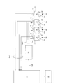
- FIG. 1 is a schematic configuration diagram illustrating a knock determination device and a knock control device for an internal combustion engine according to the present embodiment.
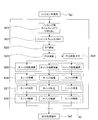
- 2 is a block diagram illustrating knocking determination and control in the knocking determination device and knocking control device of the internal combustion engine illustrated in FIG. 1, and
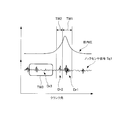
- FIG. 3 illustrates a time window in the block diagram illustrated in FIG. It is a figure to do.
- the internal combustion engine has at least one cylinder 10 as shown in FIG. 1 (in FIG. 1, four cylinders 10 are shown as an example). And an ECU (Electronics Control Unit) 20 that performs determination and control by arithmetic processing described later, and an ignition device 21 that controls a spark plug 14 described later based on a command from the ECU 20.
- the alarm device 22 will be described in a fourth embodiment described later.
- Each cylinder 10 includes a cylinder 11, a piston 12 that reciprocates within the cylinder 11, and a crank 13 that is coupled to the piston 12, and a crankshaft (not shown) is rotationally driven via the crank 13. Is done. Further, the cylinder 11 also has an air supply valve and an air supply port for supplying air together with fuel made of gas, gasoline, and the like, an exhaust valve and an exhaust port for exhausting the combusted fuel from the cylinder 11, but in FIG. The illustration is omitted.
- the fuel supplied to the cylinder 11 is ignited and burned using a spark plug 14 attached to the cylinder 11.
- a knock sensor 15 attached to the cylinder 11 a physical quantity correlated with the knocking intensity generated in each cylinder 10 is detected as the knock sensor signal Sg1.
- an acceleration sensor that detects acceleration is used as the knock sensor 15.
- an in-cylinder pressure sensor that detects in-cylinder pressure may be used. It can be implemented.
- the knock sensor signal Sg1 of each cylinder 10 detected by the knock sensor 15 is input to the ECU 20, and using the input knock sensor signal Sg1, calculation processing described later is performed to perform knocking determination. Then, the ECU 20 transmits an ignition timing command Sg2 for each cylinder 10 to the ignition device 21 based on the knocking determination by the arithmetic processing, and the ignition device 21 sends an ignition signal Sg3 to each cylinder 10 based on the ignition timing command Sg2. Is sending.
- Each cylinder 10 shown in FIG. 1 is also provided with a crank angle sensor for detecting the crank angle of the crankshaft, and a signal from this sensor is also input to the ECU 20 and used for arithmetic processing described later. Yes.
- the internal combustion engine shown in FIG. 1 may be another internal combustion engine as long as it has a similar function.
- a gas engine, a gasoline engine, a diesel engine, or the like may be used.
- Block B1 When the knock sensor signal Sg1 of each cylinder 10 detected by the knock sensor 15 is input to the ECU 20, the knock sensor signal Sg1 is knocked using the knocking time window TW1 (see FIG. 3) in the time zone where knocking occurs. Cut out the data.
- the knocking time window TW1 a crank angle range may be defined in advance.
- the knocking time window TW1 is from the crank angle after ignition and before the peak of the in-cylinder pressure to the crank angle at which combustion ends.
- Block B2 The extracted knocking data is passed through a BPF that allows only the knocking frequency component to pass, and a waveform signal having a knocking frequency (for example, about 3 kHz) is extracted.
- a knocking frequency for example, about 3 kHz
- Block B3 A calculation process of the waveform signal of the extracted knocking frequency is performed to obtain a first calculation value. For example, calculation processing for obtaining an integral value of the absolute value of the waveform signal and obtaining a value equivalent to POA is performed. Instead of this arithmetic processing, arithmetic processing for obtaining the maximum value of amplitude may be performed, or arithmetic processing for obtaining POA by performing FFT analysis may be performed.
- the integral value and the POA are mathematically equivalent.
- the power spectrum is calculated by the FFT analysis, the power spectrum density is calculated based on the calculated power spectrum, and the sum of squares of the power spectrum density near the knocking frequency is calculated. Thus, what is necessary is just to obtain
- Block B4 Similarly to the block B1 described above, reference data is cut out from the knock sensor signal Sg1 using the reference time window.
- reference time window and reference data will be described with reference to FIG.
- reference data data Dr1 when knocking has not occurred, data Dr2 at the early stage of combustion, or background data Dr3 when no ignition is performed can be used.
- FIG. 3 the in-cylinder pressure of the cylinder 11 is also shown for reference.
- the same time window as the knocking time window TW1 for detecting knocking is used, data below a prescribed value defined in advance is held, and this is used as reference data To do.
- the data to be held is sequentially updated and used as reference data.
- Block B5 As in the above-described block B2, the cut-out reference data is passed through a BPF that allows only the reference frequency component to pass, and a waveform signal of the reference frequency is extracted.
- a BPF that allows only a component having the same frequency as the knocking detection frequency (for example, about 3 kHz) may be used.
- the reference BPF is also different, and only the frequency component (for example, about 1 kHz) different from the knocking detection frequency is used. It is sufficient to use a BPF that passes through.
- the extracted reference frequency waveform signal is calculated to obtain a second calculation value, for example, the integral value or maximum amplitude value or POA of the absolute value of the waveform signal of the reference frequency. .
- Block B7 An average process of the second calculation values obtained by the calculation process of the block B6 is performed to obtain a reference average value.
- the reference average value may be obtained by moving average processing using the second calculated values of the most recent cycles, but for example, after passing through a low-pass filter for removing the upper limit value and the lower limit value.
- the reference average value may be obtained, or the standard deviation ( ⁇ ) of the second computed value in a plurality of cycles is obtained, and the reference average value is obtained for the second computed value within the obtained 1 ⁇ range. May be. It is necessary to determine the upper limit value and the lower limit value in advance, but when using the second calculation value within the range of 1 ⁇ , it is not necessary to determine the upper limit value and the lower limit value. Even if there is, the reference average value can be obtained by following the change with time.
- Block B8 The S / N ratio of the first calculation value is obtained by dividing the first calculation value obtained by the calculation process of the block B3 by the reference average value obtained by the average process of the block B7. Thereby, the individual difference of the sensor sensitivity of the knock sensor 15 can be corrected.
- Block B9 The relationship between the S / N ratio and the weighting factor is defined in advance, and the S / N ratio obtained in block B8 is weighted. That is, a multiplication value obtained by multiplying the obtained S / N ratio by the corresponding weight coefficient is obtained.
- the weighting coefficient is a coefficient that makes the calculated S / N ratio a numerical value that includes the knocking strength and the knocking frequency.
- the knocking determination can be performed only by evaluating one numerical value in one cycle. . Conventionally, knocking determination is performed from knocking strength and knocking frequency, and a predetermined number of cycles are necessary for the determination. However, by performing the above-described weighting, large knocking can be detected quickly and easily. it can.
- the relationship between the S / N ratio and the weighting factor is actually defined as map data by performing a test operation of the internal combustion engine. At this time, the relationship between the knocking severity indicating the damage to the internal combustion engine (for example, damage due to liner temperature, damage to the piston ring, gasket, etc.) and the advance of the ignition timing is set to be equal to S.
- the relationship between the / N ratio and the weighting factor is defined. For example, on the basis of the maximum S / N ratio that damages the engine after only one occurrence, a curve as shown in block B9 (for example, an nth-order curve), that is, as the S / N ratio increases.
- the relationship between the S / N ratio and the weighting factor is defined so that the weighting factor becomes larger.
- Block B10 A moving average value is obtained for the S / N ratio (multiplication value) weighted in block B9. For example, the moving average value for the most recent weighted S / N ratios is obtained.
- the moving average value obtained in block B10 is the knock index.
- Knocking determination is performed on the knock index in block B11 based on a predetermined knock determination threshold.
- the knock determination threshold varies depending on the specifications of the internal combustion engine, and is set according to the specifications, but is, for example, 20 to 50%.
- Block B13 Control is performed based on the knocking determination in block B13. For example, depending on the magnitude of the knock index, ignition timing command Sg2 is ignited that delays ignition timing by a small amount, delays it greatly (retards), lowers the output, or trips (stops) the engine. Transmit to device 21.
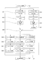
- FIG. 4 is a block diagram illustrating knock determination and control in the knock determination device and the knock control device of the internal combustion engine of the present embodiment.
- the knocking determination and control of the present embodiment will be described.
- the knocking determination device and the knocking control device for the internal combustion engine shown in FIG. 1 perform the knocking determination and control described below, but other devices can be used as long as they have the same functions. But it ’s okay. Further, the following knocking determination and control are performed for each cylinder and each cycle.
- knocking data is extracted from the knock sensor signal Sg1 using the knocking time window TW1 in the time zone where knocking occurs.
- the knocking time window TW1 may be the one described in the first embodiment (see FIG. 3).
- the extracted knocking data is passed through a BPF that allows only the knocking frequency component to pass, and a waveform signal having a knocking frequency (for example, about 3 kHz) is extracted.
- a knocking frequency for example, about 3 kHz
- each knock index that is, a large knock index, a medium knock index, and a small knock index is calculated using the following Equation 1 and Table 1.
- C1 is the number of cycles exceeding the threshold Th for a predefined POA
- C2 is the number of specified cycles
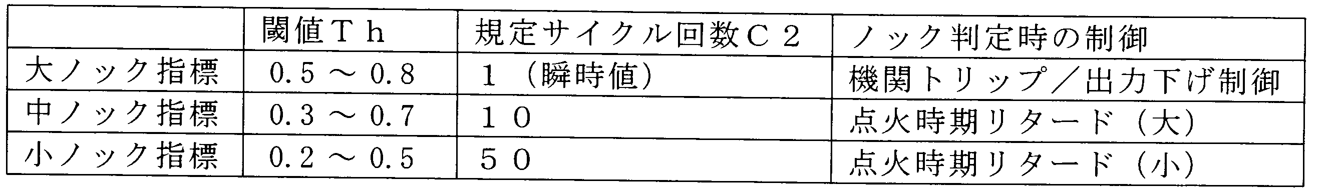
- a plurality of sets of thresholds Th for the large knock index, medium knock index, and small knock index and the number of specified cycles C2 corresponding to the threshold Th are defined.
- the threshold value Th and the specified cycle number C2 shown in Table 1 are examples, and can be changed as appropriate according to the characteristics of the internal combustion engine. However, the higher the threshold value Th, the smaller the specified cycle number C2. .
- the calculated large knock index, medium knock index, and small knock index are determined based on knock determination thresholds for the predetermined large knock index, medium knock index, and small knock index, and control is performed based on the determination. For example, in the case of a small knock determination, the ignition timing is delayed by a small amount, in the case of a medium knock determination, the ignition timing is greatly delayed (retarded), and in the case of a large knock determination, the output is reduced, or the engine
- the ignition timing command Sg2 for tripping (stopping) is transmitted to the ignition device 21.
- the knock determination threshold varies depending on the specifications of the internal combustion engine, and is set according to the specifications, but is, for example, 20 to 50%.
- Block B29 A moving average is obtained for the POA calculated in block B24. For example, a moving average is calculated for a plurality of recent POAs. By obtaining the POA moving average, the tendency of knocking can be grasped.
- the POA is divided into a large knock index, a medium knock index, and a small knock index, and when calculating each knock index, the number of cycles is changed for each knock index, so that the detection speed for each knock index is changed.
- the depth can be changed, so that a larger knock can be detected more quickly.
- FIG. 5 is a block diagram illustrating knocking determination and control in the knocking determination device and knocking control device for the internal combustion engine of the present embodiment.
- the knocking determination and control of the present embodiment will be described.
- the knocking determination device and the knocking control device for the internal combustion engine shown in FIG. 1 perform the knocking determination and control described below. But it ’s okay. Further, the following knocking determination and control are performed for each cylinder and each cycle.
- knocking data is extracted from the knock sensor signal Sg1 using the knocking time window TW1 in the time zone where knocking occurs.
- the knocking time window TW1 may be the one described in the first embodiment (see FIG. 3).
- the extracted knocking data is passed through a BPF that allows only the knocking frequency component to pass, and a waveform signal having a knocking frequency (for example, about 3 kHz) is extracted.
- the knocking BPF may be the same as that described in the first embodiment.
- Block B33 A calculation process of the waveform signal of the extracted knocking frequency is performed to obtain a first calculation value. For example, calculation processing for obtaining an integral value of the absolute value of the waveform signal and obtaining a value equivalent to POA is performed. Instead of this arithmetic processing, arithmetic processing for obtaining the maximum value of amplitude may be performed, or arithmetic processing for obtaining POA by performing FFT analysis may be performed.
- the integral value and the POA are mathematically equivalent.
- reference data is cut out from the knock sensor signal Sg1 using a reference time window.
- the reference time window and reference data may also be those described in the first embodiment (see FIG. 3).
- Block B35 Similarly to the block B32 described above, the cut-out reference data is passed through a BPF that allows only the reference frequency component to pass, and a waveform signal of the reference frequency is extracted.
- the reference BPF may also be the one described in the first embodiment.
- the extracted reference frequency waveform signal is calculated to obtain a second calculated value, for example, the integral value or the maximum amplitude value or POA of the absolute value of the waveform signal of the reference frequency. .
- Block B37 An average process of the second calculation values obtained by the calculation process of the block B36 is performed to obtain a reference average value.
- the reference average value may be obtained.
- Block B38 The S / N ratio of the first calculation value is obtained by dividing the first calculation value obtained by the calculation process of the block B33 by the reference average value obtained by the average process of the block B37. Thereby, the individual difference of the sensor sensitivity of the knock sensor 15 can be corrected.
- Each knock index that is, a large knock index, a medium knock index, and a small knock index is calculated with respect to the S / N ratio that has been subjected to the calculation processing, using Equation 1 and Table 1 above.
- the threshold value Th in Table 1 may be defined with respect to the S / N ratio.
- the calculated large knock index, medium knock index, and small knock index are determined based on knock determination thresholds for the predetermined large knock index, medium knock index, and small knock index, and control is performed based on the determination. For example, in the case of a small knock determination, the ignition timing is delayed by a small amount, in the case of a medium knock determination, the ignition timing is greatly delayed (retarded), and in the case of a large knock determination, the output is reduced, or the engine
- the ignition timing command Sg2 for tripping (stopping) is transmitted to the ignition device 21.
- the knock determination threshold varies depending on the specifications of the internal combustion engine, and is set according to the specifications, but is, for example, 20 to 50%.
- the speed of detection can be changed for each knock index by changing the prescribed number of cycles for each knock index.
- the larger the knock the faster it can be detected.
- Example 4 A knock determination device and a knock control device for an internal combustion engine according to this embodiment will be described with reference to FIG.
- the knocking determination device and the knocking control device for the internal combustion engine shown in FIG. 1 are illustrated, but other devices may be used as long as they have equivalent functions.
- the present embodiment further includes an alarm device 22 that issues and transmits an alarm based on a command from the ECU 20.
- the ECU 20 holds data of the initial stage of shipment of the internal combustion engine in advance for the second calculated value (the integrated value of the absolute value of the waveform signal of the reference frequency or the maximum value of the amplitude or POA) described in the first embodiment. This is set as a reference value. And if the 2nd calculated value of the arbitrary cylinders 10 acquired after that falls below a standard threshold defined beforehand with respect to a standard value, it will judge with a sensitivity fall by a secular change.
- the second calculation value of all the cylinders 10 may be averaged and used as a reference value. Also in this case, if the second calculated value of the arbitrary cylinder 10 acquired thereafter falls below the reference threshold value defined in advance with respect to the reference value, it is determined that the sensitivity is decreased due to secular change.
- two types of deterioration of the knock sensor 15 and deterioration of the cable can be detected as the secular change.
- the ECU 20 uses the alarm device 22 to notify the operator of the detection result of the decrease in sensitivity due to the secular change or to transmit to the remote monitoring device, thereby notifying the secular change and its precursor. ing.
- the present invention is applicable to internal combustion engines such as gas engines and gasoline engines.
Landscapes
- Engineering & Computer Science (AREA)
- Chemical & Material Sciences (AREA)
- Combustion & Propulsion (AREA)
- Mechanical Engineering (AREA)
- General Engineering & Computer Science (AREA)
- Signal Processing (AREA)
- Physics & Mathematics (AREA)
- General Physics & Mathematics (AREA)
- Computer Hardware Design (AREA)
- Microelectronics & Electronic Packaging (AREA)
- Combined Controls Of Internal Combustion Engines (AREA)
- Electrical Control Of Ignition Timing (AREA)
Abstract
大きなノッキングを早く検知することができ、ノッキング判定が容易な内燃機関のノッキング判定装置及びノッキング制御装置を提供する。そのため、ノッキング用タイムウィンドウ及びBPF(B1~B2)を用いて、ノックセンサ信号(Sg1)からノッキング周波数の波形信号を取り出し、積分して第1の演算値を求め(B3)、リファレンス用タイムウィンドウ及びBPF(B4~B5)を用いて、ノックセンサ信号(Sg1)からリファレンス周波数の波形信号を取り出し、積分して第2の演算値を求め(B6)、第2の演算値の複数個の平均値を求め(B7)、第1の演算値を平均値で除算したS/N比を求め(B8)、S/N比に重み係数を乗算した乗算値を求め(B9)、乗算値の複数個の移動平均値を求め(B10)、移動平均値をノック指標として用いて、ノッキングの判定、制御を行う(B11~B13)。
Description
本発明は、ガスエンジンやガソリンエンジン等におけるノッキング判定及び制御を行う内燃機関のノッキング判定装置及びノッキング制御装置に関する。
ガスエンジンやガソリンエンジン等の内燃機関では、筒内で燃料が異常燃焼するノッキングが生じる。ノッキングの強度が大きいと、エンジンが損傷するおそれがある。そこで、これらのエンジンでは、ノッキングを検知し、ノッキング強度に応じて点火時期の制御や出力を下げる制御を行っている。
ノッキング判定には、筒内圧センサを使用する場合と、例えば、加速度センサ等を使用する場合がある。ノッキング判定では、一般的に下記の手法が用いられている。
(1)センサ信号から、ノッキングが起こる時間帯(タイムウィンドウ)のデータを取り出す。
(2)ノッキング周波数の成分のみ通過させるバンドパスフィルタ(以下、BPF)にセンサ信号を通し、ノッキング周波数の波形信号を取り出す。
(3)取り出した波形信号の演算処理を行い、ノッキング強度を求める。例えば、振幅の最大値を求める演算処理をしたり、高速フーリエ変換解析(以下、FFT解析)を行い、ノッキング周波数付近のパワースペクトル密度の平方和であるパーシャルオーバーオール(以下、POA)を求める演算処理をしたり、波形信号を積分し、POA相当の値を求める演算処理をしたりして、ノッキング強度を求めている。
(4)これらの演算を各サイクルで行い、各サイクルで演算したノッキング強度について、所定回数のサイクル(例えば、50サイクル)での頻度も考慮したノック指標を求めて、ノッキング判定を行う。
ノッキングは、各サイクルで連続して同じ強度となるわけではない。ノッキングが発生し易い状態では、上記ノック指標の平均値が上がると共に、ノック指標が大きい頻度が高くなる傾向がある。又、ノッキング強度が大きい場合、エンジンの損傷防止のため、早い検知性能が求められる。
従って、エンジンの損傷を防ぎ、一定のノッキングレベルを維持する制御を行うには、下記について考慮して、ノッキング判定することが必要である。
(a)ノッキング強度とノッキング頻度の2つの情報からノッキング判定を行う。
(b)ノッキング強度が大きい場合、エンジンの損傷防止のため、早く(例えば、1サイクルで)検知する。
(a)ノッキング強度とノッキング頻度の2つの情報からノッキング判定を行う。
(b)ノッキング強度が大きい場合、エンジンの損傷防止のため、早く(例えば、1サイクルで)検知する。
ところが、従来のノッキング検知では、ノッキング強度だけでなく、ノッキング頻度をカウントする必要があり、所定回数のサイクルが必要となり、大きいノッキングの早い検知ができなかったり(例えば、特許文献1の段落0041参照)、ノック指標の演算(例えば、特許文献2の図8、図9参照;特に、ノック判定値Vkdlを求めるためのu値の演算)が複雑であったりして、大きいノッキングを早く、容易に検知することができないという問題があった。
本発明は上記課題に鑑みなされたもので、大きなノッキングを早く検知することができ、ノッキング判定が容易な内燃機関のノッキング判定装置及びノッキング制御装置を提供することを目的とする。
上記課題を解決する第1の発明に係る内燃機関のノッキング判定装置は、
内燃機関の各気筒に取り付けられ、ノッキングの強度に相関する加速度又は筒内圧を測定する加速度センサ又は筒内圧センサと、
前記加速度センサ又は前記筒内圧センサで測定されたセンサ信号に基づいて、ノッキングの判定及び制御を行う制御手段とを備え、
前記制御手段は、
前記センサ信号からノッキング周波数の波形信号を取り出し、前記ノッキング周波数の波形信号による第1の演算値を演算し、
前記センサ信号からリファレンス周波数の波形信号を取り出し、前記リファレンス周波数の波形信号による第2の演算値を演算し、前記第2の演算値の複数個の平均値を求め、
前記第1の演算値を前記平均値で除算した比を求め、
前記比をノッキング強度とノッキング頻度とを含むノック指標に変換し、
前記ノック指標の大きさに基づいて、ノッキングの判定を行う
ことを特徴とする。
上記課題を解決する第2の発明に係る内燃機関のノッキング判定装置は、
上記第1の発明に記載の内燃機関のノッキング判定装置において、
前記制御手段は、
前記比を前記ノック指標に変換する重み係数を予め規定しておき、前記比に前記重み係数を乗算した乗算値を求め、前記乗算値の複数個の移動平均値を求め、前記移動平均値をノッキングの判定を行う前記ノック指標として用いる
ことを特徴とする。
上記第1の発明に記載の内燃機関のノッキング判定装置において、
前記制御手段は、
前記比を前記ノック指標に変換する重み係数を予め規定しておき、前記比に前記重み係数を乗算した乗算値を求め、前記乗算値の複数個の移動平均値を求め、前記移動平均値をノッキングの判定を行う前記ノック指標として用いる
ことを特徴とする。
上記課題を解決する第3の発明に係る内燃機関のノッキング判定装置は、
上記第2の発明に記載の内燃機関のノッキング判定装置において、
前記制御手段は、
前記比が大きくなるほど前記重み係数を大きくする
ことを特徴とする。
上記第2の発明に記載の内燃機関のノッキング判定装置において、
前記制御手段は、
前記比が大きくなるほど前記重み係数を大きくする
ことを特徴とする。
上記課題を解決する第4の発明に係る内燃機関のノッキング判定装置は、
上記第1の発明に記載の内燃機関のノッキング判定装置において、
前記制御手段は、
前記比に対する閾値と当該閾値に応じた規定回数を予め規定しておき、前記比が前記閾値を超えた回数を前記規定回数で除算した百分率を求め、前記百分率をノッキングの判定を行う前記ノック指標として用いる
ことを特徴とする。
上記第1の発明に記載の内燃機関のノッキング判定装置において、
前記制御手段は、
前記比に対する閾値と当該閾値に応じた規定回数を予め規定しておき、前記比が前記閾値を超えた回数を前記規定回数で除算した百分率を求め、前記百分率をノッキングの判定を行う前記ノック指標として用いる
ことを特徴とする。
上記課題を解決する第5の発明に係る内燃機関のノッキング判定装置は、
上記第4の発明に記載の内燃機関のノッキング判定装置において、
前記制御手段は、
各々異なる前記閾値と各々の前記閾値に応じた前記規定回数の組を複数組規定し、前記閾値が大きくなるほど前記規定回数を小さくする
ことを特徴とする。
上記第4の発明に記載の内燃機関のノッキング判定装置において、
前記制御手段は、
各々異なる前記閾値と各々の前記閾値に応じた前記規定回数の組を複数組規定し、前記閾値が大きくなるほど前記規定回数を小さくする
ことを特徴とする。
上記課題を解決する第6の発明に係る内燃機関のノッキング判定装置は、
上記第1~第5のいずれか1つの発明に記載の内燃機関のノッキング判定装置において、
前記制御手段は、
前記センサ信号の同じ時間帯から前記ノッキング周波数の波形信号と前記リファレンス周波数の波形信号を取り出すと共に、予め規定した規定値以下のものを前記リファレンス周波数の波形信号とする
ことを特徴とする。
上記第1~第5のいずれか1つの発明に記載の内燃機関のノッキング判定装置において、
前記制御手段は、
前記センサ信号の同じ時間帯から前記ノッキング周波数の波形信号と前記リファレンス周波数の波形信号を取り出すと共に、予め規定した規定値以下のものを前記リファレンス周波数の波形信号とする
ことを特徴とする。
上記課題を解決する第7の発明に係る内燃機関のノッキング判定装置は、
上記第1~第5のいずれか1つの発明に記載の内燃機関のノッキング判定装置において、
前記制御手段は、
前記センサ信号の異なる時間帯から前記ノッキング周波数の波形信号と前記リファレンス周波数の波形信号を取り出すと共に、前記リファレンス周波数の波形信号の前記時間帯を、前記ノッキング周波数の波形信号の前記時間帯の直前の時間帯、又は、未点火時の時間帯とする
ことを特徴とする。
上記第1~第5のいずれか1つの発明に記載の内燃機関のノッキング判定装置において、
前記制御手段は、
前記センサ信号の異なる時間帯から前記ノッキング周波数の波形信号と前記リファレンス周波数の波形信号を取り出すと共に、前記リファレンス周波数の波形信号の前記時間帯を、前記ノッキング周波数の波形信号の前記時間帯の直前の時間帯、又は、未点火時の時間帯とする
ことを特徴とする。
上記課題を解決する第8の発明に係る内燃機関のノッキング判定装置は、
上記第1~7のいずれか1つの発明に記載の内燃機関のノッキング判定装置において、
前記制御手段は、
複数個の前記第2の演算値の標準偏差を求め、当該標準偏差の範囲内にある前記第2の演算値を用いて前記平均値を求める
ことを特徴とする。
上記第1~7のいずれか1つの発明に記載の内燃機関のノッキング判定装置において、
前記制御手段は、
複数個の前記第2の演算値の標準偏差を求め、当該標準偏差の範囲内にある前記第2の演算値を用いて前記平均値を求める
ことを特徴とする。
上記課題を解決する第9の発明に係る内燃機関のノッキング判定装置は、
上記第1~第8のいずれか1つの発明に記載の内燃機関のノッキング判定装置において、
前記制御手段は、
前記内燃機関の初期の前記第2の演算値を基準値として保持しておくと共に、当該基準値に対する基準閾値を規定しておき、
新たに演算した前記第2の演算値が前記基準値に対し前記基準閾値より下がった場合、前記加速度センサ又は前記筒内圧センサの感度低下と判定して、通知を行う
ことを特徴とする。
上記第1~第8のいずれか1つの発明に記載の内燃機関のノッキング判定装置において、
前記制御手段は、
前記内燃機関の初期の前記第2の演算値を基準値として保持しておくと共に、当該基準値に対する基準閾値を規定しておき、
新たに演算した前記第2の演算値が前記基準値に対し前記基準閾値より下がった場合、前記加速度センサ又は前記筒内圧センサの感度低下と判定して、通知を行う
ことを特徴とする。
上記課題を解決する第10の発明に係る内燃機関のノッキング判定装置は、
上記第1~第8のいずれか1つの発明に記載の内燃機関のノッキング判定装置において、
前記制御手段は、
全ての前記気筒の前記第2の演算値の平均を基準値として保持しておくと共に、当該基準値に対する基準閾値を規定しておき、
新たに演算した前記第2の演算値が前記基準値に対し前記基準閾値より下がった場合、前記加速度センサ又は前記筒内圧センサの感度低下と判定して、通知を行う
ことを特徴とする。
上記第1~第8のいずれか1つの発明に記載の内燃機関のノッキング判定装置において、
前記制御手段は、
全ての前記気筒の前記第2の演算値の平均を基準値として保持しておくと共に、当該基準値に対する基準閾値を規定しておき、
新たに演算した前記第2の演算値が前記基準値に対し前記基準閾値より下がった場合、前記加速度センサ又は前記筒内圧センサの感度低下と判定して、通知を行う
ことを特徴とする。
上記課題を解決する第11の発明に係る内燃機関のノッキング制御装置は、
上記第1~第10のいずれか1つの発明に記載の内燃機関のノッキング判定装置を用いた内燃機関のノッキング制御装置であって、
前記制御手段は、
ノッキングの判定に応じて、前記気筒の点火時期の遅角化、前記内燃機関の出力の低下又は停止を行う
ことを特徴とする。
上記第1~第10のいずれか1つの発明に記載の内燃機関のノッキング判定装置を用いた内燃機関のノッキング制御装置であって、
前記制御手段は、
ノッキングの判定に応じて、前記気筒の点火時期の遅角化、前記内燃機関の出力の低下又は停止を行う
ことを特徴とする。
本発明によれば、ノッキング強度とノッキング頻度とを含むノック指標を用いるので、ノッキングを容易に判定することができ、大きいノッキングほど早く検知することができる。又、経年変化による感度低下も検知することができる。
以下、本発明に係る内燃機関のノッキング判定装置及びノッキング制御装置の実施形態について、図1~図5を参照して説明する。
(実施例1)
図1は、本実施例の内燃機関のノッキング判定装置及びノッキング制御装置を説明する概略構成図である。又、図2は、図1に示した内燃機関のノッキング判定装置及びノッキング制御装置におけるノッキング判定及び制御を説明するブロック図であり、図3は、図2に示したブロック図におけるタイムウィンドウを説明する図である。
図1は、本実施例の内燃機関のノッキング判定装置及びノッキング制御装置を説明する概略構成図である。又、図2は、図1に示した内燃機関のノッキング判定装置及びノッキング制御装置におけるノッキング判定及び制御を説明するブロック図であり、図3は、図2に示したブロック図におけるタイムウィンドウを説明する図である。
本実施例の内燃機関のノッキング判定装置及びノッキング制御装置において、内燃機関(エンジン)は、図1に示すように、少なくとも1つの気筒10(図1では、一例として、4つの気筒10を図示)と、後述する演算処理による判定や制御を行うECU(Electronics Control Unit)20と、ECU20からの指令に基づいて、後述する点火プラグ14を制御する点火装置21とを有している。なお、警報装置22については、後述の実施例4において説明する。
各気筒10は、シリンダ11と、シリンダ11内を往復運動するピストン12と、ピストン12に連結されたクランク13とを有しており、クランク13を介して、クランク軸(図示省略)が回転駆動される。又、シリンダ11にガスやガソリン等からなる燃料と共に空気を供給する給気弁及び給気ポート、燃焼した燃料をシリンダ11から排気する排気弁及び排気ポート等も有しているが、図1では、図示を省略している。
シリンダ11に供給された燃料は、シリンダ11に取り付けた点火プラグ14を用いて点火し、燃焼させる。このとき、シリンダ11に取り付けたノックセンサ15を用いて、各気筒10に発生するノッキング強度に相関する物理量を、ノックセンサ信号Sg1として検出している。本実施例では、ノックセンサ15として、加速度を検出する加速度センサを用いるが、これに代えて、筒内圧を検出する筒内圧センサを用いても、本実施例及び後述する実施例2~4を実施可能である。
ノックセンサ15で検出された各気筒10のノックセンサ信号Sg1は、ECU20へ入力され、入力されたノックセンサ信号Sg1を用い、後述する演算処理を行って、ノッキング判定を行っている。そして、ECU20は、演算処理によるノッキング判定に基づいて、各気筒10に対する点火時期指令Sg2を点火装置21へ送信し、点火装置21は、点火時期指令Sg2に基づいて、各気筒10へ点火信号Sg3を送信している。
なお、図1に示した各気筒10においては、クランク軸のクランク角を検出するクランク角センサも設けられており、このセンサからの信号もECU20へ入力されて、後述する演算処理に用いられている。
又、図1に示した内燃機関は、同等の機能を有する構成であれば、他の内燃機関でも良い。例えば、ガスエンジン、ガソリンエンジン、ディーゼルエンジン等でも良い。
次に、図2、図3を参照して、図1に示した内燃機関のノッキング判定装置及びノッキング制御装置におけるノッキング判定及び制御を説明する。なお、以下のノッキング判定及び制御は、各気筒、各サイクルで各々行っている。
(ブロックB1)
ノックセンサ15で検出された各気筒10のノックセンサ信号Sg1が、ECU20へ入力されると、ノッキングが起こる時間帯のノッキング用タイムウィンドウTW1(図3参照)を用いて、ノックセンサ信号Sg1からノッキング用データを切り出す。ノッキング用タイムウィンドウTW1としては、クランク角の範囲を予め規定しておけば良い。ここでは、一例として、点火後であって、筒内圧のピークより前のクランク角から、燃焼が終了するクランク角までを、ノッキング用タイムウィンドウTW1としている。
ノックセンサ15で検出された各気筒10のノックセンサ信号Sg1が、ECU20へ入力されると、ノッキングが起こる時間帯のノッキング用タイムウィンドウTW1(図3参照)を用いて、ノックセンサ信号Sg1からノッキング用データを切り出す。ノッキング用タイムウィンドウTW1としては、クランク角の範囲を予め規定しておけば良い。ここでは、一例として、点火後であって、筒内圧のピークより前のクランク角から、燃焼が終了するクランク角までを、ノッキング用タイムウィンドウTW1としている。
(ブロックB2)
切り出したノッキング用データを、ノッキング周波数の成分のみを通過させるBPFに通し、ノッキング周波数(例えば、3kHz程度)の波形信号を取り出す。
切り出したノッキング用データを、ノッキング周波数の成分のみを通過させるBPFに通し、ノッキング周波数(例えば、3kHz程度)の波形信号を取り出す。
(ブロックB3)
取り出したノッキング周波数の波形信号の演算処理を行い、第1の演算値を求める。例えば、波形信号の絶対値の積分値を求め、POA相当の値を求める演算処理を行う。なお、この演算処理に代えて、振幅の最大値を求める演算処理をしたり、又は、FFT解析を行い、POAを求める演算処理をしたりしても良い。なお、上記積分値とPOAは数学的に等価である。
取り出したノッキング周波数の波形信号の演算処理を行い、第1の演算値を求める。例えば、波形信号の絶対値の積分値を求め、POA相当の値を求める演算処理を行う。なお、この演算処理に代えて、振幅の最大値を求める演算処理をしたり、又は、FFT解析を行い、POAを求める演算処理をしたりしても良い。なお、上記積分値とPOAは数学的に等価である。
FFT解析を行い、POAを求める場合には、FFT解析により、パワースペクトルを算出し、算出したパワースペクトルに基づいて、パワースペクトル密度を算出し、ノッキング周波数付近のパワースペクトル密度の平方和を算出することで、POAを求めれば良い。
(ブロックB4)
上述したブロックB1と同じように、リファレンス用タイムウィンドウを用いて、ノックセンサ信号Sg1からリファレンス用データを切り出す。
上述したブロックB1と同じように、リファレンス用タイムウィンドウを用いて、ノックセンサ信号Sg1からリファレンス用データを切り出す。
ここで、リファレンス用タイムウィンドウ及びファレンス用データについて、図3を参照して説明を行う。リファレンス用データとしては、ノッキング未発生時のデータDr1、燃焼初期段階のデータDr2又は未点火時のバックグラウンドのデータDr3を用いることができる。なお、図3では、参考のため、シリンダ11の筒内圧も併記している。
ノッキング未発生時のデータDr1を用いる場合には、ノッキングを検知するノッキング用タイムウィンドウTW1と同じタイムウィンドウを用い、予め規定した規定値以下のデータを保持しておき、これをリファレンス用データとして使用する。規定値以下のデータが新たに取得できた場合には、保持するデータを逐次更新していき、これをリファレンス用データとして使用する。
又、燃焼初期段階のデータDr2を用いる場合には、タイムウィンドウTW1とは異なり、タイムウィンドウTW1の直前のタイムウィンドウTW2のデータを使用する。又、未点火時のバックグラウンドのデータDr3を用いる場合にも、タイムウィンドウTW1とは異なり、未点火時のタイムウィンドウTW3のデータを使用する。
(ブロックB5)
上述したブロックB2と同じように、切り出したリファレンス用データを、リファレンス周波数の成分のみを通過させるBPFに通し、リファレンス周波数の波形信号を取り出す。
上述したブロックB2と同じように、切り出したリファレンス用データを、リファレンス周波数の成分のみを通過させるBPFに通し、リファレンス周波数の波形信号を取り出す。
ここで、リファレンス用データとノッキング用データのタイムウィンドウが同じタイムウィンドウTW1を用いる場合は、ノッキング検知の周波数と同じ周波数の成分(例えば、3kHz程度)のみを通過させるBPFを用いれば良い。一方、リファレンス用データとノッキング用データのタイムウィンドウが異なり、タイムウィンドウTW2又はTW3を用いる場合は、リファレンス用のBPFも異なるものとし、ノッキング検知の周波数と異なる周波数の成分(例えば、1kHz程度)のみを通過させるBPFを用いれば良い。
(ブロックB6)
上述したブロックB3と同じように、取り出したリファレンス周波数の波形信号の演算処理を行い、第2の演算値、例えば、リファレンス周波数の波形信号の絶対値の積分値又は振幅の最大値又はPOAを求める。
上述したブロックB3と同じように、取り出したリファレンス周波数の波形信号の演算処理を行い、第2の演算値、例えば、リファレンス周波数の波形信号の絶対値の積分値又は振幅の最大値又はPOAを求める。
(ブロックB7)
ブロックB6の演算処理により求めた第2の演算値の平均処理を行い、リファレンス平均値を求める。
ブロックB6の演算処理により求めた第2の演算値の平均処理を行い、リファレンス平均値を求める。
この際、直近の複数回のサイクルの第2の演算値を用いた移動平均処理により、リファレンス平均値を求めても良いが、例えば、上限値と下限値を除くためのローパスフィルタを通した後に、リファレンス平均値を求めても良いし、複数回のサイクルの第2の演算値の標準偏差(σ)を求め、求めた1σの範囲内にある第2の演算値について、リファレンス平均値を求めても良い。予め、上限値と下限値を決めておく必要があるが、1σの範囲内にある第2の演算値を用いる場合には、上限値と下限値を決めておく必要はなく、例えば、経時変化があっても、その経時変化に追従して、リファレンス平均値を求めることができる。
(ブロックB8)
ブロックB3の演算処理により求めた第1の演算値を、ブロックB7の平均処理により求めたリファレンス平均値で除算して、第1の演算値のS/N比を求める。これにより、ノックセンサ15のセンサ感度の個体差を補正することができる。
ブロックB3の演算処理により求めた第1の演算値を、ブロックB7の平均処理により求めたリファレンス平均値で除算して、第1の演算値のS/N比を求める。これにより、ノックセンサ15のセンサ感度の個体差を補正することができる。
(ブロックB9)
予め、S/N比と重み係数との関係を規定しておき、ブロックB8で求めたS/N比に対して重み付けを行う。つまり、求めたS/N比に、対応する重み係数を乗算した乗算値を求める。この重み係数とは、求めたS/N比に対して、ノッキング強度と共にノッキング頻度を含む数値とする係数であり、これにより、1つの数値を1サイクルで評価するだけでノッキング判定が可能となる。従来は、ノッキング強度とノッキング頻度からノッキング判定を行っており、判定のために所定回数のサイクルが必要であったが、上述した重み付けを行うことにより、大きいノッキングを早く、容易に検知することができる。
予め、S/N比と重み係数との関係を規定しておき、ブロックB8で求めたS/N比に対して重み付けを行う。つまり、求めたS/N比に、対応する重み係数を乗算した乗算値を求める。この重み係数とは、求めたS/N比に対して、ノッキング強度と共にノッキング頻度を含む数値とする係数であり、これにより、1つの数値を1サイクルで評価するだけでノッキング判定が可能となる。従来は、ノッキング強度とノッキング頻度からノッキング判定を行っており、判定のために所定回数のサイクルが必要であったが、上述した重み付けを行うことにより、大きいノッキングを早く、容易に検知することができる。
S/N比と重み係数との関係は、実際は、内燃機関の試験運転を行って、マップデータとして規定している。この際、内燃機関へのダメージ(例えば、ライナ温度によるダメージ、ピストンリング、ガスケットのダメージ等)を表すノッキング・シビアリティと点火時期の進角化との関係と同等の関係となるように、S/N比と重み係数との関係を規定している。例えば、1回発生しただけでエンジンが損傷する最大のS/N比を基準に、ブロックB9に示すような曲線(例えば、n次曲線)となるように、つまり、S/N比が大きくなるほど、重み係数がより大きくなるように、S/N比と重み係数との関係を規定している。
(ブロックB10)
ブロックB9で重み付けしたS/N比(乗算値)について、移動平均値を求める。例えば、直近の複数個の重み付けしたS/N比についての移動平均値を求める。
ブロックB9で重み付けしたS/N比(乗算値)について、移動平均値を求める。例えば、直近の複数個の重み付けしたS/N比についての移動平均値を求める。
(ブロックB11)
本実施例では、ブロックB10で求めた移動平均値がノック指標となる。
本実施例では、ブロックB10で求めた移動平均値がノック指標となる。
(ブロックB12)
ブロックB11におけるノック指標を、予め規定したノック判定閾値に基づいて、ノッキング判定を行う。なお、ノック判定閾値は、内燃機関の仕様により異なるので、その仕様に応じて設定されるが、例えば、20~50%である。
ブロックB11におけるノック指標を、予め規定したノック判定閾値に基づいて、ノッキング判定を行う。なお、ノック判定閾値は、内燃機関の仕様により異なるので、その仕様に応じて設定されるが、例えば、20~50%である。
(ブロックB13)
ブロックB13におけるノッキング判定に基づいて、制御を行う。例えば、ノック指標の大きさに応じて、点火時期を小さく遅らせたり、大きく遅らせたり(遅角化)、更には、出力を下げたり、機関をトリップ(停止)したりする点火時期指令Sg2を点火装置21へ送信する。
ブロックB13におけるノッキング判定に基づいて、制御を行う。例えば、ノック指標の大きさに応じて、点火時期を小さく遅らせたり、大きく遅らせたり(遅角化)、更には、出力を下げたり、機関をトリップ(停止)したりする点火時期指令Sg2を点火装置21へ送信する。
このように、重み付けを行なったノック指標を用いることで、ノッキング強度と共にノッキング頻度を含む数値とすることができ、小さいノッキングから大きいノッキングまで、1つのアナログ値で取り扱うことができる。これにより、ノッキング判定が容易になり、制御しやすくなると共に、大きなノッキングを早く検出することができる。
(実施例2)
図4は、本実施例の内燃機関のノッキング判定装置及びノッキング制御装置におけるノッキング判定及び制御を説明するブロック図である。図4を参照して、本実施例のノッキング判定及び制御を説明する。ここでは、一例として、図1に示した内燃機関のノッキング判定装置及びノッキング制御装置において、以下に説明するノッキング判定及び制御が実施されるが、同等の機能を有する構成であれば、他の装置でも良い。又、以下のノッキング判定及び制御も、各気筒、各サイクルで各々行っている。
図4は、本実施例の内燃機関のノッキング判定装置及びノッキング制御装置におけるノッキング判定及び制御を説明するブロック図である。図4を参照して、本実施例のノッキング判定及び制御を説明する。ここでは、一例として、図1に示した内燃機関のノッキング判定装置及びノッキング制御装置において、以下に説明するノッキング判定及び制御が実施されるが、同等の機能を有する構成であれば、他の装置でも良い。又、以下のノッキング判定及び制御も、各気筒、各サイクルで各々行っている。
(ブロックB21)
ノックセンサ15で検出された各気筒10のノックセンサ信号Sg1が、ECU20へ入力されると、ノックセンサ信号Sg1から、ノッキングが起こる時間帯のノッキング用タイムウィンドウTW1を用いて、ノッキング用データを切り出す。ノッキング用タイムウィンドウTW1については、実施例1で説明したもので良い(図3参照)。
ノックセンサ15で検出された各気筒10のノックセンサ信号Sg1が、ECU20へ入力されると、ノックセンサ信号Sg1から、ノッキングが起こる時間帯のノッキング用タイムウィンドウTW1を用いて、ノッキング用データを切り出す。ノッキング用タイムウィンドウTW1については、実施例1で説明したもので良い(図3参照)。
(ブロックB22)
切り出したノッキング用データを、ノッキング周波数の成分のみを通過させるBPFに通し、ノッキング周波数(例えば、3kHz程度)の波形信号を取り出す。
切り出したノッキング用データを、ノッキング周波数の成分のみを通過させるBPFに通し、ノッキング周波数(例えば、3kHz程度)の波形信号を取り出す。
(ブロックB23、B24)
取り出したノッキング周波数の波形信号のFFT解析を行い、FFT解析したノッキング周波数の波形信号のPOAを求める演算処理を行う。なお、この演算処理に代えて、振幅の最大値を求める演算処理をしたり、又は、波形信号の絶対値の積分値を求め、POA相当の値を求める演算処理をしたりしても良い。なお、上記POAと積分値は数学的に等価である。
取り出したノッキング周波数の波形信号のFFT解析を行い、FFT解析したノッキング周波数の波形信号のPOAを求める演算処理を行う。なお、この演算処理に代えて、振幅の最大値を求める演算処理をしたり、又は、波形信号の絶対値の積分値を求め、POA相当の値を求める演算処理をしたりしても良い。なお、上記POAと積分値は数学的に等価である。
(ブロックB25、B26)
演算処理したPOAについて、下記の式1及び表1を用いて、各ノック指標、つまり、大ノック指標、中ノック指標及び小ノック指標を演算する。下記の式1において、C1は予め規定したPOAに対する閾値Thを超えたサイクル回数であり、C2は規定サイクル回数であり、閾値Thを超えたサイクル回数C1を、規定サイクル回数C2で除算した百分率を求めている。
演算処理したPOAについて、下記の式1及び表1を用いて、各ノック指標、つまり、大ノック指標、中ノック指標及び小ノック指標を演算する。下記の式1において、C1は予め規定したPOAに対する閾値Thを超えたサイクル回数であり、C2は規定サイクル回数であり、閾値Thを超えたサイクル回数C1を、規定サイクル回数C2で除算した百分率を求めている。
又、表1においては、ノッキング強度とノッキング頻度の2つの観点で、大ノック指標、中ノック指標及び小ノック指標における閾値Thと当該閾値Thに応じた規定サイクル回数C2の組を複数組規定している。なお、表1に示した閾値Th及び規定サイクル回数C2は、例示であり、内燃機関の特性に応じて、適宜に変更可能であるが、閾値Thが大きくなるほど規定サイクル回数C2を小さくしている。
各ノック指標[%]=C1/C2×100 ・・・(式1)
(ブロックB27、B28)
予め規定した大ノック指標、中ノック指標及び小ノック指標に対するノック判定閾値に基づいて、演算した大ノック指標、中ノック指標及び小ノック指標を判定し、その判定に基づいて、制御を行う。例えば、小ノック判定の場合には、点火時期を小さく遅らせたり、中ノック判定の場合には、大きく遅らせたり(遅角化)、更に、大ノック判定の場合には、出力を下げたり、機関をトリップ(停止)したりする点火時期指令Sg2を点火装置21へ送信する。なお、ノック判定閾値は、内燃機関の仕様により異なるので、その仕様に応じて設定されるが、例えば、20~50%である。
予め規定した大ノック指標、中ノック指標及び小ノック指標に対するノック判定閾値に基づいて、演算した大ノック指標、中ノック指標及び小ノック指標を判定し、その判定に基づいて、制御を行う。例えば、小ノック判定の場合には、点火時期を小さく遅らせたり、中ノック判定の場合には、大きく遅らせたり(遅角化)、更に、大ノック判定の場合には、出力を下げたり、機関をトリップ(停止)したりする点火時期指令Sg2を点火装置21へ送信する。なお、ノック判定閾値は、内燃機関の仕様により異なるので、その仕様に応じて設定されるが、例えば、20~50%である。
(ブロックB29)
ブロックB24で演算処理したPOAについて、移動平均を求める。例えば、直近の複数個のPOAについての移動平均を求める。POA移動平均を求めることにより、ノッキングの傾向を把握することができる。
ブロックB24で演算処理したPOAについて、移動平均を求める。例えば、直近の複数個のPOAについての移動平均を求める。POA移動平均を求めることにより、ノッキングの傾向を把握することができる。
従来、FFT解析を行い、POA演算を行うだけでは、検知に時間がかかり、大ノックの検知には適していなかった。しかしながら、上述したように、POAを大ノック指標、中ノック指標及び小ノック指標に分け、各ノック指標を算出する際、ノック指標毎に規定サイクル回数を変えることで、ノック指標毎に検知の速さを変えることができ、これにより、大ノックほど早く検知することができる。
(実施例3)
図5は、本実施例の内燃機関のノッキング判定装置及びノッキング制御装置におけるノッキング判定及び制御を説明するブロック図である。図5を参照して、本実施例のノッキング判定及び制御を説明する。ここでも、一例として、図1に示した内燃機関のノッキング判定装置及びノッキング制御装置において、以下に説明するノッキング判定及び制御が実施されるが、同等の機能を有する構成であれば、他の装置でも良い。又、以下のノッキング判定及び制御も、各気筒、各サイクルで各々行っている。
図5は、本実施例の内燃機関のノッキング判定装置及びノッキング制御装置におけるノッキング判定及び制御を説明するブロック図である。図5を参照して、本実施例のノッキング判定及び制御を説明する。ここでも、一例として、図1に示した内燃機関のノッキング判定装置及びノッキング制御装置において、以下に説明するノッキング判定及び制御が実施されるが、同等の機能を有する構成であれば、他の装置でも良い。又、以下のノッキング判定及び制御も、各気筒、各サイクルで各々行っている。
(ブロックB31)
ノックセンサ15で検出された各気筒10のノックセンサ信号Sg1が、ECU20へ入力されると、ノックセンサ信号Sg1から、ノッキングが起こる時間帯のノッキング用タイムウィンドウTW1を用いて、ノッキング用データを切り出す。ノッキング用タイムウィンドウTW1については、実施例1で説明したもので良い(図3参照)。
ノックセンサ15で検出された各気筒10のノックセンサ信号Sg1が、ECU20へ入力されると、ノックセンサ信号Sg1から、ノッキングが起こる時間帯のノッキング用タイムウィンドウTW1を用いて、ノッキング用データを切り出す。ノッキング用タイムウィンドウTW1については、実施例1で説明したもので良い(図3参照)。
(ブロックB32)
切り出したノッキング用データを、ノッキング周波数の成分のみを通過させるBPFに通し、ノッキング周波数(例えば、3kHz程度)の波形信号を取り出す。ノッキング用BPFについても、実施例1で説明したもので良い。
切り出したノッキング用データを、ノッキング周波数の成分のみを通過させるBPFに通し、ノッキング周波数(例えば、3kHz程度)の波形信号を取り出す。ノッキング用BPFについても、実施例1で説明したもので良い。
(ブロックB33)
取り出したノッキング周波数の波形信号の演算処理を行い、第1の演算値を求める。例えば、波形信号の絶対値の積分値を求め、POA相当の値を求める演算処理を行う。なお、この演算処理に代えて、振幅の最大値を求める演算処理をしたり、又は、FFT解析を行い、POAを求める演算処理をしたりしても良い。なお、上記積分値とPOAは数学的に等価である。
取り出したノッキング周波数の波形信号の演算処理を行い、第1の演算値を求める。例えば、波形信号の絶対値の積分値を求め、POA相当の値を求める演算処理を行う。なお、この演算処理に代えて、振幅の最大値を求める演算処理をしたり、又は、FFT解析を行い、POAを求める演算処理をしたりしても良い。なお、上記積分値とPOAは数学的に等価である。
(ブロックB34)
上述したブロックB31と同じように、ノックセンサ信号Sg1から、リファレンス用タイムウィンドウを用いて、リファレンス用データを切り出す。リファレンス用タイムウィンドウ及びファレンス用データについても、実施例1で説明したもので良い(図3参照)。
上述したブロックB31と同じように、ノックセンサ信号Sg1から、リファレンス用タイムウィンドウを用いて、リファレンス用データを切り出す。リファレンス用タイムウィンドウ及びファレンス用データについても、実施例1で説明したもので良い(図3参照)。
(ブロックB35)
上述したブロックB32と同じように、切り出したリファレンス用データを、リファレンス周波数の成分のみを通過させるBPFに通し、リファレンス周波数の波形信号を取り出す。リファレンス用BPFについても、実施例1で説明したもので良い。
上述したブロックB32と同じように、切り出したリファレンス用データを、リファレンス周波数の成分のみを通過させるBPFに通し、リファレンス周波数の波形信号を取り出す。リファレンス用BPFについても、実施例1で説明したもので良い。
(ブロックB36)
上述したブロックB33と同じように、取り出したリファレンス周波数の波形信号の演算処理を行い、第2の演算値、例えば、リファレンス周波数の波形信号の絶対値の積分値又は振幅の最大値又はPOAを求める。
上述したブロックB33と同じように、取り出したリファレンス周波数の波形信号の演算処理を行い、第2の演算値、例えば、リファレンス周波数の波形信号の絶対値の積分値又は振幅の最大値又はPOAを求める。
(ブロックB37)
ブロックB36の演算処理により求めた第2の演算値の平均処理を行い、リファレンス平均値を求める。ここでも、実施例1と同じように、リファレンス平均値を求めれば良い。
ブロックB36の演算処理により求めた第2の演算値の平均処理を行い、リファレンス平均値を求める。ここでも、実施例1と同じように、リファレンス平均値を求めれば良い。
(ブロックB38)
ブロックB33の演算処理により求めた第1の演算値を、ブロックB37の平均処理により求めたリファレンス平均値で除算して、第1の演算値のS/N比を求める。これにより、ノックセンサ15のセンサ感度の個体差を補正することができる。
ブロックB33の演算処理により求めた第1の演算値を、ブロックB37の平均処理により求めたリファレンス平均値で除算して、第1の演算値のS/N比を求める。これにより、ノックセンサ15のセンサ感度の個体差を補正することができる。
(ブロックB39、B40)
演算処理したS/N比について、上記の式1及び表1を用いて、各ノック指標、つまり、大ノック指標、中ノック指標及び小ノック指標を演算する。なお、本実施例において、表1中の閾値Thは、S/N比に対して規定すれば良い。
演算処理したS/N比について、上記の式1及び表1を用いて、各ノック指標、つまり、大ノック指標、中ノック指標及び小ノック指標を演算する。なお、本実施例において、表1中の閾値Thは、S/N比に対して規定すれば良い。
(ブロックB41、B42)
予め規定した大ノック指標、中ノック指標及び小ノック指標に対するノック判定閾値に基づいて、演算した大ノック指標、中ノック指標及び小ノック指標を判定し、その判定に基づいて、制御を行う。例えば、小ノック判定の場合には、点火時期を小さく遅らせたり、中ノック判定の場合には、大きく遅らせたり(遅角化)、更に、大ノック判定の場合には、出力を下げたり、機関をトリップ(停止)したりする点火時期指令Sg2を点火装置21へ送信する。なお、ノック判定閾値は、内燃機関の仕様により異なるので、その仕様に応じて設定されるが、例えば、20~50%である。
予め規定した大ノック指標、中ノック指標及び小ノック指標に対するノック判定閾値に基づいて、演算した大ノック指標、中ノック指標及び小ノック指標を判定し、その判定に基づいて、制御を行う。例えば、小ノック判定の場合には、点火時期を小さく遅らせたり、中ノック判定の場合には、大きく遅らせたり(遅角化)、更に、大ノック判定の場合には、出力を下げたり、機関をトリップ(停止)したりする点火時期指令Sg2を点火装置21へ送信する。なお、ノック判定閾値は、内燃機関の仕様により異なるので、その仕様に応じて設定されるが、例えば、20~50%である。
このように、各ノック指標を算出する際、ノック指標毎に規定サイクル数を変えることで、ノック指標毎に検知の速さを変えることができる。これにより、大ノックほど早く検知することができる。
(実施例4)
本実施例の内燃機関のノッキング判定装置及びノッキング制御装置について、図1を参照して説明する。ここでも、一例として、図1に示した内燃機関のノッキング判定装置及びノッキング制御装置を例示するが、同等の機能を有する構成であれば、他の装置でも良い。
本実施例の内燃機関のノッキング判定装置及びノッキング制御装置について、図1を参照して説明する。ここでも、一例として、図1に示した内燃機関のノッキング判定装置及びノッキング制御装置を例示するが、同等の機能を有する構成であれば、他の装置でも良い。
本実施例では、更に、ECU20からの指令に基づいて、警報を発報、送信する警報装置22を備えている。
ECU20は、実施例1で説明した第2の演算値(リファレンス周波数の波形信号の絶対値の積分値又は振幅の最大値又はPOA)について、予め、内燃機関の出荷初期段階のデータを保持しておき、これを基準値としておく。そして、その後取得した任意の気筒10の第2の演算値が、基準値に対し、予め規定した基準閾値より下がると、経年変化による感度低下と判定する。
或いは、全気筒10の第2の演算値の平均処理を行い、これを基準値としても良い。この場合も、その後取得した任意の気筒10の第2の演算値が、基準値に対し、予め規定した基準閾値より下がると、経年変化による感度低下と判定する。
いずれの場合でも、経年変化として、ノックセンサ15の劣化とケーブルの劣化の2種類を検知することができる。
そして、ECU20が、警報装置22を用い、経年変化による感度低下の検知結果を、運用者に発報したり、遠隔監視装置に送信したりすることにより、経年変化やその予兆を通知するようにしている。
このようにして、ノックセンサ15、ケーブルの経年変化の劣化による感度低下を検知することができる。
本発明は、ガスエンジンやガソリンエンジン等の内燃機関に適用可能なものである。
10 気筒
11 シリンダ
14 点火プラグ
15 ノックセンサ
20 ECU(制御手段)
21 点火装置
22 警報装置
11 シリンダ
14 点火プラグ
15 ノックセンサ
20 ECU(制御手段)
21 点火装置
22 警報装置
Claims (11)
- 内燃機関の各気筒に取り付けられ、ノッキングの強度に相関する加速度又は筒内圧を測定する加速度センサ又は筒内圧センサと、
前記加速度センサ又は前記筒内圧センサで測定されたセンサ信号に基づいて、ノッキングの判定及び制御を行う制御手段とを備え、
前記制御手段は、
前記センサ信号からノッキング周波数の波形信号を取り出し、前記ノッキング周波数の波形信号による第1の演算値を演算し、
前記センサ信号からリファレンス周波数の波形信号を取り出し、前記リファレンス周波数の波形信号による第2の演算値を演算し、前記第2の演算値の複数個の平均値を求め、
前記第1の演算値を前記平均値で除算した比を求め、
前記比をノッキング強度とノッキング頻度とを含むノック指標に変換し、
前記ノック指標の大きさに基づいて、ノッキングの判定を行う
ことを特徴とする内燃機関のノッキング判定装置。 - 請求項1に記載の内燃機関のノッキング判定装置において、
前記制御手段は、
前記比を前記ノック指標に変換する重み係数を予め規定しておき、前記比に前記重み係数を乗算した乗算値を求め、前記乗算値の複数個の移動平均値を求め、前記移動平均値をノッキングの判定を行う前記ノック指標として用いる
ことを特徴とする内燃機関のノッキング判定装置。 - 請求項2に記載の内燃機関のノッキング判定装置において、
前記制御手段は、
前記比が大きくなるほど前記重み係数を大きくする
ことを特徴とする内燃機関のノッキング判定装置。 - 請求項1に記載の内燃機関のノッキング判定装置において、
前記制御手段は、
前記比に対する閾値と当該閾値に応じた規定回数を予め規定しておき、前記比が前記閾値を超えた回数を前記規定回数で除算した百分率を求め、前記百分率をノッキングの判定を行う前記ノック指標として用いる
ことを特徴とする内燃機関のノッキング判定装置。 - 請求項4に記載の内燃機関のノッキング判定装置において、
前記制御手段は、
各々異なる前記閾値と各々の前記閾値に応じた前記規定回数の組を複数組規定し、前記閾値が大きくなるほど前記規定回数を小さくする
ことを特徴とする内燃機関のノッキング判定装置。 - 請求項1から請求項5のいずれか1つに記載の内燃機関のノッキング判定装置において、
前記制御手段は、
前記センサ信号の同じ時間帯から前記ノッキング周波数の波形信号と前記リファレンス周波数の波形信号を取り出すと共に、予め規定した規定値以下のものを前記リファレンス周波数の波形信号とする
ことを特徴とする内燃機関のノッキング判定装置。 - 請求項1から請求項5のいずれか1つに記載の内燃機関のノッキング判定装置において、
前記制御手段は、
前記センサ信号の異なる時間帯から前記ノッキング周波数の波形信号と前記リファレンス周波数の波形信号を取り出すと共に、前記リファレンス周波数の波形信号の前記時間帯を、前記ノッキング周波数の波形信号の前記時間帯の直前の時間帯、又は、未点火時の時間帯とする
ことを特徴とする内燃機関のノッキング判定装置。 - 請求項1から請求項7のいずれか1つに記載の内燃機関のノッキング判定装置において、
前記制御手段は、
複数個の前記第2の演算値の標準偏差を求め、当該標準偏差の範囲内にある前記第2の演算値を用いて前記平均値を求める
ことを特徴とする内燃機関のノッキング判定装置。 - 請求項1から請求項8のいずれか1つに記載の内燃機関のノッキング判定装置において、
前記制御手段は、
前記内燃機関の初期の前記第2の演算値を基準値として保持しておくと共に、当該基準値に対する基準閾値を規定しておき、
新たに演算した前記第2の演算値が前記基準値に対し前記基準閾値より下がった場合、前記加速度センサ又は前記筒内圧センサの感度低下と判定して、通知を行う
ことを特徴とする内燃機関のノッキング判定装置。 - 請求項1から請求項8のいずれか1つに記載の内燃機関のノッキング判定装置において、
前記制御手段は、
全ての前記気筒の前記第2の演算値の平均を基準値として保持しておくと共に、当該基準値に対する基準閾値を規定しておき、
新たに演算した前記第2の演算値が前記基準値に対し前記基準閾値より下がった場合、前記加速度センサ又は前記筒内圧センサの感度低下と判定して、通知を行う
ことを特徴とする内燃機関のノッキング判定装置。 - 請求項1から請求項10のいずれか1つに記載の内燃機関のノッキング判定装置を用いた内燃機関のノッキング制御装置であって、
前記制御手段は、
ノッキングの判定に応じて、前記気筒の点火時期の遅角化、前記内燃機関の出力の低下又は停止を行う
ことを特徴とする内燃機関のノッキング制御装置。
Priority Applications (3)
| Application Number | Priority Date | Filing Date | Title |
|---|---|---|---|
| EP14877895.4A EP3078841B1 (en) | 2014-01-10 | 2014-11-25 | Knocking determination device and knocking control device for internal combustion engine |
| US15/110,722 US10082093B2 (en) | 2014-01-10 | 2014-11-25 | Knocking determination device and knocking control device for internal combustion engine |
| CN201480072758.4A CN105899792B (zh) | 2014-01-10 | 2014-11-25 | 内燃机的爆震判定装置及爆震控制装置 |
Applications Claiming Priority (2)
| Application Number | Priority Date | Filing Date | Title |
|---|---|---|---|
| JP2014002968A JP6288699B2 (ja) | 2014-01-10 | 2014-01-10 | 内燃機関のノッキング判定装置及びノッキング制御装置 |
| JP2014-002968 | 2014-01-10 |
Publications (1)
| Publication Number | Publication Date |
|---|---|
| WO2015104909A1 true WO2015104909A1 (ja) | 2015-07-16 |
Family
ID=53523749
Family Applications (1)
| Application Number | Title | Priority Date | Filing Date |
|---|---|---|---|
| PCT/JP2014/081002 WO2015104909A1 (ja) | 2014-01-10 | 2014-11-25 | 内燃機関のノッキング判定装置及びノッキング制御装置 |
Country Status (5)
| Country | Link |
|---|---|
| US (1) | US10082093B2 (ja) |
| EP (1) | EP3078841B1 (ja) |
| JP (1) | JP6288699B2 (ja) |
| CN (1) | CN105899792B (ja) |
| WO (1) | WO2015104909A1 (ja) |
Cited By (2)
| Publication number | Priority date | Publication date | Assignee | Title |
|---|---|---|---|---|
| CN106762327A (zh) * | 2015-11-24 | 2017-05-31 | 联合汽车电子有限公司 | 发动机爆震检测方法及发动机早燃检测方法 |
| JP2017129101A (ja) * | 2016-01-22 | 2017-07-27 | 三菱重工業株式会社 | ノッキング検出方法、点火時期制御方法および内燃機関の制御システム |
Families Citing this family (15)
| Publication number | Priority date | Publication date | Assignee | Title |
|---|---|---|---|---|
| JP6049921B1 (ja) * | 2016-01-29 | 2016-12-21 | 川崎重工業株式会社 | ガスエンジンの制御方法およびガスエンジン駆動システム |
| JP6587981B2 (ja) * | 2016-06-06 | 2019-10-09 | 三菱重工エンジン&ターボチャージャ株式会社 | ノッキング検出方法及びノッキング検出装置 |
| WO2018044294A1 (en) * | 2016-08-31 | 2018-03-08 | General Electric Company | System and method for determining the timing of an engine event |
| DE102016216531A1 (de) * | 2016-09-01 | 2018-03-01 | Robert Bosch Gmbh | Verfahren zur Klopferkennung einer Brennkraftmaschine |
| KR102417381B1 (ko) * | 2016-12-14 | 2022-07-06 | 현대자동차주식회사 | 인젝션 분사 제어 장치 및 방법 |
| DE102017201801B4 (de) * | 2017-02-06 | 2019-09-05 | Robert Bosch Gmbh | Verfahren und Vorrichtung zur Regelung einer Verbrennung einer Brennkraftmaschine |
| CN108533413B (zh) * | 2017-03-01 | 2020-10-09 | 联合汽车电子有限公司 | 一种发动机早燃检测优化方法及系统 |
| CN106930845B (zh) * | 2017-04-12 | 2019-08-27 | 潍柴西港新能源动力有限公司 | 一种燃气发动机爆震标定方法 |
| US20200208587A1 (en) * | 2017-10-27 | 2020-07-02 | Mitsubishi Heavy Industries Engine & Turbocharger, Ltd. | Knocking detection method and knocking detection device |
| JP6848888B2 (ja) * | 2018-01-22 | 2021-03-24 | マツダ株式会社 | 強ノックの抑制が可能なエンジン |
| CN109406155A (zh) * | 2018-12-21 | 2019-03-01 | 中国人民解放军空军工程大学 | 基于振动信号的旋转爆震发动机状态监测装置及方法 |
| JP7402715B2 (ja) * | 2020-03-06 | 2023-12-21 | 東京エレクトロン株式会社 | ウエハを処理する方法 |
| CN111878279B (zh) * | 2020-06-29 | 2021-08-31 | 东风汽车集团有限公司 | 一种油品辛烷值自学习的方法及系统 |
| CN112127998B (zh) * | 2020-08-25 | 2022-04-26 | 潍柴动力股份有限公司 | 发动机爆震识别方法、系统及设备 |
| CN112922724B (zh) * | 2021-03-16 | 2022-04-15 | 东风汽车集团股份有限公司 | 一种爆震干扰的识别方法 |
Citations (6)
| Publication number | Priority date | Publication date | Assignee | Title |
|---|---|---|---|---|
| JPH0914043A (ja) * | 1995-07-03 | 1997-01-14 | Hitachi Ltd | ノッキング検出装置 |
| JP2001234804A (ja) * | 2000-02-25 | 2001-08-31 | Daihatsu Motor Co Ltd | イオン電流による内燃機関のノック検出方法 |
| JP2007231903A (ja) | 2006-03-03 | 2007-09-13 | Yanmar Co Ltd | 内燃機関のノッキング判定装置 |
| JP4919097B2 (ja) | 2008-05-30 | 2012-04-18 | 株式会社デンソー | 内燃機関のノック判定装置 |
| JP2012103157A (ja) * | 2010-11-11 | 2012-05-31 | A & D Co Ltd | ノッキング判定方法及び装置 |
| JP2013204496A (ja) * | 2012-03-28 | 2013-10-07 | Suzuki Motor Corp | ノック検出方法および装置 |
Family Cites Families (13)
| Publication number | Priority date | Publication date | Assignee | Title |
|---|---|---|---|---|
| DE69017063T2 (de) * | 1989-04-14 | 1995-09-21 | Hitachi Ltd | Motorüberwacher, ausgerüstet mit Klopfdetektor. |
| JP3668497B2 (ja) * | 1992-09-30 | 2005-07-06 | 株式会社日立製作所 | 内燃機関のノッキング検出方法及び点火時期制御方法 |
| EP0709662B1 (en) | 1994-10-31 | 1999-05-06 | Motorola, Inc. | Knock detection system |
| JP2006226967A (ja) * | 2005-02-21 | 2006-08-31 | Toyota Motor Corp | 内燃機関のノッキング判定装置 |
| JP4397346B2 (ja) * | 2005-04-26 | 2010-01-13 | トヨタ自動車株式会社 | 内燃機関のノッキング判定装置 |
| JP4549920B2 (ja) * | 2005-04-27 | 2010-09-22 | トヨタ自動車株式会社 | 内燃機関のノッキング判定装置 |
| JP4404811B2 (ja) * | 2005-06-28 | 2010-01-27 | トヨタ自動車株式会社 | ノッキング状態判定装置 |
| JP4357501B2 (ja) * | 2006-05-29 | 2009-11-04 | トヨタ自動車株式会社 | 内燃機関のノッキング判定装置 |
| JP4827936B2 (ja) * | 2008-03-18 | 2011-11-30 | 本田技研工業株式会社 | 内燃機関のノッキング検出装置 |
| EP2180178B1 (en) * | 2008-10-21 | 2014-03-12 | Magneti Marelli S.p.A. | Method of detecting knock in an internal combustion engine |
| JP5234143B2 (ja) * | 2011-06-28 | 2013-07-10 | トヨタ自動車株式会社 | 内燃機関の診断装置 |
| CN102735395A (zh) * | 2012-06-21 | 2012-10-17 | 天津大学 | 一种内燃机爆震在线诊断和控制方法 |
| JP6059194B2 (ja) * | 2014-11-04 | 2017-01-11 | トヨタ自動車株式会社 | 内燃機関のノック判定装置 |
-
2014
- 2014-01-10 JP JP2014002968A patent/JP6288699B2/ja active Active
- 2014-11-25 CN CN201480072758.4A patent/CN105899792B/zh active Active
- 2014-11-25 EP EP14877895.4A patent/EP3078841B1/en active Active
- 2014-11-25 US US15/110,722 patent/US10082093B2/en active Active
- 2014-11-25 WO PCT/JP2014/081002 patent/WO2015104909A1/ja active Application Filing
Patent Citations (6)
| Publication number | Priority date | Publication date | Assignee | Title |
|---|---|---|---|---|
| JPH0914043A (ja) * | 1995-07-03 | 1997-01-14 | Hitachi Ltd | ノッキング検出装置 |
| JP2001234804A (ja) * | 2000-02-25 | 2001-08-31 | Daihatsu Motor Co Ltd | イオン電流による内燃機関のノック検出方法 |
| JP2007231903A (ja) | 2006-03-03 | 2007-09-13 | Yanmar Co Ltd | 内燃機関のノッキング判定装置 |
| JP4919097B2 (ja) | 2008-05-30 | 2012-04-18 | 株式会社デンソー | 内燃機関のノック判定装置 |
| JP2012103157A (ja) * | 2010-11-11 | 2012-05-31 | A & D Co Ltd | ノッキング判定方法及び装置 |
| JP2013204496A (ja) * | 2012-03-28 | 2013-10-07 | Suzuki Motor Corp | ノック検出方法および装置 |
Cited By (6)
| Publication number | Priority date | Publication date | Assignee | Title |
|---|---|---|---|---|
| CN106762327A (zh) * | 2015-11-24 | 2017-05-31 | 联合汽车电子有限公司 | 发动机爆震检测方法及发动机早燃检测方法 |
| JP2017129101A (ja) * | 2016-01-22 | 2017-07-27 | 三菱重工業株式会社 | ノッキング検出方法、点火時期制御方法および内燃機関の制御システム |
| WO2017126304A1 (ja) * | 2016-01-22 | 2017-07-27 | 三菱重工業株式会社 | ノッキング検出方法、点火時期制御方法および点火時期制御システム |
| CN108474317A (zh) * | 2016-01-22 | 2018-08-31 | 三菱重工业株式会社 | 爆震检测方法、点火正时控制方法以及点火正时控制系统 |
| EP3392493A4 (en) * | 2016-01-22 | 2019-01-16 | Mitsubishi Heavy Industries, Ltd. | CLOSURE DETECTION METHOD, IGNITION PERIOD CONTROL METHOD, AND IGNITION PERIOD CONTROL SYSTEM |
| US10865719B2 (en) | 2016-01-22 | 2020-12-15 | Mitsubishi Heavy Industries, Ltd. | Knocking detection method, ignition timing control method, and ignition timing control system |
Also Published As
| Publication number | Publication date |
|---|---|
| EP3078841A4 (en) | 2017-01-25 |
| US20160333806A1 (en) | 2016-11-17 |
| EP3078841B1 (en) | 2018-04-11 |
| JP6288699B2 (ja) | 2018-03-07 |
| CN105899792A (zh) | 2016-08-24 |
| CN105899792B (zh) | 2019-04-26 |
| EP3078841A1 (en) | 2016-10-12 |
| JP2015132185A (ja) | 2015-07-23 |
| US10082093B2 (en) | 2018-09-25 |
Similar Documents
| Publication | Publication Date | Title |
|---|---|---|
| JP6288699B2 (ja) | 内燃機関のノッキング判定装置及びノッキング制御装置 | |
| JP4311657B2 (ja) | 内燃機関のノック検出装置 | |
| US8316824B2 (en) | Control apparatus for internal combustion engine | |
| RU2009149320A (ru) | Устройство определения детонации и способ определения детонации для двигателя внутреннего сгорания | |
| JP6257158B2 (ja) | オットー機関における過早着火を識別するための方法及び装置 | |
| EP2927467B1 (en) | Gas or dual fuel engine | |
| AU2011207854B2 (en) | Device and method for analysing a performance of an engine | |
| EP2843218A2 (en) | Position based air/fuel ratio calculation in an internal combustion engine | |
| RU2017123182A (ru) | Способ и система управления регенерацией фильтра твердых частиц | |
| EP3371436A1 (en) | Engine control method and engine control device | |
| JP2007231903A (ja) | 内燃機関のノッキング判定装置 | |
| CN103306837A (zh) | 用于阻止燃料空气混合物在内燃机气缸室中预燃的方法 | |
| CN105571871B (zh) | 一种在线诊断柴油机工作不均匀性的方法 | |
| Galloni | Knock-limited spark angle setting by means of statistical or dynamic pressure based methods | |
| US10060376B2 (en) | Method and device for detecting auto-ignitions in a spark ignition internal combustion engine | |
| JP5278053B2 (ja) | エンジンの制御装置 | |
| JP5708543B2 (ja) | 内燃機関の制御装置 | |
| CN104169549B (zh) | 用于控制爆震的方法和装置 | |
| JP2017218936A (ja) | ノッキング検出方法及びノッキング検出装置 | |
| WO2015033371A1 (ja) | エンジンの異常燃焼検出装置及びエンジンの異常燃焼検出方法 | |
| US20200208587A1 (en) | Knocking detection method and knocking detection device | |
| JP2008240627A (ja) | エンジンのノッキング判定装置 | |
| Lezius et al. | Improvements in knock control | |
| JP6244878B2 (ja) | ディーゼルエンジンの燃焼状態の検出装置及び検出方法 | |
| RU2011117415A (ru) | Способ определения остаточного ресурса цилиндропоршневой группы двигателя внутреннего сгорания |
Legal Events
| Date | Code | Title | Description |
|---|---|---|---|
| 121 | Ep: the epo has been informed by wipo that ep was designated in this application |
Ref document number: 14877895 Country of ref document: EP Kind code of ref document: A1 |
|
| REEP | Request for entry into the european phase |
Ref document number: 2014877895 Country of ref document: EP |
|
| WWE | Wipo information: entry into national phase |
Ref document number: 2014877895 Country of ref document: EP |
|
| WWE | Wipo information: entry into national phase |
Ref document number: 15110722 Country of ref document: US |
|
| NENP | Non-entry into the national phase |
Ref country code: DE |