EP2843218A2 - Position based air/fuel ratio calculation in an internal combustion engine - Google Patents
Position based air/fuel ratio calculation in an internal combustion engine Download PDFInfo
- Publication number
- EP2843218A2 EP2843218A2 EP14171970.8A EP14171970A EP2843218A2 EP 2843218 A2 EP2843218 A2 EP 2843218A2 EP 14171970 A EP14171970 A EP 14171970A EP 2843218 A2 EP2843218 A2 EP 2843218A2
- Authority
- EP
- European Patent Office
- Prior art keywords
- combustion chamber
- fuel
- air
- internal combustion
- combustion engine
- Prior art date
- Legal status (The legal status is an assumption and is not a legal conclusion. Google has not performed a legal analysis and makes no representation as to the accuracy of the status listed.)
- Granted
Links
- 238000002485 combustion reaction Methods 0.000 title claims abstract description 314
- 239000000446 fuel Substances 0.000 title claims abstract description 165
- 238000004364 calculation method Methods 0.000 title description 3
- 230000001133 acceleration Effects 0.000 claims abstract description 22
- 238000000034 method Methods 0.000 claims description 76
- 230000008859 change Effects 0.000 claims description 11
- 230000002159 abnormal effect Effects 0.000 claims description 9
- 230000000977 initiatory effect Effects 0.000 claims description 5
- 239000007789 gas Substances 0.000 description 41
- 230000008569 process Effects 0.000 description 25
- 239000000203 mixture Substances 0.000 description 19
- 238000012546 transfer Methods 0.000 description 9
- 239000002826 coolant Substances 0.000 description 7
- 230000015654 memory Effects 0.000 description 7
- QVGXLLKOCUKJST-UHFFFAOYSA-N atomic oxygen Chemical group [O] QVGXLLKOCUKJST-UHFFFAOYSA-N 0.000 description 6
- 230000006835 compression Effects 0.000 description 6
- 238000007906 compression Methods 0.000 description 6
- 239000001301 oxygen Substances 0.000 description 6
- 229910052760 oxygen Inorganic materials 0.000 description 6
- VNWKTOKETHGBQD-UHFFFAOYSA-N methane Chemical compound C VNWKTOKETHGBQD-UHFFFAOYSA-N 0.000 description 4
- 230000003287 optical effect Effects 0.000 description 4
- 238000012545 processing Methods 0.000 description 4
- 230000006870 function Effects 0.000 description 3
- 239000010705 motor oil Substances 0.000 description 3
- 239000000047 product Substances 0.000 description 3
- 239000000567 combustion gas Substances 0.000 description 2
- 230000001419 dependent effect Effects 0.000 description 2
- 239000002283 diesel fuel Substances 0.000 description 2
- 239000003502 gasoline Substances 0.000 description 2
- 239000007788 liquid Substances 0.000 description 2
- 239000010687 lubricating oil Substances 0.000 description 2
- 239000003345 natural gas Substances 0.000 description 2
- 239000000126 substance Substances 0.000 description 2
- 230000001960 triggered effect Effects 0.000 description 2
- 230000005355 Hall effect Effects 0.000 description 1
- 230000005540 biological transmission Effects 0.000 description 1
- 239000006227 byproduct Substances 0.000 description 1
- 238000004590 computer program Methods 0.000 description 1
- 230000003247 decreasing effect Effects 0.000 description 1
- 230000007246 mechanism Effects 0.000 description 1
- 238000012986 modification Methods 0.000 description 1
- 230000004048 modification Effects 0.000 description 1
- 238000012544 monitoring process Methods 0.000 description 1
- 230000004044 response Effects 0.000 description 1
Images


Classifications
-
- F—MECHANICAL ENGINEERING; LIGHTING; HEATING; WEAPONS; BLASTING
- F02—COMBUSTION ENGINES; HOT-GAS OR COMBUSTION-PRODUCT ENGINE PLANTS
- F02D—CONTROLLING COMBUSTION ENGINES
- F02D41/00—Electrical control of supply of combustible mixture or its constituents
- F02D41/02—Circuit arrangements for generating control signals
- F02D41/14—Introducing closed-loop corrections
- F02D41/1438—Introducing closed-loop corrections using means for determining characteristics of the combustion gases; Sensors therefor
- F02D41/1444—Introducing closed-loop corrections using means for determining characteristics of the combustion gases; Sensors therefor characterised by the characteristics of the combustion gases
- F02D41/1454—Introducing closed-loop corrections using means for determining characteristics of the combustion gases; Sensors therefor characterised by the characteristics of the combustion gases the characteristics being an oxygen content or concentration or the air-fuel ratio
- F02D41/1458—Introducing closed-loop corrections using means for determining characteristics of the combustion gases; Sensors therefor characterised by the characteristics of the combustion gases the characteristics being an oxygen content or concentration or the air-fuel ratio with determination means using an estimation
-
- F—MECHANICAL ENGINEERING; LIGHTING; HEATING; WEAPONS; BLASTING
- F02—COMBUSTION ENGINES; HOT-GAS OR COMBUSTION-PRODUCT ENGINE PLANTS
- F02D—CONTROLLING COMBUSTION ENGINES
- F02D35/00—Controlling engines, dependent on conditions exterior or interior to engines, not otherwise provided for
- F02D35/02—Controlling engines, dependent on conditions exterior or interior to engines, not otherwise provided for on interior conditions
- F02D35/023—Controlling engines, dependent on conditions exterior or interior to engines, not otherwise provided for on interior conditions by determining the cylinder pressure
- F02D35/024—Controlling engines, dependent on conditions exterior or interior to engines, not otherwise provided for on interior conditions by determining the cylinder pressure using an estimation
-
- F—MECHANICAL ENGINEERING; LIGHTING; HEATING; WEAPONS; BLASTING
- F02—COMBUSTION ENGINES; HOT-GAS OR COMBUSTION-PRODUCT ENGINE PLANTS
- F02D—CONTROLLING COMBUSTION ENGINES
- F02D35/00—Controlling engines, dependent on conditions exterior or interior to engines, not otherwise provided for
- F02D35/02—Controlling engines, dependent on conditions exterior or interior to engines, not otherwise provided for on interior conditions
- F02D35/025—Controlling engines, dependent on conditions exterior or interior to engines, not otherwise provided for on interior conditions by determining temperatures inside the cylinder, e.g. combustion temperatures
- F02D35/026—Controlling engines, dependent on conditions exterior or interior to engines, not otherwise provided for on interior conditions by determining temperatures inside the cylinder, e.g. combustion temperatures using an estimation
-
- F—MECHANICAL ENGINEERING; LIGHTING; HEATING; WEAPONS; BLASTING
- F02—COMBUSTION ENGINES; HOT-GAS OR COMBUSTION-PRODUCT ENGINE PLANTS
- F02D—CONTROLLING COMBUSTION ENGINES
- F02D41/00—Electrical control of supply of combustible mixture or its constituents
- F02D41/009—Electrical control of supply of combustible mixture or its constituents using means for generating position or synchronisation signals
-
- F—MECHANICAL ENGINEERING; LIGHTING; HEATING; WEAPONS; BLASTING
- F02—COMBUSTION ENGINES; HOT-GAS OR COMBUSTION-PRODUCT ENGINE PLANTS
- F02D—CONTROLLING COMBUSTION ENGINES
- F02D41/00—Electrical control of supply of combustible mixture or its constituents
- F02D41/0097—Electrical control of supply of combustible mixture or its constituents using means for generating speed signals
-
- F—MECHANICAL ENGINEERING; LIGHTING; HEATING; WEAPONS; BLASTING
- F02—COMBUSTION ENGINES; HOT-GAS OR COMBUSTION-PRODUCT ENGINE PLANTS
- F02D—CONTROLLING COMBUSTION ENGINES
- F02D41/00—Electrical control of supply of combustible mixture or its constituents
- F02D41/02—Circuit arrangements for generating control signals
- F02D41/14—Introducing closed-loop corrections
- F02D41/1497—With detection of the mechanical response of the engine
-
- G—PHYSICS
- G01—MEASURING; TESTING
- G01M—TESTING STATIC OR DYNAMIC BALANCE OF MACHINES OR STRUCTURES; TESTING OF STRUCTURES OR APPARATUS, NOT OTHERWISE PROVIDED FOR
- G01M15/00—Testing of engines
- G01M15/04—Testing internal-combustion engines
- G01M15/06—Testing internal-combustion engines by monitoring positions of pistons or cranks
-
- F—MECHANICAL ENGINEERING; LIGHTING; HEATING; WEAPONS; BLASTING
- F02—COMBUSTION ENGINES; HOT-GAS OR COMBUSTION-PRODUCT ENGINE PLANTS
- F02D—CONTROLLING COMBUSTION ENGINES
- F02D2200/00—Input parameters for engine control
- F02D2200/02—Input parameters for engine control the parameters being related to the engine
- F02D2200/10—Parameters related to the engine output, e.g. engine torque or engine speed
- F02D2200/1002—Output torque
- F02D2200/1004—Estimation of the output torque
-
- F—MECHANICAL ENGINEERING; LIGHTING; HEATING; WEAPONS; BLASTING
- F02—COMBUSTION ENGINES; HOT-GAS OR COMBUSTION-PRODUCT ENGINE PLANTS
- F02D—CONTROLLING COMBUSTION ENGINES
- F02D2200/00—Input parameters for engine control
- F02D2200/02—Input parameters for engine control the parameters being related to the engine
- F02D2200/10—Parameters related to the engine output, e.g. engine torque or engine speed
- F02D2200/101—Engine speed
-
- F—MECHANICAL ENGINEERING; LIGHTING; HEATING; WEAPONS; BLASTING
- F02—COMBUSTION ENGINES; HOT-GAS OR COMBUSTION-PRODUCT ENGINE PLANTS
- F02D—CONTROLLING COMBUSTION ENGINES
- F02D2200/00—Input parameters for engine control
- F02D2200/02—Input parameters for engine control the parameters being related to the engine
- F02D2200/10—Parameters related to the engine output, e.g. engine torque or engine speed
- F02D2200/1012—Engine speed gradient
-
- F—MECHANICAL ENGINEERING; LIGHTING; HEATING; WEAPONS; BLASTING
- F02—COMBUSTION ENGINES; HOT-GAS OR COMBUSTION-PRODUCT ENGINE PLANTS
- F02D—CONTROLLING COMBUSTION ENGINES
- F02D41/00—Electrical control of supply of combustible mixture or its constituents
- F02D41/22—Safety or indicating devices for abnormal conditions
-
- F—MECHANICAL ENGINEERING; LIGHTING; HEATING; WEAPONS; BLASTING
- F02—COMBUSTION ENGINES; HOT-GAS OR COMBUSTION-PRODUCT ENGINE PLANTS
- F02P—IGNITION, OTHER THAN COMPRESSION IGNITION, FOR INTERNAL-COMBUSTION ENGINES; TESTING OF IGNITION TIMING IN COMPRESSION-IGNITION ENGINES
- F02P13/00—Sparking plugs structurally combined with other parts of internal-combustion engines
Definitions
- Embodiments pertain to an internal combustion engine, and more particularly to calculating air/fuel ratio used in combustion chambers within an internal combustion engine.
- a typical engine has an exhaust manifold that receives and combines exhaust gasses from each cylinder of the engine and directs the combined exhaust gasses from the engine to an exhaust system and eventually to the atmosphere.
- An operating variable is typically monitored with a feedback sensor located in the exhaust stream which provides a feedback signal to an electronic controller.
- the controller may provide data relative to the air/fuel ratio of the internal combustion engine.
- the internal combustion engine 10 may further include an intake valve 17 for selectively permitting air and fuel to enter the combustion chamber 12, and an exhaust valve 18 for selectively permitting combustion byproducts to exit the combustion chamber 12.
- the internal combustion engine 10 may additionally or alternatively include a spark plug 19.
- the spark plug 19 may use electrical energy to ignite the air and fuel mixture in the combustion chamber 12 by initiating a flame kernel.
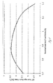
- the flame kernel propagates in the combustion chamber 12 at a rate which may be dependent on the pressure of, and/or the ratio between, the air and fuel mixture in the combustion chamber 12 (among other factors). This propagation rate is known as the burn rate.
- FIG. 4 is a curve that illustrates an example rate at which the flame kernel propagates in the combustion chamber 12 at various ratios between air and fuel in the combustion chamber 12 for a given pressure of gasses in the combustion chamber 12.
- the pressure in the combustion chamber 12 when the flame kernel is initiated may be primarily related to the intake manifold pressure 23 as measured by pressure sensor 21.
- the initial quantity of air and fuel in the combustion chamber 12 may be estimated using a volumetric efficiency table and the pressure of the gas in the intake manifold 23.
- FIG. 5 illustrates an example relationship between various momentary angles A and (i) the pressure of the gas in combustion chamber 12 and (ii) the percentage of the air and fuel mixture in the combustion chamber 12 that has burned.
- the process may further include [604] calculating a speed and angular acceleration of a component of the internal combustion engine 10.
- the speed and angular acceleration of the component may be calculated using the input from the sensing system 50, such as the crankshaft position from a crankshaft position sensor.
- the speed and angular acceleration of the internal combustion engine 10 may be calculated (such as by the controller 40) by determining a time that the internal combustion engine 10 (or a component of the internal combustion engine 10) is at a first position and determining a time that the internal combustion engine 10 (or the component of the internal combustion engine 10) is at a second position to establish the total time difference it takes to move between the first position and the second position.
- the process may further include [614] determining air volume in the combustion chamber 12.
- the air volume in the combustion chamber 12 may be determined from a volumetric efficiency table based on the pressure of the air in the intake manifold 23 as measured by the pressure sensor 21 and the angular speed of the rotating component 20, such as the crankshaft 22.
- the process may further include [622] calculating the heat transfer rate to the piston 15.
- the heat transfer rate to the piston 15 may be determined from a heat transfer table based on the difference between the temperature of the air and fuel in the combustion chamber 12 and the engine oil temperature 26 as measured by a temperature sensor 28.
- engine oil temperature may also be estimated based on internal combustion engine 10 load and operating time of the internal combustion engine 10 (among other methods of determining engine oil temperature).
- the process may further include calculating the released heat remaining in the combustion gas.
- the released heat remaining in the combustion gas may be calculated by multiplying the difference between the temperature of the air and fuel in the combustion chamber 12 and the expected adiabatic temperature of the gas in the combustion chamber by the volume of the gas in the combustion chamber 12.
- the process may further include [650] tracking a slope of a burn rate curve (see, e.g., burn rate curve illustrated in FIG. 4 ).
- the slope of the burn rate curve may be established by comparing the burn rate of consecutive cycles of the internal combustion engine 10 and quantity of fuel injected into the combustion chamber 12 for the corresponding consecutive cycles of the internal combustion engine 10.
- Some burn rates may be equated to more than one air and fuel ratio. Therefore, it may be useful to establish the slope of the burn rate curve in order to determine the appropriate air and fuel ratio at a specific burn rate. As an example, when the slope of the burn rate curve is negative the internal combustion engine 10 is operating with an excess of air (lean).
- the method may further include [715] estimating pressure in the combustion chamber 12 based on momentary volume of the control volume and the momentary expansion acceleration of the control volume.
- the pressure in the control volume may be determined by multiplying the momentary expansion acceleration of the control volume by an inertia of a moving element that forms part of a boundary of the control volume to calculate a force on the moving element.
- the pressure in the control volume may then be determined by dividing the force on the moving element by the surface area of the moving element that forms part of the boundary of the control volume.
- FIGS. 8A and 8B show an example sensing system 50 for measuring momentary angle A of a rotating component 20.
- Sensing system 50 may include a gear 52 that is attached to the rotating component 20 such that the angular position of the gear 52 establishes the angular position of the rotating component 20.
- the gear 52 may include a plurality of teeth 54 (or alternatively a plurality of grooves) around an outer periphery of the gear 52.
- the gear 52 may be missing teeth as indicated by gap 56 to provide a position reference for gear 52.
- some of the plurality of teeth 54 may be elongated or positioned asymmetrically around an outer periphery of the gear 52 to provide a position reference for gear 52.
- the teeth 54 and the gap 56 on the gear 52 may be detected using various sensors, such as a variable reluctance sensor 57 (or a Hall effect sensor).
- the sensing system 50 may detect the position of any component in the internal combustion engine 10 which permits determination of the combustion chamber volume and may not include determining the position of a rotating component in the internal combustion engine 10. As an example, the sensing system 50 may measure a position of one or more piston(s) 15 in the internal combustion engine 10.
- the controller 40 may calculate a speed and an acceleration of the crankshaft 22 based on the detected position of the crankshaft 22. Once the controller 40 calculates a speed and an acceleration of the crankshaft 22, the controller 40 may determine a burn rate of the air and fuel in the combustion chamber 12 based on the speed, acceleration and detected position of the rotating component. As an example, the controller 40 may further calculate the ratio between air and fuel in the combustion chamber 12 based on the determined burn rate.
- the controller 40 may adjust a quantity of fuel provided to the combustion chamber 12 based partially on the calculated ratio between air and fuel in the combustion chamber 12.
- the controller 40 may calculate the ratio between air and fuel in each of the plurality of combustion chambers 12 and individually adjust a quantity of fuel to each combustion chamber 12.
- the controller 40 may detect abnormal combustion of air and fuel within the combustion chamber 12 in some example internal combustion engines 10.
- An example of abnormal combustion of air and fuel may be when the combustion chamber 12 experiences a misfire. Abnormal combustion within the combustion chamber 12 may generate sensed characteristics that would indicate erroneous air and fuel ratio data.
- the controller 40 may discard the sensed data and/or ignore a calculated air and fuel ratio for that cycle.
- the controller 40 may resume recognizing the sensed characteristics and/or calculating the air and fuel ratio when the combustion chamber 12 experiences normal combustion.
- the controller 40 may continue to calculate air and fuel ratios during abnormal combustions, but may not act to control or adjust quantities of air or fuel provided to the combustion chamber based on the calculated air and fuel ratio during (or shortly after) the abnormal combustion. Other variations are possible.
- the methods described herein may allow a ratio between air and fuel in a combustion chamber 12 of an internal combustion engine 10 to be determined.
- the internal combustion engine 10 may or may not additionally include an oxygen sensor 38 that measures oxygen content in the exhaust gasses, which may be used to calculate a ratio between air and fuel in all combustion chambers 12 in the internal combustion engine 10.
- the methods described herein may allow control of additional engine parameters.
- estimating the temperature and pressure of gas in the combustion chamber 12 as described herein may enable fuel that is supplied to a compression ignition engine to be controlled in order to control temperature and/or pressure of gas in the combustion chamber 12.
- the temperature and/or pressure of gas in the combustion chamber 12 may be controlled by adjusting the quantity of fuel provided to the combustion chamber 12 during the combustion process in response to the estimated temperature and pressure of the gas in the combustion chamber 12.
- the timing of the ignition event in the combustion chamber 12 may be controlled based on comparing the estimated burn rate using the example methods described herein to burn rate tables in order to optimize the efficiency of the internal combustion engine 10.
- the burn rate tables may provide optimum burn rates at various positions, such as momentary angle A, of a component (such as crankshaft 22) in the internal combustion engine 10.
- the timing of the ignition event in the combustion chamber 12 may be optimized for both spark ignited and compression ignited internal combustion engines 10.
- controller 40 may include circuitry in a controller, a microprocessor, or an application specific integrated circuit (ASIC), or may be implemented with discrete logic or components, or a combination of other types of analog or digital circuitry, combined on a single integrated circuit or distributed among multiple integrated circuits.
- ASIC application specific integrated circuit
Landscapes
- Engineering & Computer Science (AREA)
- Chemical & Material Sciences (AREA)
- Combustion & Propulsion (AREA)
- Mechanical Engineering (AREA)
- General Engineering & Computer Science (AREA)
- Physics & Mathematics (AREA)
- General Physics & Mathematics (AREA)
- Combined Controls Of Internal Combustion Engines (AREA)
- Electrical Control Of Air Or Fuel Supplied To Internal-Combustion Engine (AREA)
Abstract
Description
- Embodiments pertain to an internal combustion engine, and more particularly to calculating air/fuel ratio used in combustion chambers within an internal combustion engine.
- A typical engine has an exhaust manifold that receives and combines exhaust gasses from each cylinder of the engine and directs the combined exhaust gasses from the engine to an exhaust system and eventually to the atmosphere. An operating variable is typically monitored with a feedback sensor located in the exhaust stream which provides a feedback signal to an electronic controller. As an example, the controller may provide data relative to the air/fuel ratio of the internal combustion engine.
- One common variable that is monitored by the feedback sensor is oxygen concentration in exhaust gases. When the monitored variable is exhaust oxygen concentration in exhaust gases, the feedback sensor may be a narrow-band oxygen sensor.
- The exhaust sensor in some internal combustion engine directly measures oxygen content of the combined exhaust from all cylinders in the engine. This data typically does not directly correlate to the actual ratio between air and fuel in each individual cylinder that is part of the internal combustion engine.
-
-
FIG. 1 illustrates an example combustion chamber of an internal combustion engine. -
FIG. 2 illustrates an example portion of an internal combustion engine that includes a plurality of combustion chambers. -
FIG. 3 illustrates an example portion of an internal combustion engine that includes a plurality of sensors. -
FIG. 4 is an example curve illustrating burn rate at various ratios between air and fuel at a given air pressure in the intake manifold. -
FIG. 5 is an example graph illustrating pressure and burn rate of an air and fuel mixture at various momentary crank angles. -
FIGS. 6A-6B are flowcharts illustrating an example process for calculating a ratio between air and fuel in a combustion chamber. -
FIG. 7 is a flowchart illustrating another example process for calculating a ratio between air and fuel in a control volume. -
FIG. 8 illustrates an example sensing system of measuring momentary angle of a rotating component. -
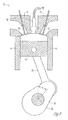
FIG. 9 illustrates an example combustion chamber of a compression ignition engine. - The following description and the drawings sufficiently illustrate specific embodiments to enable those skilled in the art to practice them. Other embodiments may incorporate structural, logical, electrical, process, and other changes. Portions and features of some embodiments may be included in, or substituted for, those of other embodiments. Embodiments set forth in the claims encompass all available equivalents of those claims.
-
FIGS. 1-3 illustrate an exampleinternal combustion engine 10. Theinternal combustion engine 10 may include at least onecombustion chamber 12. The combustion chamber(s) 12 may be bounded by acylinder head 13, acylinder block 14 and apiston 15. - The
internal combustion engine 10 may further include anintake valve 17 for selectively permitting air and fuel to enter thecombustion chamber 12, and anexhaust valve 18 for selectively permitting combustion byproducts to exit thecombustion chamber 12. - The
internal combustion engine 10 may additionally or alternatively include aspark plug 19. Thespark plug 19 may use electrical energy to ignite the air and fuel mixture in thecombustion chamber 12 by initiating a flame kernel. - The flame kernel propagates in the
combustion chamber 12 at a rate which may be dependent on the pressure of, and/or the ratio between, the air and fuel mixture in the combustion chamber 12 (among other factors). This propagation rate is known as the burn rate.FIG. 4 is a curve that illustrates an example rate at which the flame kernel propagates in thecombustion chamber 12 at various ratios between air and fuel in thecombustion chamber 12 for a given pressure of gasses in thecombustion chamber 12. The pressure in thecombustion chamber 12 when the flame kernel is initiated may be primarily related to theintake manifold pressure 23 as measured by pressure sensor 21. - As the flame kernel propagates in the
combustion chamber 12, the flame kernel may generate heat. Some of generated heat is transferred to thecylinder head 13, thecylinder block 14 and thepiston 15. In addition, some of the generated heat may cause the gas in thecombustion chamber 12 to expand. The expanded gas may create an increased pressure which applies a force to thepiston 15. Part or all of the remainder of the generated heat may exit thecombustion chamber 12 when theexhaust valve 18 opens. - The rate that the generated heat is transferred to the
cylinder head 13, thecylinder block 14 and thepiston 15 may be largely dependent on the temperature of thecylinder head 13, thecylinder block 14 and thepiston 15. The temperature of thecylinder head 13 and thecylinder block 14 may be primarily related to the temperature of a coolant flowing through thecylinder head 13 and through thecylinder block 14. The coolant may be a liquid coolant, such asliquid coolant 27 shown inFIG. 3 , or air. - The temperature of the
piston 15 may be primarily related to the temperature of theengine lubricating oil 26. As an example, the temperature of theengine lubricating oil 26 may be measured by atemperature sensor 28, with a different sensor, or in a different manner. - The
piston 15 may be connected to a rotatingcomponent 20 of theinternal combustion engine 10 via some form of a connectinglink 16. As an example, therotating component 20 of theinternal combustion engine 10 may be acrankshaft 22. Thepiston 15 may reciprocate back and forth as thecrankshaft 22 rotates. - The force applied to the reciprocating piston(s) 15 may be applied to
crankshaft 22 at an angle A resulting in torque being applied to thecrankshaft 22. The momentary torque applied to thecrankshaft 22 may be determined based on the angular acceleration of thecrankshaft 22 and a known inertia of thecrankshaft 22. The momentary force applied to the reciprocating piston(s) 15 may be calculated based on the momentary torque applied to thecrankshaft 22 and the momentary angle A. - The reciprocating
piston 15 has a known area. Therefore, the momentary pressure against thepiston 15 may be calculated from the momentary force that is applied to the reciprocating piston(s) 15. The momentary burn rate may be calculated based on the estimated initial quantity of air and fuel in thecombustion chamber 12 and the momentary pressure of the gas against the reciprocatingpiston 15. - The ratio between the air and fuel in the
combustion chamber 12 may be calculated based on the momentary burn rate and the momentary pressure of the gas in thecombustion chamber 12. - The initial quantity of air and fuel in the
combustion chamber 12 may be estimated using a volumetric efficiency table and the pressure of the gas in theintake manifold 23.FIG. 5 illustrates an example relationship between various momentary angles A and (i) the pressure of the gas incombustion chamber 12 and (ii) the percentage of the air and fuel mixture in thecombustion chamber 12 that has burned. - The
internal combustion engine 10 may include additional sensors. As examples, theinternal combustion engine 10 may include a throttle position sensor, an air mass flow rate meter, a volumetric flow meter, a fuel pressure sensor (among other sensors). These sensors may be used to estimate the initial quantity of air and fuel in the combustion chamber 12 (among other functions). - The
internal combustion engine 10 may include or connect with acontroller 40. Thecontroller 40 may calculate a ratio between air and fuel in thecombustion chamber 12 based on the detected position of the rotatingcomponent 20. Thecontroller 40 may receive data from various sensors and perform various calculations necessary to determine the ratio between air and fuel in thecombustion chamber 12. Thecontroller 40 of theinternal combustion engine 10 may also control (such as with control signals) the pulse width offuel injector 34 and/or the ignition timing of theinternal combustion engine 10. - The
controller 40 may additionally or alternatively estimate the initial quantity of air and fuel in thecombustion chamber 12 using the pulse width of thefuel injector 34 and/or the ignition timing of the internal combustion engine 10 (among other functions). The initial quantity of air and fuel in thecombustion chamber 12 determines the charge density of air and fuel in thecombustion chamber 12. The expected burn rate of the air and fuel in thecombustion chamber 12 may be related to the charge density of air and fuel in thecombustion chamber 12. -
FIGS. 6A-6B illustrate an example method or process [600] by which a ratio between air and fuel in aparticular combustion chamber 12 may be calculated. The ratio between air and fuel may be based on the pressure in theintake manifold 23 as measured by an intake manifold pressure sensor 21, engine coolant temperature as measured by acoolant temperature sensor 24 and momentary angle A as measured by sensingsystem 50, or may be based on other variables. - The process [600] may be performed by the
controller 40 or various other components. The process [600] may be implemented as logic, which thecontroller 40 may perform. - The process may include [602] determining a position of the internal combustion engine 10 (or a component of the
internal combustion engine 10, such as thecrankshaft 22 or a piston 15) based on input from asensing system 50. As an example, thesensing system 50 may be a crankshaft position sensor, which may send information about a crankshaft position to thecontroller 40. - The process may further include [604] calculating a speed and angular acceleration of a component of the
internal combustion engine 10. The speed and angular acceleration of the component may be calculated using the input from thesensing system 50, such as the crankshaft position from a crankshaft position sensor. As an example, the speed and angular acceleration of theinternal combustion engine 10 may be calculated (such as by the controller 40) by determining a time that the internal combustion engine 10 (or a component of the internal combustion engine 10) is at a first position and determining a time that the internal combustion engine 10 (or the component of the internal combustion engine 10) is at a second position to establish the total time difference it takes to move between the first position and the second position. - The speed of the internal combustion engine 10 (or a component of the internal combustion engine 10), such as
rotating component 20, may be determined by dividing the distance between the first position and the second position by the total time difference it takes to move between the first position and the second position. The angular acceleration of therotating component 20 may then be determined by the difference between a first speed of therotating component 20 at one point in time and a second speed of therotating component 20 at a second point in time and then dividing the difference in speed by the total time between the first point in time and the second point in time. Other variations are possible. It should be noted that some portions of the specification may interchangeably refer to the position, speed and acceleration of theinternal combustion engine 10 and/or the position, speed and acceleration of the rotating component 20 (or another component of the internal combustion engine 10). - The process may further include [606] calculating
internal combustion engine 10 torque from angular acceleration. As an example, the torque produced by theinternal combustion engine 10 may be directly proportional to the rate at which the rotatingcomponent 20 angularly accelerates and the inertia of therotating component 20. The inertia of theinternal combustion engine 10 may be a fixed quantity and may include contributions fromcrankshaft 22,piston 15, connectingrod 16 and other components driven by theinternal combustion engine 10. Thus, the torque may be estimated by multiplying the inertia of theinternal combustion engine 10 and the calculated angular acceleration. - The process may further include [608] calculating a force on a
particular piston 15. The force may be calculated based on the torque and position of theinternal combustion engine 10. As an example, the moment arm of the crankshaft 22 (which may be or correspond to the position of the internal combustion engine 10) may vary as the momentary angle A changes. Theinternal combustion engine 10 torque produced may be proportional to the product of the moment arm and the force on theparticular piston 15. As such, the force on theparticular piston 15 may be calculated (such as by the controller 40) as the torque divided by the moment arm. - The process may further include [610] calculating pressure of a gas in the
particular combustion chamber 12 based on the force on aparticular piston 15 and the area of thepiston 15. The force on theparticular piston 15 may be proportional to the product of the pressure of the gas in theparticular combustion chamber 12 and the area of thepiston 15, which may be a known or calculable value. As such, the pressure of the gas may be calculated (such as by controller 40) as the calculated force divided by the area of thepiston 15. - The process may further include [612] calculating (or estimating) the temperature of the gas in the
particular combustion chamber 12. The temperature of the gas may be calculated or estimated based on the pressure of the gas in theparticular combustion chamber 12. As an example, the relationship between gas temperature and gas pressure in theparticular combustion chamber 12 may be estimated using the ideal gas law. - The process may further include [614] determining air volume in the
combustion chamber 12. As an example, the air volume in thecombustion chamber 12 may be determined from a volumetric efficiency table based on the pressure of the air in theintake manifold 23 as measured by the pressure sensor 21 and the angular speed of therotating component 20, such as thecrankshaft 22. - In some example methods, the process may further include [615] determining an air mass in the
combustion chamber 12. The air density may be determined from an air density table based on intake air temperature as measured bytemperature sensor 25. The air mass may be calculated by multiplying the air density by the air volume in thecombustion chamber 12. - The temperature of the air in the
intake manifold 23 may also be used to determine an initial temperature in thecombustion chamber 12. - The process may further include [616] calculating an expected adiabatic gas pressure in the combustion chamber, such as by using the ideal gas law and/or Boyles law. The process may further include [618] calculating expected adiabatic gas temperature in the combustion chamber using the expected adiabatic gas pressure in the combustion chamber. As an example, the expected adiabatic pressure and temperature in the combustion chamber may be estimated using the ideal gas law based on the momentary crank angle A and the pressure and temperature of the air and fuel mixture in the
intake manifold 23. - The process may further include [620] calculating the heat transfer rate to the
cylinder head 13 and thecylinder block 14. As an example, the heat transfer rate to thecylinder head 13 and thecylinder block 14 may be determined from a heat transfer table based on the difference between the temperature of the air and fuel in thecombustion chamber 12 and the engine coolant temperature as measured bytemperature sensor 24. - The process may further include [622] calculating the heat transfer rate to the
piston 15. As an example, the heat transfer rate to thepiston 15 may be determined from a heat transfer table based on the difference between the temperature of the air and fuel in thecombustion chamber 12 and theengine oil temperature 26 as measured by atemperature sensor 28. In addition, engine oil temperature may also be estimated based oninternal combustion engine 10 load and operating time of the internal combustion engine 10 (among other methods of determining engine oil temperature). - The process may further include calculating the released heat remaining in the combustion gas. As an example, the released heat remaining in the combustion gas may be calculated by multiplying the difference between the temperature of the air and fuel in the
combustion chamber 12 and the expected adiabatic temperature of the gas in the combustion chamber by the volume of the gas in thecombustion chamber 12. - The process may further include [625] calculating released heat remaining in the gas in the
combustion chamber 12. As an example, the released heat remaining in the gas in thecombustion chamber 12 may be determined by the difference between the temperature of the gas in thecombustion chamber 12 and the expected adiabatic temperature of the gas in thecombustion chamber 12. - The process may further include [630] calculating a total heat released into the gas in the
combustion chamber 12. The total heat released into the gas in thecombustion chamber 12 may be calculated as the sum of the heat transfer rates to thecylinder head 13,cylinder block 14 andpiston 15 and the released heat remaining in the gas in thecombustion chamber 12. - The process may further include [640] calculating a burn rate of the air and fuel in the
combustion chamber 12 based on the total heat released into the gas in thecombustion chamber 12 and the mass of air and fuel in thecombustion chamber 12. - The process may further include [650] tracking a slope of a burn rate curve (see, e.g., burn rate curve illustrated in
FIG. 4 ). The slope of the burn rate curve may be established by comparing the burn rate of consecutive cycles of theinternal combustion engine 10 and quantity of fuel injected into thecombustion chamber 12 for the corresponding consecutive cycles of theinternal combustion engine 10. - The process may further include [660] calculating the air and fuel ratio in the
combustion chamber 12. As an example, the air and fuel ratio in thecombustion chamber 12 may be determined from a table that includes data relating burn rate to a ratio between air and fuel in thecombustion chamber 12 based on the burn rate of the air and fuel in thecombustion chamber 12 and the slope of the burn rate curve. - Some burn rates may be equated to more than one air and fuel ratio. Therefore, it may be useful to establish the slope of the burn rate curve in order to determine the appropriate air and fuel ratio at a specific burn rate. As an example, when the slope of the burn rate curve is negative the
internal combustion engine 10 is operating with an excess of air (lean). - The method of
FIGS. 6A-6B may be utilized to determine or calculate a ratio between air and fuel in aparticular combustion chamber 12. Calculating the ratio between air and fuel in theparticular combustion chamber 12 in such a manner may enable theengine 10 to quickly adjust to changing system dynamics and more accurately maintain an efficient ratio between air and fuel. The method ofFIGS. 6A-6B may be performed continuously, at intervals, when triggered by an event, randomly, or at various other times. One or more blocks of the method may be performed in a different order. For example, thecontroller 40 may calculate the heat transfer rate to the piston [622] after or concurrently with the calculation of the heat transfer rate to the cylinder head and engine block [620]. Additionally or alternatively, one or more blocks of the method ofFIGS. 6A-6B may be omitted, new blocks may be added, and one or more blocks may be modified or altered. Other variations are possible. -
FIG. 7 is a flowchart illustrating an example method or process [700] for calculating a ratio between air and fuel in a control volume. As used herein, a control volume may be defined as a bounded space such that all mass that enters or exits the bounded space is measured. Physical characteristics of the mass contained within the bounded space may be measured or estimated. - The method [700] may be performed by the
controller 40 or various other components. The method [700] may be implemented as logic, which thecontroller 40 may perform. - The method may include [705] calculating expansion speed of an air and fuel mixture in a control volume. As an example, the expansion speed may be calculated by determining a rate of change of the control volume.
- The method may further include [710] calculating momentary expansion acceleration of the air and fuel mixture in the control volume. As an example, the acceleration of the volume of the air and fuel mixture in the control volume may be calculated by the difference between a first expansion speed of the control volume at one point in time and a second expansion speed of the control volume at a second point in time and then dividing the difference between the first and second expansion speeds by the total time between the first point in time and the second point in time.
- The method may further include [715] estimating pressure in the
combustion chamber 12 based on momentary volume of the control volume and the momentary expansion acceleration of the control volume. As an example, the pressure in the control volume may be determined by multiplying the momentary expansion acceleration of the control volume by an inertia of a moving element that forms part of a boundary of the control volume to calculate a force on the moving element. The pressure in the control volume may then be determined by dividing the force on the moving element by the surface area of the moving element that forms part of the boundary of the control volume. - The method may further include [720] estimating a temperature in the
combustion chamber 12 based on the pressure in the control volume. As an example, the temperature may be estimated using the pressure in the control volume and the momentary volume of the control volume using the ideal gas law. - The method may further include [725] estimating an amount of heat that is released from the air and fuel mixture in the control volume during combustion of the air and fuel in the control volume based on the temperature of the air and fuel mixture in the control volume. As an example, the temperature of the air and fuel mixture in the control volume may be compared with a calculated adiabatic temperature of the air and fuel mixture in the control volume to determine the amount of heat released from the air and fuel mixture in the control volume during combustion.
- The method may further include [730] estimating the burn rate based on the amount of heat released from the air and fuel mixture in the control volume during combustion. As an example, the burn rate may be estimated by dividing the amount of heat released from the air and fuel mixture in the control volume during combustion by the total chemical energy contained in the air and fuel mixture.
- The method may further include [735] calculating the ratio between air and fuel based on the burn rate of the air and fuel mixture in the control volume. As an example, the air and fuel ratio in the control volume may be determined from a table that includes data relating burn rate to a ratio between air and fuel in the control volume based on the burn rate of the air and fuel in the control volume.
- As an example, it may be useful to detect the relationship between burn rate and provided fuel to the air and fuel mixture in the control volume in order to establish a slope of a burn rate curve. The slope of the burn rate curve may be used to determine if combustion in the control volume is occurring with excess air (i.e., lean) or excess fuel (i.e., rich).
- The method of
FIG. 7 may be utilized to determine or calculate a ratio between air and fuel in aparticular combustion chamber 12. Calculating the ratio between air and fuel in theparticular combustion chamber 12 in such a manner may be used with various types of internal combustion engines and with or without monitoring a rotating component in an internal combustion engine. The method ofFIG. 7 may be performed continuously, at intervals, when triggered by an event, randomly, or at various other times. One or more blocks of the method may be performed in a different order. Additionally or alternatively, one or more blocks of the method ofFIG. 7 may be omitted, new blocks may be added, and one or more blocks may be modified or altered. Other variations are possible. -
FIGS. 8A and 8B show anexample sensing system 50 for measuring momentary angle A of arotating component 20.Sensing system 50 may include agear 52 that is attached to therotating component 20 such that the angular position of thegear 52 establishes the angular position of therotating component 20. Thegear 52 may include a plurality of teeth 54 (or alternatively a plurality of grooves) around an outer periphery of thegear 52. Thegear 52 may be missing teeth as indicated bygap 56 to provide a position reference forgear 52. Alternatively, some of the plurality ofteeth 54 may be elongated or positioned asymmetrically around an outer periphery of thegear 52 to provide a position reference forgear 52. Theteeth 54 and thegap 56 on thegear 52 may be detected using various sensors, such as a variable reluctance sensor 57 (or a Hall effect sensor). - The
sensing system 50 that detects the speed and position of thecrankshaft 22 may use a single sensor or a combination of sensors. As an example, thesensing system 50 may further include a position sensor on another rotating component of theinternal combustion engine 10 such as a camshaft or dynamic balancing member. - The
sensing system 50 may detect the position of any component in theinternal combustion engine 10 which permits determination of the combustion chamber volume and may not include determining the position of a rotating component in theinternal combustion engine 10. As an example, thesensing system 50 may measure a position of one or more piston(s) 15 in theinternal combustion engine 10. - The
sensing system 50 may use a variety of sensors to establish a position of therotating component 20. Some examples include a resistive position sensor and an optical position sensor such as an optical encoder (among other optical devices). - A
controller 40 may calculate a ratio between air and fuel in the combustion chamber(s) 12 based on the detected angular position of therotating component 20. - As an example, the
controller 40 may calculate a speed and an acceleration of thecrankshaft 22 based on the detected position of thecrankshaft 22. Once thecontroller 40 calculates a speed and an acceleration of thecrankshaft 22, thecontroller 40 may determine a burn rate of the air and fuel in thecombustion chamber 12 based on the speed, acceleration and detected position of the rotating component. As an example, thecontroller 40 may further calculate the ratio between air and fuel in thecombustion chamber 12 based on the determined burn rate. - The
controller 40 may adjust a quantity of fuel provided to thecombustion chamber 12 based partially on the calculated ratio between air and fuel in thecombustion chamber 12. When theinternal combustion engine 10 includes a plurality ofcombustion chambers 12, thecontroller 40 may calculate the ratio between air and fuel in each of the plurality ofcombustion chambers 12 and individually adjust a quantity of fuel to eachcombustion chamber 12. - The
controller 40 may alternatively, or additionally, calculate the ratio between air and fuel within thecombustion chamber 12 based on the angular position of thecrankshaft 22 andadditional controller 40 characteristics of theinternal combustion engine 10. An exampleadditional controller 40 characteristic of theinternal combustion engine 10 may include a time of initiation of combustion of the air and fuel within thecombustion chamber 12. - The
controller 40 may detect abnormal combustion of air and fuel within thecombustion chamber 12 in some exampleinternal combustion engines 10. An example of abnormal combustion of air and fuel may be when thecombustion chamber 12 experiences a misfire. Abnormal combustion within thecombustion chamber 12 may generate sensed characteristics that would indicate erroneous air and fuel ratio data. When thecontroller 40 recognized or identifies an abnormal combustion of air and fuel, thecontroller 40 may discard the sensed data and/or ignore a calculated air and fuel ratio for that cycle. Thecontroller 40 may resume recognizing the sensed characteristics and/or calculating the air and fuel ratio when thecombustion chamber 12 experiences normal combustion. In some instances, thecontroller 40 may continue to calculate air and fuel ratios during abnormal combustions, but may not act to control or adjust quantities of air or fuel provided to the combustion chamber based on the calculated air and fuel ratio during (or shortly after) the abnormal combustion. Other variations are possible. - The example
internal combustion engine 10 described herein may be a spark ignited engine where fuel is injected directly into thecombustion chamber 12. In this type of engine, theinternal combustion engine 10 may be capable of introducing fuel into thecombustion chamber 12 such that the ratio between air and fuel varies inside thecombustion chamber 12. As an example, theinternal combustion engine 10 may be a direct injected gasoline engine. - The example
internal combustion engine 10 described herein may be a spark ignited engine where fuel in a gaseous form is mixed with the intake air before entering thecombustion chamber 12. In this type of engine, the burn rate of the air and fuel in thecombustion chamber 12 may vary significantly based on the specific heat of the fuel. As an example, the gaseous fuel may be natural gas which may vary in chemical composition depending on the geographical location of the source of the natural gas. - The systems and methods described herein may function with other types of engines. For example,
FIG. 9 shows an example compression ignition engine including afuel injector 29 that selectively provides fuel directly to thecombustion chamber 12. As an example, thecompression ignition engine 10 may operate using diesel fuel. In acompression ignition engine 10, the burn rate may be controlled by adjusting the quantity of fuel provided to thecombustion chamber 12 at various momentary crank angles A. - The methods described herein may allow a ratio between air and fuel in a
combustion chamber 12 of aninternal combustion engine 10 to be determined. In some systems, theinternal combustion engine 10 may or may not additionally include anoxygen sensor 38 that measures oxygen content in the exhaust gasses, which may be used to calculate a ratio between air and fuel in allcombustion chambers 12 in theinternal combustion engine 10. - The ratio between air and fuel that is calculated using the methods described herein (see, for example,
FIGS. 6A-6B ,7 ) may, in contrast, be used to establish a ratio between air and fuel in eachindividual combustion chamber 12. Knowing the ratio between air and fuel in eachcombustion chamber 12 ofinternal combustion engine 10 may provide the ability to control a ratio between air and fuel inindividual combustion chambers 12 ofinternal combustion engine 10. Controlling the ratio between air and fuel inindividual combustion chambers 12 ofinternal combustion engine 10 may decrease the harmful emissions that are produced by theinternal combustion engine 10. The harmful emissions that are produced by theinternal combustion engine 10 may be decreased in part because allcombustion chambers 12 may be individually controlled to an optimum ratio between air and fuel. - The systems and methods described herein may provide improved control feedback to the controller relating to the ratio between air and fuel. The systems and methods may establish a ratio between air and fuel of a first cycle of the
internal combustion engine 10 upon completion of the power stroke of the first cycle. Establishing a ratio between air and fuel upon completion of the power stroke of the first cycle may allow adjustment of the fuel quantity prior to initiation of the intake stroke of a second cycle of theinternal combustion engine 10. In contrast, feedback loops that rely on exhaust sensing may take four or more cycles to adjust to variations in the air to fuel ratios inindividual combustion chambers 12. - In addition, the methods described herein may allow control of additional engine parameters. As an example, estimating the temperature and pressure of gas in the
combustion chamber 12 as described herein may enable fuel that is supplied to a compression ignition engine to be controlled in order to control temperature and/or pressure of gas in thecombustion chamber 12. The temperature and/or pressure of gas in thecombustion chamber 12 may be controlled by adjusting the quantity of fuel provided to thecombustion chamber 12 during the combustion process in response to the estimated temperature and pressure of the gas in thecombustion chamber 12. - As another example, the timing of the ignition event in the
combustion chamber 12 may be controlled based on comparing the estimated burn rate using the example methods described herein to burn rate tables in order to optimize the efficiency of theinternal combustion engine 10. The burn rate tables may provide optimum burn rates at various positions, such as momentary angle A, of a component (such as crankshaft 22) in theinternal combustion engine 10. The timing of the ignition event in thecombustion chamber 12 may be optimized for both spark ignited and compression ignitedinternal combustion engines 10. - Other methods are contemplated wherein the inertia of the
internal combustion engine 10 may not be constant. As an example, the rotatingcomponent 20 may be selectively connected to different loads, such as a transmission. The effective inertia of therotating component 20 may be determined by collecting position speed and angular acceleration data during the intake and exhaust stroke of theinternal combustion engine 10. The pressure of the gas in thecombustion chamber 12 may be known during the intake and exhaust stroke of theinternal combustion engine 10. The calculated effective inertia may then be used to calculate the torque of theinternal combustion engine 10 using any of the methods described herein. - In addition, the methods described herein may be used to establish the mechanical condition of the
internal combustion engine 10. As an example, a valve train failure may decrease the volumetric efficiency of thecombustion chamber 12. This decrease in volumetric efficiency may result in a lower than expected pressure within thecombustion chamber 12. - The methods described herein may also be used to validate various sensors on the
internal combustion engine 10 that are measured by thecontroller 40. As an example, the intake manifold pressure sensor 21 may indicate an inaccurately high intake manifold pressure due to a leak in the connection between theintake manifold 23 and the intake manifold pressure sensor 21. This inaccuratelyhigh intake manifold 23 pressure may indicate to thecontroller 40 that the pressure in thecombustion chamber 12 should be higher than is measured by the methods described herein. - The example systems and methods may be utilized to determine a momentary burn rate in the
combustion chamber 12 in order to control the burn rate in thecombustion chamber 12. Controlling the burn rate may permit theinternal combustion engine 10 to produce fewer harmful emissions. - The example systems and methods may also be utilized to determine a temperature and/or a pressure of a gas in the
combustion chamber 12 in order to control the burn rate in thecombustion chamber 12 such that the temperature and/or pressure of the gas remain below a certain level in thecombustion chamber 12. Controlling the temperature and/or pressure of the gas in thecombustion chamber 12 below a certain level may permit theinternal combustion engine 10 to produce fewer harmful emissions. - The methods, devices, and logic described above may be implemented in many different ways in many different combinations of hardware, software or both hardware and software. For example, all or parts of the
controller 40 may include circuitry in a controller, a microprocessor, or an application specific integrated circuit (ASIC), or may be implemented with discrete logic or components, or a combination of other types of analog or digital circuitry, combined on a single integrated circuit or distributed among multiple integrated circuits. All or part of the logic described above may be implemented as instructions for execution by a processor, controller, or other processing device and may be stored in a tangible or non-transitory machine-readable or computer-readable medium such as flash memory, random access memory (RAM) or read only memory (ROM), erasable programmable read only memory (EPROM) or other machine-readable medium such as a compact disc read only memory (CDROM), or magnetic or optical disk. A product, such as a computer program product, may include a storage medium and computer readable instructions stored on the medium, which when executed in an endpoint, computer system, or other device, cause the device to perform operations according to any of the description above. - The processing capability of the system may be distributed among multiple system components, such as among multiple processors and memories, optionally including multiple distributed processing systems. Parameters, databases, and other data structures may be separately stored and managed, may be incorporated into a single memory or database, may be logically and physically organized in many different ways, and may implemented in many ways, including data structures such as linked lists, hash tables, or implicit storage mechanisms. Programs may be parts (e.g., subroutines) of a single program, separate programs, distributed across several memories and processors, or implemented in many different ways, such as in a library, such as a shared library (e.g., a dynamic link library (DLL)). The DLL, for example, may store code that performs any of the system processing described above.
- The methods described may include determinations in relation to one or more thresholds. While these methods may refer to a determination about whether a parameter exceeds a threshold, the determination may in other variations be whether the parameter is greater than or equal to, less than, equal to, or less than or equal to a threshold. Other variations are possible.
- Although the present invention has been described with reference to specific example embodiments, it will be evident that various modifications and changes may be made to these embodiments without departing from the broader spirit and scope of the invention. Accordingly, the specification and drawings are to be regarded in an illustrative rather than a restrictive sense.
- The Abstract is provided to comply with 37 C.F.R. Section 1.72(b) requiring an abstract that will allow the reader to ascertain the nature and gist of the technical disclosure. It is submitted with the understanding that it will not be used to limit or interpret the scope or meaning of the claims. The following claims are hereby incorporated into the detailed description, with each claim standing on its own as a separate embodiment.
- The invention can also be described by the following clauses:
- 1. An internal combustion engine comprising:
- a combustion chamber;
- a rotating component;
- a sensing system that detects an angular position of the rotating component; and
- a controller that calculates a ratio between air and fuel in the combustion chamber based on the detected position of the rotating component.
- 2. The internal combustion engine of
clause 1, wherein the rotating component is a crankshaft. - 3. The internal combustion engine of
clause 1, wherein the controller calculates a speed of the rotating component and an acceleration of the rotating component based on the detected position of the rotating component. - 4. The internal combustion engine of
clause 3, wherein the controller determines a burn rate of the air and the fuel in the combustion chamber based on the speed of the rotating component, the acceleration of the rotating component, and the detected position of the rotating component. - 5. The internal combustion engine of
clause 4, wherein the controller calculates the ratio between the air and the fuel within the combustion chamber based on changes in the burn rate when the controller initiates specific changes in a quantity of the fuel provided to the combustion chamber. - 6. The internal combustion engine of
clause 1, wherein the controller adjusts a quantity of the fuel provided to the combustion chamber based on the ratio between the air and the fuel in the combustion chamber. - 7. The internal combustion engine of
clause 6, further comprising a plurality of combustion chambers, wherein the controller calculates the ratio between the air and the fuel in each of the plurality of combustion chambers and individually adjusts a quantity of the fuel provided to each combustion chamber. - 8. The internal combustion engine of
clause 1, further comprising a gear that includes teeth, the gear attached to the rotating component; and
wherein the gear has teeth omitted to provide a position reference to the controller
wherein the sensing system detects a position of the rotating component by detecting the teeth on the gear. - 9. The internal combustion engine of
clause 1, wherein the controller calculates the ratio between the air and the fuel within the combustion chamber based on the position of the rotating component and a pressure of the air entering the combustion chamber. - 10. The internal combustion engine of
clause 1, wherein the controller calculates the ratio between air and fuel within the combustion chamber based on the position of the rotating component and a time of initiation of combustion of the air and fuel within the combustion chamber. - 11. The internal combustion engine of
clause 1, wherein the controller ignores or does not calculate the ratio between the air and the fuel within the combustion chamber, and does not adjust a quantity of the fuel provided to the combustion chamber, when the controller detects abnormal combustion of the air and the fuel within the combustion chamber. - 12. The internal combustion engine of
clause 1, wherein the fuel comprises diesel fuel. - 13. The internal combustion engine of
clause 1, wherein the fuel comprises gasoline. - 14. A method comprising:
- receiving data indicating a volume of a combustion chamber; and
- calculating, with a processor, a ratio between air and fuel in the combustion chamber based on the volume of the combustion chamber.
- 15. The method of
clause 14, wherein receiving data indicating the volume of the combustion chamber comprises sensing an angular position of a crankshaft that moves a piston, the piston partially defining the volume of the combustion chamber. - 16. The method of
clause 14, wherein calculating a ratio between the air and fuel in the combustion chamber comprises determining a burn rate of the air and fuel in the combustion chamber based on a first rate of change corresponding to a rate of change of the volume and a second rate of change corresponding to a rate of change of the first rate of change. - 17. The method of
clause 14, further comprising calculating a temperature of the air and the fuel in the combustion chamber; and
adjusting the fuel supplied to the combustion chamber to control the temperature of the air and fuel in the combustion chamber. - 18. The method of
clause 14, further comprising adjusting the fuel supplied to the combustion chamber to control the ratio between the air and the fuel in the combustion chamber. - 19. The method of
clause 14, further comprising calculating a pressure of the air and the fuel in the combustion chamber; and
adjusting the fuel supplied to the combustion chamber to control the pressure of the air and the fuel in the combustion chamber. - 20. The method of
clause 14, further comprising not calculating the ratio between air and fuel within the combustion chamber when the controller detects abnormal combustion of air and fuel within the combustion chamber.
Claims (15)
- An internal combustion engine comprising:a combustion chamber;a rotating component;a sensing system that detects an angular position of the rotating component; anda controller that calculates a ratio between air and fuel in the combustion chamber based on the detected position of the rotating component.
- The internal combustion engine of claim 1, wherein the rotating component is a crankshaft.
- The internal combustion engine of claim 1, wherein the controller calculates a speed of the rotating component and an acceleration of the rotating component based on the detected position of the rotating component.
- The internal combustion engine of claim 3, wherein the controller determines a burn rate of the air and the fuel in the combustion chamber based on the speed of the rotating component, the acceleration of the rotating component, and the detected position of the rotating component.
- The internal combustion engine of claim 4, wherein the controller calculates the ratio between the air and the fuel within the combustion chamber based on changes in the burn rate when the controller initiates specific changes in a quantity of the fuel provided to the combustion chamber.
- The internal combustion engine of claim 1, wherein the controller adjusts a quantity of the fuel provided to the combustion chamber based on the ratio between the air and the fuel in the combustion chamber.
- The internal combustion engine of claim 6, further comprising a plurality of combustion chambers, wherein the controller calculates the ratio between the air and the fuel in each of the plurality of combustion chambers and individually adjusts a quantity of the fuel provided to each combustion chamber.
- The internal combustion engine of claim 1, wherein the controller calculates the ratio between the air and the fuel within the combustion chamber based on (1) the position of the rotating component, and (2) either a pressure of the air entering the combustion chamber or a time of initiation of combustion of the air and fuel within the combustion chamber.
- The internal combustion engine of claim 1, wherein the controller ignores or does not calculate the ratio between the air and the fuel within the combustion chamber, and does not adjust a quantity of the fuel provided to the combustion chamber, when the controller detects abnormal combustion of the air and the fuel within the combustion chamber.
- A method comprising:receiving data indicating a volume of a combustion chamber; andcalculating, with a processor, a ratio between air and fuel in the combustion chamber based on the volume of the combustion chamber.
- The method of claim 10, wherein receiving data indicating the volume of the combustion chamber comprises sensing an angular position of a crankshaft that moves a piston, the piston partially defining the volume of the combustion chamber.
- The method of claim 10, wherein calculating a ratio between the air and fuel in the combustion chamber comprises determining a burn rate of the air and fuel in the combustion chamber based on a first rate of change corresponding to a rate of change of the volume and a second rate of change corresponding to a rate of change of the first rate of change.
- The method of claim 10, further comprising calculating a temperature of the air and the fuel in the combustion chamber; and
adjusting the fuel supplied to the combustion chamber to control the temperature of the air and fuel in the combustion chamber. - The method of claim 10, further comprising adjusting the fuel supplied to the combustion chamber to control the ratio between the air and the fuel in the combustion chamber.
- The method of claim 10, further comprising calculating a pressure of the air and the fuel in the combustion chamber; and
adjusting the fuel supplied to the combustion chamber to control the pressure of the air and the fuel in the combustion chamber.
Applications Claiming Priority (1)
| Application Number | Priority Date | Filing Date | Title |
|---|---|---|---|
| US14/013,398 US9279379B2 (en) | 2013-08-29 | 2013-08-29 | Position based air/fuel ratio calculation in an internal combustion engine |
Publications (3)
| Publication Number | Publication Date |
|---|---|
| EP2843218A2 true EP2843218A2 (en) | 2015-03-04 |
| EP2843218A3 EP2843218A3 (en) | 2015-09-30 |
| EP2843218B1 EP2843218B1 (en) | 2019-03-13 |
Family
ID=50896202
Family Applications (1)
| Application Number | Title | Priority Date | Filing Date |
|---|---|---|---|
| EP14171970.8A Active EP2843218B1 (en) | 2013-08-29 | 2014-06-11 | Position based air/fuel ratio calculation in an internal combustion engine |
Country Status (3)
| Country | Link |
|---|---|
| US (2) | US9279379B2 (en) |
| EP (1) | EP2843218B1 (en) |
| CN (1) | CN104420990B (en) |
Cited By (1)
| Publication number | Priority date | Publication date | Assignee | Title |
|---|---|---|---|---|
| WO2017148671A1 (en) * | 2016-03-02 | 2017-09-08 | Continental Automotive Gmbh | Method and apparatus for ascertaining a point in time for injecting fuel |
Families Citing this family (5)
| Publication number | Priority date | Publication date | Assignee | Title |
|---|---|---|---|---|
| EP2801715B1 (en) * | 2012-01-06 | 2018-11-28 | Toyota Jidosha Kabushiki Kaisha | Intake air volume measuring device for internal combustion engine |
| US9279379B2 (en) * | 2013-08-29 | 2016-03-08 | Kohler Co. | Position based air/fuel ratio calculation in an internal combustion engine |
| US9644559B2 (en) * | 2015-07-22 | 2017-05-09 | Ford Global Technologies, Llc | Systems and methods for improving engine emissions during starting |
| US11415041B2 (en) | 2019-09-16 | 2022-08-16 | Woodward, Inc. | Flame triggered and controlled volumetric ignition |
| US11542884B2 (en) * | 2019-12-23 | 2023-01-03 | GM Global Technology Operations LLC | System and method of heat flow calculation in a physics-based piston temperature model |
Family Cites Families (41)
| Publication number | Priority date | Publication date | Assignee | Title |
|---|---|---|---|---|
| US4361196A (en) | 1980-07-11 | 1982-11-30 | Carmet Company | Roof bit coupling |
| US4621603A (en) | 1985-10-29 | 1986-11-11 | General Motors Corporation | Engine combustion control with fuel balancing by pressure ratio management |
| US4788854A (en) | 1987-12-07 | 1988-12-06 | General Motors Corporation | Method of estimating the fuel/air ratio of an internal combustion engine |
| JP3053197B2 (en) | 1990-07-06 | 2000-06-19 | 三菱電機株式会社 | Control device for internal combustion engine |
| JP2546407Y2 (en) | 1991-02-19 | 1997-09-03 | 株式会社ユニシアジェックス | Oil pump |
| US5622158A (en) | 1994-03-10 | 1997-04-22 | Sanshin Kogyo Kabushiki Kaisha | Feedback control system for marine propulsion engine |
| EP0678861B1 (en) | 1994-04-20 | 2001-07-25 | Canon Kabushiki Kaisha | Optical information recording and/or reproducing apparatus and method with vibration wave driving device or vibration driven motor device |
| US5934230A (en) | 1995-03-20 | 1999-08-10 | Tumic Research B.V. | Method for supplying fuel to a combustion engine, and combustion engine |
| JP3754781B2 (en) | 1996-12-20 | 2006-03-15 | 株式会社 神崎高級工機製作所 | Gear fixing structure of gear pump |
| US6189495B1 (en) | 1998-10-23 | 2001-02-20 | Walbro Corporation | Direct cylinder fuel injection |
| SE521737C2 (en) | 1999-03-05 | 2003-12-02 | Volvo Car Corp | Method for reducing substances in the exhaust gas of an internal combustion engine |
| IT1321203B1 (en) * | 2000-02-01 | 2003-12-31 | Magneti Marelli Spa | METHOD FOR CHECKING THE TITLE OF THE AIR - FUEL MIXTURE IN A COMBUSTION ENGINE. |
| US6250292B1 (en) * | 2000-03-06 | 2001-06-26 | Brunswick Corporation | Method of controlling an engine with a pseudo throttle position sensor value |
| JP4382965B2 (en) | 2000-05-19 | 2009-12-16 | 本田技研工業株式会社 | Fire timing control device at the start of ship propulsion equipment |
| JP4134492B2 (en) | 2000-06-08 | 2008-08-20 | 三菱自動車工業株式会社 | In-cylinder internal combustion engine |
| US6866024B2 (en) | 2001-03-05 | 2005-03-15 | The Ohio State University | Engine control using torque estimation |
| US6691664B2 (en) | 2001-04-12 | 2004-02-17 | Joseph Samuel Pisano | Direct port rotary valve mechanism with variable timing for internal combustion engines |
| JP2003003870A (en) | 2001-06-21 | 2003-01-08 | Sanshin Ind Co Ltd | Valve timing controller for four-cycle engine for outboard motor |
| JP2003013759A (en) | 2001-06-29 | 2003-01-15 | Sanshin Ind Co Ltd | Valve timing control device for four cycle engine for outboard motor |
| JP2003035278A (en) | 2001-07-24 | 2003-02-07 | Honda Motor Co Ltd | Rotary oil pump |
| KR100428343B1 (en) * | 2001-12-18 | 2004-04-28 | 현대자동차주식회사 | Method of controlling air flow for gasoline vehicles |
| US6957365B2 (en) | 2002-08-16 | 2005-10-18 | Sun Microsystems, Inc. | Method and apparatus for using acoustic signals to identify disk drives that are likely to fail |
| US6799422B2 (en) | 2002-08-22 | 2004-10-05 | Westerbeke Corporation | Emissions control |
| JP4214762B2 (en) | 2002-11-08 | 2009-01-28 | 株式会社デンソー | Assembling the torque transmitter |
| US6786200B2 (en) | 2002-11-15 | 2004-09-07 | Woodware Governor Company | Method and apparatus for controlling combustion quality in lean burn reciprocating engines |
| EP1477651A1 (en) | 2003-05-12 | 2004-11-17 | STMicroelectronics S.r.l. | Method and device for determining the pressure in the combustion chamber of an internal combustion engine, in particular a spontaneous ignition engine, for controlling fuel injection in the engine |
| ITPZ20030001A1 (en) | 2003-05-29 | 2004-11-30 | Enrico Nino | LAYERED COMBUSTION SYSTEM FOR ALTERNATIVE ENGINES |
| US7021286B2 (en) | 2004-02-20 | 2006-04-04 | Nissan Motor Co., Ltd. | Ignition timing control for internal combustion engine |
| DE602005021837D1 (en) | 2004-02-20 | 2010-07-29 | Nissan Motor | Ignition control system for an internal combustion engine |
| US20080271699A1 (en) | 2005-06-27 | 2008-11-06 | Jens Wellev | Combustion Engine |
| JP4574576B2 (en) | 2006-03-20 | 2010-11-04 | 本田技研工業株式会社 | Fuel control device for internal combustion engine |
| DE102006053255B3 (en) | 2006-11-08 | 2008-01-10 | Iav Gmbh Ingenieurgesellschaft Auto Und Verkehr | Pressure-measurement method for determining cylinder inner pressure in an internal combustion engine uses a cylinder pressure model with input values such as load, revs and crank angle |
| US7440841B2 (en) * | 2007-01-12 | 2008-10-21 | Delphi Technologies, Inc. | Method of efficiently determining pressure-based combustion parameters for an IC engine |
| JP4876107B2 (en) | 2008-07-18 | 2012-02-15 | 日立オートモティブシステムズ株式会社 | Diagnostic control device for internal combustion engine |
| JP4975054B2 (en) | 2009-04-09 | 2012-07-11 | 三菱電機株式会社 | Ignition diagnostic device for internal combustion engine |
| HUE026544T2 (en) | 2009-06-29 | 2016-06-28 | Jenoe Polgar | Internal combustion engine with separate combustion chamber and a method to achieve modified and controlled autoignition in said chamber |
| JP5103459B2 (en) * | 2009-10-30 | 2012-12-19 | 日立オートモティブシステムズ株式会社 | Engine control device |
| US20120125276A1 (en) | 2010-11-22 | 2012-05-24 | Caterpillar Inc. | Four stroke internal combustion engine having variable valve timing and method |
| US9518523B2 (en) * | 2011-05-16 | 2016-12-13 | Toyota Jidosha Kabushiki Kaisha | Air-fuel ratio imbalance detection device for internal combustion engine |
| JP5883740B2 (en) * | 2012-08-01 | 2016-03-15 | 日立オートモティブシステムズ株式会社 | Thermal air flow sensor |
| US9279379B2 (en) * | 2013-08-29 | 2016-03-08 | Kohler Co. | Position based air/fuel ratio calculation in an internal combustion engine |
-
2013
- 2013-08-29 US US14/013,398 patent/US9279379B2/en active Active
-
2014
- 2014-06-11 EP EP14171970.8A patent/EP2843218B1/en active Active
- 2014-07-07 CN CN201410320065.4A patent/CN104420990B/en not_active Expired - Fee Related
-
2016
- 2016-03-07 US US15/063,193 patent/US9869261B2/en active Active
Non-Patent Citations (1)
| Title |
|---|
| None |
Cited By (4)
| Publication number | Priority date | Publication date | Assignee | Title |
|---|---|---|---|---|
| WO2017148671A1 (en) * | 2016-03-02 | 2017-09-08 | Continental Automotive Gmbh | Method and apparatus for ascertaining a point in time for injecting fuel |
| KR20180110149A (en) * | 2016-03-02 | 2018-10-08 | 콘티넨탈 오토모티브 게엠베하 | Method and apparatus for determining when to inject fuel |
| CN108699993A (en) * | 2016-03-02 | 2018-10-23 | 大陆汽车有限公司 | Method and apparatus for the time point for determining injection fuel |
| CN108699993B (en) * | 2016-03-02 | 2022-06-14 | 大陆汽车有限公司 | Method and device for determining a point in time at which fuel is injected |
Also Published As
| Publication number | Publication date |
|---|---|
| EP2843218B1 (en) | 2019-03-13 |
| EP2843218A3 (en) | 2015-09-30 |
| US20150059698A1 (en) | 2015-03-05 |
| CN104420990A (en) | 2015-03-18 |
| US20160258374A1 (en) | 2016-09-08 |
| US9869261B2 (en) | 2018-01-16 |
| US9279379B2 (en) | 2016-03-08 |
| CN104420990B (en) | 2018-07-17 |
Similar Documents
| Publication | Publication Date | Title |
|---|---|---|
| US9869261B2 (en) | Position based air/fuel ratio calculation in an internal combustion engine | |
| CN100588828C (en) | Control apparatus for internal combustion engine | |
| US10288031B2 (en) | Controller for internal combustion engine | |
| EP1538325B1 (en) | Control device of internal combustion engine | |
| US10450970B2 (en) | Detecting and mitigating abnormal combustion characteristics | |
| US7197916B2 (en) | Misfire detector using linear detection of crankshaft angular speed | |
| JP6262957B2 (en) | Operation method of internal combustion engine | |
| US20170037791A1 (en) | Control apparatus for internal combustion engine | |
| JP6213525B2 (en) | Control device for internal combustion engine | |
| RU2653717C1 (en) | Control device and control method for internal combustion engine | |
| US6332352B1 (en) | Engine torque-detecting method and an apparatus therefor | |
| US9903264B1 (en) | Control system for an engine cylinder with fuel control of pre chamber and main chamber | |
| CN104781523A (en) | Method and device for detecting autoignitions on basis of measured and estimated internal cylinder pressure values of internal combustion engine | |
| JP5910651B2 (en) | Air-fuel ratio detection device for internal combustion engine | |
| US9903293B2 (en) | Diagnostic system for internal combustion engine | |
| JP2011157852A (en) | Control device of internal combustion engine | |
| EP3418541B1 (en) | Method for controlling combustion in engines | |
| JP2012180817A (en) | Device for calculating air-fuel ratio of internal combustion engine | |
| US11454184B2 (en) | Control device for an internal combustion engine | |
| JP2018096355A (en) | Control device of internal combustion engine | |
| JP2017141745A (en) | Control device of internal combustion engine | |
| JP2015218704A (en) | Internal combustion engine control unit | |
| JPH03206360A (en) | Misfired cylinder detection device of internal combustion engine |
Legal Events
| Date | Code | Title | Description |
|---|---|---|---|
| 17P | Request for examination filed |
Effective date: 20140611 |
|
| AK | Designated contracting states |
Kind code of ref document: A2 Designated state(s): AL AT BE BG CH CY CZ DE DK EE ES FI FR GB GR HR HU IE IS IT LI LT LU LV MC MK MT NL NO PL PT RO RS SE SI SK SM TR |
|
| AX | Request for extension of the european patent |
Extension state: BA ME |
|
| PUAI | Public reference made under article 153(3) epc to a published international application that has entered the european phase |
Free format text: ORIGINAL CODE: 0009012 |
|
| PUAL | Search report despatched |
Free format text: ORIGINAL CODE: 0009013 |
|
| AK | Designated contracting states |
Kind code of ref document: A3 Designated state(s): AL AT BE BG CH CY CZ DE DK EE ES FI FR GB GR HR HU IE IS IT LI LT LU LV MC MK MT NL NO PL PT RO RS SE SI SK SM TR |
|
| AX | Request for extension of the european patent |
Extension state: BA ME |
|
| RIC1 | Information provided on ipc code assigned before grant |
Ipc: F02D 41/00 20060101ALN20150827BHEP Ipc: F02D 41/14 20060101AFI20150827BHEP Ipc: F02D 35/02 20060101ALN20150827BHEP |
|
| R17P | Request for examination filed (corrected) |
Effective date: 20160316 |
|
| RBV | Designated contracting states (corrected) |
Designated state(s): AL AT BE BG CH CY CZ DE DK EE ES FI FR GB GR HR HU IE IS IT LI LT LU LV MC MK MT NL NO PL PT RO RS SE SI SK SM TR |
|
| STAA | Information on the status of an ep patent application or granted ep patent |
Free format text: STATUS: EXAMINATION IS IN PROGRESS |
|
| 17Q | First examination report despatched |
Effective date: 20180613 |
|
| GRAP | Despatch of communication of intention to grant a patent |
Free format text: ORIGINAL CODE: EPIDOSNIGR1 |
|
| STAA | Information on the status of an ep patent application or granted ep patent |
Free format text: STATUS: GRANT OF PATENT IS INTENDED |
|
| RIC1 | Information provided on ipc code assigned before grant |
Ipc: F02D 41/14 20060101AFI20180829BHEP Ipc: F02D 35/02 20060101ALN20180829BHEP Ipc: F02D 41/00 20060101ALN20180829BHEP |
|
| INTG | Intention to grant announced |
Effective date: 20180928 |
|
| RIC1 | Information provided on ipc code assigned before grant |
Ipc: F02D 41/14 20060101AFI20180919BHEP Ipc: F02D 35/02 20060101ALN20180919BHEP Ipc: F02D 41/00 20060101ALN20180919BHEP |
|
| RIN1 | Information on inventor provided before grant (corrected) |
Inventor name: DANFORTH III, ROBERT J. Inventor name: FRAMPTON, ISAAC S. |
|
| GRAS | Grant fee paid |
Free format text: ORIGINAL CODE: EPIDOSNIGR3 |
|
| GRAA | (expected) grant |
Free format text: ORIGINAL CODE: 0009210 |
|
| STAA | Information on the status of an ep patent application or granted ep patent |
Free format text: STATUS: THE PATENT HAS BEEN GRANTED |
|
| AK | Designated contracting states |
Kind code of ref document: B1 Designated state(s): AL AT BE BG CH CY CZ DE DK EE ES FI FR GB GR HR HU IE IS IT LI LT LU LV MC MK MT NL NO PL PT RO RS SE SI SK SM TR |
|
| REG | Reference to a national code |
Ref country code: GB Ref legal event code: FG4D |
|
| REG | Reference to a national code |
Ref country code: CH Ref legal event code: EP Ref country code: AT Ref legal event code: REF Ref document number: 1108014 Country of ref document: AT Kind code of ref document: T Effective date: 20190315 |
|
| REG | Reference to a national code |
Ref country code: IE Ref legal event code: FG4D |
|
| REG | Reference to a national code |
Ref country code: DE Ref legal event code: R096 Ref document number: 602014042684 Country of ref document: DE |
|
| REG | Reference to a national code |
Ref country code: NL Ref legal event code: MP Effective date: 20190313 |
|
| REG | Reference to a national code |
Ref country code: LT Ref legal event code: MG4D |
|
| PG25 | Lapsed in a contracting state [announced via postgrant information from national office to epo] |
Ref country code: SE Free format text: LAPSE BECAUSE OF FAILURE TO SUBMIT A TRANSLATION OF THE DESCRIPTION OR TO PAY THE FEE WITHIN THE PRESCRIBED TIME-LIMIT Effective date: 20190313 Ref country code: LT Free format text: LAPSE BECAUSE OF FAILURE TO SUBMIT A TRANSLATION OF THE DESCRIPTION OR TO PAY THE FEE WITHIN THE PRESCRIBED TIME-LIMIT Effective date: 20190313 Ref country code: FI Free format text: LAPSE BECAUSE OF FAILURE TO SUBMIT A TRANSLATION OF THE DESCRIPTION OR TO PAY THE FEE WITHIN THE PRESCRIBED TIME-LIMIT Effective date: 20190313 Ref country code: NO Free format text: LAPSE BECAUSE OF FAILURE TO SUBMIT A TRANSLATION OF THE DESCRIPTION OR TO PAY THE FEE WITHIN THE PRESCRIBED TIME-LIMIT Effective date: 20190613 |
|
| PG25 | Lapsed in a contracting state [announced via postgrant information from national office to epo] |
Ref country code: BG Free format text: LAPSE BECAUSE OF FAILURE TO SUBMIT A TRANSLATION OF THE DESCRIPTION OR TO PAY THE FEE WITHIN THE PRESCRIBED TIME-LIMIT Effective date: 20190613 Ref country code: RS Free format text: LAPSE BECAUSE OF FAILURE TO SUBMIT A TRANSLATION OF THE DESCRIPTION OR TO PAY THE FEE WITHIN THE PRESCRIBED TIME-LIMIT Effective date: 20190313 Ref country code: LV Free format text: LAPSE BECAUSE OF FAILURE TO SUBMIT A TRANSLATION OF THE DESCRIPTION OR TO PAY THE FEE WITHIN THE PRESCRIBED TIME-LIMIT Effective date: 20190313 Ref country code: NL Free format text: LAPSE BECAUSE OF FAILURE TO SUBMIT A TRANSLATION OF THE DESCRIPTION OR TO PAY THE FEE WITHIN THE PRESCRIBED TIME-LIMIT Effective date: 20190313 Ref country code: HR Free format text: LAPSE BECAUSE OF FAILURE TO SUBMIT A TRANSLATION OF THE DESCRIPTION OR TO PAY THE FEE WITHIN THE PRESCRIBED TIME-LIMIT Effective date: 20190313 Ref country code: GR Free format text: LAPSE BECAUSE OF FAILURE TO SUBMIT A TRANSLATION OF THE DESCRIPTION OR TO PAY THE FEE WITHIN THE PRESCRIBED TIME-LIMIT Effective date: 20190614 |
|
| REG | Reference to a national code |
Ref country code: AT Ref legal event code: MK05 Ref document number: 1108014 Country of ref document: AT Kind code of ref document: T Effective date: 20190313 |
|
| PG25 | Lapsed in a contracting state [announced via postgrant information from national office to epo] |
Ref country code: RO Free format text: LAPSE BECAUSE OF FAILURE TO SUBMIT A TRANSLATION OF THE DESCRIPTION OR TO PAY THE FEE WITHIN THE PRESCRIBED TIME-LIMIT Effective date: 20190313 Ref country code: IT Free format text: LAPSE BECAUSE OF FAILURE TO SUBMIT A TRANSLATION OF THE DESCRIPTION OR TO PAY THE FEE WITHIN THE PRESCRIBED TIME-LIMIT Effective date: 20190313 Ref country code: AL Free format text: LAPSE BECAUSE OF FAILURE TO SUBMIT A TRANSLATION OF THE DESCRIPTION OR TO PAY THE FEE WITHIN THE PRESCRIBED TIME-LIMIT Effective date: 20190313 Ref country code: PT Free format text: LAPSE BECAUSE OF FAILURE TO SUBMIT A TRANSLATION OF THE DESCRIPTION OR TO PAY THE FEE WITHIN THE PRESCRIBED TIME-LIMIT Effective date: 20190713 Ref country code: SK Free format text: LAPSE BECAUSE OF FAILURE TO SUBMIT A TRANSLATION OF THE DESCRIPTION OR TO PAY THE FEE WITHIN THE PRESCRIBED TIME-LIMIT Effective date: 20190313 Ref country code: EE Free format text: LAPSE BECAUSE OF FAILURE TO SUBMIT A TRANSLATION OF THE DESCRIPTION OR TO PAY THE FEE WITHIN THE PRESCRIBED TIME-LIMIT Effective date: 20190313 Ref country code: ES Free format text: LAPSE BECAUSE OF FAILURE TO SUBMIT A TRANSLATION OF THE DESCRIPTION OR TO PAY THE FEE WITHIN THE PRESCRIBED TIME-LIMIT Effective date: 20190313 Ref country code: CZ Free format text: LAPSE BECAUSE OF FAILURE TO SUBMIT A TRANSLATION OF THE DESCRIPTION OR TO PAY THE FEE WITHIN THE PRESCRIBED TIME-LIMIT Effective date: 20190313 |
|
| PG25 | Lapsed in a contracting state [announced via postgrant information from national office to epo] |
Ref country code: SM Free format text: LAPSE BECAUSE OF FAILURE TO SUBMIT A TRANSLATION OF THE DESCRIPTION OR TO PAY THE FEE WITHIN THE PRESCRIBED TIME-LIMIT Effective date: 20190313 Ref country code: PL Free format text: LAPSE BECAUSE OF FAILURE TO SUBMIT A TRANSLATION OF THE DESCRIPTION OR TO PAY THE FEE WITHIN THE PRESCRIBED TIME-LIMIT Effective date: 20190313 |
|
| REG | Reference to a national code |
Ref country code: DE Ref legal event code: R097 Ref document number: 602014042684 Country of ref document: DE |
|
| PG25 | Lapsed in a contracting state [announced via postgrant information from national office to epo] |
Ref country code: IS Free format text: LAPSE BECAUSE OF FAILURE TO SUBMIT A TRANSLATION OF THE DESCRIPTION OR TO PAY THE FEE WITHIN THE PRESCRIBED TIME-LIMIT Effective date: 20190713 Ref country code: AT Free format text: LAPSE BECAUSE OF FAILURE TO SUBMIT A TRANSLATION OF THE DESCRIPTION OR TO PAY THE FEE WITHIN THE PRESCRIBED TIME-LIMIT Effective date: 20190313 |
|
| PLBE | No opposition filed within time limit |
Free format text: ORIGINAL CODE: 0009261 |
|
| STAA | Information on the status of an ep patent application or granted ep patent |
Free format text: STATUS: NO OPPOSITION FILED WITHIN TIME LIMIT |
|
| PG25 | Lapsed in a contracting state [announced via postgrant information from national office to epo] |
Ref country code: DK Free format text: LAPSE BECAUSE OF FAILURE TO SUBMIT A TRANSLATION OF THE DESCRIPTION OR TO PAY THE FEE WITHIN THE PRESCRIBED TIME-LIMIT Effective date: 20190313 Ref country code: MC Free format text: LAPSE BECAUSE OF FAILURE TO SUBMIT A TRANSLATION OF THE DESCRIPTION OR TO PAY THE FEE WITHIN THE PRESCRIBED TIME-LIMIT Effective date: 20190313 |
|
| REG | Reference to a national code |
Ref country code: CH Ref legal event code: PL |
|
| 26N | No opposition filed |
Effective date: 20191216 |
|
| PG25 | Lapsed in a contracting state [announced via postgrant information from national office to epo] |
Ref country code: SI Free format text: LAPSE BECAUSE OF FAILURE TO SUBMIT A TRANSLATION OF THE DESCRIPTION OR TO PAY THE FEE WITHIN THE PRESCRIBED TIME-LIMIT Effective date: 20190313 |
|
| REG | Reference to a national code |
Ref country code: BE Ref legal event code: MM Effective date: 20190630 |
|
| PG25 | Lapsed in a contracting state [announced via postgrant information from national office to epo] |
Ref country code: TR Free format text: LAPSE BECAUSE OF FAILURE TO SUBMIT A TRANSLATION OF THE DESCRIPTION OR TO PAY THE FEE WITHIN THE PRESCRIBED TIME-LIMIT Effective date: 20190313 |
|
| PG25 | Lapsed in a contracting state [announced via postgrant information from national office to epo] |
Ref country code: IE Free format text: LAPSE BECAUSE OF NON-PAYMENT OF DUE FEES Effective date: 20190611 |
|
| PG25 | Lapsed in a contracting state [announced via postgrant information from national office to epo] |
Ref country code: LU Free format text: LAPSE BECAUSE OF NON-PAYMENT OF DUE FEES Effective date: 20190611 Ref country code: CH Free format text: LAPSE BECAUSE OF NON-PAYMENT OF DUE FEES Effective date: 20190630 Ref country code: BE Free format text: LAPSE BECAUSE OF NON-PAYMENT OF DUE FEES Effective date: 20190630 Ref country code: LI Free format text: LAPSE BECAUSE OF NON-PAYMENT OF DUE FEES Effective date: 20190630 |
|
| PG25 | Lapsed in a contracting state [announced via postgrant information from national office to epo] |
Ref country code: CY Free format text: LAPSE BECAUSE OF FAILURE TO SUBMIT A TRANSLATION OF THE DESCRIPTION OR TO PAY THE FEE WITHIN THE PRESCRIBED TIME-LIMIT Effective date: 20190313 |
|
| PG25 | Lapsed in a contracting state [announced via postgrant information from national office to epo] |
Ref country code: MT Free format text: LAPSE BECAUSE OF FAILURE TO SUBMIT A TRANSLATION OF THE DESCRIPTION OR TO PAY THE FEE WITHIN THE PRESCRIBED TIME-LIMIT Effective date: 20190313 Ref country code: HU Free format text: LAPSE BECAUSE OF FAILURE TO SUBMIT A TRANSLATION OF THE DESCRIPTION OR TO PAY THE FEE WITHIN THE PRESCRIBED TIME-LIMIT; INVALID AB INITIO Effective date: 20140611 |
|
| PG25 | Lapsed in a contracting state [announced via postgrant information from national office to epo] |
Ref country code: MK Free format text: LAPSE BECAUSE OF FAILURE TO SUBMIT A TRANSLATION OF THE DESCRIPTION OR TO PAY THE FEE WITHIN THE PRESCRIBED TIME-LIMIT Effective date: 20190313 |
|
| P01 | Opt-out of the competence of the unified patent court (upc) registered |
Effective date: 20230707 |
|
| PGFP | Annual fee paid to national office [announced via postgrant information from national office to epo] |
Ref country code: GB Payment date: 20240403 Year of fee payment: 11 |
|
| PGFP | Annual fee paid to national office [announced via postgrant information from national office to epo] |
Ref country code: DE Payment date: 20240607 Year of fee payment: 11 |
|
| PGFP | Annual fee paid to national office [announced via postgrant information from national office to epo] |
Ref country code: FR Payment date: 20240608 Year of fee payment: 11 |
|
| REG | Reference to a national code |
Ref country code: GB Ref legal event code: 732E Free format text: REGISTERED BETWEEN 20240725 AND 20240731 |
|
| REG | Reference to a national code |
Ref country code: DE Ref legal event code: R081 Ref document number: 602014042684 Country of ref document: DE Owner name: DISCOVERY ENERGY, LLC, KOHLER, US Free format text: FORMER OWNER: KOHLER CO., KOHLER, WIS., US |