WO2015104817A1 - Dispositif de commande de véhicule - Google Patents
Dispositif de commande de véhicule Download PDFInfo
- Publication number
- WO2015104817A1 WO2015104817A1 PCT/JP2014/050221 JP2014050221W WO2015104817A1 WO 2015104817 A1 WO2015104817 A1 WO 2015104817A1 JP 2014050221 W JP2014050221 W JP 2014050221W WO 2015104817 A1 WO2015104817 A1 WO 2015104817A1
- Authority
- WO
- WIPO (PCT)
- Prior art keywords
- public road
- vehicle
- mode
- equipment
- vehicle control
- Prior art date
Links
Images
Classifications
-
- B—PERFORMING OPERATIONS; TRANSPORTING
- B60—VEHICLES IN GENERAL
- B60T—VEHICLE BRAKE CONTROL SYSTEMS OR PARTS THEREOF; BRAKE CONTROL SYSTEMS OR PARTS THEREOF, IN GENERAL; ARRANGEMENT OF BRAKING ELEMENTS ON VEHICLES IN GENERAL; PORTABLE DEVICES FOR PREVENTING UNWANTED MOVEMENT OF VEHICLES; VEHICLE MODIFICATIONS TO FACILITATE COOLING OF BRAKES
- B60T8/00—Arrangements for adjusting wheel-braking force to meet varying vehicular or ground-surface conditions, e.g. limiting or varying distribution of braking force
- B60T8/17—Using electrical or electronic regulation means to control braking
- B60T8/1701—Braking or traction control means specially adapted for particular types of vehicles
- B60T8/1706—Braking or traction control means specially adapted for particular types of vehicles for single-track vehicles, e.g. motorcycles
-
- B—PERFORMING OPERATIONS; TRANSPORTING
- B62—LAND VEHICLES FOR TRAVELLING OTHERWISE THAN ON RAILS
- B62J—CYCLE SADDLES OR SEATS; AUXILIARY DEVICES OR ACCESSORIES SPECIALLY ADAPTED TO CYCLES AND NOT OTHERWISE PROVIDED FOR, e.g. ARTICLE CARRIERS OR CYCLE PROTECTORS
- B62J50/00—Arrangements specially adapted for use on cycles not provided for in main groups B62J1/00 - B62J45/00
- B62J50/20—Information-providing devices
- B62J50/25—Information-providing devices intended to provide information to other road users, e.g. signs or flags
- B62J50/26—Number plates
-
- B—PERFORMING OPERATIONS; TRANSPORTING
- B60—VEHICLES IN GENERAL
- B60T—VEHICLE BRAKE CONTROL SYSTEMS OR PARTS THEREOF; BRAKE CONTROL SYSTEMS OR PARTS THEREOF, IN GENERAL; ARRANGEMENT OF BRAKING ELEMENTS ON VEHICLES IN GENERAL; PORTABLE DEVICES FOR PREVENTING UNWANTED MOVEMENT OF VEHICLES; VEHICLE MODIFICATIONS TO FACILITATE COOLING OF BRAKES
- B60T2270/00—Further aspects of brake control systems not otherwise provided for
- B60T2270/10—ABS control systems
Definitions
- the present invention relates to a control device for a vehicle that travels on both a public road and a non-public road area such as a circuit.
- the anti-lock brake system is a device that prevents a wheel from locking and slipping on a road surface during a braking operation on a sudden brake or a low friction road.
- An object of the present invention is to provide a vehicle control device that can change a vehicle to non-public road driving with a simple operation.
- a vehicle control apparatus includes a removal detection means for detecting that an equipment required for traveling on a public road of a vehicle has been removed from a vehicle body, and a detection signal from the removal detection means. Determining means for determining that the vehicle is present in the non-public road region when the determination condition including is included, and a travel control means for receiving the determination signal from the determining means and setting the non-public road mode suitable for non-public road driving And.
- the non-public road mode is, for example, a selectable mode in which the anti-lock brake system can be selected to be inoperative or suppressed.
- the non-public road mode includes changing the display of the meter unit or displaying a dedicated switch for driving on the non-public road.
- the equipment may be at least one of a rearview mirror, a headlight, a brake lamp, a tail lamp, a license plate, a license lamp, a warning whistle, a side stand, and a direction indicator.
- the determination condition may include that two or more pieces of the equipment are removed. Thereby, it can prevent that a vehicle is changed into non-public road driving
- the vehicle further includes a non-public road area detecting means for detecting that the vehicle is present in the non-public road area, and the determination condition includes a detection signal from the non-public road area detecting means.
- a non-public road area detecting means for detecting that the vehicle is present in the non-public road area
- the determination condition includes a detection signal from the non-public road area detecting means.
- the vehicle further includes attachment detection means for detecting that a part used in a non-public road area is attached to the vehicle, and the determination condition includes a detection signal from the attachment detection means.
- Parts used in the non-public road area are, for example, a circuit ECU and an authentication key. According to this configuration, by adding that the parts used in the non-public road region are attached to the determination condition, it is possible to prevent the vehicle from being changed to non-public road travel due to erroneous detection.
- the equipment is an electrical equipment
- the removal detection means detects the removal of the equipment by a detection signal from an operation detection means mounted on a vehicle body in order to detect the operation of the electrical equipment. It is preferable. According to this configuration, it is not necessary to provide a separate sensor as the removal detection means, and an increase in the number of parts can be suppressed.
- the operation detection means detects, for example, a change in power consumption / voltage change of a light bulb, separation of a power supply line, presence or absence of a side stand, and the like.
- the removal of the equipment may be detected by a signal from a sensor that detects the removal of the equipment.
- the vehicle control method of the present invention is a vehicle control method provided with a driving support device, and includes a removal detection step for detecting that predetermined equipment has been removed from the vehicle body, and a detection signal in the removal detection step.
- a selection step that enables selection or selection.
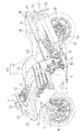
- FIG. 1 is a side view showing a motorcycle that is a type of vehicle equipped with a control device according to a first embodiment of the present invention.
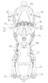
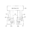
- FIG. 2 is a plan view showing the motorcycle. It is a block diagram of the control apparatus of the same motorcycle. It is a circuit diagram which shows the operation
- left side and right side refer to the left and right sides as viewed from the driver who gets on the vehicle.
- FIG. 1 is a side view of a motorcycle that is a type of vehicle according to a first embodiment of the present invention.
- the body frame FR of the motorcycle shown in FIG. 1 has a main frame 1 constituting the front half and a rear frame 2 connected to the rear part of the main frame 1 and constituting the rear half.
- a front fork 4 is supported at the front end of the main frame 1, a front wheel 6 is attached to the lower end of the front fork 4, and a handle 8 and a meter unit 9 are attached to the upper end of the front fork 4.
- a swing arm bracket 10 is provided at the lower rear end of the main frame 1.
- a swing arm 12 is pivotally supported on the swing arm bracket 10 via a pivot shaft 14 at the front end so as to be swingable up and down.
- a rear wheel 16 is attached to the rear end of the swing arm 12.
- An engine E is attached to the lower part of the main frame 1. The rear wheel 16 is driven by the engine E via the chain 18.
- a side stand 19 is supported on the lower end of the main frame 1 on the left side of the vehicle body.
- the rear frame 2 supports a rider's seat 20 and a passenger's seat 22.
- a fuel tank 24 is attached to the upper part of the main frame 1, that is, between the handle 8 and the rider's seat 20.
- the cowling 26 is supported on the main frame 1 and covers the part from the front of the handle 8 to the side of the engine E.
- a headlight 28 is attached to the front end portion of the cowling 26, and a pair of left and right rearview mirrors 30 are attached to the upper portion of the cowling 26.
- a pair of left and right front direction indicators 32 are attached to the cowling 26 below the headlight 28.
- a tail lamp 34 is attached to the rear end of the rear frame 2.
- the lower portion of the passenger seat 22 in the rear frame 2 is covered from the outside by a pair of left and right rear cowls 36.
- a pair of left and right rear direction indicators 38 are attached to the rear portion of the rear cowl 36 and supported by the rear frame 2.
- a rear flap 40 is supported at the lower rear portion of the rear frame 2.
- a number plate 42 is attached to the rear flap 40, and a license lamp 44 for irradiating the number plate 42 is attached to the upper portion of the rear flap 40.
- a mode changeover switch 46 for switching the traveling mode (traveling mode) of the motorcycle is attached to the left handlebar 8a of the handle 8.
- the mode changeover switch 46 selects a driving mode that affects the driving feeling, such as a mode related to output and a mode related to traction control performance for preventing tire slipping during start / acceleration. Examples of the output mode include a full power mode and a low power mode.
- a brake lever 48 is attached to the right handlebar 8b, and a brake pedal 50 is disposed on the right side of the vehicle body below the rider's seat 20.
- a main switch 52 for starting the operation of the motorcycle is disposed in front of the handle 8.
- the motorcycle according to the present embodiment is a so-called full cowl type in which the entire front portion of the vehicle body is covered with a cowling 26, and is suitable for running on a non-public road area such as a circuit in addition to running on a public road. ing.
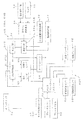
- the motorcycle according to the present embodiment is equipped with an anti-lock brake system ABS, which is a kind of driving support device that supports the driving operation of the driver.
- the anti-lock brake system ABS has an ABS control unit 54, and signals from the front wheel speed sensor 56 and the rear wheel speed sensor 58 are input to the ABS control unit 54. Brake operations from the brake lever 48 and the brake pedal 50 are transmitted to the front wheel brake 60 and the rear wheel brake 62 via the ABS control unit 54. Based on signals from the vehicle speed sensors 58 and 60, the ABS control unit 54 operates the brakes 60 and 62 so as to prevent the wheels from locking and slipping on the road surface when the brake is operated.
- the driving support device detects a vehicle state or a driver's operation and, based on the detection result, determines that the driving support control is necessary, issues a driving support command to the control target.
- the control target includes an electronically controllable device that affects the running feeling. Examples of the control target include a drive device such as an engine or an electric motor, a braking device such as a brake, a shock absorber such as a suspension, a steering device, a power transmission device, and the like.
- the driving assistance device includes traction control (starting assistance device, low ⁇ road running assistance device), electronically controlled suspension, CBS (front and rear wheel brake coordination device), automatic transmission Equipment, electronically controlled steering damper, idling stop, output regulation, vehicle speed regulation, collision damage reduction brake or automatic driving.
- traction control starting assistance device, low ⁇ road running assistance device
- CBS front and rear wheel brake coordination device
- automatic transmission Equipment electronically controlled steering damper
- idling stop output regulation
- vehicle speed regulation collision damage reduction brake or automatic driving.
- the driving support device is equipped with an actuator or sensor that is newly electronically controlled to perform driving support.
- an actuator include an electronically controlled hydraulic unit, an electronically controlled suspension, and an electronically controlled steering damper that are used in an antilock brake system, a front and rear wheel brake coordination device, and the like.
- the motorcycle according to the present embodiment includes a determination unit 64 that determines that the vehicle exists in a non-public road area.
- the determination unit 64 is a program included in the engine control unit ECU.
- the judging means 64 judges the non-public road area by removing the safety parts of the motorcycle.
- a safety part is an equipment that is required by law to ensure safety among the equipment required when traveling on public roads. For example, a sounding device (not shown) ), Rearview mirror 30, headlamp 28, direction indicators 32 and 38, tail lamp 34, and the like.
- the equipment required for traveling on public roads includes the safety plate, the license plate 42, the license lamp 44, the side stand 19, and the like.
- the determination condition 65 for determining that the vehicle exists in the non-public road area by the determination means 64 includes that at least one of the safety parts has been removed. Instead of the safety part, it may be determined that the equipment including the safety part has been removed. In that case, you may make it include that two or more said equipment was removed. Thereby, it can prevent that it determines with a vehicle existing in a non-public road area
- the removal of the equipment including the safety parts is detected by the removal detection means 66.
- the removal detection means 66 detects the removal of the equipment by a detection signal from the motion detection means 68 mounted on the vehicle body in order to detect the operation of the electrical equipment.
- the operation detection unit 68 detects, for example, a change in power consumption / voltage change of a light bulb, disconnection of a power supply line, a side stand sensor, and the like.
- FIG. 4 shows an example of the motion detection means 68.
- the pair of left and right front direction indicators 32 are provided with a detection line L2 for detecting removal separately from the power supply line L1 of the light emitter 32a, and the operation detecting means 68 is connected to the detection line L2.
- a connector 67 is inserted in the power supply line L1 and the detection line L2.
- the motion detection means 68 detects the disconnection of the power supply line L1 and the detection line L2 and outputs a detection signal.
- the detection line L2 separately from the power supply line L1
- a sensor 70 for detecting the removal of the equipment is provided, and the removal of the equipment is detected by a signal from the sensor 70.
- the sensor 70 for example, a mechanical contact switch, a reflective optical sensor, or the like can be used.
- the determination unit 64 determines that the motorcycle exists in the non-public road area by satisfying a determination condition 65 including a detection signal from the removal detection unit 66.
- the determination condition 65 may include, in addition to the detection signal from the removal detection means 66, being less than a predetermined speed or being in a travel stop state. Further, the determination condition 65 may include a slip ratio, a vehicle speed, an acceleration, a deceleration, and the like, which mean the idle speed of either the front or rear wheels. That is, based on these vehicle running states, the vehicle may be regarded as traveling in a non-public road area, and set as one of the conditions existing in the non-public road area. Further, the determination condition 65 may be set so as to invalidate the mode switching during the execution of the assist control. By setting the determination condition 65 in this way, it is possible to prevent the running feeling from being lowered.
- the motorcycle according to the present embodiment includes selection means 55 that enables the antilock brake system ABS to be selected between the public road mode M1 and the non-public road mode M2 when the determination means 64 determines that the motorcycle is in the non-public road area. ing.
- the anti-lock brake system ABS cannot be selected in the non-public road mode M2 unless it is determined that the vehicle is in the non-public road area. In other words, the anti-lock brake system ABS can be selected to the non-public road mode M2 only when it is determined that the motorcycle exists in the non-public road area.
- the selection means 55 is configured to be selectable by the driver in a vehicle travelable state.
- the selection means 55 includes a mode changeover switch 46 and a travel control means 57 that is a program included in the engine control unit ECU.
- the vehicle travelable state includes a stopped state.
- the vehicle travelable state is formed so that it is not necessary to go through a state in which the vehicle cannot travel such as removal of on-vehicle parts before and after the operation.
- the main switch 52 ignition switch
- the selection means 55 is comprised so that selection is possible by the driver of the boarding state.
- a switch used for purposes other than mode selection may also serve as the selection means 55.
- the mode changeover switch 46 has a plurality of selection switches, and the traveling control means 57 determines the selection of the non-public road mode M2 by performing a plurality of switch operations of the mode changeover switch 46.
- the mode changeover switch 46 is one selection switch, the selection of the non-public road mode M2 may be determined by performing an operation for a predetermined time or more of the switch.
- the mode switching operation is performed by simultaneously operating two switches provided on the left and right for a predetermined time or more.
- the mode switch button provided on the meter unit 9 or the handle switch may be operated to make the mode switchable, and the mode switch may be performed using the selection button. In this way, erroneous operation can be prevented by setting the mode switching operation so that a plurality of steps or a standby time is provided instead of one operation.
- the mode change switch 46 may be any switch that is disposed at a position where the driver can operate the vehicle while riding on the vehicle body.
- the meter display mode mode switch for example, in addition to the travel mode change switch, the meter display mode mode switch, Switch (blinker, horn, lamp high / low switch, etc.).
- Switch blink, horn, lamp high / low switch, etc.
- the anti-lock brake system ABS is deactivated.
- the non-public road mode M2 may be changed, for example, so as to weaken the dominant of the antilock brake system ABS or delay the antilock determination.
- the brake operation support by any one of the front and rear hydraulic units may be disabled.
- the driving support amount by the control device is suppressed or disabled as compared with the public road mode M1. Thereby, it is possible to approach the vehicle behavior according to the driver's operation.
- the antilock brake system ABS may be made unnecessary only for the rear wheels.
- the display of the meter unit 9 may be changed to a non-public road, or a switch dedicated for driving on the non-public road may be displayed on the meter unit 9.
- the display of the meter unit 9 when the non-public road mode M2 is selected the display emphasized in the non-public road area may be preferentially displayed. Specifically, the engine speed may be displayed with priority over the vehicle speed, or the gear position and lap time may be displayed with emphasis.
- a selection screen for selecting the non-public road mode M2 may be displayed. Specifically, a screen showing a selection switch of the non-public road mode M2 that can be selected by the operation is displayed, and the selected mode is displayed.
- the motorcycle control device 69 includes the removal detection means 66, the determination means 64, the selection means 65, and the travel control means 57.
- the meter unit 9 displays that the public road mode M1 and the non-public road mode M2 can be selected, and the selection unit 55 displays the non-public road mode.
- M2 is selected, it is displayed that the non-public road mode M2 is being selected.
- the driving support device when it is determined that the vehicle is present in the non-public road area and the selection operation by the driver is performed, the driving support device is switched from the public road mode M1 to the non-public road mode M2. In this way, the driver can easily recognize the mode change by switching the driving support device to the non-public road mode M2 by the aggressive mode selection operation by the driver.
- the driving support apparatus capable of selecting the non-public road mode when the vehicle exists in the non-public road area is preset so that the non-public road mode cannot be changed when the vehicle exists in the public road area.
- the driving support device is a device for which driving support is obliged or required in public road area driving, for example, at present or in the future.
- the driving support device is a device for which driving support is obliged or required in public road area driving, for example, at present or in the future.
- the driving support device in order to travel in the non-public road area, it is not necessary to purchase a non-public road area dedicated vehicle that is not equipped with a driving support device.
- the vehicle can travel on the public road area and move to the non-public road area, it is not necessary to transport the dedicated vehicle to the non-public road area, and convenience can be improved.
- the anti-lock brake system ABS of the present embodiment may be required by law in public road traveling.
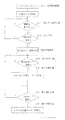
- the driving support method of the present embodiment includes a removal detection step S1, a determination step S2, a first selection step S3, and a first switching step S4.
- the public road mode M1 is selected, and the process proceeds to the removal detection step S1.
- the public road mode M1 continues until the public road mode M1 is switched to the non-public road mode M2.
- the process when it is detected that the safety part or the equipment has been removed from the vehicle body, the process proceeds to a determination step S2.
- the removal detection step S1 is continued until the removal of the safety part or the equipment is detected.
- the determination step S2 it is determined that the motorcycle exists in the non-public road area by satisfying the determination condition 65 including the detection signal in the removal detection step S1, and the non-public road mode can be selected. If the determination condition 65 is not satisfied in the determination step S2, the process returns to the removal detection step S1.
- the non-public road mode selectable state is a state in which selection from the public road mode M1 to the non-public road mode M2 is possible, and the process proceeds to the first selection step S3.
- a selection screen for the non-public road mode M2 is displayed on the meter unit 9, and the switching operation to the non-public road mode M2 is enabled.
- the meter unit 9 displays that the public road mode M1 is selected.
- the process proceeds to the first switching step S4, and the first selection step S3 is continued until the switching operation is performed.
- the anti-lock brake system ABS is switched to non-operation in response to the selection of the non-public road mode M2 in the first selection step S3.
- the anti-lock brake system ABS remains in the public road mode M1 except when the non-public road mode M2 is selected in the first selection step S3.
- the anti-lock brake system ABS is switched to the non-public road mode M2, and the selected mode is displayed on the meter unit 9, and the process proceeds to the second selection step S5.
- the process proceeds to the second switching step S6.
- the antilock brake system ABS is switched to the public road mode M1
- the selected mode is displayed on the meter unit 9, and the process returns to the first selection step S3.
- the anti-lock brake system ABS can be deactivated by the driver selecting the non-public road mode M2 in the non-public road region. Convenience is improved. In addition, the non-public road mode M2 cannot be selected unless the vehicle is present in the area determined as the non-public road area, and the antilock brake system ABS can be prevented from being undesirably released.
- the selection means 55 includes a mode switch 46 that can be selected by the driver while the vehicle is ready to travel. Thereby, since the non-public road mode M2 can be easily selected without disassembling the vehicle, convenience is improved.
- the selection means 55 selects the anti-lock brake system ABS in the public road mode M1, so even if the driving operation is ended in the non-public road mode M2 last time, When the next driving operation is resumed, it starts from the public road mode M1. Therefore, it is possible to prevent the anti-lock brake system ABS from being inoperative when traveling on a public road.
- the meter unit 9 displays that the public road mode M1 and the non-public road mode M2 can be selected, and has been selected as the non-public road mode M2. In this case, it is displayed that the non-public road mode M2 is being selected. Thereby, since it can be visually confirmed that the non-public road mode M2 can be selected, the convenience can be further improved, and the driver can be urged to be in the non-public road mode M2.
- the travel control means 57 determines the selection of the non-public road mode M2 by operating the mode changeover switch 46 that selects the travel mode (travel mode) during public road travel, there is no need to provide a separate switch as the selection means 55.
- traveling control means 57 determines the selection of the non-public road mode M2 by performing a plurality of switch operations, it is possible to prevent the non-public road mode M2 from being selected due to an erroneous operation by the driver.
- the judging means 64 judges the non-public road area by removing the safety parts of the motorcycle or the equipment including the same. In this way, it is necessary when traveling on the public road area, and when traveling on the non-public road area, it is possible to determine that it is present in the non-public road area by removing unnecessary safety parts or equipment including this.
- the vehicle can be changed to non-public road driving without any special operation. Specifically, the anti-lock brake system can be disabled during non-public road driving. This further improves convenience.
- the removal detection means 66 detects the removal of the equipment by a detection signal from the motion detection means 68 mounted on the vehicle body in order to detect the operation of the electrical component. Thereby, it is not necessary to provide a separate sensor as the removal detecting means 66, and an increase in the number of parts can be suppressed.
- the removal of the equipment can be detected by a signal from the sensor 70 that detects the removal of the equipment.
- the control device 69A of the first modified example further includes second non-public road area detecting means 72 for detecting that the vehicle exists in the non-public road area other than the removal of the parts.
- the detection signal from the public road area detection means 72 is included.
- the second non-public road area detection means 72 is an apparatus that can determine that the vehicle exists in the non-public road area using, for example, a means for detecting the current position of the vehicle such as GPS and map information stored in advance. . Transmission of the signal from the non-public road area detection means 72 may be wired or wireless.
- erroneous detection can be prevented by setting the signal from the removal detection means 66 and the signal from the non-public road area detection means 72 as the determination condition 65A.
- a motorcycle is equipped with components that are used only in the non-public road area.
- attachment detection means 74 for detecting this, and the determination condition 65B includes a detection signal from the attachment detection means 74.
- Parts used only in the non-public road area are, for example, a circuit control unit, a circuit authentication key, and a bib plate.
- the attachment detection unit 74 outputs a signal indicating a non-public road area.
- the motorcycle is changed to non-public road traveling due to erroneous detection by setting the signal from the removal detection means 66 and the signal from the attachment detection means 74 as the determination condition 65B. Can be prevented.
- the present invention is not limited to the above embodiment, and various additions, changes, or deletions are possible without departing from the gist of the present invention.
- the anti-lock brake system ABS is used as the driving support device.
- the present invention is not limited to this, and can be applied to general control in which some driving intervention control is performed in response to the driver's operation.
- the driving assistance device may be a traction control, an electronically controlled suspension, an output restriction, or the like that prevents the tire from slipping when starting and accelerating.
- the driving support device is configured to suppress the degree of driving intervention in the non-public road mode compared to the public road mode.
- the light emitting parts such as the direction indicators 32 and 38, the brake lamp 34, and the position lamp may not be turned on. Thereby, when trying to drive on a public road by mistake in the non-public road mode, the driver is made aware of this error.
- the detection line L2 is provided separately from the power supply line L1 shown in FIG. 4, and these lines L1 and L2 are connected to the operation detection means 68. However, the operation is performed without providing the detection line L2. Only the power supply line L1 may be connected to the detection means 68.
- the determination unit 64 and the selection unit 55 are included in the engine control unit ECU. However, the determination unit 64 and the selection unit 55 are not limited thereto, and may be included in the meter unit 9, for example.
- the public road mode M1 is selected when the main switch 52 is turned on. However, the public road mode M1 may be selected at the start of the operation of driving the engine E from the stop state. When the end of travel is determined, such as when the main switch 52 is turned off, the public road mode M1 may be selected as the mode for the next operation start. Further, the selected mode may be set to continue while the engine E is rotating. Furthermore, after the non-public road mode M1 is selected by the selection means 55 and the vehicle starts to travel, the vehicle may return to the public road mode M1 when the traveling stop state has elapsed for a predetermined time.
- the non-public road mode M1 may be configured so that one can be selected from a plurality of options as well as one stage that does not require driving support. Specifically, for example, a plurality of modes having different degrees of driving assistance may be prepared, and in a non-public road area, one of a plurality of modes may be selected by the driver's selection. Thereby, the driving assistance according to the driver's preference can be selected only in the non-public road area.
- the mode of the driving support device is changed to the driver. May be selectable. In that case, for example, even in a public road, the effect of the above-described embodiment can be achieved even in a region that is exceptionally handled as a non-public road. Further, the present invention can be applied to the case where the mode selection is invalidated on either the highway or the non-highway. Furthermore, when there is an area (country, area) where the installation of a driving assistance device is obliged on a public road, the mode of the driving assistance device may be selectable in an area other than such an area.
- the mode of the driving support device can be selected only when it is determined that a vehicle is present in the non-public road area, but the reverse operation may be performed. That is, when it is determined that a vehicle is present in the area where the installation of the driving support device is required, the selection of the mode of the driving support device is invalid or impossible, and the predetermined mode (public road mode) of the driving support device is set. You may make it perform.
- the driver in the boarding state can select the mode of the driving support device, but may be configured to be selectable by the driver in the getting off state.
- a mode switch may be provided in the accessory case or provided below the seat.
- a device capable of detecting the position of the vehicle such as GPS
- a non-public road code indicating that it is a non-public road area is stored in advance, and the code transmitted from outside the vehicle is compared with the stored non-public road code to determine that it is a non-public road area.
- Such a non-public road code may be encrypted, and may be received by either wired or wireless.
- the switch part of the selection means 55 is not limited to the mode changeover switch 46, and may be a switch provided in the meter unit 9, for example.
- the motorcycle has been described in the above embodiment, the present invention can also be applied to vehicles other than motorcycles. Therefore, such a thing is also included in the scope of the present invention.
Abstract
Priority Applications (4)
| Application Number | Priority Date | Filing Date | Title |
|---|---|---|---|
| PCT/JP2014/050221 WO2015104817A1 (fr) | 2014-01-09 | 2014-01-09 | Dispositif de commande de véhicule |
| JP2015556676A JP6178868B2 (ja) | 2014-01-09 | 2014-01-09 | 車両の制御装置 |
| EP14878093.5A EP3093199B1 (fr) | 2014-01-09 | 2014-01-09 | Dispositif de commande de véhicule |
| US15/202,453 US9637097B2 (en) | 2014-01-09 | 2016-07-05 | Vehicle control device |
Applications Claiming Priority (1)
| Application Number | Priority Date | Filing Date | Title |
|---|---|---|---|
| PCT/JP2014/050221 WO2015104817A1 (fr) | 2014-01-09 | 2014-01-09 | Dispositif de commande de véhicule |
Related Child Applications (1)
| Application Number | Title | Priority Date | Filing Date |
|---|---|---|---|
| US15/202,453 Continuation US9637097B2 (en) | 2014-01-09 | 2016-07-05 | Vehicle control device |
Publications (1)
| Publication Number | Publication Date |
|---|---|
| WO2015104817A1 true WO2015104817A1 (fr) | 2015-07-16 |
Family
ID=53523667
Family Applications (1)
| Application Number | Title | Priority Date | Filing Date |
|---|---|---|---|
| PCT/JP2014/050221 WO2015104817A1 (fr) | 2014-01-09 | 2014-01-09 | Dispositif de commande de véhicule |
Country Status (4)
| Country | Link |
|---|---|
| US (1) | US9637097B2 (fr) |
| EP (1) | EP3093199B1 (fr) |
| JP (1) | JP6178868B2 (fr) |
| WO (1) | WO2015104817A1 (fr) |
Cited By (2)
| Publication number | Priority date | Publication date | Assignee | Title |
|---|---|---|---|---|
| JP2018103688A (ja) * | 2016-12-22 | 2018-07-05 | 株式会社シマノ | 自転車用表示装置 |
| JP2019181997A (ja) * | 2018-04-02 | 2019-10-24 | 本田技研工業株式会社 | 車両の制御システム |
Families Citing this family (1)
| Publication number | Priority date | Publication date | Assignee | Title |
|---|---|---|---|---|
| JP6736596B2 (ja) | 2018-03-16 | 2020-08-05 | 本田技研工業株式会社 | 車両 |
Citations (4)
| Publication number | Priority date | Publication date | Assignee | Title |
|---|---|---|---|---|
| JPH0569848A (ja) * | 1991-09-11 | 1993-03-23 | Toyota Motor Corp | 車両運動制御装置 |
| JP2013028294A (ja) | 2011-07-29 | 2013-02-07 | Kawasaki Heavy Ind Ltd | 乗物用制御装置、該制御装置を備えた乗物及びその制御方法 |
| JP2013028279A (ja) * | 2011-07-28 | 2013-02-07 | Kawasaki Heavy Ind Ltd | 鞍乗り型の乗り物の制御装置および制御方法 |
| JP2013086632A (ja) * | 2011-10-17 | 2013-05-13 | Toyota Motor Corp | 車両制御装置 |
Family Cites Families (9)
| Publication number | Priority date | Publication date | Assignee | Title |
|---|---|---|---|---|
| SE521017C2 (sv) * | 2002-01-11 | 2003-09-23 | Saab Automobile | Fordonstyrsystem och metod för styrning av detsamma samt förargränssnitt med instrumentbräda |
| JP2007522981A (ja) * | 2004-02-20 | 2007-08-16 | シャープ株式会社 | 状況検出表示システム、状況検出表示方法、状況検出表示システム制御プログラム、および当該プログラムを記録した記録媒体 |
| JP2005306179A (ja) * | 2004-04-21 | 2005-11-04 | Toyota Motor Corp | 車両の制御装置 |
| US20070050193A1 (en) * | 2005-08-24 | 2007-03-01 | Larson Gerald L | Fuel use categorization for fuel tax reporting on commercial vehicles |
| JP5104134B2 (ja) * | 2007-09-04 | 2012-12-19 | 日産自動車株式会社 | 機能制限解除装置及び車両 |
| DE102009015415B4 (de) * | 2009-03-27 | 2017-05-11 | Bayerische Motoren Werke Aktiengesellschaft | Verfahren zur Auswahl verschiedener Fahrmodi sowie Fahrzeug, insbesondere Motorrad mit einer Elektronik, die in verschiedene Fahrmodi umschaltbar ist |
| JP5656677B2 (ja) * | 2011-02-14 | 2015-01-21 | 本田技研工業株式会社 | 自動二輪車用ブレーキ装置 |
| US20130311075A1 (en) * | 2012-05-18 | 2013-11-21 | Continental Automotive Systems, Inc. | Motorcycle and helmet providing advance driver assistance |
| WO2015039132A1 (fr) * | 2013-09-16 | 2015-03-19 | Decordova Daniel | Véhicules multimodaux pouvant se déplacer légalement dans différentes catégories |
-
2014
- 2014-01-09 JP JP2015556676A patent/JP6178868B2/ja active Active
- 2014-01-09 EP EP14878093.5A patent/EP3093199B1/fr active Active
- 2014-01-09 WO PCT/JP2014/050221 patent/WO2015104817A1/fr active Application Filing
-
2016
- 2016-07-05 US US15/202,453 patent/US9637097B2/en active Active
Patent Citations (4)
| Publication number | Priority date | Publication date | Assignee | Title |
|---|---|---|---|---|
| JPH0569848A (ja) * | 1991-09-11 | 1993-03-23 | Toyota Motor Corp | 車両運動制御装置 |
| JP2013028279A (ja) * | 2011-07-28 | 2013-02-07 | Kawasaki Heavy Ind Ltd | 鞍乗り型の乗り物の制御装置および制御方法 |
| JP2013028294A (ja) | 2011-07-29 | 2013-02-07 | Kawasaki Heavy Ind Ltd | 乗物用制御装置、該制御装置を備えた乗物及びその制御方法 |
| JP2013086632A (ja) * | 2011-10-17 | 2013-05-13 | Toyota Motor Corp | 車両制御装置 |
Cited By (3)
| Publication number | Priority date | Publication date | Assignee | Title |
|---|---|---|---|---|
| JP2018103688A (ja) * | 2016-12-22 | 2018-07-05 | 株式会社シマノ | 自転車用表示装置 |
| US10597106B2 (en) | 2016-12-22 | 2020-03-24 | Shimano Inc. | Bicycle display device |
| JP2019181997A (ja) * | 2018-04-02 | 2019-10-24 | 本田技研工業株式会社 | 車両の制御システム |
Also Published As
| Publication number | Publication date |
|---|---|
| US9637097B2 (en) | 2017-05-02 |
| EP3093199A4 (fr) | 2017-10-18 |
| JPWO2015104817A1 (ja) | 2017-03-23 |
| EP3093199B1 (fr) | 2018-11-28 |
| US20160311415A1 (en) | 2016-10-27 |
| EP3093199A1 (fr) | 2016-11-16 |
| JP6178868B2 (ja) | 2017-08-09 |
Similar Documents
| Publication | Publication Date | Title |
|---|---|---|
| JP6375310B2 (ja) | 車両およびその運転支援方法 | |
| JP5962319B2 (ja) | 車両制御装置 | |
| JP6332416B2 (ja) | 車両制御装置 | |
| KR20160002891A (ko) | 차량 구동력 제어 유닛, 제어 시스템, 제어 방법 및 차량 | |
| JP6178868B2 (ja) | 車両の制御装置 | |
| JP2010143542A (ja) | 電動パーキングブレーキシステム | |
| JP2019016000A (ja) | 運転支援装置 | |
| US9132771B2 (en) | Turn signal canceling device for a laterally tilting vehicle | |
| US9002577B2 (en) | Turn signal cancelling device for vehicle | |
| JP7100014B2 (ja) | 非常灯の電子制御を備えるモータサイクル | |
| CN109808595B (zh) | 车辆报警方法、装置、系统和车辆 | |
| JP6178583B2 (ja) | 直進旋回判定装置 | |
| TWI822660B (zh) | 用於兩輪車輛的停車輔助系統以及其的控制方法 | |
| KR20170119487A (ko) | 차량 및 차량의 제어 방법 | |
| JP2009214754A (ja) | 運転支援装置 | |
| US20230365212A1 (en) | Straddle type vehicle, method for controlling the same, control apparatus, and storage medium | |
| JP7199148B2 (ja) | 車両の前車発進警報装置 | |
| JP5640927B2 (ja) | ライト制御システムおよびライト | |
| US20240013660A1 (en) | Control device, warning control method, and non-transitory computer-readable storage medium | |
| WO2022195999A1 (fr) | Dispositif de klaxon automatique pour motocyclette | |
| JP2007307932A (ja) | 車両制御装置 | |
| JP4625718B2 (ja) | 車両センサモニタ装置 | |
| KR20220021925A (ko) | 운전자 보조 시스템 및 운전자 보조 방법 | |
| JP2023093987A (ja) | 制御装置及び制御方法 | |
| JP6097191B2 (ja) | アイドルストップ制御装置 |
Legal Events
| Date | Code | Title | Description |
|---|---|---|---|
| 121 | Ep: the epo has been informed by wipo that ep was designated in this application |
Ref document number: 14878093 Country of ref document: EP Kind code of ref document: A1 |
|
| ENP | Entry into the national phase |
Ref document number: 2015556676 Country of ref document: JP Kind code of ref document: A |
|
| NENP | Non-entry into the national phase |
Ref country code: DE |
|
| REEP | Request for entry into the european phase |
Ref document number: 2014878093 Country of ref document: EP |
|
| WWE | Wipo information: entry into national phase |
Ref document number: 2014878093 Country of ref document: EP |