WO2015093492A1 - Élément de fixation - Google Patents
Élément de fixation Download PDFInfo
- Publication number
- WO2015093492A1 WO2015093492A1 PCT/JP2014/083300 JP2014083300W WO2015093492A1 WO 2015093492 A1 WO2015093492 A1 WO 2015093492A1 JP 2014083300 W JP2014083300 W JP 2014083300W WO 2015093492 A1 WO2015093492 A1 WO 2015093492A1
- Authority
- WO
- WIPO (PCT)
- Prior art keywords
- piercing
- substrate
- fastener
- catch
- piercing needle
- Prior art date
Links
Images


Classifications
-
- A—HUMAN NECESSITIES
- A44—HABERDASHERY; JEWELLERY
- A44B—BUTTONS, PINS, BUCKLES, SLIDE FASTENERS, OR THE LIKE
- A44B17/00—Press-button or snap fasteners
- A44B17/0052—Press-button fasteners consisting of four parts
-
- A—HUMAN NECESSITIES
- A41—WEARING APPAREL
- A41F—GARMENT FASTENINGS; SUSPENDERS
- A41F1/00—Fastening devices specially adapted for garments
- A41F1/002—Magnetic fastening devices
-
- A—HUMAN NECESSITIES
- A44—HABERDASHERY; JEWELLERY
- A44B—BUTTONS, PINS, BUCKLES, SLIDE FASTENERS, OR THE LIKE
- A44B17/00—Press-button or snap fasteners
- A44B17/0005—Fastening of press-button fasteners
-
- A—HUMAN NECESSITIES
- A44—HABERDASHERY; JEWELLERY
- A44D—INDEXING SCHEME RELATING TO BUTTONS, PINS, BUCKLES OR SLIDE FASTENERS, AND TO JEWELLERY, BRACELETS OR OTHER PERSONAL ADORNMENTS
- A44D2203/00—Fastening by use of magnets
-
- Y—GENERAL TAGGING OF NEW TECHNOLOGICAL DEVELOPMENTS; GENERAL TAGGING OF CROSS-SECTIONAL TECHNOLOGIES SPANNING OVER SEVERAL SECTIONS OF THE IPC; TECHNICAL SUBJECTS COVERED BY FORMER USPC CROSS-REFERENCE ART COLLECTIONS [XRACs] AND DIGESTS
- Y10—TECHNICAL SUBJECTS COVERED BY FORMER USPC
- Y10T—TECHNICAL SUBJECTS COVERED BY FORMER US CLASSIFICATION
- Y10T24/00—Buckles, buttons, clasps, etc.
- Y10T24/19—Necktie fastener
- Y10T24/1959—Magnetic, adhesive, or snap type fastener connects tie to shirt
-
- Y—GENERAL TAGGING OF NEW TECHNOLOGICAL DEVELOPMENTS; GENERAL TAGGING OF CROSS-SECTIONAL TECHNOLOGIES SPANNING OVER SEVERAL SECTIONS OF THE IPC; TECHNICAL SUBJECTS COVERED BY FORMER USPC CROSS-REFERENCE ART COLLECTIONS [XRACs] AND DIGESTS
- Y10—TECHNICAL SUBJECTS COVERED BY FORMER USPC
- Y10T—TECHNICAL SUBJECTS COVERED BY FORMER US CLASSIFICATION
- Y10T24/00—Buckles, buttons, clasps, etc.
- Y10T24/32—Buckles, buttons, clasps, etc. having magnetic fastener
-
- Y—GENERAL TAGGING OF NEW TECHNOLOGICAL DEVELOPMENTS; GENERAL TAGGING OF CROSS-SECTIONAL TECHNOLOGIES SPANNING OVER SEVERAL SECTIONS OF THE IPC; TECHNICAL SUBJECTS COVERED BY FORMER USPC CROSS-REFERENCE ART COLLECTIONS [XRACs] AND DIGESTS
- Y10—TECHNICAL SUBJECTS COVERED BY FORMER USPC
- Y10T—TECHNICAL SUBJECTS COVERED BY FORMER US CLASSIFICATION
- Y10T24/00—Buckles, buttons, clasps, etc.
- Y10T24/34—Combined diverse multipart fasteners
- Y10T24/3467—Pin
- Y10T24/3468—Pin and pin
-
- Y—GENERAL TAGGING OF NEW TECHNOLOGICAL DEVELOPMENTS; GENERAL TAGGING OF CROSS-SECTIONAL TECHNOLOGIES SPANNING OVER SEVERAL SECTIONS OF THE IPC; TECHNICAL SUBJECTS COVERED BY FORMER USPC CROSS-REFERENCE ART COLLECTIONS [XRACs] AND DIGESTS
- Y10—TECHNICAL SUBJECTS COVERED BY FORMER USPC
- Y10T—TECHNICAL SUBJECTS COVERED BY FORMER US CLASSIFICATION
- Y10T24/00—Buckles, buttons, clasps, etc.
- Y10T24/46—Pin or separate essential cooperating device therefor
Definitions
- the present invention relates to a fastener for freely opening and closing an opening of clothing, a bag or the like using a piercing needle with a piercing catch.
- the fastener of the present invention is A pair of substrates provided with a piercing needle for penetrating a face material such as a cloth; A piercing catch provided corresponding to the pair of substrates and sandwiching the piercing needle; An attaching / detaching means provided on the pair of substrates and capable of attaching / detaching the substrates while setting a force required for the attachment / detachment to be smaller than a force of the piercing catch holding the piercing needle; It is characterized by having.
- the attaching / detaching means is preferably composed of a male hook provided on one substrate and a female hook provided on the other substrate.
- the attaching / detaching means is composed of a magnet provided on one substrate and a magnet or a magnetic body provided on the other substrate.
- a protrusion may be provided on the one substrate, and a recess corresponding to the protrusion may be provided on the other substrate.
- the fastener of the present invention comprises a pair of substrates provided with a piercing needle for penetrating a face material such as cloth.
- a piercing catch provided corresponding to the pair of substrates and sandwiching the piercing needle;
- the first detachable piece is provided on the outer periphery of the pierced catch corresponding to one substrate, and the second detachable piece having the shape surrounding the pierced catch is provided on the other substrate, and the first detachable piece and the second detachable piece are magnets or magnets Mounting / removal means comprised of a combination of It is characterized by having.
- the fastener of the present invention A pair of substrates provided with a piercing needle for penetrating a face material such as a cloth; A piercing catch provided corresponding to the pair of substrates and sandwiching the piercing needle; The first detachable piece is provided on the outer periphery of the pierced catch corresponding to one of the substrates, and the second detachable piece having the shape surrounding the pierced catch is provided on the other substrate and provided on one of the first detachable and second detachable pieces.
- a detachable means comprising a male hook and a female hook provided on the other side; It is characterized by having.
- a fastener is a substrate provided with a piercing needle for penetrating a face material such as cloth.
- a piercing catch provided corresponding to the substrate and sandwiching the piercing needle;
- a magnet provided on the substrate; It is characterized by having.
- the piercing catch or the substrate is provided with attachment / detachment means for accessories.
- piercing catch with the cap which covers at least attachment or detachment operation part of a piercing needle.
- FIG. 1 It is sectional drawing which shows the structure of the fastener (A type) which concerns on Embodiment 1 of this invention. It is explanatory drawing which shows the state which attached the fastener shown in FIG. 1 to opening parts, such as a handbag. It is a partially broken side view which shows the fastener (B type) which concerns on Embodiment 2.
- FIG. It is explanatory drawing of the use condition of the fastener shown in FIG. It is a partially broken side view which shows the structure of the fastener (C type) which concerns on Embodiment 3 of this invention. It is explanatory drawing which shows the use condition of the fastener shown in FIG. It is a partially broken side view which shows the fastener (B type) which concerns on Embodiment 4.
- FIG. 14 is a partially broken side view showing a piercing catch in which the structure of piercing catch 3 according to the first to third embodiments is modified.
- FIG. 21 is a cross-sectional view showing a piercing catch in which the structure of the piercing catch according to the fourth and fifth embodiments is changed. It is explanatory drawing which shows the state which attached the accessory to the fastener shown in FIG. FIG.
- FIG. 21 is a cross-sectional view showing a pierce catch according to a seventh embodiment. It is sectional drawing which shows the fastener which concerns on Embodiment 8. FIG. It is sectional drawing which shows the fastener which concerns on Embodiment 9. It is explanatory drawing which shows the use condition of the fastener shown in FIG. It is sectional drawing which shows the fastener which concerns on Embodiment 10. FIG. It is explanatory drawing which shows the use condition of the fastener shown in FIG. It is sectional drawing which shows the fastener which concerns on Embodiment 11. FIG. It is explanatory drawing which shows the use condition of the fastener shown in FIG. FIG.
- FIG. 21 is a cross-sectional view showing a fastener according to a twelfth embodiment. It is explanatory drawing which shows the use condition of the fastener shown in FIG. It is explanatory drawing which shows the use aspect of the fastener shown in the said Embodiment 1-12. It is explanatory drawing which shows the example which applied the fastener to the tote bag. It is explanatory drawing which shows the example which applied the fastener to a muffler and a stall. It is explanatory drawing which shows the example in the case of using only one fastening member of a fastener. It is explanatory drawing which shows the use condition of the fastening member shown in FIG. FIG. 33 is an explanatory drawing showing how to use the tenth to twelfth embodiments.
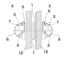
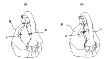
- FIG. 1 is a partially broken side view showing the structure of the fastener (A type) of the present invention.
- the fastener comprises a pair of fasteners a, b.
- These fastening members a and b each include a substrate 1 having a piercing needle 2 on the back side, and a piercing catch 3 for holding the piercing needle 2.
- the piercing catch 3 includes a bottom surface member 5 having the through hole 4 of the piercing needle 2, a pinching piece 7 (catch member) extending from the bottom face member 5 and pinching the tip of the piercing needle 2, the bottom face member 5 and pinching And a housing 6 for housing the piece 7 therein.
- the substrate 1 is preferably planar. This is to hold the cloth between the snap pins 3 when attaching the cloth. From such a point of view, it is preferable that the surface on the substrate 1 side of the piercing catch 3 be also formed flat.
- a female hook 9 which constitutes a detachable portion is provided on the surface of the base plate 1 of the fastening member a.
- a male hook 8 constituting an attaching / detaching portion is provided on the surface of the base plate 1 of the fastening member b.
- the piercing catch 3 may have a known structure other than the above configuration.
- FIG. 2 is an explanatory view showing a state in which the fastener shown in FIG. 1 is attached to an opening of a handbag or the like.
- the piercing needle 2 provided on the substrate 1 of each of the fastening members a and b is removed from the piercing catch 3.
- each piercing needle 2 is penetrated through the opposing cloth 10 of the portion of the opening to be locked, and then the tip end of the piercing needle 2 is passed through the through hole 4 of the piercing catch 3 to fasten it.
- the members a and b are fixed to the fabric 10.
- the fastening members a and b are respectively provided on the facing surface of the fabric 10 in the opening.
- the opening can be closed. Opening the male hook 8 and the female hook 9 can be opened.
- the strength of the spring of the female hook 9 makes the mating strength of the male hook 8 and the female hook 9 different.
- the strength of the spring of the female hook 9 is large, when removing the male hook 8 from the female hook 9, the piercing catch 3 is detached from the piercing needle 2 before the female hook 9 and the male hook 8 are detached. That is, when the earring catch 3 is pinched and pulled, if the force for removing the male hook 8 from the female hook 9 is larger than the force for the earring catch 3 to hold the piercing needle 2, the piercing needle 2 is pulled out from the piercing catch 3 , Can not open the opening. Therefore, in the present invention, the strength of the spring of the female hook 9 is smaller than the force required for the piercing catch 3 to hold the piercing needle 2 when the male hook 8 and the female hook 9 are attached and detached. To be set.
- this fastener attachment is possible anywhere without processing cloth or leather. Also, you can use it freely because it is free to remove it. Moreover, since it is attachment by a piercing needle, almost no trace is left on the cloth. And by attaching fasteners to existing products, a simple cloth becomes a scarf, scarf, cloak etc with fasteners that can be stopped in front of the neck. Furthermore, since it can be easily attached to any position, it can be opened and closed at any desired position of the tote bag, for example. Moreover, a plurality of binding positions can be set by using a plurality of fasteners.
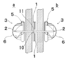
- FIG. 3 is a partially broken side view showing a fastener (B type) according to a second embodiment.
- FIG. 4 is an explanatory view of a usage state of the fastener shown in FIG.
- symbol is attached
- the fastener according to the second embodiment is characterized in that the substrate 1 of the fastener shown in FIG. 3 is formed of a magnet.
- the substrates 1 can be easily attached and detached.
- one of the substrates 1 may be formed of a magnet and the other may be formed of a ferromagnetic material. Further, the magnet may be provided on the entire surface or a part of the substrate 1 (not shown).
- the thickness of the substrate 1 is preferably such that no space is generated between the fabric 10 and the fabric 10.
- the planar shape of the substrate 1 may be various shapes such as a circle, a square, and a rectangle.
- the number of piercing needles 2 extending from the substrate 1 may be one or more depending on the shape of the substrate 1. When a plurality of piercing needles 2 are used, a plurality of piercing catches corresponding to the respective piercing needles 2 are used.
- this fastener As described above, it is possible to attach anywhere without using cloth or leather. Also, you can use it freely because it is free to remove it. Moreover, since it is attachment by a piercing needle, almost no trace is left on the cloth. And by attaching fasteners to existing products, a simple cloth will become a scarf, scarf, cloak etc with fasteners that can be stopped in front of the neck. Furthermore, since it can be easily attached to any position, it can be opened and closed at any desired position of the tote bag, for example. Moreover, a plurality of binding positions can be set by using a plurality of fasteners. In particular, since the magnet can be attached and detached, opening and closing is easy. By changing the magnet force, it is also possible to obtain an optimal opening / closing force according to the application.
- FIG. 5 is a partially broken side view showing a structure of a fastener (C type) according to a third embodiment of the present invention.
- This fastener is obtained by replacing one of the substrates 1 of the B-type fastener of Embodiment 2 with a magnetic material from a magnet.
- the third embodiment is characterized in that the concave portion 11 is formed on one of the mounting and demounting surfaces of the substrate 1 and the convex portion 10 fitted to the concave portion 11 is formed on the other.
- FIG. 6 is an explanatory view showing a usage state of the fastener shown in FIG.
- the piercing needle 2 and the piercing catch 3 are used to attach the substrate 1 of the fastening members a and b to the fabric 10 of the opening such as clothing. Since the substrate 1 is respectively formed of a magnet and a magnetic material, it can be reliably attracted by the mutual attraction action, and the opening can be closed.
- substrate 1 are fitted, board
- the shape and number of the convex part 10 and the recessed part 11 can be arbitrarily determined according to a condition.
- the convex part 10 and the recessed part 11 were provided in the center of the board
- the convex portion 10 and the concave portion 11 may be provided in a circular donut shape, and the surfaces of the substrate 1 may be firmly adsorbed at the center. Further, by providing the convex portion 10 and the concave portion 11 at an arbitrary angle in the circumferential direction of the substrate 1, the substrates 1 do not rotate and are firmly adsorbed (all are not shown for the modified example).
- this fastener As described above, it is possible to attach anywhere without using cloth or leather. Also, you can use it freely because it is free to remove it. Moreover, since it is attachment by a piercing needle, almost no trace is left on the cloth. And by attaching fasteners to existing products, a simple cloth will become a scarf, scarf, cloak etc with fasteners that can be stopped in front of the neck. Furthermore, since it can be easily attached to any position, it can be opened and closed at any desired position of the tote bag, for example. Moreover, a plurality of binding positions can be set by using a plurality of fasteners. In particular, since the magnet can be attached and detached, opening and closing is easy. By changing the magnet force, it is also possible to obtain an optimal opening / closing force according to the application.
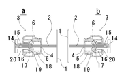
- FIG. 7 is a partially broken side view showing a fastener (B type) according to a fourth embodiment.
- This fastener is characterized in that it has a ball catch structure different from the piercing catch 3 of the fastener of the second and third embodiments.
- the piercing catch 3 of the fastener is disposed through the housing 6 provided with the insertion port 4 for inserting the piercing needle 2 in the bottom surface member 5 and the ceiling portion of the housing 6 and pinched with a finger to move in the axial direction And a tubular body 18 fixed in the housing 6.
- the housing 6 is shaped to store and protect the internal structure and to make the appearance design beautiful.
- the knob member 15 has a through hole 14 through which the piercing needle 2 passes at the center in the axial direction.
- a washer-like pressing member 16 is provided at the end of the knob member 15.
- a flange is formed on the other end of the knob member 15 and is easy to pick with a finger.
- a spring 20 is disposed between the pressing member 16 and the housing 6, and the pressing member 16 is biased toward the bottom member 5 by the spring 20.
- the cylindrical body 18 has, at its end, a truncated conical inclined wall 19 whose diameter increases toward the ceiling (to the right in the figure).
- the cylindrical body 18 may be integrated with the housing 6.
- a plurality of spheres 17 for holding the piercing needle 2 are disposed between the inclined wall 19 and the pressing member 16. Two or more spheres 17 are used.
- FIG. 8 is an explanatory view showing a usage state of the fastener shown in FIG.
- the flange at the end of the knob 15 is pinched and pulled, the restriction of the sphere 17 by the pressing member 16 and the inclined wall 19 is released.
- the piercing needle 2 is inserted from the insertion port 4 of the housing 6, the piercing needle 2 is inserted into the through hole 14 of the pinching member 15 through between the opposing spheres 17.
- the piercing catch 3 is not detached when the opening is opened and closed. For this reason, the piercing catch 3 does not come off from the cloth material even in hard use such as a tote bag. On the other hand, the piercing catch 3 can be easily removed by pulling the pick member 15.
- this fastener as described above, it is possible to attach anywhere without using cloth or leather without any processing. Also, you can use it freely because it is free to remove it. Moreover, since it is attachment by a piercing needle, almost no trace is left on the cloth. And by attaching fasteners to existing products, a simple cloth will become a scarf, scarf, cloak etc with fasteners that can be stopped in front of the neck. Furthermore, since it can be easily attached to any position, it can be opened and closed at any desired position of the tote bag, for example. Moreover, a plurality of binding positions can be set by using a plurality of fasteners. In particular, since the magnet can be attached and detached, opening and closing is easy. By changing the magnet force, it is also possible to obtain an optimal opening / closing force according to the application.
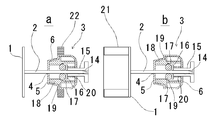
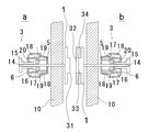
- FIG. 9 is a partially broken side view showing a structure of a fastener (D type) according to a fifth embodiment.
- FIG. 10 is an explanatory view showing a usage state of the fastener shown in FIG.
- One fastening member a of this fastener is provided with a ring-shaped magnet 22 (first detachable piece) in the direction perpendicular to the formation direction of the through hole 14 in the vicinity of the center of the outer periphery of the housing 6 And the piercing needle 2 is extended from the center thereof.
- the substrate 1 may be nonmagnetic or magnetic.
- the ring-shaped magnet 22 has a donut shape and obtains necessary magnetic force depending on the diameter and thickness.
- the ring-shaped magnet 22 may be covered by a cover (not shown). Furthermore, the shape in the vicinity of the center of the outer periphery of the housing 6 may be extended in the vertical direction with respect to the through hole 14 and may be incorporated therein (not shown). In addition, as described later, the ring-shaped magnet 22 may be larger than the housing because it is only necessary for the piercing catch 3 to be hidden by the donut-shaped member 21.
- the internal structure of the piercing catch 3 is the same as that of the piercing catch 3 shown in the fourth embodiment, so the description thereof is omitted and the same components are denoted by the same reference numerals.
- the fastening member b is configured such that a donut-like member 21 (second detachable piece) is provided on the surface of the flat substrate 1.
- the piercing needle 2 extends from the center of the substrate 1.
- the piercing needle 2 is held by the piercing catch 3.
- the donut-like member 21 is formed into a cylindrical shape from a metal plate of magnetic material.
- the donut-like member 21 may be solid or hollow (not shown).
- the shape and area of the end face of the donut-shaped member 21 are preferably substantially the same as the shape and area of the ring-shaped magnet 22 in terms of both function and appearance.
- the donut-like member 21 may be configured integrally with the substrate 1.
- the axial length of the donut-like member 21 (left and right direction in the figure, length direction of the piercing needle 2) is greater than the length from the end face of the ring-shaped magnet 22 to the flange of the other end of the pinching member 15 Do.
- the casing 6 of the piercing catch 3 can be accommodated by the donut-like member 21.
- the shape is free. More preferably, the inner shape of the donut-shaped member 21 is substantially the same as the outer shape of the housing 6. As shown in FIG.
- the donut-like member 21 is naturally attached to the casing 6.
- the ring magnet 22 can be attached to the ring magnet 22.
- the donut-like member 21 is attracted to the ring-like magnet 22 so that the donut-like member 21 of the fastening member b is placed on the housing 6 of the fastening member a.
- the ring-shaped magnet 22 is provided outside the housing 6 so that the housing 6 projects in one direction of the ring-shaped magnet 22, and the housing 6 enters the inside of the donut-shaped member 21 in the suction state.
- the fastening members a and b are attracted to each other at the correct position, so that the opening can be prevented from opening, and the donut member 21 and the ring magnet 22 are displaced in the surface direction in the adsorbed state. Can be prevented.
- the base plate 1 of one of the fastening members by making the base plate 1 of one of the fastening members a flat, it becomes less likely to cause a problem in which articles, fingers and the like are caught as compared with the case where the piercing catch 3 protrudes outward. Furthermore, the decorative material 23 such as a gem can be easily provided on the substrate 1.
- the type shown in the fourth embodiment is used as the piercing catch 3
- any type shown in the first to third embodiments may be used as the piercing catch 3.
- the donut-like member 21 may be formed of a magnet.
- the ring-shaped magnet 22 is comprised by a magnetic body, when making the donut-shaped member 21 into a magnet.
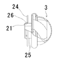
- FIG. 11 is a partially broken side view showing the piercing catch in which the structure of the piercing catch 3 according to the first to third embodiments is changed.
- FIG. 12 is a cross-sectional view showing a pierced catch in which the structure of the pierced catch according to the fourth and fifth embodiments is changed.
- a cylindrical body 25 is provided below the bottom surface member 5, and a snap pin groove 21 is provided in the vicinity of the end of the outer peripheral wall.
- the cylindrical body 25 is provided with a disc-like stop ring 24 whose center is open.
- the snap pin 26 is formed by bending a bar-like metal into a C-shape, and can be fitted into the snap pin groove 21 by spreading. The snap pin 26 prevents the retaining ring 24 from falling off the cylinder 25.
- a space for fitting the decorative material 23 is formed between the retaining ring 24 and the housing 6.
- a flange portion is formed so as to protrude laterally on the outer wall intermediate surface of the housing 6, and a cylindrical portion 25 is provided below the flange portion.
- a snap pin groove 21 is provided near the end of the cylindrical portion 25, a snap pin groove 21 is provided.
- the snap pin 26 is formed by bending a bar-like metal into a C-shape, and can be fitted into the snap pin groove 21 by spreading. The snap pin 26 prevents the retaining ring 24 from falling off the cylindrical portion.
- a space for fitting the decorative material 23 is formed between the retaining ring 24 and the flange portion.
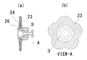
- FIG. 13 is an explanatory view showing a state in which the accessory is attached to the fastener shown in FIG.
- the accessory 23 which consists of a plane board of the shape of a flower is shown.
- the thickness of the accessory 23 is smaller than the distance between the flange and the retaining ring.
- the snap pin 26 is removed and the retaining ring is pulled out of the cylindrical part.
- the accessory 23 having an opening at the center is inserted.
- the cylindrical portion is inserted into an opening provided at the center of the accessory 23.
- the retaining ring 24 is attached to the cylindrical portion, the snap pin is fitted into the snap pin groove 21, and the accessory 23 is fixed by the retaining ring 26 and the flange.
- the shape of the accessory 23 may be any shape as long as it can be inserted into a cylindrical body or a cylindrical portion.
- the accessory 23 can be attached in the same procedure as the above (illustration omitted).
- the snap pin 26 is removed, the retaining ring 24 is removed from the cylindrical body 25, and the accessory 23 having an opening at its center is inserted.
- the cylindrical body 25 is inserted into an opening provided at the center of the shape of the flower, and the retaining ring 24 is attached to the cylindrical body 25.
- the snap pin 26 is fitted into the snap pin groove 21 and the accessory 23 is fixed by the retaining ring 26 and the bottom member.
- the accessory 23 can be easily attached to the piercing catch 3. Moreover, if it has a hole through which the cylindrical member 25 can be inserted, many accessories 23 can be attached.
- FIG. 14 is a cross-sectional view showing a piercing catch according to the seventh embodiment.
- This piercing catch is characterized in that the piercing catch of the fastener shown in the fourth to sixth embodiments is provided with a cap 30 for preventing malfunction.
- a screw is formed on the outer surface of the piercing catch housing.
- the cap 30 has a screw corresponding to the screw of the housing formed in the vicinity of the inner end, and can be attached to the housing so as to cover the knob member which is the attaching / detaching operation portion of the piercing needle 2.
- the entire shape of the cap 30 may be a hemispherical shape or a butterfly-shaped easy-to-pick shape.
- FIG. 15 is a cross-sectional view showing a fastener according to an eighth embodiment.
- the convex portion 31 is provided on the surface of the substrate 1 of the fastening member a
- the recess 32 is provided on the surface of the substrate 1 of the fastening member b.
- the recess is formed of a protrusion formed on the substrate 1 and a donut-shaped magnet thicker than the protrusion fitted around the protrusion.
- the piercing catch 3 has the same structure as that shown in the fourth to seventh embodiments, but may be the one shown in the first to third embodiments (not shown).
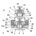
- FIG. 16 is a cross-sectional view showing a fastener according to a ninth embodiment.
- FIG. 17 is an explanatory view showing a usage state of the fastener shown in FIG.
- This fastener consists of a pair of fastening members a and b.
- These fastening members a and b each include a substrate 1 having a piercing needle 2 on the back side, and a piercing catch 3 for holding the piercing needle 2. Since the piercing catch 3 is the same as the piercing catch 3 shown in the fourth embodiment, the description thereof is omitted, and the same components are denoted by the same reference numerals.
- the hook member 6a is formed at a substantially central position on the outer periphery of the fastening member a in the axial direction (vertical direction in the drawing, length direction of the through hole 14) of the housing 6 of the piercing catch 3.
- a ring member 51 is provided on the retaining member b side of the weir 6a. A part of the end face of the ring member 51 abuts on the weir 6a.
- On the inner surface of the ring member 51 a snap pin groove 53 for holding the snap pin 52 is provided on the inner surface of the ring member 51.
- the snap pin 52 is formed by bending a bar-like metal into a C-shape, and can be fitted into the snap pin groove 53 by spreading.
- An inner weir 51 a is formed on the side of the weir 6 a of the ring member 51 inward, and abuts against the weir 6 a of the housing 6.
- the inner flange 51a abuts on an end face of the later-described cylindrical member 60 of the fastening member b to restrict the position.
- the outer surface of the ring member 51 is a simple cylindrical curved surface in FIG. Further, a fixing plate 54 is provided for the ring member 51.
- the fixing plate 54 is disk-shaped, and a hole 55 is formed at the center of the fixing plate 54 into which the housing 6 is fitted, and a shallow annular recess 56 is formed around the hole 55 for holding the collar 6a of the housing. Further, the end face of the fixing plate 54 abuts on the end face of the ring member 51 and is joined by adhesion or welding.
- the housing 6 is held by the ring member 51 and the fixing plate 54 It is fixed. In this state, the insertion port 4 of the housing 6 is exposed from the fixing plate 54, and the pick member 15 is exposed inside the ring member 51.
- the snap pin 52 is located near the ceiling of the housing 6.
- a cylindrical member 60 is provided on the side opposite to the piercing needle 2.
- the cylindrical member 60 may be integrally molded with the substrate 1.
- the axial length (vertical direction in the figure, the longitudinal direction of the piercing needle 2) and the diameter of the cylindrical member 60 are set so as to be able to accommodate the housing 6 and the picking member 15 of the fastening member a.
- the outer diameter of the cylindrical member 60 is slightly smaller than the inner diameter of the ring member 51.
- the thickness of the cylindrical member 60 is in the range in which it can enter the gap between the inner surface of the ring member 51 of the fastening member a and the outer surface of the housing 6.
- the outer periphery of the cylindrical member 60 is provided with a projection 61 that engages with the snap pin 52.
- the protrusion 61 has a substantially semicircular shape, and is in smooth contact with the snap pin 52 so that the snap pin 52 can be easily pushed and spread.
- the dimensions are determined such that the end edge of the cylindrical member 60 abuts on the inner ring 51 a of the ring member 51 in a state where the projection 61 is engaged with the snap pin 52.
- the fastening members a and b are respectively attached to the opening of the handbag or the like (not shown).
- the operation of the piercing catch 3 is the same as that of the fourth embodiment.
- the cylindrical member 60 of the fastening member b is inserted into the ring member 51 of the fastening member a and inserted so as to cover the housing 6.
- the protrusion 61 of the cylindrical member 60 pushes and spreads the snap pin 52 to go over the snap pin 52, and the end thereof abuts on the inner weir 51a. In this state, the cylindrical member 60 is held inside the ring member 51 by the inner hook 51 a and the snap pin 52.
- the housing 6 enters the inside of the cylindrical member 60.
- the appearance of the fastener is controlled by the ring member 51 and the tubular member 60 and the internal structure is concealed, so that the clasp becomes clean and beautiful.
- it since it has a clean appearance and does not catch, even if it protrudes inside such as a handbag etc., a thing will not be caught.
- the base plate 1 of one of the fastening members a flat, it becomes less likely to cause a problem in which articles, fingers and the like are caught as compared with the case where the piercing catch 3 protrudes outward. Furthermore, a decorative material such as a gem can be easily provided on the substrate 1.
- any type shown in the first to third embodiments may be used as the piercing catch 3. .
- the cloth or leather can be attached anywhere without large processing.
- it is easy to use because it is free to remove.
- it since it is attachment by a piercing needle, almost no trace is left on the cloth.
- fasteners to existing products, it becomes a scarf, scarf, cloak, etc. where a simple cloth can be stopped in front of the neck.
- it since it can be easily attached to any position, it can be opened and closed at any desired position of the tote bag, for example.
- a plurality of binding positions can be set by using a plurality of fasteners.
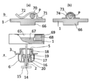
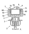
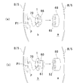
- FIG. 18 is a cross-sectional view showing a fastener according to a tenth embodiment.
- FIG.19 and FIG.29 (a) is explanatory drawing which shows the use condition of the fastener shown in FIG.
- the concave portion 65 is provided on the surface of the substrate 1 of the fastening member a
- the convex portion 66 is provided on the surface of the substrate 1 of the fastening member b.
- the base 1 of the fastening member a is provided with a circular projection 67 at the center in plan view.
- a donut-shaped magnet 68 thicker than the protrusion 67 is provided around the periphery.
- the substrate 1 and the magnet 68 are covered by a cover 69.
- the cover 69 is made of a thin material and is provided from the outer periphery of the substrate 1 to the outer periphery of the magnet 68 and the end face of the magnet 68 on the retaining member b side, and is provided obliquely from the inner end of the magnet 68 to the inside.
- the end of the cover 69 leads to the corner of the protrusion 67 of the substrate 1.
- the recessed part 65 is formed in the center vicinity of the whole fastening member a.
- a hook 70 is provided on the surface opposite to the surface on which the convex portion 66 of the fastening member b is provided, as shown in FIG.
- the hook 70 is a metal molded body, and one end 71 is welded to the substrate 1 and is curved away from the surface of the substrate 1 at the center to curve outward and abut against the surface of the substrate 1 again, and the other end is bent back It has become. Thereby, the wire of the safety pin P can be inserted into the hook 70 from the other end 72 of the warp.
- (b) shows an example in which a through hole is provided instead of the hook 70.
- the through hole 73 is formed by welding the both ends of the half cylindrical member 74 to the substrate 1.
- the wire of the safety pin P is inserted into the through hole 73.
- this fastener locks the fastening member b to the safety pin P attached to the bag B or a part of the muffler S.
- the safety pin P is attached, for example, to a part of the opening of the handbag, and at that time, the hook 70 is inserted into the wire P1 which has come out on the back surface to lock the fastening member b.
- the fastening member a is fixed at a position corresponding to the part of the handbag by sticking the piercing needle 2 and attaching the piercing catch 3 from the back surface thereof.
- the concave portion 65 of the fastening member a is fitted to the convex portion 66 of the fastening member b, and the substrate 1 and the substrate 1 are adsorbed by the magnetic force of the magnet 68.
- the opening of the handbag can be opened and closed.
- the cloth or leather can be attached anywhere without large processing.
- the safety pin P can be used for mounting, versatility is further enhanced. Furthermore, since it is free to remove, it is easy to use. Moreover, since it is attachment by the piercing needle
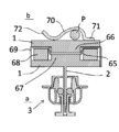
- FIG. 20 is a cross-sectional view showing a fastener according to an eleventh embodiment.
- 21 and 29 (b) are explanatory views showing the usage state of the fastener shown in FIG.
- the fastening member a of the fastener is provided with a ring member 80 on the substrate 1.
- a snap pin groove 53 for holding the snap pin 52 is provided on the inner surface of the ring member 80.
- the snap pin 52 is formed by bending a bar-like metal into a C-shape, and can be fitted into the snap pin groove 53 by spreading.
- the outer surface of the ring member 80 is a simple cylindrical curved surface in FIG.
- a cylindrical member 60 is provided on the substrate 1 of the fastening member b.
- the cylindrical member 60 may be integrally molded with the substrate 1.
- the axial length (vertical direction in the drawing) of the cylindrical member 60 is substantially the same as the axial length (vertical direction in the drawing) of the ring member 80.
- the outer diameter of the cylindrical member 60 is slightly smaller than the inner diameter of the ring member 80.
- the outer periphery of the cylindrical member 60 is provided with a projection 61 that engages with the snap pin 52.
- the protrusion 61 has a substantially semicircular shape, and is in smooth contact with the snap pin 52 so that the snap pin 52 can be easily pushed and spread. Each dimension is determined so that the end edge of the cylindrical member 60 abuts on the surface of the base plate 1 of the fastening member a in a state where the projection 61 is engaged with the snap pin 52.
- the fastening member a is attached to the opening of the handbag B (not shown) when used.
- the operation of the piercing catch 3 is the same as that of the fourth embodiment.
- the fastening member b is engaged with the safety pin P.
- the safety pin P is attached to the corresponding position of the opening of the handbag, and at that time, the hook 70 is inserted into the wire P1 which comes out on the back surface, and the fastening member b is locked.
- the cylindrical member 60 of the fastening member b is inserted into the ring member 80 of the fastening member a.
- the protrusion 61 of the cylindrical member 60 pushes and spreads the snap pin 52 to get over the snap pin 52, and the end thereof abuts on the substrate 1. In this state, the tubular member 60 is held inside the ring member 80 by the snap pin 52.
- the ring member 80 and the tubular member 60 fit tightly with each other to make the appearance of the fastener clear and beautiful. In addition, since it has a clean appearance and does not catch, even if it protrudes inside such as a handbag etc., a thing will not be caught.
- the type shown in the fourth embodiment is used as the piercing catch 3
- any type shown in the first to third embodiments may be used as the piercing catch 3. .
- the cloth or leather can be attached anywhere without large processing.
- it is easy to use because it is free to remove.
- the attachment is made by the piercing needle 2 and the safety pin P, almost no trace is left on the cloth.
- fasteners to existing products, it becomes a scarf, scarf, cloak, etc. where a simple cloth can be stopped in front of the neck.
- it can be easily attached to any position, it can be opened and closed at any desired position of the tote bag, for example.
- a plurality of binding positions can be set by using a plurality of fasteners.
- the closure with the accessory can be made.
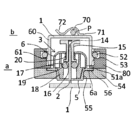
- FIG. 22 is a cross-sectional view showing a fastener according to a twelfth embodiment.
- FIG. 23 is an explanatory view showing a usage state of the fastener shown in FIG.
- a protrusion 61 engaged with the snap pin 52 is provided on the outer periphery of the cylindrical member 60.
- the fastening member a has the same structure as the fastening member b shown in the ninth embodiment, the same reference numeral is given to the same component.
- the external appearance of the fastener is such that the ring member and the tubular member 60 fit tightly with each other, resulting in a cleaner and more beautiful thing.
- the substrate 1 has no flange-like structure and has a clean appearance without being caught, even if it protrudes to the inside of a handbag or the like, no matter is caught.
- the type shown in the fourth embodiment is used as the piercing catch 3
- any type shown in the first to third embodiments may be used as the piercing catch 3. .
- the fastener according to the present invention can be used to pierce the piercing needle 2 on both sides of the opening without subjecting the opening of the clothing or bag to stitching or caulking with a button or metal fitting. Since it can be made to fix by the attached piercing catch after penetrating in any place of, it is easy to attach or detach. In addition, since the tip of the piercing needle 2 is included by the piercing catch 3, it is safe without causing the occurrence of a puncture and the like during handling. In addition, since it is detachable and portable, it can be used as a fastener for locking the opening when folding a hand-held blanket or the like and using it as a simple bag, so it is highly responsive. The same applies to the safety pin P type.
- FIG. 24 is an explanatory view showing a use mode of the fastener shown in the first to eleventh embodiments.
- This fastener secures the bedding to the double rings provided on both sides of the handle to form a handbag B.
- fastening members a and b are attached to the opening part of this handbag B.
- the mounting method is as described in the first to eleventh embodiments.
- the fastening members a and b are joined together to close the opening.
- FIG. 25 is an explanatory view showing an example in which a fastener is applied to a tote bag. Similarly, the fastening members a and b are attached to the opening of the tote bag T, and the fastening members a and b are joined together to close the opening.
- FIG. 26 is an explanatory view showing an example in which a fastener is applied to a muffler or a stall.
- fastening members a and b are attached to two places of the muffler S, and the muffler S is wound around the neck to fasten the fastening members a and b together. Thereby, the muffler S can be easily fixed around the neck.
- fastening members a and b are attached to two places of the stall S, and the stall S is fastened to the head with the fastening members a and b. This makes it easy to wear the stall S.
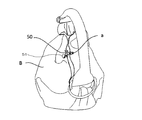
- FIG. 27 is an explanatory view showing an example in which only one fastening member of the fastener is used.
- FIG. 28 is an explanatory view showing a usage state of the fastening member shown in FIG.
- the fastening member a has a configuration in which the magnet 1 a is provided on the surface of the substrate 1.
- the fastening member a is attached to the opening of the handbag B or the like by the same method as described above.
- the magnetic material clip 50 is sandwiched at a position facing the fastening member a. Since the clip 50 is a magnetic body, it is attracted to the magnet 1 a of the fastening member.
- An accessory 51 may be attached to one surface of the clip 50.
- the shape of the clip 50 is not limited to that shown in FIG. 27 as long as it has a surface to which the magnet 1a can be attracted.
Abstract
Priority Applications (5)
| Application Number | Priority Date | Filing Date | Title |
|---|---|---|---|
| JP2015553559A JP6101887B2 (ja) | 2013-12-16 | 2014-12-16 | 留め具 |
| US14/902,321 US9795193B2 (en) | 2013-12-16 | 2014-12-16 | Fastening tool |
| EP14872822.3A EP3085264B1 (fr) | 2013-12-16 | 2014-12-16 | Élément de fixation |
| KR1020157036508A KR101830491B1 (ko) | 2013-12-16 | 2014-12-16 | 고정구 |
| CN201480038056.4A CN105358004B (zh) | 2013-12-16 | 2014-12-16 | 卡固件 |
Applications Claiming Priority (2)
| Application Number | Priority Date | Filing Date | Title |
|---|---|---|---|
| JP2013259159 | 2013-12-16 | ||
| JP2013-259159 | 2013-12-16 |
Publications (1)
| Publication Number | Publication Date |
|---|---|
| WO2015093492A1 true WO2015093492A1 (fr) | 2015-06-25 |
Family
ID=53402837
Family Applications (1)
| Application Number | Title | Priority Date | Filing Date |
|---|---|---|---|
| PCT/JP2014/083300 WO2015093492A1 (fr) | 2013-12-16 | 2014-12-16 | Élément de fixation |
Country Status (6)
| Country | Link |
|---|---|
| US (1) | US9795193B2 (fr) |
| EP (1) | EP3085264B1 (fr) |
| JP (3) | JP6101887B2 (fr) |
| KR (1) | KR101830491B1 (fr) |
| CN (1) | CN105358004B (fr) |
| WO (1) | WO2015093492A1 (fr) |
Families Citing this family (10)
| Publication number | Priority date | Publication date | Assignee | Title |
|---|---|---|---|---|
| US9618193B1 (en) * | 2016-05-12 | 2017-04-11 | Jeremy William Lord | Garment docking device for attaching personal devices |
| US10512292B2 (en) * | 2016-09-08 | 2019-12-24 | Tina Curtis | Accessory fastener device and method |
| AU2018295575B2 (en) * | 2017-07-07 | 2023-08-17 | Zavargê Pty Ltd | Improvements in bedding including push-pin securing assembly |
| CN109289133B (zh) * | 2017-07-24 | 2021-10-08 | 霍尼韦尔国际公司 | 用于面罩的一体式带构造 |
| US10849393B2 (en) * | 2017-08-28 | 2020-12-01 | Gabrielle Rae Shapiro | Earring backing, earrings and earring display devices |
| US10918176B1 (en) * | 2019-10-08 | 2021-02-16 | Michael Roth | Magnetic backing for collector pin |
| WO2022145461A1 (fr) * | 2020-12-28 | 2022-07-07 | 株式会社ワイズグレース | Attache de broche et accessoire personnel utilisant celle-ci |
| USD1021685S1 (en) * | 2021-10-28 | 2024-04-09 | Chin-Sung Huang | Positioning pin of a seat belt buckle |
| US20230380553A1 (en) * | 2022-05-26 | 2023-11-30 | Aubrey Singleton | Magnetic pin attachment device |
| KR102585165B1 (ko) * | 2023-04-03 | 2023-10-05 | 두영이노베이션 주식회사 | 개인용품 소지용 홀더 조립체 |
Citations (8)
| Publication number | Priority date | Publication date | Assignee | Title |
|---|---|---|---|---|
| JPS5929912U (ja) * | 1982-08-20 | 1984-02-24 | 武田 精 | スナツプフアスナ−用リベツト体 |
| JPS63243312A (ja) * | 1987-03-27 | 1988-10-11 | 株式会社 エルプラニングシステム | ホツク釦の取付方法とホツク釦 |
| JPS6440008A (en) * | 1987-08-06 | 1989-02-10 | Tamao Morita | Clasp |
| JPH0613517U (ja) * | 1992-07-21 | 1994-02-22 | 株式会社徳力本店 | 装身具の係止装置 |
| JPH06165706A (ja) * | 1992-11-30 | 1994-06-14 | Yoshida Kogyo Kk <Ykk> | スナップボタンの雌体およびその取着用カシメ型 |
| JP3070576U (ja) * | 2000-01-28 | 2000-08-04 | 良夫 松原 | 留め機能を有するボタン |
| JP2002065317A (ja) * | 2000-09-01 | 2002-03-05 | Kiyohara Kk | スナップボタン |
| JP2008110196A (ja) | 2006-10-04 | 2008-05-15 | U-Oak Sha:Kk | 取っ手 |
Family Cites Families (13)
| Publication number | Priority date | Publication date | Assignee | Title |
|---|---|---|---|---|
| US1336692A (en) * | 1919-11-03 | 1920-04-13 | Forman Joseph | Garment-fastener |
| US1438889A (en) * | 1921-01-15 | 1922-12-12 | Bates Edith May | Pin-attached snap fastener |
| JP2576220B2 (ja) * | 1989-02-27 | 1997-01-29 | 日立プラント建設株式会社 | 可撓管サポート装置 |
| CN1065735C (zh) * | 1994-02-28 | 2001-05-16 | 株式会社应用技术研究所 | 磁闭合装置 |
| CN1281663A (zh) * | 1999-01-27 | 2001-01-31 | 株工会社M&K横谷 | 固定搭扣 |
| WO2000076700A1 (fr) * | 1999-06-16 | 2000-12-21 | Bonnie Roche | Dispositifs de presentation, accessoires et procedes s'y rapportant |
| ES2237336B1 (es) * | 2004-12-14 | 2006-06-01 | Industrias Sinteticas Catalanas, S.L. | Dispositivo de union de prendas y articulo textil que incluye dicho dispositivo. |
| US7356882B1 (en) * | 2005-11-22 | 2008-04-15 | Guadagno Iv James V | Magnetic flower attachment device |
| US20080005873A1 (en) * | 2006-07-06 | 2008-01-10 | Helen Of Troy Limited | Magnetic pushpin |
| CN201375102Y (zh) * | 2009-04-02 | 2010-01-06 | 东莞达基钮扣制品有限公司 | 纽扣 |
| US8052365B2 (en) * | 2009-04-15 | 2011-11-08 | Enlisted Design, LLC | Magnetic safety pushpin |
| US20110047759A1 (en) * | 2009-08-25 | 2011-03-03 | Romag Fasteners Inc. | Closures with magnetic and mechanical snap fastening and method of making the same |
| CN102415655A (zh) * | 2011-11-24 | 2012-04-18 | 罗日梅 | 一种免缝按扣 |
-
2014
- 2014-12-16 JP JP2015553559A patent/JP6101887B2/ja active Active
- 2014-12-16 KR KR1020157036508A patent/KR101830491B1/ko active IP Right Grant
- 2014-12-16 US US14/902,321 patent/US9795193B2/en active Active
- 2014-12-16 WO PCT/JP2014/083300 patent/WO2015093492A1/fr active Application Filing
- 2014-12-16 CN CN201480038056.4A patent/CN105358004B/zh not_active Expired - Fee Related
- 2014-12-16 EP EP14872822.3A patent/EP3085264B1/fr active Active
-
2016
- 2016-08-24 JP JP2016163810A patent/JP2016193343A/ja active Pending
- 2016-08-24 JP JP2016163809A patent/JP6578480B2/ja active Active
Patent Citations (8)
| Publication number | Priority date | Publication date | Assignee | Title |
|---|---|---|---|---|
| JPS5929912U (ja) * | 1982-08-20 | 1984-02-24 | 武田 精 | スナツプフアスナ−用リベツト体 |
| JPS63243312A (ja) * | 1987-03-27 | 1988-10-11 | 株式会社 エルプラニングシステム | ホツク釦の取付方法とホツク釦 |
| JPS6440008A (en) * | 1987-08-06 | 1989-02-10 | Tamao Morita | Clasp |
| JPH0613517U (ja) * | 1992-07-21 | 1994-02-22 | 株式会社徳力本店 | 装身具の係止装置 |
| JPH06165706A (ja) * | 1992-11-30 | 1994-06-14 | Yoshida Kogyo Kk <Ykk> | スナップボタンの雌体およびその取着用カシメ型 |
| JP3070576U (ja) * | 2000-01-28 | 2000-08-04 | 良夫 松原 | 留め機能を有するボタン |
| JP2002065317A (ja) * | 2000-09-01 | 2002-03-05 | Kiyohara Kk | スナップボタン |
| JP2008110196A (ja) | 2006-10-04 | 2008-05-15 | U-Oak Sha:Kk | 取っ手 |
Also Published As
| Publication number | Publication date |
|---|---|
| JP2017018612A (ja) | 2017-01-26 |
| CN105358004A (zh) | 2016-02-24 |
| CN105358004B (zh) | 2018-10-19 |
| EP3085264A1 (fr) | 2016-10-26 |
| EP3085264B1 (fr) | 2019-07-31 |
| JPWO2015093492A1 (ja) | 2017-03-16 |
| EP3085264A4 (fr) | 2017-09-27 |
| US20160374438A1 (en) | 2016-12-29 |
| JP6578480B2 (ja) | 2019-09-25 |
| JP6101887B2 (ja) | 2017-03-29 |
| US9795193B2 (en) | 2017-10-24 |
| KR20160013989A (ko) | 2016-02-05 |
| JP2016193343A (ja) | 2016-11-17 |
| KR101830491B1 (ko) | 2018-02-20 |
Similar Documents
| Publication | Publication Date | Title |
|---|---|---|
| WO2015093492A1 (fr) | Élément de fixation | |
| US8650723B2 (en) | Non-rotatable snap fasteners | |
| US8667650B1 (en) | Decorative magnetic cufflink conversion device | |
| US7784158B2 (en) | Fabric fastener with twist lock clip | |
| JP6326529B2 (ja) | 襟固定器具 | |
| US10064441B1 (en) | Locking button system | |
| US10149517B2 (en) | Connector mechanism for attaching accessory and accessory therefor | |
| JP6804829B2 (ja) | ボタン留め、ボタン外し力を差異化した雌部品を有するスナップ・ファスナ | |
| US20100242230A1 (en) | Clothing fasteners | |
| CN110973781B (zh) | 饰品用紧固部件、饰品用紧固件以及饰品 | |
| JP3196484U (ja) | 留め具 | |
| JP3196993U (ja) | 留め具 | |
| JP3216018U (ja) | 留め具 | |
| JP3138948U (ja) | 仮施錠型留め具 | |
| TWI461159B (zh) | 卡扣具 | |
| JP2012095786A (ja) | 係合具 | |
| JP3177973U (ja) | 生地挟着用保持具 | |
| JP4099724B2 (ja) | ブレスレット | |
| KR101507279B1 (ko) | 장신구 고정용 기구 | |
| JPS6214804A (ja) | カフスボタン | |
| JP3206841U (ja) | ピンズ回動防止具 | |
| JP2023165403A (ja) | 衣服用装飾体 | |
| US20120260489A1 (en) | Button repair system and method | |
| JP2015061699A (ja) | 生地挟着用保持具 | |
| JP3131399U (ja) | カフスボタン |
Legal Events
| Date | Code | Title | Description |
|---|---|---|---|
| WWE | Wipo information: entry into national phase |
Ref document number: 201480038056.4 Country of ref document: CN |
|
| 121 | Ep: the epo has been informed by wipo that ep was designated in this application |
Ref document number: 14872822 Country of ref document: EP Kind code of ref document: A1 |
|
| ENP | Entry into the national phase |
Ref document number: 2015553559 Country of ref document: JP Kind code of ref document: A |
|
| REEP | Request for entry into the european phase |
Ref document number: 2014872822 Country of ref document: EP |
|
| WWE | Wipo information: entry into national phase |
Ref document number: 2014872822 Country of ref document: EP |
|
| ENP | Entry into the national phase |
Ref document number: 20157036508 Country of ref document: KR Kind code of ref document: A |
|
| WWE | Wipo information: entry into national phase |
Ref document number: 14902321 Country of ref document: US |
|
| NENP | Non-entry into the national phase |
Ref country code: DE |