WO2015087734A1 - ナトリウムイオン電池用電極合材、及びその製造方法並びにナトリウム全固体電池 - Google Patents
ナトリウムイオン電池用電極合材、及びその製造方法並びにナトリウム全固体電池 Download PDFInfo
- Publication number
- WO2015087734A1 WO2015087734A1 PCT/JP2014/081773 JP2014081773W WO2015087734A1 WO 2015087734 A1 WO2015087734 A1 WO 2015087734A1 JP 2014081773 W JP2014081773 W JP 2014081773W WO 2015087734 A1 WO2015087734 A1 WO 2015087734A1
- Authority
- WO
- WIPO (PCT)
- Prior art keywords
- crystal
- sodium ion
- electrode mixture
- active material
- powder
- Prior art date
- Legal status (The legal status is an assumption and is not a legal conclusion. Google has not performed a legal analysis and makes no representation as to the accuracy of the status listed.)
- Ceased
Links
Images

Classifications
-
- H—ELECTRICITY
- H01—ELECTRIC ELEMENTS
- H01M—PROCESSES OR MEANS, e.g. BATTERIES, FOR THE DIRECT CONVERSION OF CHEMICAL ENERGY INTO ELECTRICAL ENERGY
- H01M4/00—Electrodes
- H01M4/02—Electrodes composed of, or comprising, active material
- H01M4/36—Selection of substances as active materials, active masses, active liquids
- H01M4/58—Selection of substances as active materials, active masses, active liquids of inorganic compounds other than oxides or hydroxides, e.g. sulfides, selenides, tellurides, halogenides or LiCoFy; of polyanionic structures, e.g. phosphates, silicates or borates
- H01M4/5825—Oxygenated metallic salts or polyanionic structures, e.g. borates, phosphates, silicates, olivines
-
- C—CHEMISTRY; METALLURGY
- C03—GLASS; MINERAL OR SLAG WOOL
- C03C—CHEMICAL COMPOSITION OF GLASSES, GLAZES OR VITREOUS ENAMELS; SURFACE TREATMENT OF GLASS; SURFACE TREATMENT OF FIBRES OR FILAMENTS MADE FROM GLASS, MINERALS OR SLAGS; JOINING GLASS TO GLASS OR OTHER MATERIALS
- C03C3/00—Glass compositions
- C03C3/12—Silica-free oxide glass compositions
- C03C3/14—Silica-free oxide glass compositions containing boron
-
- H—ELECTRICITY
- H01—ELECTRIC ELEMENTS
- H01B—CABLES; CONDUCTORS; INSULATORS; SELECTION OF MATERIALS FOR THEIR CONDUCTIVE, INSULATING OR DIELECTRIC PROPERTIES
- H01B1/00—Conductors or conductive bodies characterised by the conductive materials; Selection of materials as conductors
- H01B1/06—Conductors or conductive bodies characterised by the conductive materials; Selection of materials as conductors mainly consisting of other non-metallic substances
- H01B1/08—Conductors or conductive bodies characterised by the conductive materials; Selection of materials as conductors mainly consisting of other non-metallic substances oxides
-
- H—ELECTRICITY
- H01—ELECTRIC ELEMENTS
- H01M—PROCESSES OR MEANS, e.g. BATTERIES, FOR THE DIRECT CONVERSION OF CHEMICAL ENERGY INTO ELECTRICAL ENERGY
- H01M10/00—Secondary cells; Manufacture thereof
- H01M10/05—Accumulators with non-aqueous electrolyte
- H01M10/054—Accumulators with insertion or intercalation of metals other than lithium, e.g. with magnesium or aluminium
-
- H—ELECTRICITY
- H01—ELECTRIC ELEMENTS
- H01M—PROCESSES OR MEANS, e.g. BATTERIES, FOR THE DIRECT CONVERSION OF CHEMICAL ENERGY INTO ELECTRICAL ENERGY
- H01M10/00—Secondary cells; Manufacture thereof
- H01M10/05—Accumulators with non-aqueous electrolyte
- H01M10/056—Accumulators with non-aqueous electrolyte characterised by the materials used as electrolytes, e.g. mixed inorganic/organic electrolytes
- H01M10/0561—Accumulators with non-aqueous electrolyte characterised by the materials used as electrolytes, e.g. mixed inorganic/organic electrolytes the electrolyte being constituted of inorganic materials only
- H01M10/0562—Solid materials
-
- H—ELECTRICITY
- H01—ELECTRIC ELEMENTS
- H01M—PROCESSES OR MEANS, e.g. BATTERIES, FOR THE DIRECT CONVERSION OF CHEMICAL ENERGY INTO ELECTRICAL ENERGY
- H01M4/00—Electrodes
- H01M4/02—Electrodes composed of, or comprising, active material
- H01M4/04—Processes of manufacture in general
- H01M4/0471—Processes of manufacture in general involving thermal treatment, e.g. firing, sintering, backing particulate active material, thermal decomposition, pyrolysis
-
- H—ELECTRICITY
- H01—ELECTRIC ELEMENTS
- H01M—PROCESSES OR MEANS, e.g. BATTERIES, FOR THE DIRECT CONVERSION OF CHEMICAL ENERGY INTO ELECTRICAL ENERGY
- H01M4/00—Electrodes
- H01M4/02—Electrodes composed of, or comprising, active material
- H01M4/13—Electrodes for accumulators with non-aqueous electrolyte, e.g. for lithium-accumulators; Processes of manufacture thereof
- H01M4/136—Electrodes based on inorganic compounds other than oxides or hydroxides, e.g. sulfides, selenides, tellurides, halogenides or LiCoFy
-
- H—ELECTRICITY
- H01—ELECTRIC ELEMENTS
- H01M—PROCESSES OR MEANS, e.g. BATTERIES, FOR THE DIRECT CONVERSION OF CHEMICAL ENERGY INTO ELECTRICAL ENERGY
- H01M4/00—Electrodes
- H01M4/02—Electrodes composed of, or comprising, active material
- H01M4/36—Selection of substances as active materials, active masses, active liquids
- H01M4/362—Composites
- H01M4/364—Composites as mixtures
-
- H—ELECTRICITY
- H01—ELECTRIC ELEMENTS
- H01M—PROCESSES OR MEANS, e.g. BATTERIES, FOR THE DIRECT CONVERSION OF CHEMICAL ENERGY INTO ELECTRICAL ENERGY
- H01M4/00—Electrodes
- H01M4/02—Electrodes composed of, or comprising, active material
- H01M4/62—Selection of inactive substances as ingredients for active masses, e.g. binders, fillers
-
- H—ELECTRICITY
- H01—ELECTRIC ELEMENTS
- H01M—PROCESSES OR MEANS, e.g. BATTERIES, FOR THE DIRECT CONVERSION OF CHEMICAL ENERGY INTO ELECTRICAL ENERGY
- H01M2300/00—Electrolytes
- H01M2300/0017—Non-aqueous electrolytes
- H01M2300/0065—Solid electrolytes
- H01M2300/0068—Solid electrolytes inorganic
- H01M2300/0071—Oxides
-
- Y—GENERAL TAGGING OF NEW TECHNOLOGICAL DEVELOPMENTS; GENERAL TAGGING OF CROSS-SECTIONAL TECHNOLOGIES SPANNING OVER SEVERAL SECTIONS OF THE IPC; TECHNICAL SUBJECTS COVERED BY FORMER USPC CROSS-REFERENCE ART COLLECTIONS [XRACs] AND DIGESTS
- Y02—TECHNOLOGIES OR APPLICATIONS FOR MITIGATION OR ADAPTATION AGAINST CLIMATE CHANGE
- Y02E—REDUCTION OF GREENHOUSE GAS [GHG] EMISSIONS, RELATED TO ENERGY GENERATION, TRANSMISSION OR DISTRIBUTION
- Y02E60/00—Enabling technologies; Technologies with a potential or indirect contribution to GHG emissions mitigation
- Y02E60/10—Energy storage using batteries
Definitions
- the present invention relates to a sodium ion battery electrode mixture used for portable electronic devices and electric vehicles, a method for producing the same, and a sodium all solid state battery.
- organic electrolytic solution is mainly used as an electrolyte in current electricity storage devices such as lithium ion secondary batteries.
- organic electrolytes exhibit high ionic conductivity, they are liquids and flammable, so there are concerns about risks such as leakage and ignition when used as power storage devices.
- an object of the present invention is to provide a sodium ion battery electrode mixture and a sodium all-solid battery that are dense, excellent in sodium ion conductivity, and capable of high output.
- the electrode mixture for a sodium ion secondary battery of the present invention is characterized by containing an active material crystal, a sodium ion conductive crystal and an amorphous phase.
- the active material crystal is Na, M (M is at least one transition metal element selected from Cr, Fe, Mn, Co and Ni), P and O. It is preferable to contain.
- the active material crystal is preferably a triclinic crystal belonging to the space group P1 or P-1.
- the active material crystals the general formula Na x M y P 2 O 7 (where x in 1.20 ⁇ x ⁇ 2.80, and y is 0.95 ⁇ y ⁇ 1.60) is expressed in It is preferable that it is a crystal.
- the active material crystal preferably contains at least one selected from Nb and Ti and O.
- the active material crystal contains Na and / or Li.
- the active material crystal is preferably an orthorhombic crystal, a hexagonal crystal, a cubic crystal, or a monoclinic crystal.
- the active material crystal is preferably a monoclinic crystal belonging to the space group P2 1 / m.
- the active material crystal is preferably at least one metal crystal selected from Sn, Bi and Sb.
- the sodium ion conductive crystal preferably contains at least one selected from Al, Y, Zr, Si and P, Na and O.
- the sodium ion conductive crystal is preferably a monoclinic crystal, a hexagonal crystal, or a trigonal crystal.
- the amorphous phase preferably contains at least one selected from P, B and Si, Na and O.
- the sodium all-solid battery of the present invention is characterized by using the electrode mixture for sodium ion secondary batteries as a positive electrode.
- the sodium all-solid battery of the present invention is characterized by using the electrode mixture for a sodium ion secondary battery as a negative electrode.
- the method for producing an electrode mixture for a sodium ion secondary battery of the present invention is characterized in that a raw material powder containing a crystalline glass powder is fired to form an amorphous phase.
- the present invention it is possible to provide a sodium ion battery electrode mixture and a sodium all-solid battery that are dense, excellent in sodium ion conductivity, and capable of high output.
- Electrode composite material for sodium ion secondary battery of the present invention is characterized by containing an active material crystal, a sodium ion conductive crystal and an amorphous phase. Since the electrode mixture for sodium ion secondary batteries contains an amorphous phase in addition to the active material crystal and the sodium ion conductive crystal, the amorphous phase is formed between the active material crystal and the sodium ion conductive crystal. It tends to be present at the interface, and the interface resistance between the active material crystal and the sodium ion conductive crystal that becomes the conduction path of sodium ion during charging and discharging of the sodium ion secondary battery is likely to decrease, and the charging of the sodium secondary battery Discharge capacity and battery voltage tend to be high.
- the electrode mixture contains an amorphous phase
- the interface between the electrode mixture and the sodium ion conductive solid electrolyte layer increases the adhesive strength due to the amorphous phase, The charge / discharge capacity and battery voltage of a sodium all-solid battery are likely to increase.
- the active material crystal acts as a positive electrode active material or a negative electrode active material, and can store and release sodium ions during charge and discharge.
- active material crystals that act as the positive electrode active material include layered sodium transition metal oxide crystals such as NaCrO 2 , Na 0.7 MnO 2 , NaFe 0.2 Mn 0.4 Ni 0.4 O 2, and Na 2 FeP 2.
- Examples thereof include sodium transition metal phosphate crystals.
- a crystal containing Na, M, P, and O is preferable because of its high capacity and excellent chemical stability.
- triclinic crystals belonging to the space group P1 or P1 particularly the general formula Na x M y P 2 O 7 (x in 1.20 ⁇ x ⁇ 2.80, and y is 0.95 ⁇ y ⁇ 1.60) is preferable because it has excellent cycle characteristics.
- Examples of the active material crystal that acts as the negative electrode active material include a crystal containing at least one selected from Nb and Ti and O, and at least one metal crystal selected from Sn, Bi, and Sb.
- a crystal containing at least one selected from Nb and Ti and O is preferable because of excellent cycle characteristics. Furthermore, when the crystal containing at least one selected from Nb and Ti and O contains Na and / or Li, the charge / discharge efficiency (ratio of the discharge capacity to the charge capacity) increases, and a high charge / discharge capacity is maintained. Is preferable.
- a crystal containing at least one selected from Nb and Ti and O is an orthorhombic crystal, a hexagonal crystal, a cubic crystal, or a monoclinic crystal, and particularly belongs to the space group P2 1 / m. Monoclinic crystals are more preferable because capacity is unlikely to decrease even when charged and discharged with a large current.
- NaTi 2 O 4 and the like As the orthorhombic crystal, NaTi 2 O 4 and the like, and as the hexagonal crystal, Na 2 TiO 3 , NaTi 8 O 13 , NaTiO 2 , LiNbO 3 , LiNbO 2 , Li 7 NbO 6 , LiNbO 2 , Li 2 Ti 3 O 7 and the like are cubic crystals such as Na 2 TiO 3 , NaNbO 3 , Li 4 Ti 5 O 12 , and Li 3 NbO 4 , and monoclinic crystals are Na 2 Ti 6 O.
- the crystal containing at least one selected from Nb and Ti and O preferably further contains at least one selected from B, Si, P and Ge. These components have an effect of facilitating the formation of an amorphous phase together with the active material crystal and improving sodium ion conductivity.
- At least one metal crystal selected from Sn, Bi and Sb, or glass containing at least one selected from Sn, Bi and Sb can be used. These are preferable because they have a high capacity and are unlikely to decrease in capacity even when charged and discharged with a large current.
- the sodium ion conductive crystal is a crystal that acts as a sodium ion conductive path between the active material crystal and the counter electrode, has excellent conductivity of sodium ions, and has high electronic insulation. . If there is no sodium ion conductive crystal, the sodium ion transfer resistance between the active material crystal and the counter electrode becomes very high, and the charge / discharge capacity and the battery voltage decrease.
- the sodium ion conductive crystal is preferably a crystal containing at least one selected from Al, Y, Zr, Si and P, Na and O.
- the sodium ion conductive crystal has a general formula Na s A1 t A2 u O v
- the sodium ion conductive crystal is preferably a NASICON crystal.
- NASICON crystals Na 3 Zr 2 Si 2 PO 12 , Na 3.2 Zr 1.3 Si 2.2 P 0.8 O 10.5 , Na 3 Zr 1.6 Ti 0.4 Si 2 PO 12 , Na 3 Hf 2 Si 2 PO 12 , Na 3.4 Zr 0.9 Hf 1.4 Al 0.6 Si 1.2 P 1.8 O 12 , Na 3 Zr 1.7 Nb 0.24 Si 2 PO 12 Na 3.6 Ti 0.2 Y 0.8 Si 2.8 O 9 , Na 3 Zr 1.88 Y 0.12 Si 2 PO 12 , Na 3.12 Zr 1.88 Y 0.12 Si 2 PO 12 , Na 3.6 Zr 0.13 Yb 1.67 Si 0.11 P 2.9 O 12 and the like are preferable, and Na 3.12 Zr 1.88 Y 0.12 Si 2 PO 12 is a sodium ion. Excellent conductivity Masui.
- the sodium ion conductive crystal is a monoclinic crystal, a hexagonal crystal, or a trigonal crystal because the conductivity of sodium ions is further increased.
- beta alumina is also preferable because of its excellent sodium ion conductivity.
- ⁇ ′′ alumina has higher sodium ion conductivity than ⁇ alumina, it is preferable to use ⁇ ′′ alumina alone or a mixture of ⁇ ′′ alumina and ⁇ alumina, and Li 2 O stabilized ⁇ ′′ alumina (Na 1. 7 Li 0.3 Al 10.7 O 17 ) or MgO stabilized ⁇ ′′ alumina ((Al 10.32 Mg 0.68 O 16 ) (Na 1.68 O)) is more preferred.
- Na 5 YSi 4 O 12 can be used as the sodium ion conductive solid electrolyte.
- the amorphous phase acts as a sodium ion conduction path at the crystal interface of the active material crystal or sodium ion conductive crystal, and conducts sodium ions in the electrode mixture. There is an effect of improving.
- the amorphous phase contains at least one selected from P, B, and Si, Na and O, because the conductivity and chemical durability of sodium ions are excellent.
- the electrode mixture preferably further contains a conductive additive.
- the conductive additive is a component added to achieve high capacity and high rate of the electrode mixture.
- Specific examples of the conductive assistant include highly conductive carbon black such as acetylene black and ketjen black, graphite, coke, and metal powder such as Ni powder, Cu powder, and Ag powder. Among them, it is preferable to use any one of highly conductive carbon black, Ni powder, and Cu powder that exhibits excellent conductivity when added in a very small amount.
- FIG. 1 is a schematic cross-sectional view showing an embodiment of an all solid state battery.
- a positive electrode 2 a sodium ion conductive solid electrolyte layer 3, and a negative electrode 4 are laminated in this order.
- the positive electrode 2 includes, in order from the sodium ion conductive solid electrolyte layer 3 side, a positive electrode mixture 5 and a positive electrode current collector 6 that collects the positive electrode mixture 5.
- the negative electrode 4 includes, in order from the sodium ion conductive solid electrolyte layer 3 side, a negative electrode mixture 7 and a negative electrode current collector 8 that collects the negative electrode mixture 7.
- the positive electrode mixture 5 or the negative electrode mixture 7 includes an amorphous phase
- the adhesive strength of the interface increases due to the amorphous phase, and the charge / discharge capacity and battery voltage tend to increase.
- an electrode active material crystal powder or an active material crystal precursor powder is prepared. Further, sodium ion conductive crystal powder or sodium ion conductive crystal precursor powder is prepared. These powders are obtained by preparing raw powders and using the obtained raw powders by chemical vapor phase synthesis processes such as melting processes, sol-gel processes, spraying solution mists into flames, mechanochemical processes, etc. It is done.
- the active material crystal precursor powder and the sodium ion conductive crystal precursor powder are crystalline glass powders (glass powders having a property of precipitating crystals by heat treatment).
- the average particle diameter D50 of the active material crystal powder and the active material crystal precursor powder is preferably 15 ⁇ m or less, more preferably 10 ⁇ m or less, and even more preferably 5 ⁇ m or less. If the average particle diameter D50 of the active material crystal powder and the active material crystal precursor powder is too large, the resistance of sodium ion diffusion tends to increase and the battery characteristics tend to be inferior. On the other hand, the lower limit of the average particle diameter D50 of the active material crystal powder and the active material crystal precursor powder is not particularly limited, but is actually 0.1 ⁇ m or more.
- the average particle diameter D50 of the sodium ion conductive crystal powder or sodium ion conductive crystal precursor powder is preferably 25 ⁇ m or less, more preferably 20 ⁇ m or less, and even more preferably 15 ⁇ m or less. If the average particle diameter D50 of the sodium ion conductive crystal powder or sodium ion conductive crystal precursor powder is too large, the gap between the particles tends to be large and the electrode mixture tends to be inferior in density. On the other hand, the lower limit of the average particle diameter D50 of the active material crystal powder and the active material crystal precursor powder is not particularly limited, but is actually 0.1 ⁇ m or more.
- an electrode mixture for a sodium ion secondary battery including an active material crystal, a sodium ion conductive crystal and an amorphous phase is obtained.
- the amorphous phase is a reaction product of the active material crystal precursor powder and the sodium ion conductive crystal powder, and is formed at the interface between the active material crystal and the sodium ion conductive crystal in the obtained electrode mixture.
- the mixed powder is press-molded or slurried and applied to one surface of the sodium ion conductive solid electrolyte layer and baked.
- an electrode mixture for a sodium ion secondary battery including an active material crystal, a sodium ion conductive crystal and an amorphous phase can be obtained.
- the amorphous phase is a reaction product of the active material crystal powder and the sodium ion conductive crystal precursor powder, and is formed at the interface between the active material crystal and the sodium ion conductive crystal in the obtained electrode mixture. .
- the active material crystal precursor powder and the sodium ion conductive crystal precursor powder that is, the crystalline glass powder
- sodium ions containing an amorphous phase are used. It becomes possible to obtain the electrode mixture for secondary batteries.
- the firing atmosphere examples include an air atmosphere, an inert atmosphere (such as N 2 ), and a reducing atmosphere (such as H 2 , NH 3 , CO, H 2 S, and SiH 4 ).
- the firing temperature is preferably 400 to 900 ° C, particularly 420 to 800 ° C. If the firing temperature is too low, it becomes difficult for the desired active material crystals to precipitate, or the raw material powder is difficult to sinter sufficiently. On the other hand, if the firing temperature is too high, the precipitated active material crystals may be dissolved.
- the maximum temperature holding time in firing is preferably 10 to 600 minutes, and more preferably 30 to 120 minutes. If the holding time is too short, the raw material powder tends to be insufficiently sintered.
- the raw material powders are excessively fused to form coarse particles, so that the specific surface area of the electrode active material is reduced and the charge / discharge capacity is likely to be reduced.
- an electric heating furnace a rotary kiln, a microwave heating furnace, a high-frequency heating furnace, or the like can be used.
- the general formula Na x M y P 2 O 7 (x is 1.20 ⁇ x ⁇ 2.80 and y is 0.95 ⁇ y ⁇ 1.60, M is Cr, Fe, Mn, Co and Ni
- the element M in the electrode active material crystal represented by at least one transition metal element selected from (2) is divalent, whereas the element M in the precursor powder is usually trivalent. In order to reduce the M element contained in the trivalent to divalent, it is necessary to fire at a relatively high temperature (eg, 620 ° C. or higher).
- the precursor powder when the positive electrode mixture containing a NASICON crystal or beta-alumina as a solid electrolyte powder, when high-temperature baking, maricite type NaFePO 4 where the positive electrode active material and the solid electrolyte reacts, does not contribute to charge and discharge There is a problem that crystals are deposited and the charge / discharge capacity tends to decrease. Therefore, in order to solve the problem, it is preferable to perform firing in a reducing atmosphere. Thereby, since the reduction of the M element is promoted, the precursor can be fired even at a relatively low temperature (for example, 400 ° C. to 610 ° C., 410 ° C. to 580 ° C., 420 ° C.
- a relatively low temperature for example, 400 ° C. to 610 ° C., 410 ° C. to 580 ° C., 420 ° C.
- the reducing gas contains, by volume, N 2 90 to 99.9%, H 2 0.1 to 10%, N 2 90 to 99.5%, and H 2 0.5 to 10%. %, In particular N 2 92 to 99%, and H 2 preferably 1 to 4%.
- the mixing ratio of the active material crystal powder or the active material crystal precursor powder to the sodium ion conductive crystal powder or the sodium ion conductive crystal precursor powder is, for example, 99: 1 to 1:99, further 90 in mass ratio. : Adjusted appropriately in the range of 10 to 10:90.
- the ratio of the active material crystal powder or the active material crystal precursor powder is preferably lower as it is closer to the sodium ion conductive solid electrolyte layer 3 in FIG. 1 and higher as it is closer to the positive electrode 2 or the negative electrode 4. .
- the conductive auxiliary is added in an amount of 1 to 15 masses per 100 parts by mass of the total amount of the active material crystal powder or active material crystal precursor powder and the sodium ion conductive crystal powder or sodium ion conductive crystal precursor powder. Part, more preferably 1.2 to 8 parts by mass.
- the obtained positive electrode active material crystal precursor was subjected to ball milling using an Al 2 O 3 boulder with a diameter of 20 mm for 5 hours and then ball milling in ethanol using a ZrO 2 boulder with a diameter of 5 mm for 40 hours to obtain an average particle size.
- a positive electrode active material crystal precursor powder having a diameter D50 of 2.0 ⁇ m was obtained.
- positive electrode active material crystal precursor powder having an average particle diameter D50 of 0.7 ⁇ m prepared as follows was used.
- the positive electrode active material crystal precursor obtained above is subjected to ball milling using ZrO 2 boulders with a diameter of 20 mm for 5 hours and passed through a resin sieve having a mesh size of 120 ⁇ m to obtain a coarse glass powder having an average particle size of 3 to 15 ⁇ m. Obtained.
- this crude glass powder is subjected to ball milling using ethanol as a grinding aid and ZrO 2 boulder with a diameter of 3 mm for 80 hours to obtain a positive electrode active material crystal precursor powder having an average particle size of 0.7 ⁇ m. It was.
- the obtained negative electrode active material crystal precursor was subjected to ball milling using an Al 2 O 3 boulder with a diameter of 20 mm for 20 hours. Thereafter, air classification was performed using an air classifier (MDS-1 type manufactured by Nippon Pneumatic Industry Co., Ltd.) to obtain a negative electrode active material crystal precursor powder having an average particle diameter D50 of 2.0 ⁇ m.
- MDS-1 type manufactured by Nippon Pneumatic Industry Co., Ltd.
- the obtained negative electrode active material crystal precursor powder was heat-treated at 800 ° C. for 1 hour in an air atmosphere.
- monoclinic crystals belonging to the space group P2 1 / m (Na 2 Ti 3 O 7) diffraction line derived was confirmed.
- the obtained powder was heat-treated at 1300 ° C. for 2 hours in an air atmosphere to obtain a sodium ion conductive crystal B powder.
- the obtained sodium ion conductive crystal B powder was quickly transferred to an environment having a dew point of ⁇ 40 ° C. or less and stored.
- the powder X-ray diffraction pattern of the sodium ion conductive crystal B powder was confirmed, it was a trigonal crystal (Na 2.6 Zr 2 Si 1.6 P 1.4 O 12 ) belonging to the space group R-3c. .
- the obtained powder was heat-treated at 1250 ° C. for 40 hours in an air atmosphere to obtain sodium ion conductive crystal C powder.
- the obtained sodium ion conductive crystal C powder was quickly transferred to an environment having a dew point of ⁇ 40 ° C. or less and stored.
- the obtained sodium ion conductive crystal D precursor was subjected to ball milling using an Al 2 O 3 boulder with a diameter of 20 mm for 24 hours. Thereafter, air classification was performed to obtain a sodium ion conductive crystal D precursor powder having an average particle diameter D50 of 2.0 ⁇ m. The obtained sodium ion conductive crystal D precursor powder was quickly transferred to an environment with a dew point of ⁇ 40 ° C. or less and stored.
- the obtained sodium ion conductive crystal D precursor powder was heat-treated at 800 ° C. for 1 hour in an air atmosphere.
- a diffraction line derived from a trigonal crystal (Na 5 YSi 4 O 12 ) belonging to the space group R-3c was confirmed.
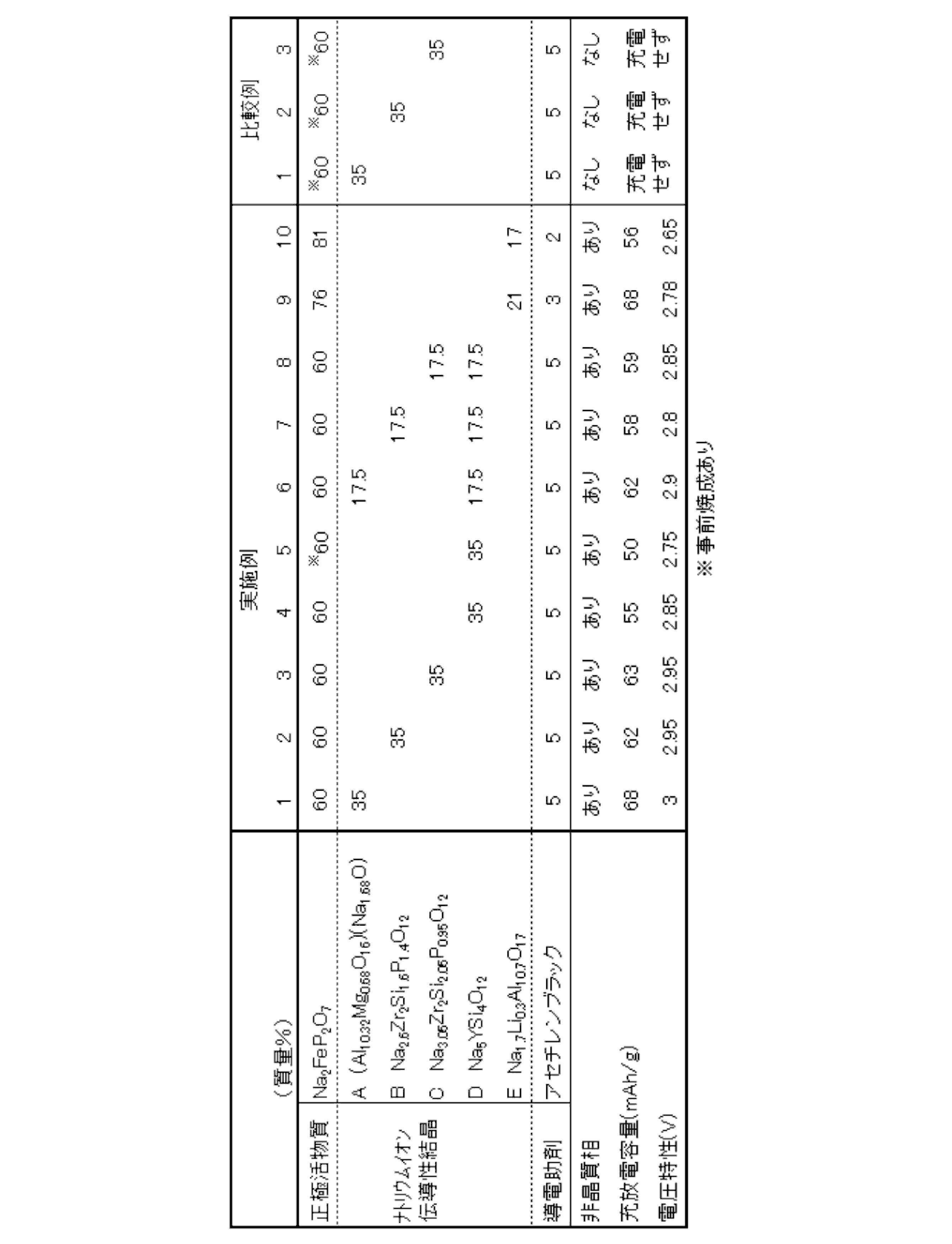
- Example 1 (Production of electrode mixture) It is weighed so that the positive electrode active material crystal precursor powder is 60%, sodium ion conductive crystal A powder is 35%, and acetylene black (SUPAL C65 manufactured by TIMCAL) is 5% by mass, using an agate mortar and pestle. For about 30 minutes. 20 parts by mass of N-methylpyrrolidone containing 10% by mass of polypropylene carbonate (manufactured by Sumitomo Seika Co., Ltd.) was added to 100 parts by mass of the mixed powder, and the mixture was sufficiently stirred using a rotation and revolution mixer to form a slurry. did. All the above operations were performed in an environment with a dew point of ⁇ 40 ° C. or lower.
- the resulting slurry, ⁇ "-Alumina (Ionotec Co., formula: Na 1.7 Li 0.3 Al 10.7 O 17) consisting essentially of sodium ion conductive solid electrolyte layer having a thickness of 0.5mm one
- the surface was coated with an area of 1 cm 2 and a thickness of 200 ⁇ m and dried for 3 hours at 70 ° C.
- the electrode mixture (positive electrode mixture) was formed on one surface of the sodium ion conductive solid electrolyte layer by firing for 1 hour, and the X-ray diffraction pattern of the obtained positive electrode mixture was confirmed.
- Triclinic crystal (Na 2 FeP 2 O 7 ) belonging to space group P-1 which is a crystal and trigonal crystal ( ⁇ ′′ -Allumina [( A diffraction line derived from Al 10.32 Mg 0.68 O 16 ) (Na 1.68 O)]) was confirmed. Further, as a result of observing the obtained electrode mixture with a transmission electron microscope (TEM), a lattice image corresponding to the crystal structure was not seen in a part of the region, and the presence of an amorphous phase was confirmed.
- TEM transmission electron microscope
- a current collector made of a gold electrode having a thickness of 300 nm was formed on the surface of the positive electrode mixture using a sputtering apparatus (SC-701AT, manufactured by Sanyu Electronics Co., Ltd.). After that, in an argon atmosphere with a dew point of ⁇ 60 ° C. or lower, metal sodium as a counter electrode is pressure-bonded to the other surface of the sodium ion conductive solid electrolyte layer, placed on the lower lid of the coin cell, and then covered with the upper lid.
- SC-701AT sputtering apparatus
- charging (releasing sodium ions from the positive electrode active material) is performed by CC (constant current) charging from open circuit voltage (OCV) to 4 V, and discharging (sodium ion occlusion in the positive electrode active material).
- OCV open circuit voltage
- discharging sodium ion occlusion in the positive electrode active material.
- the C rate was 0.02C.
- the charge / discharge capacity was the amount of electricity discharged per unit weight of the positive electrode active material contained in the positive electrode mixture.
- Example 2 In the production of the electrode mixture, an electrode mixture (positive electrode mixture) was formed in the same manner as in Example 1 except that sodium ion conductive crystal B powder was used instead of sodium ion conductive crystal A powder.
- sodium ion conductive crystal B powder was used instead of sodium ion conductive crystal A powder.
- the test battery was produced in the same manner as in Example 1. Using the obtained test battery, a charge / discharge test was conducted in the same manner as in Example 1, and the charge / discharge capacity and the average discharge voltage were measured. The results are shown in Table 1.
- Example 3 In the production of the electrode mixture, an electrode mixture (positive electrode mixture) was formed in the same manner as in Example 1 except that sodium ion conductive crystal C powder was used instead of sodium ion conductive crystal A powder.
- sodium ion conductive crystal C powder was used instead of sodium ion conductive crystal A powder.
- the test battery was produced in the same manner as in Example 1. Using the obtained test battery, a charge / discharge test was conducted in the same manner as in Example 1, and the charge / discharge capacity and the average discharge voltage were measured. The results are shown in Table 1.
- Example 4 In the preparation of the electrode mixture, the same method as in Example 1 was used except that sodium ion conductive crystal D precursor powder was used instead of sodium ion conductive crystal A powder and the firing conditions were 700 ° C. in a nitrogen atmosphere. An electrode mixture (positive electrode mixture) was formed. When the X-ray diffraction pattern of the obtained positive electrode mixture was confirmed, it was found that triclinic crystals (Na 2 FeP 2 O 7 ) belonging to the space group P-1 which are active material crystals and spaces which are sodium ion conductive crystals. A diffraction line derived from a trigonal crystal (Na 5 YSi 4 O 12 ) belonging to group R-3c was confirmed. Moreover, as a result of observing the obtained electrode mixture with TEM, a lattice image corresponding to the crystal structure was not seen in a part of the region, and the presence of an amorphous phase was confirmed.
- sodium ion conductive crystal D precursor powder was used instead of sodium ion conductive crystal
- the test battery was produced in the same manner as in Example 1. Using the obtained test battery, a charge / discharge test was conducted in the same manner as in Example 1, and the charge / discharge capacity and the average discharge voltage were measured. The results are shown in Table 1.
- Example 5 In preparation of the electrode mixture, the positive electrode active material crystal precursor powder was heat-treated at 450 ° C. for one hour in a mixed gas atmosphere of nitrogen and hydrogen (nitrogen 96 volume%, hydrogen 4 volume%) before mixing. Except for the above, an electrode mixture (positive electrode mixture) was formed in the same manner as in Example 4.
- triclinic crystals Na 2 FeP 2 O 7
- space group P-1 which are active material crystals and spaces which are sodium ion conductive crystals.
- a diffraction line derived from a trigonal crystal (Na 5 YSi 4 O 12 ) belonging to group R-3c was confirmed.
- a lattice image corresponding to the crystal structure was not seen in a part of the region, and the presence of an amorphous phase was confirmed.
- the test battery was produced in the same manner as in Example 1. Using the obtained test battery, a charge / discharge test was conducted in the same manner as in Example 1, and the charge / discharge capacity and the average discharge voltage were measured. The results are shown in Table 1.
- Example 6 In the preparation of the electrode mixture, the positive electrode active material crystal precursor powder 60%, the sodium ion conductive crystal A powder 17.5%, the sodium ion conductive crystal D precursor powder 17.5%, and acetylene black 5% by mass.
- the electrode mixture (positive electrode mixture) was formed in the same manner as in Example 1 except that the weight was adjusted to be%.
- the X-ray diffraction pattern of the obtained positive electrode mixture was confirmed, it was found that triclinic crystals (Na 2 FeP 2 O 7 ) belonging to the space group P-1 that are active material crystals, and spaces that are sodium ion conductive crystals.
- Trigonal crystals belonging to group R-3m ( ⁇ ′′ -Allumina [(Al 10.32 Mg 0.68 O 16 ) (Na 1.68 O)]) and space group R-3c which are sodium ion conductive crystals trigonal crystal (Na 5 YSi 4 O 12) diffraction line derived was confirmed that belongs to.
- R-3m ⁇ ′′ -Allumina [(Al 10.32 Mg 0.68 O 16 ) (Na 1.68 O)]
- space group R-3c which are sodium ion conductive crystals trigonal crystal (Na 5 YSi 4 O 12) diffraction line derived was confirmed that belongs to.
- the test battery was produced in the same manner as in Example 1. Using the obtained test battery, a charge / discharge test was conducted in the same manner as in Example 1, and the charge / discharge capacity and the average discharge voltage were measured. The results are shown in Table 1.
- Example 7 In the preparation of the electrode mixture, an electrode mixture (positive electrode mixture) was formed in the same manner as in Example 6 except that sodium ion conductive crystal B powder was used instead of sodium ion conductive crystal A powder. When the X-ray diffraction pattern of the obtained positive electrode mixture was confirmed, it was found that triclinic crystals (Na 2 FeP 2 O 7 ) belonging to the space group P-1 that are active material crystals, and spaces that are sodium ion conductive crystals.
- Trigonal crystals belonging to the group R-3c (Na 2.6 Zr 2 Si 1.6 P 1.4 O 12 ) and trigonal crystals belonging to the space group R-3c which are sodium ion conductive crystals (Na 5 A diffraction line derived from YSi 4 O 12 ) was confirmed. Moreover, as a result of observing the obtained electrode mixture with TEM, a lattice image corresponding to the crystal structure was not seen in a part of the region, and the presence of an amorphous phase was confirmed.
- the test battery was produced in the same manner as in Example 1. Using the obtained test battery, a charge / discharge test was conducted in the same manner as in Example 1, and the charge / discharge capacity and the average discharge voltage were measured. The results are shown in Table 1.
- Example 8 In the preparation of the electrode mixture, an electrode mixture (positive electrode mixture) was formed in the same manner as in Example 6 except that sodium ion conductive crystal C powder was used instead of sodium ion conductive crystal A powder. When the X-ray diffraction pattern of the obtained positive electrode mixture was confirmed, it was found that triclinic crystals (Na 2 FeP 2 O 7 ) belonging to the space group P-1 that are active material crystals, and spaces that are sodium ion conductive crystals.
- the test battery was produced in the same manner as in Example 1. Using the obtained test battery, a charge / discharge test was conducted in the same manner as in Example 1, and the charge / discharge capacity and the average discharge voltage were measured. The results are shown in Table 1.
- Example 9 (Production of electrode mixture) Weighed so that the positive electrode active material crystal precursor powder was 76%, the sodium ion conductive crystal E powder was 21%, and acetylene black (SUPAL C65 manufactured by TIMCAL) was 3% by mass, and using an agate mortar and pestle. For about 30 minutes. 20 parts by mass of N-methylpyrrolidone containing 10% by mass of polypropylene carbonate (manufactured by Sumitomo Seika Co., Ltd.) was added to 100 parts by mass of the mixed powder, and the mixture was sufficiently stirred using a rotation and revolution mixer to form a slurry. did. All the above operations were performed in an environment with a dew point of ⁇ 40 ° C. or lower.
- the obtained slurry was mixed with one of 0.5 mm-thick sodium ion conductive solid electrolyte layers made of MgO-stabilized ⁇ ′′ alumina ((Al 10.32 Mg 0.68 O 16 ) (Na 1.68 O)).
- the surface was coated with an area of 1 cm 2 and a thickness of 80 ⁇ m and dried for 3 hours at 70 ° C.
- the electrode mixture (positive electrode mixture) was formed on one surface of the sodium ion conductive solid electrolyte layer by firing for 1 hour, and the X-ray diffraction pattern of the obtained positive electrode mixture was confirmed.
- Triclinic crystal belonging to space group P-1 which is a crystal and Li 2 O stabilized ⁇ ”alumina (Na 1.7 Li 0.3 Al 10 ) which is a sodium ion conductive crystal .7 O 1 ) Diffraction lines derived from has been confirmed. Further, as a result of observing the obtained electrode mixture with a transmission electron microscope (TEM), a lattice image corresponding to the crystal structure was not seen in a part of the region, and the presence of an amorphous phase was confirmed.
- TEM transmission electron microscope
- a current collector made of a gold electrode having a thickness of 300 nm was formed on the surface of the positive electrode mixture using a sputtering apparatus (SC-701AT, manufactured by Sanyu Electronics Co., Ltd.). After that, in an argon atmosphere with a dew point of ⁇ 60 ° C. or lower, metal sodium as a counter electrode is pressure-bonded to the other surface of the sodium ion conductive solid electrolyte layer, placed on the lower lid of the coin cell, and then covered with the upper lid.
- SC-701AT sputtering apparatus
- charging (releasing sodium ions from the positive electrode active material) is performed by CC (constant current) charging from open circuit voltage (OCV) to 4.3 V, and discharging (sodium ions to the positive electrode active material). (Occlusion) was performed by CC discharge from 4V to 2V. The C rate was 0.01C.
- the charge / discharge capacity was the amount of electricity discharged per unit weight of the positive electrode active material contained in the positive electrode mixture.
- Example 10 The electrode mixture and test battery were the same as in Example 9, except that the composition of the electrode mixture was positive electrode active material crystal precursor powder 81%, sodium ion conductive crystal E powder 17%, acetylene black 3%. Was made. Using the obtained test battery, a charge / discharge test was conducted in the same manner as in Example 9, and the charge / discharge capacity and the average discharge voltage were measured. The results are shown in Table 1.
- the positive electrode active material crystal precursor powder was preliminarily mixed at 450 ° C. in a mixed gas atmosphere of nitrogen and hydrogen (96% by volume of nitrogen and 4% by volume of hydrogen) before mixing with the sodium ion conductive crystal A powder.
- An electrode mixture (positive electrode mixture) was formed in the same manner as in Example 1 except that heat treatment was performed for 1 hour.
- heat treatment was performed for 1 hour.
- a diffraction line derived from a trigonal crystal belonging to the group R-3m ( ⁇ ′′ -Allumina [(Al 10.32 Mg 0.68 O 16 ) (Na 1.68 O)]) was confirmed.
- ⁇ ′′ -Allumina (Al 10.32 Mg 0.68 O 16 ) (Na 1.68 O)]
- the test battery was produced in the same manner as in Example 1. Using the obtained test battery, a charge / discharge test was conducted in the same manner as in Example 1, and the charge / discharge capacity and the average discharge voltage were measured. The results are shown in Table 1.
- Comparative Example 2 In the production of the electrode mixture, an electrode mixture (positive electrode mixture) was formed in the same manner as in Comparative Example 1, except that sodium ion conductive crystal B powder was used instead of sodium ion conductive crystal A powder.
- triclinic crystals Na 2 FeP 2 O 7
- space group P-1 which are active material crystals and spaces which are sodium ion conductive crystals.
- a diffraction line derived from a trigonal crystal (Na 2.6 Zr 2 Si 1.6 P 1.4 O 12 ) belonging to the group R-3c was confirmed. Further, as a result of observing the obtained electrode mixture with TEM, a lattice image corresponding to the crystal structure was observed in the entire region, and an amorphous phase was not confirmed.
- the test battery was produced in the same manner as in Example 1. Using the obtained test battery, a charge / discharge test was conducted in the same manner as in Example 1, and the charge / discharge capacity and the average discharge voltage were measured. The results are shown in Table 1.
- the test battery was produced in the same manner as in Example 1. Using the obtained test battery, a charge / discharge test was conducted in the same manner as in Example 1, and the charge / discharge capacity and the average discharge voltage were measured. The results are shown in Table 1.
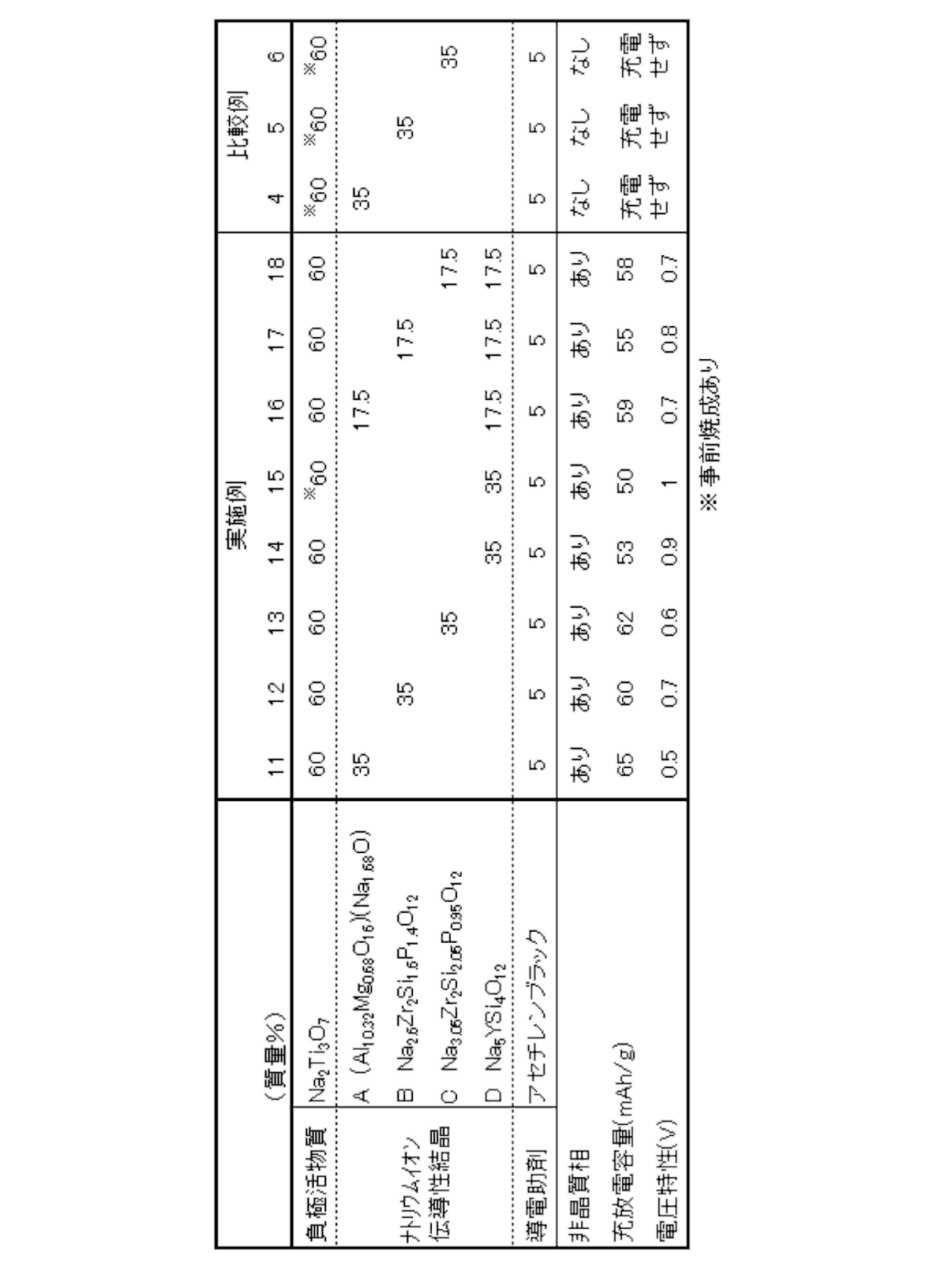
- Example 11 In the preparation of the electrode mixture, a negative electrode active material crystal precursor powder was used instead of the positive electrode active material crystal precursor powder, and the same method as in Example 1 was applied to one surface of the sodium ion conductive solid electrolyte layer. An electrode mixture (negative electrode mixture) was formed. When the X-ray diffraction pattern of the obtained negative electrode mixture was confirmed, it was a monoclinic crystal (Na 2 Ti 3 O 7 ) and a sodium ion conductive crystal belonging to the space group P2 1 / m as active material crystals.
- a diffraction line derived from a trigonal crystal ( ⁇ ′′ -Allumina [(Al 10.32 Mg 0.68 O 16 ) (Na 1.68 O)]) belonging to the space group R-3m was confirmed.
- ⁇ ′′ -Allumina [(Al 10.32 Mg 0.68 O 16 ) (Na 1.68 O)] a lattice image corresponding to the crystal structure was not seen in some regions, and the presence of an amorphous phase was confirmed.
- a current collector made of a gold electrode having a thickness of 300 nm was formed on the surface of the negative electrode mixture using a sputtering apparatus. Thereafter, in an argon atmosphere with a dew point of ⁇ 60 ° C. or lower, metallic sodium as a counter electrode is pressure-bonded to the other surface of the sodium ion conductive solid electrolyte layer, placed on the lower lid of the coin cell, and then covered with the upper lid. A CR2032-type test battery was produced.
- charging sodium ion occlusion in the negative electrode active material
- CC constant current charging from open circuit voltage (OCV) to 0 V
- discharging sodium ion release from the negative electrode active material
- OCV open circuit voltage
- the C rate was 0.02C.
- the charge / discharge capacity was the amount of electricity discharged per unit weight of the negative electrode active material contained in the negative electrode mixture.
- Example 12 In the production of the electrode mixture, an electrode mixture (negative electrode mixture) was formed in the same manner as in Example 11 except that sodium ion conductive crystal B powder was used instead of sodium ion conductive crystal A powder.
- the X-ray diffraction pattern of the obtained negative electrode mixture was confirmed, it was a monoclinic crystal (Na 2 Ti 3 O 7 ) and a sodium ion conductive crystal belonging to the space group P2 1 / m as active material crystals.
- a diffraction line derived from a trigonal crystal (Na 2.6 Zr 2 Si 1.6 P 1.4 O 12 ) belonging to the space group R-3c was confirmed.
- a lattice image corresponding to the crystal structure was not seen in a part of the region, and the presence of an amorphous phase was confirmed.
- the test battery was produced in the same manner as in Example 11. Using the obtained test battery, a charge / discharge test was conducted in the same manner as in Example 11, and the charge / discharge capacity and the average discharge voltage were measured. The results are shown in Table 2.
- Example 13 In the preparation of the electrode mixture, an electrode mixture (negative electrode mixture) was formed in the same manner as in Example 11 except that sodium ion conductive crystal C powder was used instead of sodium ion conductive crystal A powder.
- the X-ray diffraction pattern of the obtained negative electrode mixture was confirmed, it was a monoclinic crystal (Na 2 Ti 3 O 7 ) and a sodium ion conductive crystal belonging to the space group P2 1 / m as active material crystals.
- a diffraction line derived from a trigonal crystal (Na 3.05 Zr 2 Si 2.05 P 0.95 O 12 ) belonging to the space group R-3c was confirmed.
- a lattice image corresponding to the crystal structure was not seen in a part of the region, and the presence of an amorphous phase was confirmed.
- the test battery was produced in the same manner as in Example 11. Using the obtained test battery, a charge / discharge test was conducted in the same manner as in Example 11, and the charge / discharge capacity and the average discharge voltage were measured. The results are shown in Table 2.
- Example 14 In the preparation of the electrode mixture, an electrode mixture (negative electrode mixture) was formed in the same manner as in Example 11 except that sodium ion conductive crystal D precursor powder was used instead of sodium ion conductive crystal A powder. did.
- the X-ray diffraction pattern of the obtained negative electrode mixture was confirmed, it was a monoclinic crystal (Na 2 Ti 3 O 7 ) and a sodium ion conductive crystal belonging to the space group P2 1 / m as active material crystals.
- space group R-3c belonging trigonal crystal (Na 5 YSi 4 O 12) diffraction line derived was confirmed.
- a lattice image corresponding to the crystal structure was not seen in a part of the region, and the presence of an amorphous phase was confirmed.
- the test battery was produced in the same manner as in Example 11. Using the obtained test battery, a charge / discharge test was conducted in the same manner as in Example 11, and the charge / discharge capacity and the average discharge voltage were measured. The results are shown in Table 2.
- Example 15 In the preparation of the electrode mixture, the electrode mixture (negative electrode) was prepared in the same manner as in Example 14 except that the negative electrode active material crystal precursor powder was heat-treated at 800 ° C. for 1 hour in the air before mixing. Compound) was formed. When the X-ray diffraction pattern of the obtained negative electrode mixture was confirmed, it was a monoclinic crystal (Na 2 Ti 3 O 7 ) and a sodium ion conductive crystal belonging to the space group P2 1 / m as active material crystals. space group R-3c belonging trigonal crystal (Na 5 YSi 4 O 12) diffraction line derived was confirmed. Moreover, as a result of observing the obtained electrode mixture with TEM, a lattice image corresponding to the crystal structure was not seen in a part of the region, and the presence of an amorphous phase was confirmed.
- the test battery was produced in the same manner as in Example 11. Using the obtained test battery, a charge / discharge test was conducted in the same manner as in Example 11, and the charge / discharge capacity and the average discharge voltage were measured. The results are shown in Table 2.
- Example 16 In the preparation of the electrode mixture, mass%, negative electrode active material crystal precursor powder 60%, sodium ion conductive solid electrolyte A powder 17.5%, sodium ion conductive crystal D precursor powder 17.5%, acetylene black An electrode mixture (negative electrode mixture) was formed in the same manner as in Example 11 except that it was weighed to 5%. When an X-ray diffraction pattern of the obtained negative electrode mixture was confirmed, it was a monoclinic crystal (Na 2 Ti 3 O 7 ) belonging to the space group P2 1 / m, which is an active material crystal, and a sodium ion conductive crystal.
- Trigonal crystals belonging to the space group R-3m ( ⁇ ′′ -Allumina [(Al 10.32 Mg 0.68 O 16 ) (Na 1.68 O)]) and the space group R—
- the diffraction line derived from the trigonal crystal (Na 5 YSi 4 O 12 ) belonging to 3c was confirmed, and the obtained electrode mixture was observed by TEM, and as a result, a lattice corresponding to the crystal structure in a part of the region was observed. No image was observed, and the presence of an amorphous phase was confirmed.
- the test battery was produced in the same manner as in Example 11. Using the obtained test battery, a charge / discharge test was conducted in the same manner as in Example 11, and the charge / discharge capacity and the average discharge voltage were measured. The results are shown in Table 2.
- Example 17 In the preparation of the electrode mixture, an electrode mixture (negative electrode mixture) was formed in the same manner as in Example 16 except that sodium ion conductive crystal B powder was used instead of sodium ion conductive crystal A powder. When an X-ray diffraction pattern of the obtained negative electrode mixture was confirmed, it was a monoclinic crystal (Na 2 Ti 3 O 7 ) belonging to the space group P2 1 / m, which is an active material crystal, and a sodium ion conductive crystal.
- the test battery was produced in the same manner as in Example 11. Using the obtained test battery, a charge / discharge test was conducted in the same manner as in Example 11, and the charge / discharge capacity and the average discharge voltage were measured. The results are shown in Table 2.
- Example 18 In the production of the electrode mixture, an electrode mixture (negative electrode mixture) was formed in the same manner as in Example 16 except that sodium ion conductive crystal C powder was used instead of sodium ion conductive crystal A powder. When an X-ray diffraction pattern of the obtained negative electrode mixture was confirmed, it was a monoclinic crystal (Na 2 Ti 3 O 7 ) belonging to the space group P2 1 / m, which is an active material crystal, and a sodium ion conductive crystal.
- the test battery was produced in the same manner as in Example 11. Using the obtained test battery, a charge / discharge test was conducted in the same manner as in Example 11, and the charge / discharge capacity and the average discharge voltage were measured. The results are shown in Table 2.
- Example 11 In the preparation of the electrode mixture, Example 11 was performed except that the negative electrode active material crystal precursor powder was heat-treated at 800 ° C. for 1 hour in a nitrogen atmosphere before mixing with the sodium ion conductive crystal A powder. An electrode mixture (negative electrode mixture) was formed in the same manner. When the X-ray diffraction pattern of the obtained negative electrode mixture was confirmed, it was a monoclinic crystal (Na 2 Ti 3 O 7 ) and a sodium ion conductive crystal belonging to the space group P2 1 / m as active material crystals. space group R-3m belonging trigonal crystals ( ⁇ "-Alumina [(Al 10.32 Mg 0.68 O 16) (Na 1.68 O)]) diffraction line derived was confirmed. in addition, to obtain As a result of observing the obtained electrode mixture with TEM, a lattice image corresponding to the crystal structure was observed in all regions, and an amorphous phase was not confirmed.
- the test battery was produced in the same manner as in Example 11. Using the obtained test battery, a charge / discharge test was conducted in the same manner as in Example 11, and the charge / discharge capacity and the average discharge voltage were measured. The results are shown in Table 2.
- an electrode mixture (negative electrode mixture) was formed in the same manner as in Comparative Example 3 except that sodium ion conductive crystal B powder was used instead of sodium ion conductive crystal A powder.
- the X-ray diffraction pattern of the obtained negative electrode mixture was confirmed, it was a monoclinic crystal (Na 2 Ti 3 O 7 ) and a sodium ion conductive crystal belonging to the space group P2 1 / m as active material crystals.
- a diffraction line derived from a trigonal crystal (Na 2.6 Zr 2 Si 1.6 P 1.4 O 12 ) belonging to the space group R-3c was confirmed. Further, as a result of observing the obtained electrode mixture with TEM, a lattice image corresponding to the crystal structure was observed in the entire region, and an amorphous phase was not confirmed.
- the test battery was produced in the same manner as in Example 11. Using the obtained test battery, a charge / discharge test was conducted in the same manner as in Example 11, and the charge / discharge capacity and the average discharge voltage were measured. The results are shown in Table 2.
- an electrode mixture (negative electrode mixture) was formed in the same manner as in Comparative Example 3 except that sodium ion conductive crystal C powder was used instead of sodium ion conductive crystal A powder.
- the X-ray diffraction pattern of the obtained negative electrode mixture was confirmed, it was a monoclinic crystal (Na 2 Ti 3 O 7 ) and a sodium ion conductive crystal belonging to the space group P2 1 / m as active material crystals.
- a diffraction line derived from a trigonal crystal (Na 3.05 Zr 2 Si 2.05 P 0.95 O 12 ) belonging to the space group R-3c was confirmed. Further, as a result of observing the obtained electrode mixture with TEM, a lattice image corresponding to the crystal structure was observed in the entire region, and an amorphous phase was not confirmed.
- the test battery was produced in the same manner as in Example 11. Using the obtained test battery, a charge / discharge test was conducted in the same manner as in Example 11, and the charge / discharge capacity and the average discharge voltage were measured. The results are shown in Table 2.
- test batteries of Examples 1 to 10 were able to be charged / discharged, had a charge / discharge capacity of 50 to 68 mAh / g, and a discharge voltage of 2.65 to 3.0V. On the other hand, the test batteries of Comparative Examples 1 to 3 could not be charged.
- test batteries of Examples 11 to 18 were able to be charged / discharged, had a charge / discharge capacity of 50 to 65 mAh / g, and a discharge voltage of 0.5 to 1.0V. On the other hand, the test batteries of Comparative Examples 4 to 6 could not be charged.
Landscapes
- Chemical & Material Sciences (AREA)
- Chemical Kinetics & Catalysis (AREA)
- General Chemical & Material Sciences (AREA)
- Electrochemistry (AREA)
- Engineering & Computer Science (AREA)
- Inorganic Chemistry (AREA)
- Manufacturing & Machinery (AREA)
- Materials Engineering (AREA)
- Physics & Mathematics (AREA)
- Condensed Matter Physics & Semiconductors (AREA)
- General Physics & Mathematics (AREA)
- Crystallography & Structural Chemistry (AREA)
- Composite Materials (AREA)
- Organic Chemistry (AREA)
- Life Sciences & Earth Sciences (AREA)
- Geochemistry & Mineralogy (AREA)
- Battery Electrode And Active Subsutance (AREA)
- Secondary Cells (AREA)
- Glass Compositions (AREA)
Abstract
Description
本発明のナトリウムイオン二次電池用電極合材は、活物質結晶、ナトリウムイオン伝導性結晶及び非晶質相を含むことを特徴とする。ナトリウムイオン二次電池用電極合材中に、活物質結晶やナトリウムイオン伝導性結晶に加え、非晶質相が含まれるため、非晶質相が、活物質結晶とナトリウムイオン伝導性結晶との界面に存在しやすくなり、ナトリウムイオン二次電池の充放電時にナトリウムイオンの伝導パスとなる活物質結晶とナトリウムイオン伝導性結晶との間の界面抵抗が低下しやすくなり、ナトリウム二次電池の充放電容量や電池電圧が高くなりやすい。
活物質結晶は、正極活物質又は負極活物質として作用するものであり、充放電の際には、ナトリウムイオンの吸蔵・放出を行うことができる。
ナトリウムイオン伝導性結晶は、活物質結晶と対極との間のナトリウムイオン伝導パスとして作用し、ナトリウムイオンの伝導性に優れ、電子絶縁性の高い結晶である。ナトリウムイオン伝導性結晶がなければ、活物質結晶と対極との間のナトリウムイオンの移動抵抗が非常に高くなり、充放電容量や電池電圧が低下する。ナトリウムイオン伝導性結晶は、Al、Y、Zr、Si及びPから選ばれる少なくとも1種、Na及びOを含む結晶であることが好ましい。上記構成にすることにより、ナトリウムイオンの伝導性に優れ、電子絶縁性が高くでき、さらに安定性に優れる。
非晶質相は、前述のとおり、活物質結晶やナトリウムイオン伝導性結晶の結晶界面でのナトリウムイオン伝導パスとして作用し、電極合材におけるナトリウムイオンの伝導性を向上させる効果がある。
電極合材は、さらに導電助剤を含有することが好ましい。導電助剤は、電極合材の高容量化やハイレート化を達成するために添加される成分である。導電助剤の具体例としては、アセチレンブラックやケッチェンブラック等の高導電性カーボンブラック、黒鉛、コークス等や、Ni粉末、Cu粉末、Ag粉末等の金属粉末などが挙げられる。なかでも、極少量の添加で優れた導電性を発揮する高導電性カーボンブラック、Ni粉末、Cu粉末のいずれかを用いることが好ましい。
本発明のナトリウム全固体電池は、前記ナトリウムイオン二次電池用電極合材を正極又は負極として使用することを特徴とする。図1は、全固体電池の一形態例を示す断面模式図である。図1に示すナトリウム全固体電池1において、正極2とナトリウムイオン伝導性固体電解質層3と負極4とがこの順序に積層されている。正極2は、ナトリウムイオン伝導性固体電解質層3側から順に、正極電極合材5と、正極電極合材5の集電を行う正極集電体6とを備える。負極4は、ナトリウムイオン伝導性固体電解質層3側から順に、負極電極合材7と、負極電極合材7の集電を行う負極集電体8とを備える。ナトリウム全固体電池1は、正極電極合材5又は負極電極合材7が非晶質相を含むため、正極2とナトリウムイオン伝導性固体電解質層3又は負極4とナトリウムイオン伝導性固体電解質層3の界面が非晶質相により接着強度が高くなり、充放電容量や電池電圧が高くなりやすい。
次に、本発明のナトリウムイオン二次電池用電極合材の製造方法について説明する。
メタリン酸ナトリウム(NaPO3)、酸化第二鉄(Fe2O3)、およびオルソリン酸(H3PO4)を原料とし、モル%で、Na2O 40.0%、Fe2O3 20.0%、P2O5 40.0%となるように原料粉末を調合し、1250℃にて45分間、大気雰囲気中にて溶融を行った。その後、一対のロールに溶融ガラスを流し込み、急冷しながらフィルム状に成形することにより、正極活物質結晶前駆体を作製した。
炭酸ナトリウム(Na2CO3)、酸化チタン(TiO2)、および無水ホウ酸(B2O3)を原料とし、モル%で、Na2O 36.0%、TiO2 49.0%、B2O3 15.0%となるように原料粉末を調合し、1300℃にて1時間、大気雰囲気中にて溶融を行った。その後、一対のロールに溶融ガラスを流し込み、急冷しながらフィルム状に成形することにより、負極活物質結晶前駆体を作製した。
炭酸ナトリウム(Na2CO3)、酸化アルミニウム(Al2O3)、および酸化マグネシウム(MgO)を原料とし、モル%で、Na2O 13.0%、Al2O3 80.2%、MgO 6.8%となるように原料粉末を調合し、大気雰囲気中1250℃にて4時間焼成を行った。焼成後の粉末について、φ20mmのAl2O3玉石を使用したボールミル粉砕を24時間行った。その後、空気分級することにより、平均粒子径D50 2.0μmの粉末を得た。得られた粉末を、大気雰囲気中1640℃にて1時間熱処理を行うことにより、ナトリウムイオン伝導性結晶A粉末を得た。得られたナトリウムイオン伝導性結晶A粉末は、速やかに露点-40℃以下の環境に移し、保存した。
メタリン酸ナトリウム(NaPO3)、酸化ジルコニウム(ZrO2)、炭酸ナトリウム(Na2CO3)、および二酸化ケイ素(SiO2)を原料とし、モル%で、Na2O 29.1%、ZrO2 23.6%、P2O5 7.3%、SiO2 40%となるように原料粉末を調合し、大気雰囲気中1150℃にて1時間焼成を行った。焼成後の粉末について、φ20mmのAl2O3玉石を使用したボールミル粉砕を24時間行った。その後、空気分級することにより、平均粒子径D50 2.0μmの粉末を得た。得られた粉末を、大気雰囲気中1300℃にて2時間熱処理を行うことにより、ナトリウムイオン伝導性結晶B粉末を得た。得られたナトリウムイオン伝導性結晶B粉末は、速やかに露点-40℃以下の環境に移し、保存した。
メタリン酸ナトリウム(NaPO3)、イットリア安定ジルコニア((ZrO2)0.97(Y2O3)0.03)、炭酸ナトリウム(Na2CO3)、および二酸化ケイ素(SiO2)を原料とし、モル%で、Na2O 25.3%、ZrO2 31.6%、Y2O3 1.0%、P2O5 8.4%、SiO2 33.7%となるように原料粉末を調合し、大気雰囲気中1100℃にて8時間焼成を行った。焼成後の粉末について、φ20mmのAl2O3玉石を使用したボールミル粉砕を24時間行った。その後、空気分級することにより、平均粒子径D50 2.0μmの粉末を得た。得られた粉末を、大気雰囲気中1250℃にて40時間熱処理を行うことにより、ナトリウムイオン伝導性結晶C粉末を得た。得られたナトリウムイオン伝導性結晶C粉末は、速やかに露点-40℃以下の環境に移し、保存した。
メタリン酸ナトリウム(NaPO3)、酸化イットリウム(Y2O3)、炭酸ナトリウム(Na2CO3)、および二酸化ケイ素(SiO2)を原料とし、モル%で、Na2O 38.2%、Y2O3 5.9%、P2O5 2.9%、SiO2 52.9%となるように原料粉末を調合し、1550℃にて4時間、大気雰囲気中にて溶融を行った。その後、一対のロールに溶融ガラスを流し込み、急冷しながらフィルム状に成形することにより、ナトリウムイオン伝導性結晶D前駆体を作製した。
Ionotec社製、組成式:Na1.7Li0.3Al10.7O17のLi2O安定化β”アルミナを厚み0.5mmのシート状に加工した。シート状のLi2O安定化β”アルミナをメノウ製の乳鉢及び乳棒を用いて粉砕し、目開き20μmの篩に通過させることで、平均粒子径17μmの粉末状固体電解質を得た。
(電極合材の作製)
質量%で、正極活物質結晶前駆体粉末 60%、ナトリウムイオン伝導性結晶A粉末 35%、アセチレンブラック(TIMCAL社製 SUPER C65) 5%となるように秤量し、メノウ製の乳鉢および乳棒を用いて約30分間混合した。混合した粉末100質量部に、10質量%のポリプロピレンカーボネート(住友精化株式会社製)を含有したN-メチルピロリドンを20質量部添加して、自転公転ミキサーを用いて十分に撹拌し、スラリー化した。なお、上記の操作はすべて露点-40℃以下の環境で行った。
次に、正極合材の表面にスパッタ装置(サンユー電子株式会社製 SC-701AT)を用いて厚さ300nmの金電極からなる集電体を形成した。その後、露点-60℃以下のアルゴン雰囲気中にて、対極となる金属ナトリウムを前記ナトリウムイオン伝導性固体電解質層の他方の表面に圧着し、コインセルの下蓋に載置した後、上蓋を被せてCR2032型試験電池を作製した。
得られた試験電池を用いて70℃で充放電試験を行い、充放電容量および平均放電電圧を測定した。結果を表1に示す。
電極合材の作製において、ナトリウムイオン伝導性結晶A粉末の代わりにナトリウムイオン伝導性結晶B粉末を用いた以外は、実施例1と同様の方法で電極合材(正極合材)を形成した。得られた正極合材についてX線回折パターンを確認したところ、活物質結晶である空間群P-1に属する三斜晶系結晶(Na2FeP2O7)およびナトリウムイオン伝導性結晶である空間群R-3cに属する三方晶系結晶(Na2.6Zr2Si1.6P1.4O12)由来の回折線が確認された。また、得られた電極合材をTEMにより観察した結果、一部の領域において結晶構造に相当する格子像は見られず、非晶質相の存在が確認された。
電極合材の作製において、ナトリウムイオン伝導性結晶A粉末の代わりにナトリウムイオン伝導性結晶C粉末を用いた以外は、実施例1と同様の方法で電極合材(正極合材)を形成した。得られた正極合材についてX線回折パターンを確認したところ、活物質結晶である空間群P-1に属する三斜晶系結晶(Na2FeP2O7)およびナトリウムイオン伝導性結晶である空間群R-3cに属する三方晶系結晶(Na3.05Zr2Si2.05P0.95O12)由来の回折線が確認された。また、得られた電極合材をTEMにより観察した結果、一部の領域において結晶構造に相当する格子像は見られず、非晶質相の存在が確認された。
電極合材の作製において、ナトリウムイオン伝導性結晶A粉末の代わりにナトリウムイオン伝導性結晶D前駆体粉末を用い、焼成条件を窒素雰囲気中700℃とした以外は、実施例1と同様の方法で電極合材(正極合材)を形成した。得られた正極合材についてX線回折パターンを確認したところ、活物質結晶である空間群P-1に属する三斜晶系結晶(Na2FeP2O7)およびナトリウムイオン伝導性結晶である空間群R-3cに属する三方晶系結晶(Na5YSi4O12)由来の回折線が確認された。また、得られた電極合材をTEMにより観察した結果、一部の領域において結晶構造に相当する格子像は見られず、非晶質相の存在が確認された。
電極合材の作製において、正極活物質結晶前駆体粉末を、混合前にあらかじめ窒素と水素の混合ガス雰囲気(窒素96体積%、水素4体積%)中450℃にて1時間熱処理を行ったこと以外は、実施例4と同様の方法で電極合材(正極合材)を形成した。得られた正極合材についてX線回折パターンを確認したところ、活物質結晶である空間群P-1に属する三斜晶系結晶(Na2FeP2O7)およびナトリウムイオン伝導性結晶である空間群R-3cに属する三方晶系結晶(Na5YSi4O12)由来の回折線が確認された。また、得られた電極合材をTEMにより観察した結果、一部の領域において結晶構造に相当する格子像は見られず、非晶質相の存在が確認された。
電極合材の作製において、質量%で、正極活物質結晶前駆体粉末 60%、ナトリウムイオン伝導性結晶A粉末 17.5%、ナトリウムイオン伝導性結晶D前駆体粉末 17.5%、アセチレンブラック 5%となるように秤量したこと以外は、実施例1と同様の方法で電極合材(正極合材)を形成した。得られた正極合材についてX線回折パターンを確認したところ、活物質結晶である空間群P-1に属する三斜晶系結晶(Na2FeP2O7)、ナトリウムイオン伝導性結晶である空間群R-3mに属する三方晶系結晶(β”-Alumina [(Al10.32Mg0.68O16)(Na1.68O)])およびナトリウムイオン伝導性結晶である空間群R-3cに属する三方晶系結晶(Na5YSi4O12)由来の回折線が確認された。また、得られた電極合材をTEMにより観察した結果、一部の領域において結晶構造に相当する格子像は見られず、非晶質相の存在が確認された。
電極合材の作製において、ナトリウムイオン伝導性結晶A粉末の代わりにナトリウムイオン伝導性結晶B粉末を用いた以外は、実施例6と同様の方法で電極合材(正極合材)を形成した。得られた正極合材についてX線回折パターンを確認したところ、活物質結晶である空間群P-1に属する三斜晶系結晶(Na2FeP2O7)、ナトリウムイオン伝導性結晶である空間群R-3cに属する三方晶系結晶(Na2.6Zr2Si1.6P1.4O12)およびナトリウムイオン伝導性結晶である空間群R-3cに属する三方晶系結晶(Na5YSi4O12)由来の回折線が確認された。また、得られた電極合材をTEMにより観察した結果、一部の領域において結晶構造に相当する格子像は見られず、非晶質相の存在が確認された。
電極合材の作製において、ナトリウムイオン伝導性結晶A粉末の代わりにナトリウムイオン伝導性結晶C粉末を用いた以外は、実施例6と同様の方法で電極合材(正極合材)を形成した。得られた正極合材についてX線回折パターンを確認したところ、活物質結晶である空間群P-1に属する三斜晶系結晶(Na2FeP2O7)、ナトリウムイオン伝導性結晶である空間群R-3cに属する三方晶系結晶(Na3.05Zr2Si2.05P0.95O12)およびナトリウムイオン伝導性結晶である空間群R-3cに属する三方晶系結晶(Na5YSi4O12)由来の回折線が確認された。また、得られた電極合材をTEMにより観察した結果、一部の領域において結晶構造に相当する格子像は見られず、非晶質相の存在が確認された。
(電極合材の作製)
質量%で、正極活物質結晶前駆体粉末 76%、ナトリウムイオン伝導性結晶E粉末 21%、アセチレンブラック(TIMCAL社製 SUPER C65) 3%となるように秤量し、メノウ製の乳鉢および乳棒を用いて約30分間混合した。混合した粉末100質量部に、10質量%のポリプロピレンカーボネート(住友精化株式会社製)を含有したN-メチルピロリドンを20質量部添加して、自転公転ミキサーを用いて十分に撹拌し、スラリー化した。なお、上記の操作はすべて露点-40℃以下の環境で行った。
次に、正極合材の表面にスパッタ装置(サンユー電子株式会社製 SC-701AT)を用いて厚さ300nmの金電極からなる集電体を形成した。その後、露点-60℃以下のアルゴン雰囲気中にて、対極となる金属ナトリウムを前記ナトリウムイオン伝導性固体電解質層の他方の表面に圧着し、コインセルの下蓋に載置した後、上蓋を被せてCR2032型試験電池を作製した。
得られた試験電池を用いて60℃で充放電試験を行い、充放電容量および平均放電電圧を測定した。結果を表1に示す。
電極合材の組成を、正極活物質結晶前駆体粉末 81%、ナトリウムイオン伝導性結晶E粉末 17%、アセチレンブラック 3%としたこと以外は、実施例9と同様にして電極合材及び試験電池を作製した。得られた試験電池を用いて実施例9と同様の方法で充放電試験を行い、充放電容量および平均放電電圧を測定した。結果を表1に示す。
電極合材の作製において、正極活物質結晶前駆体粉末を、ナトリウムイオン伝導性結晶A粉末との混合前にあらかじめ窒素と水素の混合ガス雰囲気(窒素96体積%、水素4体積%)中450℃にて1時間熱処理を行ったこと以外は、実施例1と同様の方法で電極合材(正極合材)を形成した。得られた正極合材についてX線回折パターンを確認したところ、活物質結晶である空間群P-1に属する三斜晶系結晶(Na2FeP2O7)およびナトリウムイオン伝導性結晶である空間群R-3mに属する三方晶系結晶(β”-Alumina [(Al10.32Mg0.68O16)(Na1.68O)])由来の回折線が確認された。また、得られた電極合材をTEMにより観察した結果、全領域において結晶構造に相当する格子像が観察され、非晶質相は確認されなかった。
電極合材の作製において、ナトリウムイオン伝導性結晶A粉末の代わりにナトリウムイオン伝導性結晶B粉末を用いた以外は、比較例1と同様の方法で電極合材(正極合材)を形成した。得られた正極合材についてX線回折パターンを確認したところ、活物質結晶である空間群P-1に属する三斜晶系結晶(Na2FeP2O7)およびナトリウムイオン伝導性結晶である空間群R-3cに属する三方晶系結晶(Na2.6Zr2Si1.6P1.4O12)由来の回折線が確認された。また、得られた電極合材をTEMにより観察した結果、全領域において結晶構造に相当する格子像が観察され、非晶質相は確認されなかった。
電極合材の作製において、ナトリウムイオン伝導性結晶A粉末の代わりにナトリウムイオン伝導性結晶C粉末を用いた以外は、比較例1と同様の方法で電極合材(正極合材)を形成した。得られた正極合材についてX線回折パターンを確認したところ、活物質結晶である空間群P-1に属する三斜晶系結晶(Na2FeP2O7)およびナトリウムイオン伝導性結晶である空間群R-3cに属する三方晶系結晶(Na3.05Zr2Si2.05P0.95O12)由来の回折線が確認された。また、得られた電極合材をTEMにより観察した結果、全領域において結晶構造に相当する格子像が観察され、非晶質相は確認されなかった。
電極合材の作製において、正極活物質結晶前駆体粉末の代わりに負極活物質結晶前駆体粉末を用いた以外は、実施例1と同様の方法でナトリウムイオン伝導性固体電解質層の一方の表面に電極合材(負極合材)を形成した。得られた負極合材についてX線回折パターンを確認したところ、活物質結晶である空間群P21/mに属する単斜晶系結晶(Na2Ti3O7)およびナトリウムイオン伝導性結晶である空間群R-3mに属する三方晶系結晶(β”-Alumina [(Al10.32Mg0.68O16)(Na1.68O)])由来の回折線が確認された。また、得られた電極合材をTEMにより観察した結果、一部の領域において結晶構造に相当する格子像は見られず、非晶質相の存在が確認された。
電極合材の作製において、ナトリウムイオン伝導性結晶A粉末の代わりにナトリウムイオン伝導性結晶B粉末を用いた以外は、実施例11と同様の方法で電極合材(負極合材)を形成した。得られた負極合材についてX線回折パターンを確認したところ、活物質結晶である空間群P21/mに属する単斜晶系結晶(Na2Ti3O7)およびナトリウムイオン伝導性結晶である空間群R-3cに属する三方晶系結晶(Na2.6Zr2Si1.6P1.4O12)由来の回折線が確認された。また、得られた電極合材をTEMにより観察した結果、一部の領域において結晶構造に相当する格子像は見られず、非晶質相の存在が確認された。
電極合材の作製において、ナトリウムイオン伝導性結晶A粉末の代わりにナトリウムイオン伝導性結晶C粉末を用いた以外は、実施例11と同様の方法で電極合材(負極合材)を形成した。得られた負極合材についてX線回折パターンを確認したところ、活物質結晶である空間群P21/mに属する単斜晶系結晶(Na2Ti3O7)およびナトリウムイオン伝導性結晶である空間群R-3cに属する三方晶系結晶(Na3.05Zr2Si2.05P0.95O12)由来の回折線が確認された。また、得られた電極合材をTEMにより観察した結果、一部の領域において結晶構造に相当する格子像は見られず、非晶質相の存在が確認された。
電極合材の作製において、ナトリウムイオン伝導性結晶A粉末の代わりにナトリウムイオン伝導性結晶D前駆体粉末を用いた以外は、実施例11と同様の方法で電極合材(負極合材)を形成した。得られた負極合材についてX線回折パターンを確認したところ、活物質結晶である空間群P21/mに属する単斜晶系結晶(Na2Ti3O7)およびナトリウムイオン伝導性結晶である空間群R-3cに属する三方晶系結晶(Na5YSi4O12)由来の回折線が確認された。また、得られた電極合材をTEMにより観察した結果、一部の領域において結晶構造に相当する格子像は見られず、非晶質相の存在が確認された。
電極合材の作製において、負極活物質結晶前駆体粉末を、混合前にあらかじめ大気雰囲気中800℃にて1時間熱処理を行ったこと以外は、実施例14と同様の方法で電極合材(負極合材)を形成した。得られた負極合材についてX線回折パターンを確認したところ、活物質結晶である空間群P21/mに属する単斜晶系結晶(Na2Ti3O7)およびナトリウムイオン伝導性結晶である空間群R-3cに属する三方晶系結晶(Na5YSi4O12)由来の回折線が確認された。また、得られた電極合材をTEMにより観察した結果、一部の領域において結晶構造に相当する格子像は見られず、非晶質相の存在が確認された。
電極合材の作製において、質量%で、負極活物質結晶前駆体粉末 60%、ナトリウムイオン伝導性固体電解質A粉末 17.5%、ナトリウムイオン伝導性結晶D前駆体粉末 17.5%、アセチレンブラック 5%となるように秤量したこと以外は、実施例11と同様の方法で電極合材(負極合材)を形成した。得られた負極合材についてX線回折パターンを確認したところ、活物質結晶である空間群P21/mに属する単斜晶系結晶(Na2Ti3O7)、ナトリウムイオン伝導性結晶である空間群R-3mに属する三方晶系結晶(β”-Alumina [(Al10.32Mg0.68O16)(Na1.68O)])およびナトリウムイオン伝導性結晶である空間群R-3cに属する三方晶系結晶(Na5YSi4O12)由来の回折線が確認された。また、得られた電極合材をTEMにより観察した結果、一部の領域において結晶構造に相当する格子像は見られず、非晶質相の存在が確認された。
電極合材の作製において、ナトリウムイオン伝導性結晶A粉末の代わりにナトリウムイオン伝導性結晶B粉末を用いた以外は、実施例16と同様の方法で電極合材(負極合材)を形成した。得られた負極合材についてX線回折パターンを確認したところ、活物質結晶である空間群P21/mに属する単斜晶系結晶(Na2Ti3O7)、ナトリウムイオン伝導性結晶である空間群R-3cに属する三方晶系結晶(Na2.6Zr2Si1.6P1.4O12)およびナトリウムイオン伝導性結晶である三方晶系結晶(Na5YSi4O12)由来の回折線が確認された。また、得られた電極合材をTEMにより観察した結果、一部の領域において結晶構造に相当する格子像は見られず、非晶質相の存在が確認された。
電極合材の作製において、ナトリウムイオン伝導性結晶A粉末の代わりにナトリウムイオン伝導性結晶C粉末を用いた以外は、実施例16と同様の方法で電極合材(負極合材)を形成した。得られた負極合材についてX線回折パターンを確認したところ、活物質結晶である空間群P21/mに属する単斜晶系結晶(Na2Ti3O7)、ナトリウムイオン伝導性結晶である空間群R-3cに属する三方晶系結晶(Na3.05Zr2Si2.05P0.95O12)およびナトリウムイオン伝導性結晶である三方晶系結晶(Na5YSi4O12)由来の回折線が確認された。また、得られた電極合材をTEMにより観察した結果、一部の領域において結晶構造に相当する格子像は見られず、非晶質相の存在が確認された。
電極合材の作製において、負極活物質結晶前駆体粉末を、ナトリウムイオン伝導性結晶A粉末との混合前にあらかじめ窒素雰囲気中800℃にて1時間熱処理を行ったこと以外は、実施例11と同様の方法で電極合材(負極合材)を形成した。得られた負極合材についてX線回折パターンを確認したところ、活物質結晶である空間群P21/mに属する単斜晶系結晶(Na2Ti3O7)およびナトリウムイオン伝導性結晶である空間群R-3mに属する三方晶系結晶(β”-Alumina [(Al10.32Mg0.68O16)(Na1.68O)])由来の回折線が確認された。また、得られた電極合材をTEMにより観察した結果、全領域において結晶構造に相当する格子像が観察され、非晶質相は確認されなかった。
電極合材の作製において、ナトリウムイオン伝導性結晶A粉末の代わりにナトリウムイオン伝導性結晶B粉末を用いた以外は、比較例3と同様の方法で電極合材(負極合材)を形成した。得られた負極合材についてX線回折パターンを確認したところ、活物質結晶である空間群P21/mに属する単斜晶系結晶(Na2Ti3O7)およびナトリウムイオン伝導性結晶である空間群R-3cに属する三方晶系結晶(Na2.6Zr2Si1.6P1.4O12)由来の回折線が確認された。また、得られた電極合材をTEMにより観察した結果、全領域において結晶構造に相当する格子像が観察され、非晶質相は確認されなかった。
電極合材の作製において、ナトリウムイオン伝導性結晶A粉末の代わりにナトリウムイオン伝導性結晶C粉末を用いた以外は、比較例3と同様の方法で電極合材(負極合材)を形成した。得られた負極合材についてX線回折パターンを確認したところ、活物質結晶である空間群P21/mに属する単斜晶系結晶(Na2Ti3O7)およびナトリウムイオン伝導性結晶である空間群R-3cに属する三方晶系結晶(Na3.05Zr2Si2.05P0.95O12)由来の回折線が確認された。また、得られた電極合材をTEMにより観察した結果、全領域において結晶構造に相当する格子像が観察され、非晶質相は確認されなかった。
2…正極
3…ナトリウムイオン伝導性固体電解質
4…負極
5…正極合材
6…正極集電体
7…負極合材
8…負極集電体
Claims (15)
- 活物質結晶、ナトリウムイオン伝導性結晶及び非晶質相を含むことを特徴とするナトリウムイオン二次電池用電極合材。
- 前記活物質結晶が、Na、M(MはCr、Fe、Mn、Co及びNiから選ばれる少なくとも1種の遷移金属元素)、P及びOを含むことを特徴とする請求項1に記載のナトリウムイオン二次電池用電極合材。
- 前記活物質結晶が、空間群P1又はP-1に属する三斜晶系結晶であることを特徴とする請求項2に記載のナトリウムイオン二次電池用電極合材。
- 前記活物質結晶が、一般式NaxMyP2O7(xは1.20≦x≦2.80で、かつyは0.95≦y≦1.60である)で表される結晶であることを特徴とする請求項2または3に記載のナトリウムイオン二次電池用電極合材。
- 前記活物質結晶が、Nb及びTiから選ばれる少なくとも1種及びOを含むことを特徴とする請求項1に記載のナトリウムイオン二次電池用電極合材。
- 前記活物質結晶が、Na及び/又はLiを含むことを特徴とする請求項5に記載のナトリウムイオン二次電池用電極合材。
- 前記活物質結晶が、斜方晶系結晶、六方晶系結晶、立方晶系結晶又は単斜晶系結晶であることを特徴とする請求項5または6に記載のナトリウムイオン二次電池用電極合材。
- 前記活物質結晶が、空間群P21/mに属する単斜晶系結晶であることを特徴とする請求項5または6に記載のナトリウムイオン二次電池用電極合材。
- 前記活物質結晶が、Sn、Bi及びSbから選ばれる少なくとも1種の金属結晶であることを特徴とする請求項1に記載のナトリウムイオン二次電池用電極合材。
- 前記ナトリウムイオン伝導性結晶が、Al、Y、Zr、Si及びPから選ばれる少なくとも1種、Na及びOを含むことを特徴とする請求項1~9のいずれかに記載のナトリウムイオン二次電池用電極合材。
- 前記ナトリウムイオン伝導性結晶が、単斜晶系結晶、六方晶系結晶又は三方晶系結晶であることを特徴とする請求項10に記載のナトリウムイオン二次電池用電極合材。
- 前記非晶質相が、P、B及びSiから選ばれる少なくとも1種、Na及びOを含むことを特徴とする請求項1~11に記載のナトリウムイオン二次電池用電極合材。
- 請求項1~4及び10~12のいずれかに記載のナトリウムイオン二次電池用電極合材を正極に使用することを特徴とするナトリウム全固体電池。
- 請求項1及び5~12のいずれかに記載のナトリウムイオン二次電池用電極合材を負極に使用することを特徴とするナトリウム全固体電池。
- 請求項1~12のいずれかに記載のナトリウムイオン二次電池用電極合材を製造するための方法であって、結晶性ガラス粉末を含む原料粉末を焼成して、非晶質相を形成することを特徴とするナトリウムイオン二次電池用電極合材の製造方法。
Priority Applications (3)
| Application Number | Priority Date | Filing Date | Title |
|---|---|---|---|
| CN201480056367.3A CN105637694B (zh) | 2013-12-09 | 2014-12-01 | 钠离子电池用电极复合材料及其制造方法、以及钠全固态电池 |
| KR1020167004104A KR102410194B1 (ko) | 2013-12-09 | 2014-12-01 | 나트륨 이온 전지용 전극합재, 그 제조 방법 및 나트륨 전고체 전지 |
| US15/039,913 US10020508B2 (en) | 2013-12-09 | 2014-12-01 | Composite material as electrode for sodium ion batteries, production method therefor, and all-solid-state sodium battery |
Applications Claiming Priority (6)
| Application Number | Priority Date | Filing Date | Title |
|---|---|---|---|
| JP2013-253878 | 2013-12-09 | ||
| JP2013253878 | 2013-12-09 | ||
| JP2014167071 | 2014-08-20 | ||
| JP2014-167071 | 2014-08-20 | ||
| JP2014-238509 | 2014-11-26 | ||
| JP2014238509A JP6460316B2 (ja) | 2013-12-09 | 2014-11-26 | ナトリウムイオン電池用電極合材、及びその製造方法並びにナトリウム全固体電池 |
Publications (1)
| Publication Number | Publication Date |
|---|---|
| WO2015087734A1 true WO2015087734A1 (ja) | 2015-06-18 |
Family
ID=53371043
Family Applications (1)
| Application Number | Title | Priority Date | Filing Date |
|---|---|---|---|
| PCT/JP2014/081773 Ceased WO2015087734A1 (ja) | 2013-12-09 | 2014-12-01 | ナトリウムイオン電池用電極合材、及びその製造方法並びにナトリウム全固体電池 |
Country Status (6)
| Country | Link |
|---|---|
| US (1) | US10020508B2 (ja) |
| JP (1) | JP6460316B2 (ja) |
| KR (1) | KR102410194B1 (ja) |
| CN (1) | CN105637694B (ja) |
| TW (1) | TW201526365A (ja) |
| WO (1) | WO2015087734A1 (ja) |
Cited By (20)
| Publication number | Priority date | Publication date | Assignee | Title |
|---|---|---|---|---|
| CN105810910A (zh) * | 2016-04-20 | 2016-07-27 | 中南大学 | 一种Na2-2xFe1+xP2O7/碳复合材料及其制备方法和应用 |
| JP2017037769A (ja) * | 2015-08-10 | 2017-02-16 | 日本電気硝子株式会社 | 固体電解質シート及びその製造方法、並びにナトリウムイオン全固体二次電池 |
| WO2017029945A1 (ja) * | 2015-08-20 | 2017-02-23 | 日本電気硝子株式会社 | 蓄電デバイス用負極活物質 |
| WO2017030127A1 (ja) * | 2015-08-17 | 2017-02-23 | 地方独立行政法人大阪市立工業研究所 | 全固体二次電池用の添加剤、全固体二次電池及びその製造方法 |
| JP2017135041A (ja) * | 2016-01-29 | 2017-08-03 | 株式会社Gsユアサ | 非水電解質二次電池用負極活物質、及び非水電解質二次電池 |
| WO2017138465A1 (ja) * | 2016-02-09 | 2017-08-17 | 株式会社村田製作所 | 固体電解質の製造方法、全固体電池の製造方法、固体電解質及び全固体電池 |
| JP2017168263A (ja) * | 2016-03-15 | 2017-09-21 | 株式会社東芝 | 活物質、非水電解質電池、電池パック及び車両 |
| WO2017169599A1 (ja) * | 2016-03-31 | 2017-10-05 | 公立大学法人大阪府立大学 | アモルファス酸化物系正極活物質、その製造方法及びその用途 |
| WO2018020990A1 (ja) * | 2016-07-25 | 2018-02-01 | 日本電気硝子株式会社 | 固体電解質粉末、並びにそれを用いてなる電極合材及び全固体ナトリウムイオン二次電池 |
| WO2018131627A1 (ja) * | 2017-01-16 | 2018-07-19 | 日本電気硝子株式会社 | ナトリウムイオン二次電池用電極合材及びその製造方法 |
| WO2018225494A1 (ja) * | 2017-06-09 | 2018-12-13 | 日本電気硝子株式会社 | 全固体ナトリウムイオン二次電池 |
| WO2018235575A1 (ja) * | 2017-06-20 | 2018-12-27 | 日本電気硝子株式会社 | ナトリウムイオン二次電池 |
| JP2019175830A (ja) * | 2017-05-29 | 2019-10-10 | 太平洋セメント株式会社 | リチウムイオン二次電池用正極活物質複合体又はナトリウムイオン二次電池用正極活物質複合体、これらを用いた二次電池、並びにこれらの製造方法 |
| US20200067134A1 (en) * | 2017-05-08 | 2020-02-27 | Nippon Electric Glass Co., Ltd. | Member for power storage device, and power storage device |
| US20200112055A1 (en) * | 2017-06-28 | 2020-04-09 | Nippon Electric Glass Co., Ltd. | All-solid-state sodium ion secondary battery |
| JPWO2019003904A1 (ja) * | 2017-06-28 | 2020-04-30 | 日本電気硝子株式会社 | ナトリウムイオン二次電池用正極活物質 |
| US11289703B2 (en) * | 2015-10-28 | 2022-03-29 | Nippon Electric Glass Co., Ltd. | Positive electrode active material for sodium-ion secondary cell |
| US11515534B2 (en) * | 2017-06-27 | 2022-11-29 | Nippon Electric Glass Co., Ltd. | Positive electrode active material for sodium-ion secondary battery |
| US11552329B2 (en) * | 2017-09-20 | 2023-01-10 | Nippon Electric Glass Co., Ltd. | Solid electrolyte sheet, method for producing same and all-solid-state secondary battery |
| WO2023127717A1 (ja) * | 2021-12-27 | 2023-07-06 | 日本電気硝子株式会社 | 全固体電池用電極材料、全固体電池用電極及びその製造方法、並びに全固体電池及びその製造方法 |
Families Citing this family (36)
| Publication number | Priority date | Publication date | Assignee | Title |
|---|---|---|---|---|
| US10135068B2 (en) | 2012-03-09 | 2018-11-20 | Nippon Electric Glass Co., Ltd. | Cathode active material for sodium secondary battery and method for manufacturing the cathode active material for sodium secondary battery |
| KR101906744B1 (ko) * | 2014-08-14 | 2018-10-10 | 내셔날 인스티튜트 오브 어드밴스드 인더스트리얼 사이언스 앤드 테크놀로지 | 다결정체와 그 제조 방법 |
| JP6770333B2 (ja) * | 2016-05-12 | 2020-10-14 | 住友電気工業株式会社 | ナトリウムイオン二次電池用電極活物質およびその製造方法 |
| KR102174675B1 (ko) * | 2016-09-01 | 2020-11-06 | 한국전자기술연구원 | 나트륨이온전지용 양극활물질 및 그의 제조 방법 |
| US20180175434A1 (en) * | 2016-12-20 | 2018-06-21 | Nanotek Instruments, Inc. | Process for Producing Flexible and Shape-Conformal Cable-Type Alkali Metal Batteries |
| JP6799260B2 (ja) | 2017-02-01 | 2020-12-16 | 富士通株式会社 | 二次電池用正極材料、及びその製造方法、並びにリチウムイオン二次電池 |
| WO2018198617A1 (ja) | 2017-04-27 | 2018-11-01 | 日本電気硝子株式会社 | ナトリウムイオン二次電池用正極活物質 |
| CN107331848B (zh) * | 2017-07-12 | 2020-03-17 | 中国科学院宁波材料技术与工程研究所 | 一种全固态钠二次电池的复合正极材料以及一种全固态钠二次电池 |
| CN117059884A (zh) * | 2017-09-20 | 2023-11-14 | 日本电气硝子株式会社 | 固体电解质片及其制造方法、以及全固体二次电池 |
| CN116706217A (zh) * | 2017-10-17 | 2023-09-05 | 日本电气硝子株式会社 | 双极型全固体钠离子二次电池 |
| TWI641177B (zh) | 2017-11-10 | 2018-11-11 | 中原大學 | 鈉離子電池的電極材料、其製造方法及鈉離子電池的電極 |
| CN107978743B (zh) * | 2017-11-20 | 2020-07-24 | 中南大学 | 一种钠离子电池正极材料及其制备方法、钠离子电池 |
| WO2019230149A1 (ja) * | 2018-05-31 | 2019-12-05 | パナソニックIpマネジメント株式会社 | 正極活物質およびそれを備えた電池 |
| CN109524638B (zh) * | 2018-10-15 | 2021-08-13 | 中国科学院大学 | 钠离子导体包覆富锂锰基层状正极材料的制备方法 |
| CN113611827A (zh) * | 2019-02-02 | 2021-11-05 | 宁德时代新能源科技股份有限公司 | 钠离子电池及其制备方法 |
| JP2020129495A (ja) * | 2019-02-08 | 2020-08-27 | エムテックスマート株式会社 | 全固体電池の製造方法 |
| US20200266442A1 (en) * | 2019-02-19 | 2020-08-20 | Corning Incorporated | Sintered electrodes for batteries and method of preparing same |
| KR102497808B1 (ko) | 2019-02-28 | 2023-02-10 | 인터내셔날 애드밴스드 리서치 센터 폴 파우더 메탈러지 앤드 뉴 머테리얼스 (에이알씨아이) | 인시튜 탄소 코팅된 전극재를 제조하기 위한 마이크로파 보조 졸-겔 방법 및 그 생성물 |
| EP4021852A1 (en) * | 2019-08-27 | 2022-07-06 | Toyota Motor Europe | Sodium layered oxides as cathode materials for sodium ion batteries and method of manufacturing the same |
| JP7596690B2 (ja) * | 2019-12-18 | 2024-12-10 | 日本電気硝子株式会社 | 全固体ナトリウムイオン二次電池及び全固体ナトリウムイオン二次電池の製造方法 |
| WO2021132062A1 (ja) * | 2019-12-24 | 2021-07-01 | 日本電気硝子株式会社 | ナトリウムイオン二次電池用部材及びナトリウムイオン二次電池 |
| JP6849124B1 (ja) * | 2020-03-26 | 2021-03-24 | 住友大阪セメント株式会社 | リチウムイオン二次電池用正極材料、リチウムイオン二次電池用正極、リチウムイオン二次電池 |
| CN111525112B (zh) * | 2020-04-30 | 2021-10-22 | 张赛 | 一种钠离子电池负极材料 |
| CN112047341B (zh) * | 2020-08-31 | 2022-03-04 | 山东大学 | 一种Nb2C MXene材料及其制备方法与应用 |
| JP7668479B2 (ja) * | 2020-09-30 | 2025-04-25 | 国立研究開発法人産業技術総合研究所 | 全固体ナトリウム蓄電池に用いられる電極合材の製造方法、およびこれを用いた全固体ナトリウム蓄電池の製造方法 |
| WO2022070777A1 (ja) * | 2020-09-30 | 2022-04-07 | 国立研究開発法人産業技術総合研究所 | 全固体ナトリウム蓄電池に用いられる電極合材、およびこれを用いた蓄電池 |
| CN113206289A (zh) * | 2021-04-19 | 2021-08-03 | 湖北工业大学 | 一种无界面抗粉化的全玻璃固态钠离子电池及制备方法 |
| CN114068906B (zh) * | 2021-10-15 | 2023-07-07 | 广东邦普循环科技有限公司 | 一种沉积型磷酸铁纳正极材料及其制备方法和应用 |
| JP7759023B2 (ja) * | 2021-11-19 | 2025-10-23 | 日本電気硝子株式会社 | 全固体ナトリウムイオン二次電池用部材の製造方法 |
| CN115241422B (zh) * | 2022-06-21 | 2024-06-25 | 上海璞钠能源科技有限公司 | 一种钠离子电池用正极材料及其制备方法 |
| DE102022210150A1 (de) | 2022-09-26 | 2024-03-28 | Forschungszentrum Jülich GmbH | Verfahren zur Herstellung eines Materials oder einer Komponente für eine Feststoffbatterie |
| WO2024111514A1 (ja) * | 2022-11-22 | 2024-05-30 | 日本電気硝子株式会社 | 全固体ナトリウムイオン二次電池用正極合材、全固体ナトリウムイオン二次電池用正極、及び全固体ナトリウムイオン二次電池 |
| CN116190657B (zh) * | 2023-02-28 | 2026-04-14 | 北京当升材料科技股份有限公司 | 钠离子正极材料及其制备方法与应用、钠离子电池、钠离子电池组、设备 |
| CN118198316A (zh) * | 2024-03-22 | 2024-06-14 | 广东邦普循环科技有限公司 | 钠电正极材料、正极极片及其制备方法和应用 |
| WO2026071186A1 (ja) * | 2024-09-30 | 2026-04-02 | 株式会社村田製作所 | 固体電解質、固体電池および固体電池の製造方法 |
| WO2026070393A1 (ja) * | 2024-09-30 | 2026-04-02 | 株式会社村田製作所 | 固体電解質および固体電池 |
Citations (9)
| Publication number | Priority date | Publication date | Assignee | Title |
|---|---|---|---|---|
| JPH01302606A (ja) * | 1988-05-31 | 1989-12-06 | Central Glass Co Ltd | イオン伝導性リン珪酸塩組成物 |
| JPH0218803A (ja) * | 1988-07-05 | 1990-01-23 | Toray Ind Inc | Na↑+イオン伝導性固体電解質薄膜の形成方法 |
| JP2005290325A (ja) * | 2004-04-05 | 2005-10-20 | Toyota Motor Corp | 固体高分子電解質、固体高分子電解質膜、及びナトリウム硫黄電池 |
| JP2010015782A (ja) * | 2008-07-02 | 2010-01-21 | Kyushu Univ | 全固体電池 |
| JP2012209256A (ja) * | 2011-03-15 | 2012-10-25 | Ohara Inc | 全固体二次電池 |
| WO2013065787A1 (ja) * | 2011-11-02 | 2013-05-10 | 独立行政法人産業技術総合研究所 | ナトリウム二次電池用負極材料及びその製造方法、並びにナトリウム二次電池用負極及びナトリウム二次電池 |
| WO2013069597A1 (ja) * | 2011-11-10 | 2013-05-16 | 住友電気工業株式会社 | ナトリウム電池用の負極活物質、負極及びナトリウム電池 |
| JP2013161646A (ja) * | 2012-02-03 | 2013-08-19 | Sumitomo Electric Ind Ltd | 非水電解質電池及びその製造方法、並びにこの電池を備える電動車両 |
| WO2013133369A1 (ja) * | 2012-03-09 | 2013-09-12 | 国立大学法人長岡技術科学大学 | ナトリウム二次電池用正極活物質およびナトリウム二次電池用正極活物質の製造方法 |
Family Cites Families (18)
| Publication number | Priority date | Publication date | Assignee | Title |
|---|---|---|---|---|
| US4097345A (en) * | 1976-10-15 | 1978-06-27 | E. I. Du Pont De Nemours And Company | Na5 GdSi4 O 12 and related rare earth sodium ion conductors and electrolytic cells therefrom |
| DK8500175A (ja) * | 1984-02-06 | 1985-08-21 | ||
| US4586991A (en) * | 1984-05-02 | 1986-05-06 | Her Majesty The Queen In Right Of Canada, As Represented By The Minister Of Energy, Mines And Resources | Hydronium (H3 O+) polycrystalline superionic conductors and method (ion exchange) of making same |
| US5130038A (en) * | 1991-05-20 | 1992-07-14 | General Motors Corporation | Anhydrous electrorheological compositions including A5 MSi4 O.sub. |
| US5290405A (en) * | 1991-05-24 | 1994-03-01 | Ceramatec, Inc. | NaOH production from ceramic electrolytic cell |
| JP3082388B2 (ja) | 1992-01-24 | 2000-08-28 | 松下電器産業株式会社 | リチウム二次電池 |
| JP2005158673A (ja) * | 2003-10-31 | 2005-06-16 | Toyota Motor Corp | 電極活物質およびその製造方法ならびに非水電解質二次電池 |
| US8012621B2 (en) * | 2007-11-26 | 2011-09-06 | Ceramatec, Inc. | Nickel-metal hydride battery using alkali ion conducting separator |
| US20090189567A1 (en) * | 2008-01-30 | 2009-07-30 | Joshi Ashok V | Zinc Anode Battery Using Alkali Ion Conducting Separator |
| JP2010020987A (ja) * | 2008-07-09 | 2010-01-28 | Sumitomo Chemical Co Ltd | 非水電解質二次電池 |
| DE102010062713A1 (de) * | 2010-12-09 | 2012-06-14 | Robert Bosch Gmbh | Natrium-Chalkogen-Zelle |
| JP5846482B2 (ja) | 2011-03-14 | 2016-01-20 | 国立研究開発法人産業技術総合研究所 | ナトリウムマンガンチタンニッケル複合酸化物及びその製造方法、並びにそれを部材として使用したナトリウム二次電池 |
| WO2012165409A1 (ja) * | 2011-05-30 | 2012-12-06 | 京セラ株式会社 | 固体酸化物形燃料電池セルおよび燃料電池セルスタック装置ならびに燃料電池モジュール、燃料電池装置 |
| FR2977723B1 (fr) | 2011-07-04 | 2013-08-16 | Univ Picardie | Matiere active d'electrode pour une batterie aux ions sodium |
| CN105470505A (zh) * | 2011-07-26 | 2016-04-06 | 公立大学法人大阪府立大学 | 全固体二次电池 |
| US20130316250A1 (en) * | 2012-04-30 | 2013-11-28 | Brookhaven Science Associates, Llc | Cubic Ionic Conductor Ceramics for Alkali Ion Batteries |
| EP2860800B1 (en) * | 2012-06-12 | 2018-07-25 | Toyota Jidosha Kabushiki Kaisha | Positive electrode material for sodium batteries and method for producing same |
| JP6118521B2 (ja) * | 2012-08-21 | 2017-04-19 | 出光興産株式会社 | 硫化物系固体電解質を含む電極層、硫化物系固体電解質を含む電解質層及びそれらを用いた全固体電池 |
-
2014
- 2014-11-26 JP JP2014238509A patent/JP6460316B2/ja active Active
- 2014-12-01 WO PCT/JP2014/081773 patent/WO2015087734A1/ja not_active Ceased
- 2014-12-01 US US15/039,913 patent/US10020508B2/en active Active
- 2014-12-01 KR KR1020167004104A patent/KR102410194B1/ko active Active
- 2014-12-01 CN CN201480056367.3A patent/CN105637694B/zh active Active
- 2014-12-08 TW TW103142520A patent/TW201526365A/zh unknown
Patent Citations (9)
| Publication number | Priority date | Publication date | Assignee | Title |
|---|---|---|---|---|
| JPH01302606A (ja) * | 1988-05-31 | 1989-12-06 | Central Glass Co Ltd | イオン伝導性リン珪酸塩組成物 |
| JPH0218803A (ja) * | 1988-07-05 | 1990-01-23 | Toray Ind Inc | Na↑+イオン伝導性固体電解質薄膜の形成方法 |
| JP2005290325A (ja) * | 2004-04-05 | 2005-10-20 | Toyota Motor Corp | 固体高分子電解質、固体高分子電解質膜、及びナトリウム硫黄電池 |
| JP2010015782A (ja) * | 2008-07-02 | 2010-01-21 | Kyushu Univ | 全固体電池 |
| JP2012209256A (ja) * | 2011-03-15 | 2012-10-25 | Ohara Inc | 全固体二次電池 |
| WO2013065787A1 (ja) * | 2011-11-02 | 2013-05-10 | 独立行政法人産業技術総合研究所 | ナトリウム二次電池用負極材料及びその製造方法、並びにナトリウム二次電池用負極及びナトリウム二次電池 |
| WO2013069597A1 (ja) * | 2011-11-10 | 2013-05-16 | 住友電気工業株式会社 | ナトリウム電池用の負極活物質、負極及びナトリウム電池 |
| JP2013161646A (ja) * | 2012-02-03 | 2013-08-19 | Sumitomo Electric Ind Ltd | 非水電解質電池及びその製造方法、並びにこの電池を備える電動車両 |
| WO2013133369A1 (ja) * | 2012-03-09 | 2013-09-12 | 国立大学法人長岡技術科学大学 | ナトリウム二次電池用正極活物質およびナトリウム二次電池用正極活物質の製造方法 |
Cited By (39)
| Publication number | Priority date | Publication date | Assignee | Title |
|---|---|---|---|---|
| JP2017037769A (ja) * | 2015-08-10 | 2017-02-16 | 日本電気硝子株式会社 | 固体電解質シート及びその製造方法、並びにナトリウムイオン全固体二次電池 |
| US10622673B2 (en) | 2015-08-10 | 2020-04-14 | Nippon Electric Glass Co., Ltd. | Solid electrolyte sheet, method for manufacturing same, and sodium ion all-solid-state secondary cell |
| CN107925126A (zh) * | 2015-08-17 | 2018-04-17 | 地方独立行政法人大阪产业技术研究所 | 全固体二次电池用的添加剂、全固体二次电池和其制造方法 |
| US10756383B2 (en) | 2015-08-17 | 2020-08-25 | Osaka Research Institute Of Industrial Science And Technology | All solid state secondary-battery additive, all-solid-state secondary battery, and method for producing same |
| WO2017030127A1 (ja) * | 2015-08-17 | 2017-02-23 | 地方独立行政法人大阪市立工業研究所 | 全固体二次電池用の添加剤、全固体二次電池及びその製造方法 |
| CN107925126B (zh) * | 2015-08-17 | 2021-05-18 | 地方独立行政法人大阪产业技术研究所 | 全固体二次电池用的添加剂、全固体二次电池和其制造方法 |
| JPWO2017030127A1 (ja) * | 2015-08-17 | 2018-06-07 | 地方独立行政法人大阪産業技術研究所 | 全固体二次電池用の添加剤、全固体二次電池及びその製造方法 |
| US11165057B2 (en) | 2015-08-20 | 2021-11-02 | Nippon Electric Glass Co., Ltd. | Negative electrode active material for power storage device |
| JPWO2017029945A1 (ja) * | 2015-08-20 | 2018-06-07 | 日本電気硝子株式会社 | 蓄電デバイス用負極活物質 |
| WO2017029945A1 (ja) * | 2015-08-20 | 2017-02-23 | 日本電気硝子株式会社 | 蓄電デバイス用負極活物質 |
| CN115832288A (zh) * | 2015-10-28 | 2023-03-21 | 日本电气硝子株式会社 | 钠离子二次电池用正极活性物质 |
| US11289703B2 (en) * | 2015-10-28 | 2022-03-29 | Nippon Electric Glass Co., Ltd. | Positive electrode active material for sodium-ion secondary cell |
| JP2017135041A (ja) * | 2016-01-29 | 2017-08-03 | 株式会社Gsユアサ | 非水電解質二次電池用負極活物質、及び非水電解質二次電池 |
| WO2017138465A1 (ja) * | 2016-02-09 | 2017-08-17 | 株式会社村田製作所 | 固体電解質の製造方法、全固体電池の製造方法、固体電解質及び全固体電池 |
| CN107195898A (zh) * | 2016-03-15 | 2017-09-22 | 株式会社东芝 | 活性物质、非水电解质电池、电池包及车辆 |
| JP2017168263A (ja) * | 2016-03-15 | 2017-09-21 | 株式会社東芝 | 活物質、非水電解質電池、電池パック及び車両 |
| US10854931B2 (en) | 2016-03-15 | 2020-12-01 | Kabushiki Kaisha Toshiba | Active material, nonaqueous electrolyte battery, battery pack, and vehicle |
| WO2017169599A1 (ja) * | 2016-03-31 | 2017-10-05 | 公立大学法人大阪府立大学 | アモルファス酸化物系正極活物質、その製造方法及びその用途 |
| JPWO2017169599A1 (ja) * | 2016-03-31 | 2019-02-14 | 公立大学法人大阪府立大学 | アモルファス酸化物系正極活物質、その製造方法及びその用途 |
| CN105810910A (zh) * | 2016-04-20 | 2016-07-27 | 中南大学 | 一种Na2-2xFe1+xP2O7/碳复合材料及其制备方法和应用 |
| WO2018020990A1 (ja) * | 2016-07-25 | 2018-02-01 | 日本電気硝子株式会社 | 固体電解質粉末、並びにそれを用いてなる電極合材及び全固体ナトリウムイオン二次電池 |
| WO2018131627A1 (ja) * | 2017-01-16 | 2018-07-19 | 日本電気硝子株式会社 | ナトリウムイオン二次電池用電極合材及びその製造方法 |
| US20200067134A1 (en) * | 2017-05-08 | 2020-02-27 | Nippon Electric Glass Co., Ltd. | Member for power storage device, and power storage device |
| JP2019175830A (ja) * | 2017-05-29 | 2019-10-10 | 太平洋セメント株式会社 | リチウムイオン二次電池用正極活物質複合体又はナトリウムイオン二次電池用正極活物質複合体、これらを用いた二次電池、並びにこれらの製造方法 |
| US11404726B2 (en) | 2017-06-09 | 2022-08-02 | Nippon Electric Glass Co., Ltd. | All-solid-state sodium ion secondary battery |
| JP2022136290A (ja) * | 2017-06-09 | 2022-09-15 | 日本電気硝子株式会社 | 全固体ナトリウムイオン二次電池、及びその製造方法 |
| CN110521046A (zh) * | 2017-06-09 | 2019-11-29 | 日本电气硝子株式会社 | 全固体钠离子二次电池 |
| JP7120230B2 (ja) | 2017-06-09 | 2022-08-17 | 日本電気硝子株式会社 | 全固体ナトリウムイオン二次電池 |
| WO2018225494A1 (ja) * | 2017-06-09 | 2018-12-13 | 日本電気硝子株式会社 | 全固体ナトリウムイオン二次電池 |
| JPWO2018225494A1 (ja) * | 2017-06-09 | 2020-04-09 | 日本電気硝子株式会社 | 全固体ナトリウムイオン二次電池 |
| WO2018235575A1 (ja) * | 2017-06-20 | 2018-12-27 | 日本電気硝子株式会社 | ナトリウムイオン二次電池 |
| US11515534B2 (en) * | 2017-06-27 | 2022-11-29 | Nippon Electric Glass Co., Ltd. | Positive electrode active material for sodium-ion secondary battery |
| JPWO2019003904A1 (ja) * | 2017-06-28 | 2020-04-30 | 日本電気硝子株式会社 | ナトリウムイオン二次電池用正極活物質 |
| JP7197834B2 (ja) | 2017-06-28 | 2022-12-28 | 日本電気硝子株式会社 | ナトリウムイオン二次電池用正極活物質 |
| US20200112055A1 (en) * | 2017-06-28 | 2020-04-09 | Nippon Electric Glass Co., Ltd. | All-solid-state sodium ion secondary battery |
| US12224398B2 (en) * | 2017-06-28 | 2025-02-11 | Nippon Electric Glass Co., Ltd. | All-solid-state sodium ion secondary battery |
| US12266795B2 (en) * | 2017-06-28 | 2025-04-01 | Nippon Electric Glass Co., Ltd. | Positive electrode active material for sodium-ion secondary battery |
| US11552329B2 (en) * | 2017-09-20 | 2023-01-10 | Nippon Electric Glass Co., Ltd. | Solid electrolyte sheet, method for producing same and all-solid-state secondary battery |
| WO2023127717A1 (ja) * | 2021-12-27 | 2023-07-06 | 日本電気硝子株式会社 | 全固体電池用電極材料、全固体電池用電極及びその製造方法、並びに全固体電池及びその製造方法 |
Also Published As
| Publication number | Publication date |
|---|---|
| JP2016042453A (ja) | 2016-03-31 |
| US10020508B2 (en) | 2018-07-10 |
| JP6460316B2 (ja) | 2019-01-30 |
| TW201526365A (zh) | 2015-07-01 |
| KR20160096068A (ko) | 2016-08-12 |
| CN105637694A (zh) | 2016-06-01 |
| KR102410194B1 (ko) | 2022-06-17 |
| CN105637694B (zh) | 2018-03-13 |
| US20170005337A1 (en) | 2017-01-05 |
Similar Documents
| Publication | Publication Date | Title |
|---|---|---|
| JP6460316B2 (ja) | ナトリウムイオン電池用電極合材、及びその製造方法並びにナトリウム全固体電池 | |
| JP7394757B2 (ja) | 非晶質固体電解質およびそれを用いた全固体二次電池 | |
| JP7120230B2 (ja) | 全固体ナトリウムイオン二次電池 | |
| JP6861942B2 (ja) | 固体電解質シート及びその製造方法、並びにナトリウムイオン全固体二次電池 | |
| JP7616253B2 (ja) | バイポーラ型全固体ナトリウムイオン二次電池 | |
| JP7499029B2 (ja) | 全固体ナトリウムイオン二次電池 | |
| JP7596690B2 (ja) | 全固体ナトリウムイオン二次電池及び全固体ナトリウムイオン二次電池の製造方法 | |
| JP7743834B2 (ja) | 焼結体電極、電池用部材、並びに焼結体電極及び電池用部材の製造方法 | |
| WO2018020990A1 (ja) | 固体電解質粉末、並びにそれを用いてなる電極合材及び全固体ナトリウムイオン二次電池 | |
| CN110870123B (zh) | 固体电解质片及其制造方法、以及全固体二次电池 | |
| JP2019125547A (ja) | 固体電解質粉末、並びにそれを用いてなる電極合材及び全固体ナトリウムイオン二次電池 | |
| WO2018131627A1 (ja) | ナトリウムイオン二次電池用電極合材及びその製造方法 | |
| JP2022100362A (ja) | 電極付き固体電解質シート | |
| JP7070833B2 (ja) | 固体電解質シート及びその製造方法、並びに全固体二次電池 | |
| JP7510118B2 (ja) | 固体電解質シート及びその製造方法、並びに全固体二次電池 | |
| WO2025047274A1 (ja) | 二次電池用電極合材、全固体二次電池用電極、及び全固体二次電池 | |
| JP2024180543A (ja) | 蓄電デバイス用正極材料及び蓄電デバイス | |
| WO2023127717A1 (ja) | 全固体電池用電極材料、全固体電池用電極及びその製造方法、並びに全固体電池及びその製造方法 | |
| WO2024190592A1 (ja) | 二次電池用電極及びその製造方法、並びに全固体二次電池 | |
| KR20250102003A (ko) | 전고체 나트륨 이온 이차전지용 정극 합재, 전고체 나트륨 이온 이차전지용 정극, 및 전고체 나트륨 이온 이차전지 | |
| CN119365429A (zh) | 锂离子电导性玻璃材料 | |
| CN117059884A (zh) | 固体电解质片及其制造方法、以及全固体二次电池 |
Legal Events
| Date | Code | Title | Description |
|---|---|---|---|
| 121 | Ep: the epo has been informed by wipo that ep was designated in this application |
Ref document number: 14869027 Country of ref document: EP Kind code of ref document: A1 |
|
| ENP | Entry into the national phase |
Ref document number: 20167004104 Country of ref document: KR Kind code of ref document: A |
|
| WWE | Wipo information: entry into national phase |
Ref document number: 15039913 Country of ref document: US |
|
| NENP | Non-entry into the national phase |
Ref country code: DE |
|
| 122 | Ep: pct application non-entry in european phase |
Ref document number: 14869027 Country of ref document: EP Kind code of ref document: A1 |