WO2015087674A1 - 吸収体の製造装置 - Google Patents
吸収体の製造装置 Download PDFInfo
- Publication number
- WO2015087674A1 WO2015087674A1 PCT/JP2014/080611 JP2014080611W WO2015087674A1 WO 2015087674 A1 WO2015087674 A1 WO 2015087674A1 JP 2014080611 W JP2014080611 W JP 2014080611W WO 2015087674 A1 WO2015087674 A1 WO 2015087674A1
- Authority
- WO
- WIPO (PCT)
- Prior art keywords
- duct
- upstream
- plate portion
- bottom plate
- absorbent
- Prior art date
- Legal status (The legal status is an assumption and is not a legal conclusion. Google has not performed a legal analysis and makes no representation as to the accuracy of the status listed.)
- Ceased
Links
Images


Classifications
-
- A—HUMAN NECESSITIES
- A61—MEDICAL OR VETERINARY SCIENCE; HYGIENE
- A61F—FILTERS IMPLANTABLE INTO BLOOD VESSELS; PROSTHESES; DEVICES PROVIDING PATENCY TO, OR PREVENTING COLLAPSING OF, TUBULAR STRUCTURES OF THE BODY, e.g. STENTS; ORTHOPAEDIC, NURSING OR CONTRACEPTIVE DEVICES; FOMENTATION; TREATMENT OR PROTECTION OF EYES OR EARS; BANDAGES, DRESSINGS OR ABSORBENT PADS; FIRST-AID KITS
- A61F13/00—Bandages or dressings; Absorbent pads
- A61F13/15—Absorbent pads, e.g. sanitary towels, swabs or tampons for external or internal application to the body; Supporting or fastening means therefor; Tampon applicators
- A61F13/15577—Apparatus or processes for manufacturing
- A61F13/15617—Making absorbent pads from fibres or pulverulent material with or without treatment of the fibres
- A61F13/15642—Making absorbent pads from fibres or pulverulent material with or without treatment of the fibres by depositing continuous layers or pads of fibrous material on single sheets or webs
Definitions
- the present invention relates to an absorber manufacturing apparatus.
- Absorbers used for absorbent articles such as disposable diapers, sanitary napkins, incontinence pads, etc. are concave portions formed on the outer peripheral surface of the rotating drum by placing the raw material of the absorbent body containing pulp fibers and absorbent polymer on an air flow. Then, the stacked fiber body deposited in the recess is coated with a water-permeable sheet material. The air flow mixes the polymer and pulp supplied from the spray tube, and the fluffed pulp carries the absorbent polymer in the transverse air flow.
- the weight of the absorbent polymer is very heavy compared to the weight of the pulp fiber, the amount of pulp flowing around the center of the spray pipe is small and the mixing property is poor, so the dispersion of the absorbent polymer becomes non-uniform.
- Patent Document 1 describes an absorbent body manufacturing apparatus in which a plurality of polymer input members for supplying an absorbent polymer are disposed so as to cross a pulp fiber distribution path for distributing pulp fibers to a recess on an outer peripheral surface of a rotating drum. ing.
- the absorbent body manufactured by the manufacturing apparatus described in Patent Document 1 since the absorbent polymer is partially dispersed in the raw material of the absorbent body, gel blocking is unlikely to occur, and the absorbent performance of the absorbent body Will improve.
- the present invention includes a rotating drum having an accumulation concave portion for collecting the raw material of the absorbent body including the fiber material and the absorbent particles on the outer peripheral surface, and the raw material of the absorber is scattered toward the outer peripheral surface of the rotary drum.
- the manufacturing apparatus of the absorber which has a duct to supply. In the duct, the cross-sectional area of the flow path in the spraying region in which the absorbent particles are dispersed in the duct is greater than the cross-sectional area of the flow path located in the uppermost stream of the duct and the cross-sectional area of the flow path located in the most downstream. Is also formed small.
- the duct has means for correcting the flow direction of the fiber material and concentrating the fiber material in the spray area upstream of the spray area.
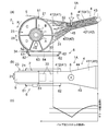
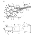
- FIG. 1 is a schematic perspective view showing a first embodiment of an absorbent body manufacturing apparatus according to the present invention.
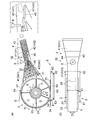
- FIG. 2A is a schematic side view of the manufacturing apparatus shown in FIG. 1 viewed from the side
- FIG. 2B is a schematic view of the manufacturing apparatus shown in FIG. ) Is a graph showing the relationship between the cross-sectional area of the flow path and the position in the spray region in the duct.
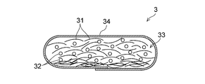
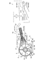
- FIG. 3 is a cross-sectional view of an absorber manufactured by the manufacturing apparatus shown in FIG. 4A is a schematic side view of the manufacturing apparatus according to the first embodiment of the present invention as viewed from the side
- FIG. 4B is a schematic view of the manufacturing apparatus according to the first embodiment as viewed from the top. .
- FIG. 4A is a schematic side view of the manufacturing apparatus according to the first embodiment of the present invention as viewed from the side
- FIG. 4B is a schematic view of the manufacturing apparatus according to the first embodiment as viewed from the top. .
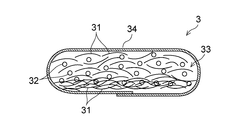
- FIG. 5 is a cross-sectional view of the absorber manufactured by the manufacturing apparatus shown in FIG.
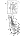
- FIG. 6A is a schematic side view of the manufacturing apparatus according to the second embodiment of the present invention viewed from the side
- FIG. 6B is a schematic view of the manufacturing apparatus of the second embodiment viewed from the top.
- FIG. 7A is a schematic side view of the manufacturing apparatus of the third embodiment of the present invention viewed from the side
- FIG. 7B is a schematic view of the manufacturing apparatus of the third embodiment viewed from the top.
- FIG. 8 is the schematic side view which looked at the manufacturing apparatus of 4th Embodiment of this invention from the side
- FIG. 9 is the schematic side view which looked at the manufacturing apparatus of 5th Embodiment of this invention from the side.
- the absorbent body manufactured by the manufacturing apparatus described in Patent Document 1 is arranged such that the absorbent polymer is partially dispersed in the raw material of the absorbent body, if viewed macroscopically, the absorbent polymer The part which gathered is only the form disperse
- the present invention relates to an absorber manufacturing apparatus that can eliminate the drawbacks of the prior art described above.
- FIG. 1 schematically shows a fiber stacking apparatus 1A according to a first preferred embodiment of the absorbent body manufacturing apparatus of the present invention.
- the fiber stacking apparatus 1 ⁇ / b> A of the first embodiment includes a rotary drum 2 having an accumulation recess 22 in the outer circumferential surface 21 for accumulating the raw material of the absorbent body including the fiber material 31 and the absorbent particles 32, and the outer circumferential surface of the rotary drum 2. And a duct 4 for supplying the raw material of the absorbent body in a scattered state toward 21.
- the fiber stacking apparatus 1 ⁇ / b> A is adjacent to the rotary drum 2 that is rotationally driven in the direction of arrow R, the duct 4 that supplies the raw material of the absorber to the outer peripheral surface 21 of the rotary drum 2, and the downstream side of the duct 4.
- the pressing belt 5 that presses down the absorbent material material pile 33 disposed along the outer peripheral surface 21 of the rotating drum 2 and accumulated in the collecting recess 22, and the vacuum conveyor 6 disposed below the rotating drum 2.
- a fiber material supply unit 7 for supplying the fiber material 31 which is a raw material of the absorber to the duct 4.
- a polymer spray pipe 8 for supplying the absorbent particles 32 into the duct 4 is disposed in the duct 4.
- the rotating drum 2 has a cylindrical shape, and receives power from a motor (not shown) such as a motor, so that members forming the outer peripheral surface 21 rotate around the horizontal axis in the direction of arrow R. To do.
- the drum body 23 located inside the member forming the outer peripheral surface 21 is fixed and does not rotate.
- the rotary drum 2 has an accumulation recess 22 on the outer peripheral surface 21 in which the raw material of the absorber is stacked.
- a plurality of the accumulation recesses 22 are arranged at predetermined intervals in the circumferential direction (2X direction) of the rotary drum 2.
- the 2X direction is the circumferential direction of the rotating drum 2
- the 2Y direction is the width direction of the rotating drum 2 (a direction parallel to the rotation axis of the rotating drum 2).
- the rotary drum 2 has a plurality of mutually independent spaces, and the fiber stacking apparatus 1A has five spaces A to E.
- the spaces A to E are partitioned by a plate provided from the rotating shaft side of the rotating drum 2 toward the outer peripheral surface 21 side.
- An intake fan (not shown) is connected to the rotary drum 2, and the pressure in the partitioned spaces A to E in the rotary drum 2 can be adjusted by driving the intake fan.
- spaces A and B are maintained at a negative pressure.
- the rotating drum 2 corresponds to the suction force of the upstream region (region corresponding to the space A) corresponding to the filter layer forming region made of the fiber material 31 and the mixed layer forming region made of the fiber material 31 and the absorbent particles 32.
- Adjustment means for adjusting the suction force of the downstream region is provided. Accordingly, the suction force in the upstream region (region corresponding to the space A) can be made stronger or weaker than the suction force in the downstream region (region corresponding to the space B).
- the spaces C and D of the rotating drum 2 are normally set to a negative pressure or zero pressure (atmospheric pressure) that is weaker than the space B, and the space E is set to atmospheric pressure (zero pressure) or positive pressure.
- the spaces C and D are made to have a weak negative pressure until the piled product in the stacking recess 22 is transferred onto the vacuum conveyor 6, and the piled product is made to be a stacking recess. It is preferable that the pressure is held in the space 22, but if there is no particular problem in the transportability, the pressure in the spaces C to E is preferably zero in consideration of transferability.
- each accumulation recess 22 is made of a porous member. While the accumulation recess 22 passes over the spaces A and B maintained at negative pressure, the pores of the porous member on the bottom surface 22a of the accumulation recess 22 function as suction holes.
- the porous member those conventionally used in this type of fiber stacking apparatus can be used without particular limitation. For example, many metal members or resin mesh plates or metal or resin plates can be etched or punched. Those having fine pores can be used.
- the raw material of the absorbent body 3 various materials conventionally used for absorbent bodies of absorbent articles such as sanitary napkins, panty liners, and disposable diapers can be used without particular limitation.
- the fiber material 31 that is a raw material of the absorbent body short fibers of cellulose fibers such as pulp fibers, rayon fibers, and cotton fibers, short fibers obtained by hydrophilizing synthetic fibers such as polyethylene, polypropylene, and polyethylene terephthalate are preferable. . These fibers may be used alone or in combination of two or more.
- the fiber material 31 preferably contains pulp fibers, and the ratio of the pulp fibers in the fiber material 31 is preferably 1 to 100% by mass, more preferably 100% by mass.
- Examples of the absorbent particles 32 that are raw materials of the absorber include starch-based, cellulose-based, synthetic polymer, and super-absorbent polymer-based ones.
- Examples of superabsorbent polymers include starch-acrylic acid (salt) graft copolymers, saponified starch-acrylonitrile copolymers, cross-linked sodium carboxymethylcellulose, and acrylic acid (salt) polymers.
- a deodorant, an antibacterial agent, or the like can be used as necessary together with the fiber material 31 and the absorbent particles 32.
- the duct 4 extends from the fiber material supply unit 7 to be described later over the rotary drum 2, and an outer peripheral surface in which the opening on the downstream side of the duct 4 is located in the spaces A and B of the rotary drum 2 maintained at negative pressure. 21 is covered.
- the duct 4 includes a top plate 41 that forms a top surface, a bottom plate 42 that forms a bottom surface, and both side walls 43 and 44 that form both side surfaces. Due to the operation of the intake fan (not shown) of the rotating drum 2, the absorber is directed toward the outer peripheral surface 21 of the rotating drum 2 in the space surrounded by the top plate 41, the bottom plate 42 and the side walls 43, 44 of the duct 4. An air flow for flowing the raw material is generated.
- the top plate 41 of the duct 4 includes an upstream top plate portion 411 located on the upstream side and a downstream top plate located on the downstream side. And plate portion 412.
- the bottom plate 42 of the duct 4 includes an upstream bottom plate portion 421 located on the upstream side and a downstream bottom plate portion 422 located on the downstream side.
- the upstream top plate portion 411 and the upstream bottom plate portion 421 are gradually narrowed from the upstream side toward the downstream side.
- the downstream top plate portion 412 and the downstream bottom plate portion 422 have a constant width from the upstream side toward the downstream side.
- the widths of the downstream top plate portion 412 and the downstream bottom plate portion 422 are the same as the widths of the upstream-side top plate portion 411 and the portion located on the most downstream side of the upstream bottom plate portion 421.
- the distance between the top plate 41 and the bottom plate 42 of the duct 4 is constant between the upstream top plate portion 411 and the upstream bottom plate portion 421.
- the distance between the downstream top plate portion 412 and the downstream bottom plate portion 422 is gradually increased from the upstream top plate portion 411 and the upstream bottom plate portion 421 toward the outer peripheral surface 21 of the rotary drum 2.
- Both side walls 43 and 44 of the duct 4 are provided on the side edges of the top plate 41 composed of the upstream top plate portion 411 and the downstream top plate portion 412, and the upstream bottom plate portion 421 and the downstream bottom plate portion. It is disposed along both side edges of the bottom plate 42 made of 422.
- the polymer spray tube 8 for supplying the absorbent particles 32 into the duct 4 is disposed on the top plate 41 of the duct 4. More specifically, the polymer spray tube 8 is arranged at the downstream end of the upstream top plate portion 411 constituting the top plate 41. The polymer spray tube 8 is arranged so that the lower end thereof is positioned at the upstream end of the partition plate 45 described later.
- the duct 4 having the top plate 41, the bottom plate 42, and both side walls 43 and 44 having the above-described shape is provided in the flow path in the spraying region in which the absorbent particles 32 are sprayed.
- the cross-sectional area is formed smaller than the cross-sectional area of the flow channel located at the uppermost stream of the duct 4 and the cross-sectional area of the flow channel located at the most downstream side of the duct 4.
- the “spreading region” means a region having a certain range on the upstream side or the downstream side from the position where the polymer spraying tube 8 that sprays the absorbent particles 32 is disposed.
- the duct 4 has a top plate 41 in the spraying region in which the absorbent particles 32 are sprayed by the polymer spraying tube 8, as shown in FIGS. 2 (a) to 2 (c).
- the cross-sectional area of the flow path surrounded by the bottom plate 42 and the side walls 43 and 44 is surrounded by the top plate 41, the bottom plate 42 and the side walls 43 and 44 located at the upstream end of the duct 4 closest to the fiber material supply unit 7.
- the cross-sectional area of the flow path is smaller than the cross-sectional area of the flow path surrounded by the top plate 41, the bottom plate 42, and the side walls 43, 44 located at the downstream end of the duct 4 closest to the rotary drum 2. ing.
- the width of the upstream top plate portion 411 of the top plate 41 and the upstream bottom plate portion 421 of the bottom plate 42 gradually decreases from the upstream side toward the downstream side. Therefore, in the upstream-side top plate portion 411 and the upstream-side bottom plate portion 421, the cross-sectional area of the flow path surrounded by the top plate 41, the bottom plate 42, and both side walls 43, 44 gradually decreases from the upstream side toward the downstream side. Yes.
- the distance between the downstream top plate portion 412 of the top plate 41 and the downstream bottom plate portion 422 of the bottom plate 42 gradually increases from the upstream side toward the downstream side
- the cross-sectional area of the flow path surrounded by the top plate 41, the bottom plate 42, and both side walls 43, 44 gradually increases from the upstream side toward the downstream side. Therefore, the cross-sectional area of the flow path in the spraying region in which the absorbent particles 32 are sprayed by the polymer spraying tube 8 disposed at the downstream end of the upstream top plate 411 is relatively small.
- the cross-sectional area of the flow path at the lower end of the polymer spraying tube 8 or the upstream end of the partition plate 45 described later is formed to be the smallest.
- the duct 4 is provided with a partition plate 45 that regulates the flow direction of the absorbent particles 32 supplied therein in the fiber stacking apparatus 1A.
- the partition plate 45 extends from the boundary portion between the upstream top plate portion 411 and the downstream top plate portion 412 toward the rotary drum 2 across both side walls 43 and 44 of the duct 4. Yes. More specifically, the partition plate 45 extends toward the tip of the plate that separates the space A and the space B of the rotary drum 2. Since the partition plate 45 is arranged inside the duct 4, the flow direction of the absorbent particles 32 is regulated, and the flow branches only into the flow of flowing the fiber material 31 and the flow of flowing the fiber material 31 and the absorbent particles 32. Will come to be.
- the presser belt 5 is disposed along the outer peripheral surface 21 of the rotating drum 2 adjacent to the downstream side of the position of the duct 4 of the rotating drum 2 and rotates. It is arranged along the outer peripheral surface 21 located in the spaces C and D set to a negative pressure or zero pressure (atmospheric pressure) that is weaker than the space B of the drum 2.
- the presser belt 5 is an endless breathable or non-breathable belt, is stretched over the roll 51 and the roll 52, and is rotated along with the rotation of the rotary drum 2.
- the pressing belt 5 is a breathable belt, it is preferable that the material in the accumulation recess 22 is not substantially allowed to pass through. Even if the pressure in the spaces C to E is set to atmospheric pressure, the presser belt 5 can hold the piled material in the stacking recess 22 in the stacking recess 22 until it is transferred onto the vacuum conveyor 6.
- the vacuum conveyor 6 is disposed below the rotary drum 2, and is a space E set at a weak positive pressure or zero pressure (atmospheric pressure) of the rotary drum 2. It is arranged on the outer peripheral surface 21 located at the position.
- the vacuum conveyor 6 is opposed to an endless breathable belt 63 spanned between the drive roll 61 and the driven rolls 62 and 62 and the outer peripheral surface 21 located in the space E of the rotary drum 2 with the breathable belt 63 interposed therebetween.
- a vacuum box 64 arranged at the position.
- a core wrap sheet 34 made of tissue paper or liquid permeable nonwoven fabric is introduced.
- the fiber material supply part 7 is a part which supplies the fiber material 31 which is the raw material of an absorber to the duct 4, as shown in FIG.
- the fiber material supply unit 7 includes a defibrator 71. By introducing the sheet-shaped raw fabric 30 of the fiber material 31 into the defibrating machine 71, the original fabric 30 is defibrated, and the defibrated fiber material 31 is supplied to the flow path in the duct 4.
- the suction fans (not shown) connected to the spaces A and B in the rotary drum 2 and the vacuum box 64 are operated to make negative pressure.
- an air flow (vacuum air) is generated in the duct 4 to convey the raw material of the absorber to the outer peripheral surface 21 of the rotary drum 2.
- the rotary drum 2 is rotated and the pressing belt 5 is operated.
- the defibrating machine 71 of the fiber material supply unit 7 is operated to defibrate the sheet-shaped raw material of the fiber material 31, and the defibrated fiber material 31 is supplied to the flow path in the duct 4. Further, the absorbent particles 32 are supplied into the duct 4 by the polymer spray tube 8 disposed on the top plate 41 of the duct 4.
- the duct 4 has a cross-sectional area of the flow path in the spraying region in which the absorbent particles 32 are sprayed in the duct 4 at the most upstream of the duct 4. It is formed smaller than the cross-sectional area of the flow path located and the cross-sectional area of the flow path located on the most downstream side of the duct 4. Therefore, the flow of the defibrated fiber material 31 supplied into the duct 4 is narrowed in the spray area where the absorbent particles 32 are sprayed by the polymer spray pipe 8. In the spraying region, the squeezed fiber material 31 is efficiently mixed with the polymer, and then the flow of the squeezed fiber material 31 rides on the flow spreading toward the most downstream side of the duct 4.
- the absorbent particles 32 dispersed in the dispersion region are efficiently mixed with the fiber material, they are scattered along the flow of the fiber material 31 and are heavier than the fiber material 31 as well as the fiber material 31.
- the absorbent particles 32 are likely to spread throughout the duct 4. That is, the fiber material 31 is confined to the spraying region of the absorbent particles 32, and the fiber material 31 and the absorbent particles 32 are efficiently mixed (entangled), whereby the absorbent particles 32 that have a high specific gravity and are difficult to follow along the airflow.
- the fiber material 31 that is light in specific gravity and easy to follow along with the air flow can be uniformly dispersed in a form that is assisted.
- the cross-sectional area of the flow path surrounded by the top plate 41, the bottom plate 42, and both side walls 43 and 44 is upstream. Since the diameter gradually decreases from the downstream side toward the downstream side, the flow of the defibrated fiber material 31 supplied into the duct 4 is easily restricted in the spraying region in which the absorbent particles 32 are sprayed by the polymer spraying tube 8. ing.
- the cross-sectional area of the flow path surrounded by the top plate 41, the bottom plate 42, and both side walls 43 and 44 is upstream. Since the flow gradually increases toward the downstream side, the flow of the narrowed fiber material 31 easily spreads throughout the thickness direction of the duct 4, and the dispersed absorbent particles 32 follow the flow of the fiber material 31. The fiber material 31 and the absorbent particles 32 are more likely to spread throughout the duct 4.
- the duct 4 is formed in a straight shape without restricting the flow path, and the flow path located at the uppermost stream of the duct 4 is cut off.
- the fiber material sheet width raw fabric width
- the fiber material 31 may be insufficiently defibrated.
- the sheet width (raw fabric width) is narrowed, the consumption speed of the raw fabric is increased and the replacement frequency is increased, resulting in an increase in production loss. Accordingly, it is preferable that the sheet width (raw fabric width) is wide, and therefore it is preferable that the cross-sectional area of the flow path located at the uppermost stream of the duct 4 is also wide.
- the absorbent particles 32 dispersed in the spray region are scattered along the flow of the fiber material 31, and the fiber material 31 and the absorbent particles 32 spread throughout the duct 4, and the accumulation recess 22 on the outer peripheral surface 21 of the rotary drum 2. , The absorbent particles 32 are easily dispersed uniformly in the fiber material 31 and the pile 33 of the absorbent particles 32 in the thickness direction of the accumulation recesses 22.
- a partition plate 45 is arranged in the duct 4. Therefore, a filter layer made of the fiber material 31 is easily formed in a region corresponding to the space A on the upstream side of the rotary drum 2. Further, in a region corresponding to the space B of the rotary drum 2 on the downstream side of the space A, a mixed layer composed of the fiber material 31 and the absorbent particles 32 is easily formed. Thus, in the duct 4 above the partition plate 45, the dispersed absorbent particles 32 are easily scattered along the flow of the fiber material 31, and the fiber material 31 and the absorbent particles 32 are easily spread. .
- the filter layer is for preventing the absorbent particles 32 from being clogged in the mesh pores at the bottom of the accumulation recess 22.
- the rotary drum 2 includes an adjusting unit that adjusts the suction force, for example, by adjusting the balance between the suction force in the region corresponding to the space B and the suction force in the region corresponding to the space A, Furthermore, the fiber material 31 and the absorbent particles 32 can be easily spread in the duct 4 above the partition plate 45. More specifically, for example, if the suction force of the space A is too strong with respect to the suction force of the space B, the filter layer made of the fiber material 31 is excessively formed, and the absorbent particles dispersed in the spraying region accordingly.
- the absorbent particles 32 that cannot be mixed with the fiber material 31 cannot be dispersed and aggregated in the piled product 33.
- the adjusting means by adjusting the balance between the suction force of the region corresponding to the space B and the suction force of the region corresponding to the space A using the adjusting means, the formation of an excessive filter layer is suppressed, and the absorbent particles A sufficient amount of the fiber material 31 to be mixed with the fiber material 32 can be distributed to the spraying region.
- the sprayed absorbent particles 32 are reliably mixed with the fiber material 31, and the duct 4 upwards from the partition plate 45.
- the fiber material 31 and the absorbent particles 32 can be easily spread inside.
- the rotating drum 2 is further rotated and stacked by the presser belt 5 as shown in FIG. It conveys to the vacuum conveyor 6 while pressing the pile 33 in the concave part 22 for use. Then, when the pile 33 in the accumulation recess 22 comes to a position opposite to the vacuum box 64, it is released from the accumulation recess 22 by suction from the vacuum box 64 and is introduced onto the vacuum conveyor 6. It is delivered onto a core wrap sheet 34 made of tissue paper or a liquid-permeable nonwoven fabric.
- both side portions along the conveying direction of the core wrap sheet 34 are folded back, and the upper and lower surfaces of the piled article 33 are covered with the core wrap sheet 34.
- the piled article 33 covered with the core wrap sheet 34 is cut together with the core wrap sheet 34 by cutting means of a cutting device (not shown). In this way, the absorbent body 3 in which the piled material 33 is coated on the core wrap sheet 34 is continuously obtained.
- the absorbent particles 32 are uniformly distributed not only in the width direction of the fiber pile 33 but also in the thickness direction. Is distributed. Therefore, the absorbent body 3 obtained using the fiber stacking apparatus 1A is less likely to cause gel blocking during use, and has high quality suitable as an absorbent body used for absorbent articles such as disposable diapers, sanitary napkins, and incontinence pads. It has become a thing.
- the absorbent particles 32 are uniformly dispersed not only in the width direction of the fiber pile 33 but also in the thickness direction. 3 can be stably produced.
- fiber stacking apparatuses 1B to 1E according to second to fifth embodiments of the present invention will be described.
- differences from the fiber-spreading apparatus 1A of the first embodiment will be mainly described, and the same points will be denoted by the same reference numerals and description thereof will be omitted. .
- the description relating to the fiber stacking apparatus 1A of the first embodiment is applied as appropriate.
- the effects of the fiber stacking devices 1B to 1E of the second to fifth embodiments will be described with respect to differences from the effects of the fiber stacking device 1A of the first embodiment. This is the same as the effect, and the description of the effect of the fiber stacking apparatus 1A is applied as appropriate.
- the fiber stacking apparatus 1A As shown in FIGS. 4A and 4B, the fiber stacking apparatus 1A according to the first embodiment described above has a top plate 41 in the duct 4 according to the characteristics of the defibrator 71 of the fiber material supply unit 7.
- the amount of fiber material 31 that has been defibrated may increase on the bottom plate 42 side (downward) in the thickness direction with the bottom plate 42.
- fibers are formed in a region corresponding to the space A on the upstream side of the rotary drum 2.
- the filter layer made of the material 31 may be formed excessively. As shown in FIG.
- the piled product 33 of the absorbent body 3 obtained under such circumstances has an excessively formed filter layer of the fiber material 31 made of only the fiber material 31 in the thickness direction downward, and in the spreading region. Since the fiber material 31 to be mixed with the dispersed absorbent particles 32 is reduced, the absorbent particles 32 that cannot be mixed with the fiber material 31 are not completely dispersed and are present in an aggregated state in the piled fabric 33. End up. Even if the suction force of the space B is adjusted to be stronger than the suction force of the space A, the absorbent particles 32 having a high specific gravity cannot be mixed with the flow of the fiber material 31 having a low specific gravity in the spray region above the partition plate 45. Therefore, the absorbent particles 32 may not be sufficiently dispersed.
- the stacked fiber In order to increase the amount of the fiber material 31 flowing in the spraying region and concentrate the fiber material 31 near the tip of the spraying tube so that it can be easily mixed with the absorbent particles 32, the stacked fiber according to the second embodiment described below.
- the fiber stacking apparatus 1E of the apparatus 1B to the fifth embodiment is effective.
- the fiber stacking apparatus 1B of the second embodiment has the fiber material 31 on the upstream side of the spraying region in which the absorbent particles 32 are sprayed in the duct 4.
- Means for correcting the flow direction and concentrating the fiber material 31 in the spraying region are provided.
- the fiber stacking apparatus 1 ⁇ / b> B of the second embodiment has a correction guide 46 for correcting the flow direction of the fiber material 31 inside the duct 4.
- the correction guide 46 is located in the upstream top plate portion 411 of the top plate 41 of the duct 4 and the upstream bottom plate portion 421 of the bottom plate 42, and extends upstream of the bottom plate 42 across both side walls 43, 44 of the duct 4.
- the bottom plate portion 421 extends from the upper surface toward the downstream side.
- the correction guide 46 is arranged such that the lower end of the polymer spray tube 8 or the upstream end of the partition plate 45 is positioned on the extended line of the upper surface. Since the fiber stacking apparatus 1B is provided with the guide 46, there is also an advantage that arbitrary control can be performed by changing the guide position according to the conditions.
- the duct 4 has a cross-sectional area of the flow path in the spraying region in which the absorbent particles 32 are sprayed, as in the fiber stacking apparatus 1A of the first embodiment.
- the cross-sectional area of the flow channel located at the uppermost stream of the duct 4 and the cross-sectional area of the flow channel located at the most downstream side of the duct 4 are formed smaller. Therefore, the flow of the defibrated fiber material 31 supplied into the duct 4 is narrowed in the spray area where the absorbent particles 32 are sprayed by the polymer spray pipe 8.
- the straightening guide 46 for correcting the flow direction of the fiber material 31 is provided inside the duct 4, the fiber material that has been defibrated toward the spraying region in which the absorbent particles 32 are sprayed.
- the flow of 31 is concentrated. Therefore, when the flow of the squeezed fiber material 31 collides with the absorbent particles 32 dispersed in the spray region and becomes easy to be mixed, the absorbent particles 32 are released when released toward the most downstream side of the duct 4.
- the absorbent particles 32 that are further scattered along the flow of the fiber material 31 and are heavier than the fiber material 31 as well as the fiber material 31 are more likely to spread throughout the duct 4.
- the pile 33 of the absorbent body 3 obtained using the pile apparatus 1 ⁇ / b> B is similar to the pile 33 of the absorbent body 3 obtained using the pile apparatus 1 ⁇ / b> A of the first embodiment.
- the absorbent particles 32 are uniformly dispersed not only in the width direction of the piled product 33 but also in the thickness direction. Accordingly, gel blocking is unlikely to occur in the absorbent body 3 during use, and the absorbent body 3 is of a high quality suitable as an absorbent body used in absorbent articles such as disposable diapers, sanitary napkins, and incontinence pads.
- the absorbent particles 32 can stably distribute the absorbent body 3 uniformly dispersed not only in the width direction of the fiber stack 33 but also in the thickness direction. Can be manufactured.
- the fiber stacking apparatus 1C of the third embodiment has fibers on the upstream side of the spraying region in which the absorbent particles 32 are sprayed in the duct 4.
- Means for correcting the flow direction of the material 31 and concentrating the fiber material 31 in the spraying region is provided.
- the upstream-side bottom plate portion 421 of the bottom plate 42 of the duct 4 is arranged to be inclined. More specifically, the upstream bottom plate portion 421 is arranged so that the lower end of the polymer spray tube 8 or the upstream end portion of the partition plate 45 is positioned on the extended line of the upper surface thereof. 421 is a means for concentrating the fiber material 31 in the spraying region.
- the distance between the top plate 41 and the bottom plate 42 is as shown in FIG. 7 (a).
- the distance between the plate portion 411 and the upstream bottom plate portion 421 is gradually narrowed toward the spraying region, and the distance between the downstream top plate portion 412 and the downstream bottom plate portion 422 is the upstream top plate portion 411 and The width gradually increases from the upstream bottom plate portion 421 toward the outer peripheral surface 21 of the rotary drum 2.
- the downstream end of the upstream bottom plate 421 is located upstream of the end of the partition plate 45, and as shown in FIG.7 (b), the upstream top plate 411 and the upstream bottom plate 421 are:
- the width gradually decreases from the upstream side toward the downstream side. For this reason, the cross-sectional area of the flow path in the spraying region in which the absorbent particles 32 are sprayed by the polymer spraying tube 8 disposed at the downstream end of the upstream top plate 411 is further reduced. Since the space
- a dead space is generated in the lower portion, so that eddy currents may occur or pulp powder may gradually accumulate.
- the fiber stacking apparatus 1C is improved so as not to have such a dead space.
- the duct 4 has a cross-sectional area of the flow path in the spraying region in which the absorbent particles 32 are sprayed, as compared with the fiber stacking apparatus 1A of the first embodiment.
- the cross-sectional area of the flow path located at the uppermost stream of the duct 4 and the cross-sectional area of the flow path located at the most downstream side of the duct 4 are further reduced. Therefore, the flow of the defibrated fiber material 31 supplied into the duct 4 is narrowed in the spray area where the absorbent particles 32 are sprayed by the polymer spray pipe 8.
- the flow direction of the fiber material 31 is corrected by the upstream bottom plate portion 421 in the duct 4, and the fiber material 31 is defibrated toward the spraying region where the absorbent particles 32 are sprayed. Is concentrated. Therefore, the flow of the squeezed fiber material 31 easily collides with the absorbent particles 32 dispersed in the application region, and the absorbent particles 32 are released from the fiber material 31 when released toward the most downstream side of the duct 4. The absorbent particles 32 that are further scattered along the flow and are heavier than the fiber material 31 as well as the fiber material 31 are more likely to spread throughout the duct 4.
- the pile 33 of the absorbent body 3 obtained using the fiber pile device 1 ⁇ / b> C is similar to the pile 33 of the absorbent body 3 obtained using the fiber pile device 1 ⁇ / b> A of the first embodiment.
- the absorbent particles 32 are uniformly dispersed not only in the width direction of the piled product 33 but also in the thickness direction. Accordingly, gel blocking is unlikely to occur in the absorbent body 3 during use, and the absorbent body 3 is of a high quality suitable as an absorbent body used in absorbent articles such as disposable diapers, sanitary napkins, and incontinence pads.
- the absorbent particles 32 can stably disperse the uniformly dispersed absorbent body 3 not only in the width direction but also in the thickness direction of the fiber stack 33. Can be manufactured.
- the fiber stacking apparatus 1D of the fourth embodiment corrects the flow direction of the fiber material 31 upstream of the spraying region in which the absorbent particles 32 are sprayed in the duct 4, Means for concentrating the fiber material 31 in the spraying region is provided.
- the duct 4 has a correction guide 47 for correcting the flow direction of the fiber material 31 inside.
- the correction guide 47 is located in the upstream top plate portion 411 of the top plate 41 of the duct 4 and the upstream bottom plate portion 421 of the bottom plate 42, and extends upstream of the bottom plate 42 across both side walls 43, 44 of the duct 4.
- the bottom plate portion 421 extends from the upper surface toward the downstream side. As shown in FIG.
- the correction guide 47 has a shape that is narrowed to the center in the width direction at the downstream end. That is, the correction guide 47 has a shape in which both side portions in the width direction are pushed up at the downstream end portion thereof and are narrowed down to the center portion in the width direction.
- the correction guide 47 is arranged so that the lower end of the polymer spray tube 8 or the upstream end of the partition plate 45 is positioned on the extended line of the upper surface of the central portion in the width direction at the downstream end.
- the duct 4 has a cross-sectional area of the flow path in the spraying region in which the absorbent particles 32 are sprayed, as in the fiber stacking apparatus 1A of the first embodiment.
- the cross-sectional area of the flow channel located at the uppermost stream of the duct 4 and the cross-sectional area of the flow channel located at the most downstream side of the duct 4 are formed smaller. Therefore, the flow of the defibrated fiber material 31 supplied into the duct 4 is narrowed in the spray area where the absorbent particles 32 are sprayed by the polymer spray pipe 8.
- the straightening guide 47 for correcting the flow direction of the fiber material 31 is provided inside the duct 4, the solution is directed toward the central portion in the width direction of the spraying region where the absorbent particles 32 are sprayed.
- the flow of the fibrillated fiber material 31 is concentrated. Therefore, the flow of the squeezed fiber material 31 easily collides with the absorbent particles 32 dispersed in the application region, and the absorbent particles 32 are released from the fiber material 31 when released toward the most downstream side of the duct 4.
- the absorbent particles 32 that are further scattered along the flow and are heavier than the fiber material 31 and are heavier than the fiber material 31 are more likely to spread throughout the duct 4, and the fiber material 31 and the absorbent particles 32 are more efficiently mixed. Is done.
- the pile 33 of the absorbent body 3 obtained using the fiber pile device 1 ⁇ / b> C is similar to the pile 33 of the absorbent body 3 obtained using the fiber pile device 1 ⁇ / b> A of the first embodiment.
- the absorbent particles 32 are uniformly dispersed not only in the width direction of the piled product 33 but also in the thickness direction. Accordingly, gel blocking is unlikely to occur in the absorbent body 3 during use, and the absorbent body 3 is of a high quality suitable as an absorbent body used in absorbent articles such as disposable diapers, sanitary napkins, and incontinence pads.
- the absorbent particles 32 can stably disperse the uniformly dispersed absorbent body 3 not only in the width direction but also in the thickness direction of the fiber stack 33. Can be manufactured.
- the fiber stacking apparatus 1E of the fifth embodiment corrects the flow direction of the fiber material 31 upstream of the spraying region in which the absorbent particles 32 are sprayed in the duct 4, Means for concentrating the fiber material 31 in the spraying region is provided.
- the duct 4 has an air blow device 48 that is an air discharge means for correcting the flow direction of the fiber material on the upstream side of the spraying region, The fiber material 31 is concentrated in the spray area by the air discharge means (air blow device) 48.
- the air blowing port is arranged on the upstream bottom plate part 421 of the bottom plate 42 of the duct 4, and the air blown from the blowing port is the lower end of the polymer spray pipe 8 or the upstream side of the partition plate 45. It is arranged to go to the end of the.
- the air blow device 48 is connected to an air source (not shown) by a conduit 481 as shown in FIG.
- the duct 4 has a cross-sectional area of the flow path in the spraying region in which the absorbent particles 32 are sprayed, as in the fiber stacking apparatus 1A of the first embodiment.
- the cross-sectional area of the flow channel located at the uppermost stream of the duct 4 and the cross-sectional area of the flow channel located at the most downstream side of the duct 4 are formed smaller. Therefore, the flow of the defibrated fiber material 31 supplied into the duct 4 is narrowed in the spray area where the absorbent particles 32 are sprayed by the polymer spray pipe 8.
- the air discharge means (air blow apparatus) 48 for correcting the flow direction of the fiber material 31 is provided inside the duct 4, it is directed toward the spraying area where the absorbent particles 32 are sprayed.
- the flow of the fibrillated fiber material 31 is concentrated. Therefore, the flow of the squeezed fiber material 31 easily collides with the absorbent particles 32 dispersed in the application region, and the absorbent particles 32 are released from the fiber material 31 when released toward the most downstream side of the duct 4.
- the absorbent particles 32 that are further scattered along the flow and are heavier than the fiber material 31 as well as the fiber material 31 are more likely to spread throughout the duct 4.
- the pile 33 of the absorbent body 3 obtained using the pile apparatus 1E is similar to the pile 33 of the absorbent body 3 obtained using the pile apparatus 1A of the first embodiment.
- the absorbent particles 32 are uniformly dispersed not only in the width direction of the piled product 33 but also in the thickness direction. Accordingly, gel blocking is unlikely to occur in the absorbent body 3 during use, and the absorbent body 3 is of a high quality suitable as an absorbent body used in absorbent articles such as disposable diapers, sanitary napkins, and incontinence pads.
- the absorbent particles 32 can stably disperse the uniformly dispersed absorbent body 3 not only in the width direction but also in the thickness direction of the fiber stack 33. Can be manufactured.
- the manufacturing apparatus of the absorbent body of the present invention is not limited to the fiber stacking apparatuses 1A to 1E of the first to fifth embodiments described above, and can be changed as appropriate.
- the constituent elements in the fiber stacking apparatuses 1A to 1E of the first to fifth embodiments described above can be appropriately combined and implemented within a range that does not impair the gist of the present invention.
- the upstream top plate portion 411 of the top plate 41 and the upstream bottom plate portion 421 of the bottom plate 42 in the duct 4 are directed from the upstream side toward the downstream side.
- the width is gradually narrowed, it may be narrowed in stages.
- the distance between the downstream top plate portion 412 of the top plate 41 and the downstream bottom plate portion 422 of the bottom plate 42 in the duct 4 is from the upstream side to the downstream side. Although it becomes gradually wider toward, it may be gradually increased.
- the shape of the piled product 33 to be manufactured may be flexibly changed by changing the shape of the concave portion 22 for accumulation.
- the absorbent body produced in the present invention is preferably used as an absorbent body for absorbent articles.
- the absorbent article is mainly used to absorb and retain body fluids excreted from the body such as urine and menstrual blood.
- Absorbent articles include, for example, disposable diapers, sanitary napkins, incontinence pads, panty liners, etc., but are not limited to these, and widely include articles used to absorb liquid discharged from the human body. To do.
- a rotary drum having an accumulation recess for collecting the raw material of the absorbent body including the fiber material and the absorbent particles on the outer peripheral surface; and a duct for supplying the raw material of the absorber in a scattered state toward the outer peripheral surface of the rotary drum;
- An absorbent body manufacturing apparatus comprising: In the duct, the cross-sectional area of the flow path in the spraying region in which the absorbent particles are dispersed in the duct is greater than the cross-sectional area of the flow path located in the uppermost stream of the duct and the cross-sectional area of the flow path located in the most downstream.
- the manufacturing apparatus of the absorber which is also formed small.
- the said duct is an manufacturing apparatus of the absorber as described in said ⁇ 1> which has a means which corrects the flow direction of the said fiber material, and concentrates this fiber material on this spreading area upstream from the said spreading area.
- ⁇ 4> The apparatus for manufacturing an absorbent body according to any one of ⁇ 1> to ⁇ 3>, wherein the correction guide has a shape narrowed to a central portion in the width direction at an end portion on the downstream side thereof.
- the duct has air discharge means for correcting the flow direction of the fiber material upstream from the spray area, and the fiber material is concentrated in the spray area by the air discharge means.
- the absorbent body manufacturing apparatus according to any one of the above items ⁇ 1> to ⁇ 5>, comprising an adjusting means for adjusting.
- ⁇ 7> The absorbent manufacturing apparatus according to any one of ⁇ 1> to ⁇ 6>, wherein the absorbent manufacturing apparatus is a fiber stacking apparatus.
- ⁇ 8> The absorbent manufacturing apparatus according to any one of ⁇ 1> to ⁇ 7>, wherein a plurality of the accumulation recesses are arranged at a predetermined interval in a circumferential direction (2X direction) of the rotating drum.
- the rotating drum has a plurality of mutually independent spaces inside, An intake fan is connected to the rotating drum, and the pressure of the space partitioned in the rotating drum can be adjusted by driving the intake fan,
- the fiber material include short fibers of cellulose fibers such as pulp fibers, rayon fibers, and cotton fibers, short fibers obtained by hydrophilizing synthetic fibers such as polyethylene, polypropylene, and polyethylene terephthalate.
- ⁇ 11> The absorbent production apparatus according to any one of ⁇ 1> to ⁇ 10>, wherein starch, cellulose, synthetic polymer, or superabsorbent polymer is used as the absorbent particles.
- ⁇ 12> The absorbent manufacturing apparatus according to any one of ⁇ 1> to ⁇ 11>, wherein the absorbent particles are heavier than the fiber material.
- the absorber manufacturing apparatus includes a fiber material supply unit that supplies the fiber material to the duct.
- the duct extends from the fiber material supply unit to the rotating drum, and an opening on the downstream side of the duct covers an outer peripheral surface located in the space of the rotating drum maintained at a negative pressure.
- ⁇ 14> The manufacture of the absorber according to any one of ⁇ 1> to ⁇ 13>, wherein the duct includes a top plate that forms a top surface, a bottom plate that forms a bottom surface, and both side walls that form both side surfaces. apparatus.
- the top plate of the duct consists of an upstream top plate portion located on the upstream side and a downstream top plate portion located on the downstream side
- the duct bottom plate is composed of an upstream bottom plate portion located on the upstream side and a downstream bottom plate portion located on the downstream side
- the upstream top plate portion and the upstream bottom plate portion are gradually narrowed from the upstream side toward the downstream side, and the downstream top plate portion and the downstream bottom plate portion are from the upstream side to the downstream side.
- the width is constant toward the ⁇ 1> to ⁇ 14, wherein the downstream top plate portion and the downstream bottom plate portion have the same width as that of a portion located on the most downstream side of the upstream top plate portion and the upstream bottom plate portion.
- the distance between the top plate of the duct and the bottom plate of the duct is such that the distance between the upstream top plate portion and the upstream bottom plate portion is constant, and the distance between the downstream top plate portion and the downstream bottom plate portion is The apparatus for manufacturing an absorbent body according to ⁇ 14> or ⁇ 15>, wherein the interval gradually increases from the upstream top plate portion and the upstream bottom plate portion toward the outer peripheral surface of the rotary drum.
- a polymer spray pipe for supplying the absorbent particles into the duct is disposed on a top plate of the duct.
- the said polymer dispersion tube is a manufacturing apparatus of the absorber as described in said ⁇ 17> distribute
- the duct includes a partition plate that regulates the flow direction of the absorbent particles supplied therein,
- the said polymer dispersion tube is a manufacturing apparatus of the absorber as described in said ⁇ 17> or ⁇ 18> arrange
- ⁇ 20> The absorbent body manufacturing apparatus according to ⁇ 19>, wherein the cross-sectional area of the flow path at the lower end of the polymer spray pipe or the upstream end of the partition plate is the smallest in the spray region. . ⁇ 21> Inside the duct, on the upstream side of the spray area, has a correction guide for correcting the flow direction of the fiber material, The straightening guide is located in the upstream top plate portion of the top plate of the duct and the upstream bottom plate portion of the bottom plate of the duct and across the both side walls of the duct, the upstream side plate portion of the duct bottom plate.
- the absorbent manufacturing apparatus according to any one of ⁇ 1> to ⁇ 20> which extends from the upper surface toward the downstream side. ⁇ 22>
- the fibrous material is confined to the spraying region of the absorbent particles, and the fibrous material and the absorbent particles are efficiently mixed (entangled), whereby the absorbent particles having a high specific gravity and difficult to follow the air flow are obtained. It is possible to disperse uniformly in a form that is assisted by a fiber material that has a low specific gravity and is easy to follow along the air flow in terms of shape. As a result, gel blocking is unlikely to occur, and an absorbent body that can fully utilize the absorbent performance of the absorbent body can be stably produced.
Landscapes
- Health & Medical Sciences (AREA)
- Engineering & Computer Science (AREA)
- Vascular Medicine (AREA)
- Epidemiology (AREA)
- Biomedical Technology (AREA)
- Heart & Thoracic Surgery (AREA)
- Manufacturing & Machinery (AREA)
- Life Sciences & Earth Sciences (AREA)
- Animal Behavior & Ethology (AREA)
- General Health & Medical Sciences (AREA)
- Public Health (AREA)
- Veterinary Medicine (AREA)
- Absorbent Articles And Supports Therefor (AREA)
Priority Applications (1)
| Application Number | Priority Date | Filing Date | Title |
|---|---|---|---|
| CN201480067570.0A CN105813609B (zh) | 2013-12-13 | 2014-11-19 | 吸收体的制造装置 |
Applications Claiming Priority (2)
| Application Number | Priority Date | Filing Date | Title |
|---|---|---|---|
| JP2013-258044 | 2013-12-13 | ||
| JP2013258044A JP5953296B2 (ja) | 2013-12-13 | 2013-12-13 | 吸収体の製造装置 |
Publications (1)
| Publication Number | Publication Date |
|---|---|
| WO2015087674A1 true WO2015087674A1 (ja) | 2015-06-18 |
Family
ID=53370988
Family Applications (1)
| Application Number | Title | Priority Date | Filing Date |
|---|---|---|---|
| PCT/JP2014/080611 Ceased WO2015087674A1 (ja) | 2013-12-13 | 2014-11-19 | 吸収体の製造装置 |
Country Status (3)
| Country | Link |
|---|---|
| JP (1) | JP5953296B2 (enExample) |
| CN (1) | CN105813609B (enExample) |
| WO (1) | WO2015087674A1 (enExample) |
Families Citing this family (8)
| Publication number | Priority date | Publication date | Assignee | Title |
|---|---|---|---|---|
| JP6176685B2 (ja) * | 2016-01-28 | 2017-08-09 | 大王製紙株式会社 | 吸収性物品の製造方法 |
| JP6864466B2 (ja) * | 2016-12-15 | 2021-04-28 | 花王株式会社 | 吸収体の製造装置 |
| CN108236542B (zh) | 2016-12-27 | 2023-03-10 | 大王制纸株式会社 | 吸收性物品的制造方法和吸收性物品 |
| JP6174286B1 (ja) * | 2017-05-22 | 2017-08-02 | 大王製紙株式会社 | 吸収性物品 |
| DE112017007901T5 (de) * | 2017-10-03 | 2020-05-14 | Kao Corporation | Verfahren zur herstellung eines absorptionskörpers und vorrichtung zur herstellung eines absorptionskörpers |
| RU2750537C1 (ru) * | 2017-11-28 | 2021-06-29 | Као Корпорейшн | Способ изготовления впитывающего компонента и способ изготовления впитывающего изделия |
| EP4316435A4 (en) * | 2021-03-29 | 2025-03-12 | Shanghai Zhilian Precision Machinery Co., Ltd. | Flexible demolding device, core molding device, and core forming method |
| CN113151982B (zh) * | 2021-04-28 | 2023-06-27 | 上海智联精工机械有限公司 | 刚性脱模成型装置 |
Citations (7)
| Publication number | Priority date | Publication date | Assignee | Title |
|---|---|---|---|---|
| JP2006500155A (ja) * | 2002-09-26 | 2006-01-05 | キンバリー クラーク ワールドワイド インコーポレイテッド | 複数の重ね合わされた繊維層を持つ物品を空気形成する方法及び装置 |
| JP2006016727A (ja) * | 2004-07-01 | 2006-01-19 | Kao Corp | 積繊体製造装置 |
| JP2006115999A (ja) * | 2004-10-20 | 2006-05-11 | Daio Paper Corp | 吸収体の製造装置 |
| JP2006141615A (ja) * | 2004-11-18 | 2006-06-08 | Uni Charm Corp | 吸液性芯材成型ドラム |
| JP2009114555A (ja) * | 2007-11-01 | 2009-05-28 | Kao Corp | 堆積体の製造方法及び製造装置 |
| JP2012139381A (ja) * | 2010-12-28 | 2012-07-26 | Unicharm Corp | 体液吸収性のコアを含む体液吸収性物品、およびそのコアを製造する方法 |
| JP2012147957A (ja) * | 2011-01-19 | 2012-08-09 | Unicharm Corp | 吸収体の製造装置 |
Family Cites Families (4)
| Publication number | Priority date | Publication date | Assignee | Title |
|---|---|---|---|---|
| JP4325994B2 (ja) * | 2003-07-31 | 2009-09-02 | 株式会社リブドゥコーポレーション | シート状体の製造方法および装置並びにシート状体を用いた使い捨て吸収性物品の製造方法 |
| US20060276092A1 (en) * | 2005-06-01 | 2006-12-07 | Topolkaraev Vasily A | Fibers and nonwovens with improved properties |
| CN101400328B (zh) * | 2006-04-27 | 2012-05-09 | Sca卫生产品股份公司 | 在同步定位至少一个基本连续材料织物中使用的、用于检测同步标记的方法和装置 |
| CN102665626B (zh) * | 2009-12-04 | 2014-07-23 | 花王株式会社 | 吸收体的制造方法和制造装置 |
-
2013
- 2013-12-13 JP JP2013258044A patent/JP5953296B2/ja active Active
-
2014
- 2014-11-19 CN CN201480067570.0A patent/CN105813609B/zh active Active
- 2014-11-19 WO PCT/JP2014/080611 patent/WO2015087674A1/ja not_active Ceased
Patent Citations (7)
| Publication number | Priority date | Publication date | Assignee | Title |
|---|---|---|---|---|
| JP2006500155A (ja) * | 2002-09-26 | 2006-01-05 | キンバリー クラーク ワールドワイド インコーポレイテッド | 複数の重ね合わされた繊維層を持つ物品を空気形成する方法及び装置 |
| JP2006016727A (ja) * | 2004-07-01 | 2006-01-19 | Kao Corp | 積繊体製造装置 |
| JP2006115999A (ja) * | 2004-10-20 | 2006-05-11 | Daio Paper Corp | 吸収体の製造装置 |
| JP2006141615A (ja) * | 2004-11-18 | 2006-06-08 | Uni Charm Corp | 吸液性芯材成型ドラム |
| JP2009114555A (ja) * | 2007-11-01 | 2009-05-28 | Kao Corp | 堆積体の製造方法及び製造装置 |
| JP2012139381A (ja) * | 2010-12-28 | 2012-07-26 | Unicharm Corp | 体液吸収性のコアを含む体液吸収性物品、およびそのコアを製造する方法 |
| JP2012147957A (ja) * | 2011-01-19 | 2012-08-09 | Unicharm Corp | 吸収体の製造装置 |
Also Published As
| Publication number | Publication date |
|---|---|
| CN105813609B (zh) | 2019-11-08 |
| JP2015112393A (ja) | 2015-06-22 |
| CN105813609A (zh) | 2016-07-27 |
| JP5953296B2 (ja) | 2016-07-20 |
Similar Documents
| Publication | Publication Date | Title |
|---|---|---|
| JP5953296B2 (ja) | 吸収体の製造装置 | |
| JP5969104B2 (ja) | 吸収体の製造方法 | |
| CN111093576B (zh) | 吸收体的制造方法和吸收体的制造装置 | |
| JP2017046928A (ja) | 吸収体の製造方法 | |
| JP6663893B2 (ja) | 吸収体の製造方法 | |
| JP6774308B2 (ja) | 吸収体の製造方法及び製造装置 | |
| JP6982453B2 (ja) | 吸収体の製造方法及び吸収体の製造装置 | |
| JP2019063371A (ja) | 吸収体の製造方法及び吸収体の製造装置 | |
| CN110636821B (zh) | 吸收体和吸收性物品的制造方法、以及吸收体和吸收性物品的制造装置 | |
| JP2019063368A (ja) | 吸収体の製造方法 | |
| JP2019063372A (ja) | 吸収体の製造方法 | |
| JP2016104054A (ja) | 吸収体の製造装置 | |
| JP6699980B2 (ja) | 吸収体の製造方法及び吸収体の製造装置 | |
| JP6603830B2 (ja) | 吸収体の製造方法 | |
| JP7425073B2 (ja) | 吸収体の製造装置および方法 | |
| WO2019106731A1 (ja) | 吸収体の製造方法及び吸収性物品の製造方法 | |
| JP6647009B2 (ja) | 吸収体の製造装置及び製造方法 | |
| RU2774349C2 (ru) | Способ изготовления впитывающего элемента | |
| JP6864466B2 (ja) | 吸収体の製造装置 | |
| JP6822246B2 (ja) | 吸収体、該吸収体を備える吸収性物品、前記吸収体の製造方法および製造装置 |
Legal Events
| Date | Code | Title | Description |
|---|---|---|---|
| 121 | Ep: the epo has been informed by wipo that ep was designated in this application |
Ref document number: 14869617 Country of ref document: EP Kind code of ref document: A1 |
|
| NENP | Non-entry into the national phase |
Ref country code: DE |
|
| WWE | Wipo information: entry into national phase |
Ref document number: IDP00201603963 Country of ref document: ID |
|
| 122 | Ep: pct application non-entry in european phase |
Ref document number: 14869617 Country of ref document: EP Kind code of ref document: A1 |