WO2015083735A1 - トナー、画像形成装置、及びプロセスカートリッジ - Google Patents
トナー、画像形成装置、及びプロセスカートリッジ Download PDFInfo
- Publication number
- WO2015083735A1 WO2015083735A1 PCT/JP2014/081965 JP2014081965W WO2015083735A1 WO 2015083735 A1 WO2015083735 A1 WO 2015083735A1 JP 2014081965 W JP2014081965 W JP 2014081965W WO 2015083735 A1 WO2015083735 A1 WO 2015083735A1
- Authority
- WO
- WIPO (PCT)
- Prior art keywords
- toner
- latent image
- image carrier
- intermediate transfer
- liquid
- Prior art date
- Legal status (The legal status is an assumption and is not a legal conclusion. Google has not performed a legal analysis and makes no representation as to the accuracy of the status listed.)
- Ceased
Links
Images








Classifications
-
- G—PHYSICS
- G03—PHOTOGRAPHY; CINEMATOGRAPHY; ANALOGOUS TECHNIQUES USING WAVES OTHER THAN OPTICAL WAVES; ELECTROGRAPHY; HOLOGRAPHY
- G03G—ELECTROGRAPHY; ELECTROPHOTOGRAPHY; MAGNETOGRAPHY
- G03G21/00—Arrangements not provided for by groups G03G13/00 - G03G19/00, e.g. cleaning, elimination of residual charge
-
- G—PHYSICS
- G03—PHOTOGRAPHY; CINEMATOGRAPHY; ANALOGOUS TECHNIQUES USING WAVES OTHER THAN OPTICAL WAVES; ELECTROGRAPHY; HOLOGRAPHY
- G03G—ELECTROGRAPHY; ELECTROPHOTOGRAPHY; MAGNETOGRAPHY
- G03G15/00—Apparatus for electrographic processes using a charge pattern
- G03G15/14—Apparatus for electrographic processes using a charge pattern for transferring a pattern to a second base
- G03G15/16—Apparatus for electrographic processes using a charge pattern for transferring a pattern to a second base of a toner pattern, e.g. a powder pattern, e.g. magnetic transfer
- G03G15/1605—Apparatus for electrographic processes using a charge pattern for transferring a pattern to a second base of a toner pattern, e.g. a powder pattern, e.g. magnetic transfer using at least one intermediate support
- G03G15/161—Apparatus for electrographic processes using a charge pattern for transferring a pattern to a second base of a toner pattern, e.g. a powder pattern, e.g. magnetic transfer using at least one intermediate support with means for handling the intermediate support, e.g. heating, cleaning, coating with a transfer agent
-
- B—PERFORMING OPERATIONS; TRANSPORTING
- B08—CLEANING
- B08B—CLEANING IN GENERAL; PREVENTION OF FOULING IN GENERAL
- B08B1/00—Cleaning by methods involving the use of tools
- B08B1/10—Cleaning by methods involving the use of tools characterised by the type of cleaning tool
- B08B1/16—Rigid blades, e.g. scrapers; Flexible blades, e.g. wipers
- B08B1/165—Scrapers
-
- G—PHYSICS
- G03—PHOTOGRAPHY; CINEMATOGRAPHY; ANALOGOUS TECHNIQUES USING WAVES OTHER THAN OPTICAL WAVES; ELECTROGRAPHY; HOLOGRAPHY
- G03G—ELECTROGRAPHY; ELECTROPHOTOGRAPHY; MAGNETOGRAPHY
- G03G21/00—Arrangements not provided for by groups G03G13/00 - G03G19/00, e.g. cleaning, elimination of residual charge
- G03G21/0005—Arrangements not provided for by groups G03G13/00 - G03G19/00, e.g. cleaning, elimination of residual charge for removing solid developer or debris from the electrographic recording medium
- G03G21/0011—Arrangements not provided for by groups G03G13/00 - G03G19/00, e.g. cleaning, elimination of residual charge for removing solid developer or debris from the electrographic recording medium using a blade; Details of cleaning blades, e.g. blade shape, layer forming
-
- G—PHYSICS
- G03—PHOTOGRAPHY; CINEMATOGRAPHY; ANALOGOUS TECHNIQUES USING WAVES OTHER THAN OPTICAL WAVES; ELECTROGRAPHY; HOLOGRAPHY
- G03G—ELECTROGRAPHY; ELECTROPHOTOGRAPHY; MAGNETOGRAPHY
- G03G9/00—Developers
- G03G9/08—Developers with toner particles
- G03G9/0802—Preparation methods
- G03G9/0804—Preparation methods whereby the components are brought together in a liquid dispersing medium
-
- G—PHYSICS
- G03—PHOTOGRAPHY; CINEMATOGRAPHY; ANALOGOUS TECHNIQUES USING WAVES OTHER THAN OPTICAL WAVES; ELECTROGRAPHY; HOLOGRAPHY
- G03G—ELECTROGRAPHY; ELECTROPHOTOGRAPHY; MAGNETOGRAPHY
- G03G9/00—Developers
- G03G9/08—Developers with toner particles
- G03G9/0802—Preparation methods
- G03G9/0817—Separation; Classifying
-
- G—PHYSICS
- G03—PHOTOGRAPHY; CINEMATOGRAPHY; ANALOGOUS TECHNIQUES USING WAVES OTHER THAN OPTICAL WAVES; ELECTROGRAPHY; HOLOGRAPHY
- G03G—ELECTROGRAPHY; ELECTROPHOTOGRAPHY; MAGNETOGRAPHY
- G03G9/00—Developers
- G03G9/08—Developers with toner particles
- G03G9/0819—Developers with toner particles characterised by the dimensions of the particles
-
- G—PHYSICS
- G03—PHOTOGRAPHY; CINEMATOGRAPHY; ANALOGOUS TECHNIQUES USING WAVES OTHER THAN OPTICAL WAVES; ELECTROGRAPHY; HOLOGRAPHY
- G03G—ELECTROGRAPHY; ELECTROPHOTOGRAPHY; MAGNETOGRAPHY
- G03G9/00—Developers
- G03G9/08—Developers with toner particles
- G03G9/0827—Developers with toner particles characterised by their shape, e.g. degree of sphericity
-
- G—PHYSICS
- G03—PHOTOGRAPHY; CINEMATOGRAPHY; ANALOGOUS TECHNIQUES USING WAVES OTHER THAN OPTICAL WAVES; ELECTROGRAPHY; HOLOGRAPHY
- G03G—ELECTROGRAPHY; ELECTROPHOTOGRAPHY; MAGNETOGRAPHY
- G03G9/00—Developers
- G03G9/08—Developers with toner particles
- G03G9/087—Binders for toner particles
- G03G9/08775—Natural macromolecular compounds or derivatives thereof
- G03G9/08782—Waxes
-
- G—PHYSICS
- G03—PHOTOGRAPHY; CINEMATOGRAPHY; ANALOGOUS TECHNIQUES USING WAVES OTHER THAN OPTICAL WAVES; ELECTROGRAPHY; HOLOGRAPHY
- G03G—ELECTROGRAPHY; ELECTROPHOTOGRAPHY; MAGNETOGRAPHY
- G03G9/00—Developers
- G03G9/08—Developers with toner particles
- G03G9/097—Plasticisers; Charge controlling agents
- G03G9/09708—Inorganic compounds
- G03G9/09716—Inorganic compounds treated with organic compounds
-
- G—PHYSICS
- G03—PHOTOGRAPHY; CINEMATOGRAPHY; ANALOGOUS TECHNIQUES USING WAVES OTHER THAN OPTICAL WAVES; ELECTROGRAPHY; HOLOGRAPHY
- G03G—ELECTROGRAPHY; ELECTROPHOTOGRAPHY; MAGNETOGRAPHY
- G03G9/00—Developers
- G03G9/08—Developers with toner particles
- G03G9/097—Plasticisers; Charge controlling agents
- G03G9/09708—Inorganic compounds
- G03G9/09725—Silicon-oxides; Silicates
-
- G—PHYSICS
- G03—PHOTOGRAPHY; CINEMATOGRAPHY; ANALOGOUS TECHNIQUES USING WAVES OTHER THAN OPTICAL WAVES; ELECTROGRAPHY; HOLOGRAPHY
- G03G—ELECTROGRAPHY; ELECTROPHOTOGRAPHY; MAGNETOGRAPHY
- G03G21/00—Arrangements not provided for by groups G03G13/00 - G03G19/00, e.g. cleaning, elimination of residual charge
- G03G21/16—Mechanical means for facilitating the maintenance of the apparatus, e.g. modular arrangements
- G03G21/18—Mechanical means for facilitating the maintenance of the apparatus, e.g. modular arrangements using a processing cartridge, whereby the process cartridge comprises at least two image processing means in a single unit
-
- G—PHYSICS
- G03—PHOTOGRAPHY; CINEMATOGRAPHY; ANALOGOUS TECHNIQUES USING WAVES OTHER THAN OPTICAL WAVES; ELECTROGRAPHY; HOLOGRAPHY
- G03G—ELECTROGRAPHY; ELECTROPHOTOGRAPHY; MAGNETOGRAPHY
- G03G9/00—Developers
- G03G9/08—Developers with toner particles
Definitions
- the present invention relates to a toner, an image forming apparatus, and a process cartridge.
- electrophotography a latent image carrier surface is charged, exposed to an electrostatic latent image formed by developing with a colored toner to form a toner image, and the toner image is transferred to a transfer material such as transfer paper, This is fixed with a heat roll or the like to form an image. Toner remaining on the latent image carrier without being transferred is removed by a cleaning blade or the like.
- spherical toners have been developed to faithfully reproduce the electrostatic latent image as higher resolution and gradation of the image are being studied, and further spheroidization and smaller particle size are being studied.
- the toner produced by the pulverization method has limitations in these characteristics, so the so-called polymerized toner produced by the suspension polymerization method, emulsion polymerization method, dispersion polymerization method, etc. that can be spheroidized or reduced in particle size is adopted. It is being done.
- the spherical toner has a problem that it is difficult to remove the toner remaining on the latent image carrier and the charging roller is contaminated, and a problem that the image quality is lost due to the toner remaining on the latent image carrier.
- the present invention provides a toner capable of improving the cleaning property of the spherical toner in any environment, realizing a longer life of the latent image carrier, and obtaining an electrophotographic system with good image quality and low cost.
- the present invention improves long-term cleaning performance of the spherical toner intermediate transfer member in any environment, further extends the life of the intermediate transfer member, eliminates contamination of the developing member, has good image quality, and is inexpensive.
- An object of the present invention is to provide a toner capable of obtaining an electrophotographic system.
- the toner of the present invention is A toner containing a binder resin and a release agent,
- the volume-based particle size distribution of the toner has a second peak particle size in a region 1.21 to 1.31 times the mode diameter;
- the toner has a particle size distribution (volume average particle size / number average particle size) of 1.08 to 1.15.
- the present invention it is possible to solve the above-described problems, improve the cleaning property of the spherical toner in any environment, further extend the life of the latent image carrier, achieve good image quality, and inexpensive electronic equipment.
- a toner capable of obtaining a photographic system can be provided.
- the long-term cleaning performance of the intermediate transfer body of spherical toner is improved in any environment, and the life of the intermediate transfer body is extended, and there is no contamination of the developing member.
- the resulting toner can be provided.
- FIG. 1 is an example of a state of a stop layer formed on the front surface of the cleaning blade.
- FIG. 2 is a conceptual diagram showing a state of an example of the toner of the present invention.
- FIG. 3 is a diagram illustrating an example of the image forming apparatus of the present invention.
- FIG. 4 is a diagram showing an example of a soft roller type fixing device having a fluorine-based surface layer composition.
- FIG. 5 is a schematic diagram illustrating an example of a multicolor image forming apparatus.
- FIG. 6 is a schematic diagram illustrating an example of a revolver type full-color image forming apparatus.
- FIG. 7 is a diagram illustrating an example of the configuration of the process cartridge.
- FIG. 1 is an example of a state of a stop layer formed on the front surface of the cleaning blade.
- FIG. 2 is a conceptual diagram showing a state of an example of the toner of the present invention.
- FIG. 3 is a diagram illustrating an example of the image forming apparatus of the
- FIG. 8 is a view showing an example of a cleaning device used in the image forming apparatus of the present invention.
- FIG. 9 is a detailed explanatory diagram of an example of the cleaning unit of the cleaning device.
- FIG. 10 is a detailed explanatory diagram of an example of the cleaning blade of the cleaning device.
- FIG. 11 is a cross-sectional view showing an example of the configuration of the liquid column resonance droplet forming unit.
- FIG. 12 is a cross-sectional view showing an example of the configuration of the liquid column resonant droplet unit.
- FIG. 15A is a schematic explanatory diagram showing the state of the liquid column resonance phenomenon that occurs in the liquid column resonance flow path of the droplet forming means.
- FIG. 15B is a schematic explanatory diagram showing the state of the liquid column resonance phenomenon that occurs in the liquid column resonance flow path of the droplet forming means.
- FIG. 15C is a schematic explanatory diagram showing the state of the liquid column resonance phenomenon that occurs in the liquid column resonance flow path of the droplet forming means.
- FIG. 15D is a schematic explanatory diagram showing the state of the liquid column resonance phenomenon that occurs in the liquid column resonance channel of the droplet forming means.
- FIG. 15E is a schematic explanatory diagram showing the state of the liquid column resonance phenomenon that occurs in the liquid column resonance channel of the droplet forming means.
- FIG. 16 is a schematic diagram of an example of a toner manufacturing apparatus.
- FIG. 17 is a cross-sectional view showing another configuration of the liquid column resonance droplet forming means.
- the toner of the present invention contains at least a binder resin and a release agent, preferably contains an external additive, and further contains other components as necessary.
- the volume-based particle size distribution of the toner has the second peak particle size in a region 1.21 to 1.31 times the mode diameter and in a region 1.25 to 1.31 times. Is preferred.
- the particle size distribution (volume average particle size / number average particle size) of the toner is 1.08 to 1.15.
- the toner has a second peak particle diameter in a region where the volume-based particle size distribution is 1.21 to 1.31 times the mode diameter, and thus tends to stay near the contact portion between the latent image carrier and the cleaning blade.
- the fluidity of the toner particles is improved, the occurrence of the stick-slip phenomenon that causes the deterioration of the cleaning property can be suppressed, and the good cleaning property can be maintained.
- the volume-based particle size distribution and the particle size distribution can be measured using, for example, a toner particle size distribution measuring apparatus by a Coulter counter method.
- the measuring device include Coulter Counter TA-II and Coulter Multisizer II (both manufactured by Coulter).
- the measuring method is as follows. First, 0.1 mL to 5 mL of a surfactant (preferably alkylbenzene sulfonate) is added as a dispersant to 100 mL to 150 mL of the electrolytic solution.
- a surfactant preferably alkylbenzene sulfonate
- the electrolytic solution is prepared by preparing a 1% NaCl aqueous solution using primary sodium chloride, and ISOTON-II (manufactured by Coulter) is used.
- the measurement sample is further added in a solid content of 2 mg to 20 mg.
- the electrolyte in which the sample is suspended is subjected to a dispersion treatment with an ultrasonic disperser for about 1 to 3 minutes, and with the measurement device (Coulter Counter TA-II or Coulter Multisizer II), using a 100 ⁇ m aperture as an aperture,
- the volume and number of toner particles or toner are measured, and the volume distribution (volume reference particle size distribution) and number distribution are calculated. From the obtained distribution, the volume average particle diameter (Dv) and the number average particle diameter (Dn) of the toner are obtained.
- the silicone oil-treated silica as an external additive forms a stop layer on the latent image carrier, and the spherical toner can be further cleaned by this stop layer.
- the toner since the toner has a specific silicone oil release amount, the rubbing force between the latent image carrier and the cleaning blade is reduced, and film removal of the surface layer of the latent image carrier is prevented. Thus, the lifetime of the latent image carrier can be further increased.
- the binder resin is not particularly limited and may be appropriately selected depending on the intended purpose.
- polyester resin, styrene-acrylic resin, polyol resin, vinyl resin, polyurethane resin, epoxy resin, polyamide resin, polyimide examples thereof include resins, silicon resins, phenol resins, melamine resins, urea resins, aniline resins, ionomer resins, and polycarbonate resins.
- a polyester resin is preferable, and a modified polyester resin and an unmodified polyester resin (unmodified polyester resin) are particularly preferable.
- polyester resin examples include polycondensates of polyols and polycarboxylic acids, ring-opening polymers of lactones, and polycondensates of hydroxycarboxylic acids. Among these, a polycondensate of a polyol and a polycarboxylic acid is preferable from the viewpoint of design flexibility.
- the ratio of the polyol and the polycarboxylic acid is preferably 2/1 to 1/1 as an equivalent ratio [OH] / [COOH] of the hydroxyl group [OH] and the carboxyl group [COOH], and 1.5 / 1. Is more preferably from 1/1 to 1, and particularly preferably from 1.3 / 1 to 1.02 / 1.
- the weight average molecular weight of the polyester resin is preferably 5,000 to 50,000, more preferably 10,000 to 30,000, and particularly preferably 15,000 to 25,000.
- the glass transition point of the polyester resin is preferably 35 ° C. to 80 ° C., more preferably 40 ° C. to 70 ° C., and particularly preferably 45 ° C. to 65 ° C.
- the toner may be deformed when placed in a high-temperature environment such as midsummer, or the toner particles may stick to each other and behave as original particles. Absent.
- fixing property becomes favorable when the said glass transition point is 80 degrees C or less.
- the modified polyester resin is not particularly limited as long as it is a resin having at least one of a urethane bond and a urea bond, and can be appropriately selected according to the purpose.
- the active hydrogen group-containing compound and the active hydrogen A resin obtained by subjecting a polyester resin having a functional group capable of reacting with the active hydrogen group of the group-containing compound (hereinafter sometimes referred to as “prepolymer”) to an extension reaction and / or a crosslinking reaction is preferable.
- the toner may contain a crystalline polyester resin as the polyester resin in order to improve low-temperature fixability.
- the crystalline polyester resin can also be obtained as a polycondensate of the aforementioned polyol and polycarboxylic acid, and the polyol is preferably an aliphatic diol, specifically ethylene glycol, 1,2-propylene glycol, 1,3. -Propylene glycol, 1,4-butanediol, 1,5-pentanediol, 1,6-hexanediol, 1,7-heptanediol, 1,8-octanediol, neopentyl glycol, 1,4-butenediol, etc.
- the polycarboxylic acid is preferably an aromatic dicarboxylic acid such as phthalic acid, isophthalic acid or terephthalic acid, or an aliphatic carboxylic acid having 2 to 8 carbon atoms. In order to increase the crystallinity, the aliphatic carboxylic acid is used. Is more preferable.
- a crystalline resin (crystalline polyester) and an amorphous resin are distinguished from each other by thermal characteristics.
- the crystalline resin refers to a resin having a clear endothermic peak such as wax in DSC measurement.
- a non-crystalline resin has a gentle curve based on the glass transition.
- ⁇ Release agent> There is no restriction
- carbonyl group-containing wax examples include polyalkanoic acid esters (carnauba wax, montan wax, trimethylolpropane tribehenate, pentaerythritol tetrabehenate, pentaerythritol diacetate dibehenate, glycerin tribehenate.
- 1,18-octadecanediol distearate, etc. polyalkanol esters (tristearyl trimellitic acid, distearyl maleate, etc.), polyalkanoic acid amides (ethylenediamine dibehenyl amide, etc.), polyalkylamides (trimellitic acid tristearate) Stearylamide, etc.), dialkyl ketones (distearyl ketone, etc.), mono / diesters and the like.
- the content of the release agent is not particularly limited and may be appropriately selected depending on the intended purpose. It is preferably 4% by mass to 15% by mass with respect to the toner, and 5% by mass to 10% by mass. Is more preferable. When the content is less than 4% by mass, toner releasability cannot be ensured with respect to the fixing device, offset may occur, and image defects may occur. When the content exceeds 15% by mass, a large amount of a release agent is present on the toner surface, which may cause image defects such as developing member contamination and causing only the contaminated portion to come out white.
- the external additive preferably contains inorganic fine particles.
- silicone oil examples include dimethyl silicone oil (for example, polydimethylsiloxane (PDMS)), methylphenyl silicone oil, chlorophenyl silicone oil, methyl hydrogen silicone oil, alkyl-modified silicone oil, fluorine-modified silicone oil, and polyether.
- PDMS polydimethylsiloxane
- Modified silicone oil alcohol modified silicone oil, amino modified silicone oil, epoxy modified silicone oil, epoxy / polyether modified silicone oil, phenol modified silicone oil, carboxyl modified silicone oil, mercapto modified silicone oil, acrylic, methacryl modified silicone oil, ⁇ -Methyl styrene modified silicone oil and the like.
- Inorganic fine particles Examples of the material of the inorganic fine particles include silica, alumina, titania, barium titanate, magnesium titanate, calcium titanate, strontium titanate, iron oxide, copper oxide, zinc oxide, tin oxide, silica sand, clay, and mica. , Wollastonite, diatomaceous earth, chromium oxide, cerium oxide, bengara, antimony trioxide, magnesium oxide, zirconium oxide, parium sulfate, barium carbonate, calcium carbonate, silicon carbide, silicon nitride and the like.
- the inorganic fine particles are preferably at least one of silica fine particles, titania fine particles, and alumina fine particles, and more preferably silica fine particles, from the viewpoint of obtaining appropriate developability.
- the primary average particle diameter of the external additive is not particularly limited and may be appropriately selected depending on the intended purpose. It is preferably 30 nm to 150 nm, and more preferably 30 nm to 100 nm. When the primary average particle diameter exceeds 150 nm, the surface area becomes small, the total amount of silicone oil that can be supported becomes small, and the release effect of silicone oil may be difficult to exert. When the primary average particle diameter is less than 30 nm, it is difficult to release from the toner, and it may be difficult to form a stop layer necessary for cleaning.
- the primary average particle diameter of the external additive can be measured by, for example, a particle size distribution measuring apparatus using dynamic light scattering, DLS-700 manufactured by Otsuka Electronics Co., Ltd., or Coulter N4 manufactured by Coulter Electronics.
- a particle size distribution measuring apparatus using dynamic light scattering DLS-700 manufactured by Otsuka Electronics Co., Ltd.
- Coulter N4 manufactured by Coulter Electronics.
- the BET specific surface area of the external additive is not particularly limited and may be appropriately selected depending on the purpose, from the viewpoint that excellent cleaning performance is obtained, 10m 2 / g ⁇ 50m 2 / g is preferred. When the BET specific surface area is less than 10 m 2 / g, the total amount of silicone oil that can be supported may be reduced. When the BET specific surface area exceeds 50 m 2 / g, it may be difficult to form a stop layer necessary for cleaning.
- the BET specific surface area of the external additive can be measured, for example, using a specific surface area auto soap 1 manufactured by QUANTACHROME as follows. About 0.1 g of the measurement sample is weighed in a cell and degassed for 12 hours or more at a temperature of 40 ° C. and a vacuum degree of 1.0 ⁇ 10 ⁇ 3 mmHg or less. Thereafter, nitrogen gas is adsorbed while being cooled with liquid nitrogen, and a value is obtained by a multipoint method.
- the total amount of the silicone oil released from the toner is not particularly limited and may be appropriately selected depending on the intended purpose, but is 0.20% by mass from the viewpoint of improving the cleaning property and suppressing the amount of the latent image carrier film scraping. ⁇ 0.50 mass% is preferred.
- the free silicone oil includes those that are not physically bonded to the surface of the inorganic fine particles and are physically adsorbed on the pores of the fine particle surface. More specifically, it refers to a component that is easily detached from inorganic fine particles upon contact, and the definition of the measurement method will be described later (see “Measurement Method of Silicone Oil Release”).
- Examples of the method for obtaining the external additive by treating the inorganic fine particles with the silicone oil include the following methods.
- the inorganic fine particles sufficiently dehydrated and dried in an oven of several hundred degrees C. and the silicone oil are uniformly contacted to adhere the silicone oil to the surface of the inorganic fine particles.
- the inorganic fine particle powder and the silicone oil can be mixed in a sufficiently powdered state by a mixer such as a rotary blade, or the silicone oil can be diluted at a relatively low boiling point.
- the silicone oil is dissolved in a solvent, and the inorganic fine particle powder is impregnated in the liquid, and the solvent is removed and dried.
- the silicone oil When the silicone oil has a high viscosity, it is preferably treated in a liquid. Thereafter, the inorganic fine particle powder to which the silicone oil is adhered is subjected to heat treatment in an oven at 100 ° C. to several hundred ° C. to form a siloxane bond between the metal and the silicone oil using the hydroxyl group on the surface of the inorganic fine particle.
- the silicone oil itself can be further polymerized and crosslinked.
- the content of silicone oil in the external additive is preferably 2 mg to 10 mg per 1 m 2 of the surface area of the external additive.
- the content is less than 2 mg, a preferable amount of silicone oil released in the toner cannot be ensured, and desired cleaning characteristics may not be ensured.
- the content exceeds 10 mg, the amount of silicone oil released in the toner is large. In some cases, image defects may occur due to filming on the latent image carrier or the developing member.
- the reaction may be promoted by adding a catalyst such as acid, alkali, metal salt, zinc octylate, tin octylate, dibutyltin dilaurate or the like to the silicone oil.
- a catalyst such as acid, alkali, metal salt, zinc octylate, tin octylate, dibutyltin dilaurate or the like to the silicone oil.
- the inorganic fine particles may be previously treated with a hydrophobizing agent such as a silane coupling agent before the treatment with the silicone oil.
- a hydrophobizing agent such as a silane coupling agent
- Inorganic powder that has been hydrophobized in advance increases the amount of silicone oil adsorbed.
- FIG. 1 is a photograph of a state in the vicinity of a cleaning blade when an image is formed using the toner containing silica processed with silicone oil.
- a blocking layer 503 is formed of silicone oil-treated silica between the toner 502 and the cleaning blade on the front surface of the cleaning blade, and the blocking layer 503 functions to prevent the toner from slipping through. Further, when there is a specific amount of silicone oil released, the rubbing force between the latent image carrier and the cleaning blade is reduced, so that the surface of the latent image carrier can be prevented from being scraped.
- FIG. 2 is a conceptual diagram showing an example of the toner 502.
- Silica particles sica A, silica B, silica C
- silicone oil residual PDMS-polydimethylsiloxane
- free silicone oil free PDMS-polydimethylsiloxane
- the free silicone oil refers to a silicone oil part that can be removed with chloroform, and this part can be removed by contact with the outside and stress from the outside.
- Residual silicone oil refers to the portion of silicone oil that cannot be removed with chloroform and cannot be removed by external contact or external stress.
- the removed silicone oil moves to the latent image carrier and the intermediate transfer member, and contributes to the reduction of friction with the cleaning blade. As a result, the vibration of the cleaning blade is suppressed, and the gap formed between the latent image carrier or intermediate transfer member and the cleaning blade that is generated when the cleaning blade is vibrated is reduced, so that toner with high circularity can be cleaned.
- the amount of free silicone oil (silicone oil free amount) is measured by a quantitative method comprising the following procedures (1) to (3).
- An extraction sample of free silicone oil is immersed in chloroform, stirred and allowed to stand. Chloroform is added to the solid content after removing the supernatant by centrifugation, and the mixture is stirred and allowed to stand. Repeat this procedure to remove free silicone oil from the sample.
- (2) Quantification of carbon content Quantification of carbon content in a sample from which free silicone oil has been removed is measured with a CHN elemental analyzer (CHN coder MT-5 type (manufactured by Yanaco)).
- CHN elemental analyzer CHN coder MT-5 type (manufactured by Yanaco)
- Silicone oil release amount (C 0 -C 1 ) / C ⁇ 100 ⁇ 40/12 (mass%) (1) here, C: Carbon content (mass%) in the treatment agent silicone oil C 0 : Carbon content (mass%) in the sample before the extraction operation C 1 : carbon content in the sample after extraction operation (mass%) Coefficient 40/12: Conversion coefficient from the amount of C in the structure of polydimethylsiloxane (PDMS) to the total amount The structural formula of polydimethylsiloxane is shown below.
- the external additive one or more kinds of known inorganic fine particles not subjected to surface treatment and / or known inorganic fine particles surface-treated with a hydrophobizing treatment agent other than silicone oil are used as a minimal external additive. May be.
- hydrophobizing agent examples include a silane coupling agent, a silylating agent, a silane coupling agent having a fluorinated alkyl group, an organic titanate coupling agent, and an aluminum coupling agent.
- the material of the inorganic fine particles include silica, alumina, titanium oxide, barium titanate, magnesium titanate, calcium titanate, strontium titanate, zinc oxide, tin oxide, silica sand, clay, mica, wollastonite, Examples include diatomaceous earth, chromium oxide, cerium oxide, bengara, antimony trioxide, magnesium oxide, zirconium oxide, barium sulfate, barium carbonate, calcium carbonate, silicon carbide, and silicon nitride.
- the inorganic fine particles used in combination those having an average particle size smaller than that of the inorganic fine particles treated with silicone oil are preferably used.
- the coverage of the toner surface is increased by the small inorganic fine particles, and appropriate fluidity can be imparted to the developer, and the faithful reproducibility and the development amount for the latent image during development can be ensured. Further, aggregation and solidification of the toner during storage of the developer can be prevented.
- the content of the external additive is preferably 0.01% by mass to 5% by mass and more preferably 0.1% by mass to 2% by mass with respect to the toner.
- Colorant examples include carbon black, nigrosine dye, iron black, naphthol yellow S, Hansa yellow (10G, 5G, G), cadmium yellow, yellow iron oxide, ocher, yellow lead, titanium yellow, and polyazo.
- the content of the colorant is not particularly limited and may be appropriately selected depending on the intended purpose. It is preferably 1% by mass to 15% by mass and 3% by mass to 10% by mass with respect to the toner. More preferred.
- the toner may be used in combination with a cleaning property improving agent for removing the developer after transfer remaining on the latent image carrier or the primary transfer medium.
- cleaning improver examples include fatty acid metal salts (eg, zinc stearate, calcium stearate, stearic acid, etc.), polymer fine particles produced by soap-free emulsion polymerization (eg, polymethyl methacrylate fine particles, polystyrene fine particles, etc.). Etc.
- fatty acid metal salts eg, zinc stearate, calcium stearate, stearic acid, etc.
- polymer fine particles produced by soap-free emulsion polymerization eg, polymethyl methacrylate fine particles, polystyrene fine particles, etc.
- the polymer fine particles preferably have a relatively narrow particle size distribution and a volume average particle size of 0.01 ⁇ m to 1 ⁇ m.
- the average circularity of the toner is not particularly limited and may be appropriately selected depending on the intended purpose. However, 0.98 to 1.00 is preferable from the viewpoint of obtaining a good image quality.
- an optical detection band method is suitable in which a suspension containing particles is passed through an imaging unit detection band on a flat plate, and a particle image is optically detected and analyzed by a CCD camera.
- the average circularity is a value obtained by dividing the perimeter of an equivalent circle having the same projected area obtained by this method by the perimeter of the actual particle. This value is a value measured as an average circularity by a flow type particle image analyzer FPIA-3000.
- 0.1 mL to 0.5 mL of a surfactant preferably alkylbenzene sulfonate
- a dispersant preferably alkylbenzene sulfonate
- the suspension in which the sample is dispersed is subjected to a dispersion treatment with an ultrasonic disperser for about 1 to 3 minutes, and the concentration and dispersion of the toner is adjusted to 3,000 / 10,000 to 10,000 / ⁇ L by the above apparatus. Measure.
- the toner is preferably obtained by a toner manufacturing method including a droplet forming step and a droplet solidifying step, from the viewpoint of providing an electrophotographic toner with good image quality and low cost.
- the droplet forming step is not particularly limited as long as it is a step of forming droplets by discharging a mixed solution in which a composition containing a binder resin and a release agent is dissolved or dispersed in an organic solvent. Can be appropriately selected according to the purpose.
- the droplet solidification step is not particularly limited as long as it is a step of solidifying the droplets to form fine particles, and can be appropriately selected according to the purpose.
- the toner manufacturing method will be described below together with a description of a toner manufacturing apparatus that can be used for the method. This will be described with reference to FIGS.
- the toner manufacturing apparatus includes a droplet discharge unit and a droplet solidification collection unit.
- the droplet discharge means is not particularly limited as long as it can narrow the particle size distribution of discharged droplets, and can be appropriately selected according to the purpose.
- Examples of the droplet discharge means include one-fluid nozzle, two-fluid nozzle, membrane vibration type discharge means, Rayleigh split type discharge means, liquid vibration type discharge means, and liquid column resonance type discharge means.
- the membrane vibration type discharge means for example, JP 2008-292976 A
- the Rayleigh splitting type discharge means for example, Japanese Patent No. 4647506, as the liquid vibration type discharge means, for example, JP 2010 2010 -102195 are mentioned.
- vibration is imparted to the liquid in the liquid column resonance liquid chamber in which a plurality of ejection openings are formed to form a standing wave by liquid column resonance.
- a liquid droplet resonance that discharges liquid from the discharge port formed in the region that becomes the antinode of the standing wave, and any of these is preferably used.
- FIG. 11 shows the liquid column resonance droplet discharge means 11.
- the liquid column resonance droplet discharge means 11 includes a liquid common supply path 17 and a liquid column resonance liquid chamber 18.
- the liquid column resonance liquid chamber 18 communicates with a liquid common supply path 17 provided on one of the wall surfaces at both ends in the longitudinal direction.
- the liquid column resonance liquid chamber 18 is provided on a wall surface facing the discharge port 19 and a discharge port 19 that discharges the droplet 21 to one wall surface of the wall surfaces connected to both ends.
- Vibration generating means 20 for generating high-frequency vibrations to form standing waves.
- the vibration generating means 20 is connected to a high frequency power source (not shown).
- the liquid discharged from the liquid column resonance droplet discharge means 11 is a “fine particle component-containing liquid” in which the fine particle components to be obtained are dissolved or dispersed, or a liquid under the discharge conditions. If necessary, the solvent does not need to be contained, and the fine particle component is in a melted state “fine particle component melt” (hereinafter, for description of the case of producing the toner, these are referred to as “toner component liquid”. explain).
- the toner component liquid 14 passes through the liquid supply pipe by a liquid circulation pump (not shown) and flows into the liquid common supply path 17 of the liquid column resonance droplet forming unit 10 shown in FIG. 12, and the liquid column resonance droplet shown in FIG. It is supplied to the liquid column resonance liquid chamber 18 of the discharge means 11.
- a pressure distribution is formed in the liquid column resonance liquid chamber 18 filled with the toner component liquid 14 by the liquid column resonance standing wave generated by the vibration generating means 20. Then, the droplet 21 is discharged from the discharge port 19 arranged in a region where the amplitude of the liquid column resonance standing wave has a large amplitude and the pressure fluctuation is large and becomes an antinode of the standing wave.
- the region that becomes the antinode of the standing wave due to the liquid column resonance means a region other than the node of the standing wave.
- it is a region where the pressure fluctuation of the standing wave has an amplitude large enough to discharge the liquid, and more preferably a position where the amplitude of the pressure standing wave becomes a maximum (a section as a velocity standing wave).
- the toner component liquid 14 that has passed through the liquid common supply path 17 flows through a liquid return pipe (not shown) and is returned to the raw material container.
- Each of the liquid column resonance liquid chambers 18 in the liquid column resonance droplet discharge means 11 has a frame formed of a material such as a metal, ceramics, or silicon having such a high rigidity that does not affect the resonance frequency of the liquid at the driving frequency. It is formed by bonding. Further, as shown in FIG. 11, the length L between the wall surfaces at both ends in the longitudinal direction of the liquid column resonance liquid chamber 18 is determined based on the liquid column resonance principle as described later. Further, the width W of the liquid column resonance liquid chamber 18 shown in FIG. 12 is desirably smaller than one half of the length L of the liquid column resonance liquid chamber 18 so as not to give an extra frequency to the liquid column resonance. .
- liquid column resonance liquid chambers 18 are arranged with respect to one liquid column resonance droplet discharge unit 10 in order to dramatically improve productivity.
- the range is not limited, but one droplet forming unit provided with 100 to 2,000 liquid column resonance liquid chambers 18 is most preferable because both operability and productivity can be achieved.
- a flow path for supplying liquid is connected from the common liquid supply path 17.
- the vibration generating means 20 in the liquid column resonance droplet discharging means 11 is not particularly limited as long as it can be driven at a predetermined frequency, but a form in which a piezoelectric body is bonded to the elastic plate 9 is desirable.
- the elastic plate constitutes a part of the wall of the liquid column resonance liquid chamber so that the piezoelectric body does not come into contact with the liquid.
- Examples of the piezoelectric body include piezoelectric ceramics such as lead zirconate titanate (PZT). However, since the amount of displacement is generally small, the piezoelectric body is often used by being laminated.
- piezoelectric polymers such as polyvinylidene fluoride (PVDF), single crystals such as quartz, LiNbO 3 , LiTaO 3 , KNbO 3, and the like can be given.
- PVDF polyvinylidene fluoride
- the vibration generating means 20 is arranged so that it can be controlled individually for each liquid column resonance liquid chamber 18.
- the block-shaped vibrating member made of one material is partially cut in accordance with the arrangement of the liquid column resonance liquid chambers, and each liquid column resonance liquid chamber can be individually controlled via an elastic plate. desirable.
- the diameter (Dp) of the opening of the discharge port 19 is preferably in the range of 1 [ ⁇ m] to 40 [ ⁇ m]. If the diameter (Dp) is smaller than 1 [ ⁇ m], the formed droplets may be very small and toner may not be obtained, and solid fine particles such as pigments may be contained as constituents of the toner. In the case of the above configuration, there is a risk that productivity is reduced due to frequent blockages at the discharge port 19. In addition, when the diameter (Dp) is larger than 40 [ ⁇ m], the diameter of the droplet is large, and when this is dried and solidified to obtain a desired toner particle diameter of 3 ⁇ m to 6 ⁇ m, the toner composition is extremely reduced with an organic solvent.
- cross-sectional shape of the discharge port 19 is described as a tapered shape in which the diameter of the opening is reduced in FIG. 11 and the like, the cross-sectional shape can be appropriately selected.
- the length from the end of the frame on the fixed end side to the end on the liquid common supply path 17 side is L, and further, the end of the frame on the liquid common supply path 17 side.
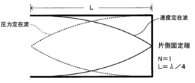
- resonance is formed most efficiently when the length L coincides with an even multiple of a quarter of the wavelength ⁇ . That is, it is expressed by the following formula 2.
- L (N / 4) ⁇ (Expression 2) (However, N is an even number.)
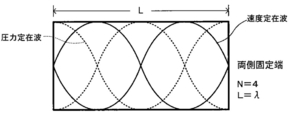
- the shape of the standing wave (resonance mode) is shown.
- a sparse / dense wave longitudinal wave
- the solid line is the velocity standing wave
- the dotted line is the pressure standing wave.
- the open end is an end at which the moving speed of the medium (liquid) in the longitudinal direction becomes zero, and conversely, the pressure becomes maximum.
- the closed end is defined as an end where the moving speed of the medium becomes zero.
- the closed end is considered as an acoustically hard wall and wave reflection occurs. If ideally completely closed or open, resonance standing waves of the form shown in FIGS. 13A to 13D and FIGS. 14A to 14C are generated by superposition of the waves. As a result, the standing wave pattern fluctuates, and the resonance frequency appears at a position deviated from the position obtained from the above equation 3. However, a stable ejection condition can be created by appropriately adjusting the driving frequency.
- the sound velocity c of the liquid is 1,200 [m / s]
- the length L of the liquid column resonance liquid chamber is 1.85 [mm]
- wall surfaces exist at both ends, and it is completely equivalent to the fixed ends on both sides.
- N 2 resonance mode
- the most efficient resonance frequency is derived from the above equation (2) as 324 kHz.
- the sound velocity c of the liquid is 1,200 [m / s]
- the length L of the liquid column resonance liquid chamber is 1.85 [mm]
- the liquid column resonance liquid chamber in the liquid column resonance droplet discharge means 11 shown in FIG. 11 is an end that can be described as an acoustically soft wall due to the influence of the opening of the discharge port, or both ends are equivalent to the closed end state. Although it is preferable to increase the frequency, it is not limited to this and may be an open end.
- the influence of the opening of the discharge port here means that the acoustic impedance is reduced, and in particular, the compliance component is increased. Therefore, the configuration in which the wall surfaces are formed at both ends in the longitudinal direction of the liquid column resonance liquid chamber as shown in FIG. 13B and FIG. 14A is the resonance mode of the both-side fixed end and all the resonance modes of the one-side open end that the discharge port side is regarded as opening. Is a preferable configuration.
- the numerical aperture of the discharge port, the opening arrangement position, and the cross-sectional shape of the discharge port are factors that determine the drive frequency, and the drive frequency can be appropriately determined according to this.
- the restriction at the tip of the liquid column resonance liquid chamber, which has been the fixed end gradually loosens, a resonance standing wave that is substantially close to the open end is generated, and the drive frequency increases.
- the opening position of the discharge port that is closest to the liquid supply channel is a starting point, and the loose restriction condition is applied.
- the cross-sectional shape of the discharge port is round or the volume of the discharge port varies depending on the frame thickness.
- the upper standing wave has a short wavelength and is higher than the driving frequency.
- the vibration generating means When a voltage is applied to the vibration generating means at the drive frequency determined in this way, the vibration generating means is deformed, and a resonant standing wave is generated most efficiently at the drive frequency. Further, the liquid column resonance standing wave is generated even at a frequency in the vicinity of the drive frequency at which the resonance standing wave is generated most efficiently. That is, when the length between both ends in the longitudinal direction of the liquid column resonance liquid chamber is L, and the distance to the discharge port closest to the end on the liquid supply side is Le, both the lengths of L and Le are used. It is possible to oscillate the vibration generating means using a drive waveform whose main component is the drive frequency f in the range determined by the following formulas 4 and 5 to induce liquid column resonance and eject liquid droplets from the ejection port. It is.
- the ratio of the length L between both ends in the longitudinal direction of the liquid column resonance liquid chamber to the distance Le to the discharge port closest to the end on the liquid supply side is preferably Le / L> 0.6.
- a liquid column resonance pressure standing wave is formed in the liquid column resonance liquid chamber 18 of FIG. 11 using the principle of the liquid column resonance phenomenon described above, and the discharge port 19 disposed in a part of the liquid column resonance liquid chamber 18. In this case, droplet discharge occurs continuously. Note that it is preferable to dispose the discharge port 19 at a position where the standing wave pressure fluctuates the most, because the discharge efficiency becomes high and the device can be driven at a low voltage. Further, although one discharge column 19 may be provided for one liquid column resonance liquid chamber 18, it is preferable to arrange a plurality of discharge ports 19 from the viewpoint of productivity. Specifically, it is preferably between 2 and 100.
- the pitch between discharge ports is 20 [micrometers] or more and below the length of a liquid column resonance liquid chamber.
- the state of the liquid column resonance phenomenon occurring in the liquid column resonance liquid chamber in the droplet discharge head in the droplet forming unit will be described with reference to FIGS. 15A to 15E showing the state.
- the solid line drawn in the liquid column resonance liquid chamber represents the velocity distribution plotting the velocity at any measurement position from the fixed end side to the liquid common supply path side end in the liquid column resonance liquid chamber.
- the direction from the liquid common supply path side to the liquid column resonance liquid chamber is +, and the opposite direction is-.
- the dotted line marked in the liquid column resonance liquid chamber indicates a pressure distribution in which the pressure value at each arbitrary measurement position between the fixed end side and the liquid common supply path side end in the liquid column resonance liquid chamber is plotted.
- FIG. 15A shows a pressure waveform and a velocity waveform in the liquid column resonance liquid chamber 18 when droplets are discharged.
- FIG. 15B the meniscus pressure increases again after the liquid is drawn immediately after the droplet is discharged.
- the pressure in the flow path provided with the discharge port 19 in the liquid column resonance liquid chamber 18 is maximum.
- FIG. 15C the positive pressure in the vicinity of the discharge port 19 decreases, and the liquid droplet 21 is discharged in a negative pressure direction.
- the pressure of the discharge port 19 vicinity becomes minimum. From this time, filling of the liquid component resonance liquid chamber 18 with the toner component liquid 14 starts. Thereafter, as shown in FIG. 15E, the negative pressure in the vicinity of the discharge port 19 decreases, and shifts to the positive pressure direction. At this time, the filling of the toner component liquid 14 is completed. Then, as shown in FIG. 15A again, the positive pressure in the droplet discharge region of the liquid column resonance liquid chamber 18 becomes maximum, and the droplet 21 is discharged from the discharge port 19.
- a standing wave due to liquid column resonance is generated in the liquid column resonance liquid chamber by high-frequency driving of the vibration generating means, and corresponds to an antinode of standing wave due to liquid column resonance where the pressure changes most. Since the discharge port 19 is arranged in the droplet discharge region to be discharged, the droplet 21 is continuously discharged from the discharge port 19 according to the antinode period.
- the toner of the present invention can be obtained by solidifying and then collecting the droplets of the toner component liquid discharged into the gas from the droplet discharge means described above.
- Droplet solidification means In order to solidify the liquid droplets, the concept varies depending on the properties of the toner component liquid, but basically any means can be used as long as the toner component liquid can be brought into a solid state. For example, if the toner component liquid is obtained by dissolving or dispersing a solid raw material in a volatile solvent, it can be achieved by drying the droplets in the conveying airflow after droplet ejection, that is, volatilizing the solvent. . In drying the solvent, the drying state can be adjusted by appropriately selecting the temperature, vapor pressure, gas type, and the like of the gas to be injected.
- the particles may be additionally dried in a separate step after the collection as long as the collected particles maintain a solid state. Even if it does not follow the said example, you may achieve by application of a temperature change, a chemical reaction, etc.
- Solid particle collecting means The solidified particles can be recovered from the air by a known powder collecting means such as a cyclone collecting or a back filter.
- FIG. 16 is a cross-sectional view of an example of a toner manufacturing apparatus for carrying out the toner manufacturing method of the present invention.
- the toner manufacturing apparatus 1 mainly includes a droplet discharge means 2 and a dry collection unit 60.
- the droplet discharge means 2 supplies a raw material container 13 for storing the toner component liquid 14 and the toner component liquid 14 stored in the raw material container 13 to the droplet discharge means 2 through the liquid supply pipe 16.
- a liquid circulation pump 15 that pumps the toner component liquid 14 in the liquid supply pipe 16 to return to the raw material container 13 through the liquid return pipe 22 is connected to the liquid droplet discharge means 2 as needed.
- the liquid supply pipe 16 is provided with a liquid pressure gauge P1
- the dry collection unit 60 is provided with an in-chamber pressure gauge P2.
- the pressure of liquid feeding to the droplet discharge means 2 and the pressure in the dry collection unit 60 are as follows. It is managed by pressure gauges P1 and P2. At this time, if the relationship of P1> P2, the toner component liquid 14 may ooze out from the discharge port 19, and if P1 ⁇ P2, gas may enter the discharge means and the discharge may stop. , P1 ⁇ P2.
- a transport airflow 1001 created from the transport airflow inlet 64 is formed in the chamber 61.
- the droplets 21 discharged from the droplet discharge means 2 are transported downward not only by gravity but also by a transport airflow 1001 and collected by the solidified particle collecting means 62.
- symbol 65 is a conveyance airflow discharge port
- symbol 63 is a solidified particle storage part.
- coalescence When the ejected droplets come into contact with each other before drying, the droplets coalesce into one particle (hereinafter this phenomenon is called coalescence).
- this phenomenon is called coalescence.
- the ejected droplets have a constant initial velocity, but eventually become stalled due to air resistance.
- the jetted droplets catch up with the stalled particles and coalesce as a result. Since this phenomenon occurs constantly, the particle size distribution is greatly deteriorated when the particles are collected.
- a part of the carrier airflow 1001 is arranged in the same direction as the liquid droplet ejection direction by the airflow passage 12 in the vicinity of the liquid droplet ejection means as a first airflow. It is possible to prevent a drop in the droplet speed immediately after the droplet is discharged and to prevent coalescence.
- the direction may be transverse to the ejection direction. Alternatively, although not shown, it may have an angle, and it is desirable to have such an angle that the droplets are separated from the droplet discharge means.
- the anti-adhesion airflow is applied from the lateral direction to the droplet discharge, it is desirable that the trajectories do not overlap when the droplets are conveyed by the anti-adhesion airflow from the discharge port. .
- the solidified particles may be conveyed to the solidified particle collecting means 62 by the second air stream.
- ⁇ It is desirable that the speed of the first air stream is equal to or higher than the droplet jet speed. If the speed of the anti-adhesion airflow is lower than the droplet ejection speed, it is difficult to exert the function of preventing the droplet particles, which is the original purpose of the anti-adhesion airflow, from contacting.
- the properties of the first air stream can be added with conditions so that the droplets do not coalesce with each other, and may not necessarily be the same as the second air stream. Further, a chemical substance that promotes solidification of the particle surface may be mixed in the anti-adhesion airflow, or may be imparted in anticipation of physical action.
- the carrier airflow 1001 is not particularly limited as a state of airflow, and may be a laminar flow, a swirl flow, or a turbulent flow. There is no particular limitation on the type of gas constituting the carrier airflow 1001, and air or a non-combustible gas such as nitrogen may be used. Further, the temperature of the conveying airflow 1001 can be adjusted as appropriate, and it is desirable that there is no fluctuation during production. Further, a means for changing the airflow state of the carrier airflow 1001 in the chamber 61 may be taken. The carrier airflow 1001 may be used not only to prevent the adhesion of the droplets 21 but also to prevent the droplets 21 from adhering to the chamber 61.
- the conveying airflow is preferably 2.0 m / s to 8.0 m / s, and more preferably 6.0 m / s to 8.0 m / s. If the conveying air flow is smaller than 2.0 m / s, the third and subsequent peaks may occur in the volume-based particle size distribution of the toner, and if it is larger than 8.0 m / s, the second volume in the volume-based particle size distribution of the toner. The peak may disappear, and the cleaning performance may deteriorate.
- a toner having a second peak particle diameter in a region where the volume-based particle size distribution is 1.21 to 1.31 times the mode diameter can be produced.
- secondary drying is performed as necessary to reduce this.
- general known drying means such as fluidized bed drying or vacuum drying can be used. If the organic solvent remains in the toner, not only the toner characteristics such as heat-resistant storage stability, fixability, and charging characteristics will change over time. Since the organic solvent volatilizes during fixing by heating, the possibility of adverse effects on the user and peripheral equipment is increased. Therefore, sufficient drying is performed.
- Specific means for externally adding a silicone oil-treated external additive and other external additives to the obtained toner powder after drying include a method of applying an impact force to the mixture by a high-speed rotating blade, and a mixture in a high-speed air stream. There is a method in which particles are injected and accelerated so that particles or composite particles collide with an appropriate collision plate.
- Examples of equipment used include, for example, an on-mill (made by Hosokawa Micron Corporation), an I-type mill (made by Nippon Pneumatic Co., Ltd.), and a pulverization air pressure reduced, a hybridization system (made by Nara Machinery Co., Ltd.) ), Kryptron system (manufactured by Kawasaki Heavy Industries, Ltd.), automatic mortar and the like.
- the image forming apparatus of the present invention forms an image using the toner of the present invention.
- the toner of the present invention can be used as either a one-component developer or a two-component developer, but is preferably used as a one-component developer.
- the image forming apparatus of the present invention preferably has an endless intermediate transfer unit.
- the image forming apparatus of the present invention preferably includes a latent image carrier and a cleaning unit that cleans the toner remaining on the latent image carrier and / or the intermediate transfer unit. At this time, the cleaning means may or may not have a cleaning blade.
- the image forming apparatus preferably includes a primary transfer unit, a toner removing unit, a secondary transfer unit, and an intermediate transfer body toner removing unit.
- the primary transfer means is means for transferring a visible image formed by toner on the surface of the latent image carrier to an intermediate transfer body.
- the toner removing means is means for removing the residual toner on the surface of the latent image carrier with a latent image carrier cleaning blade after the transfer.
- the secondary transfer unit is a unit that transfers the visible image from the intermediate transfer member to a transfer target.
- the intermediate transfer body toner removing means is means for removing the residual toner on the intermediate transfer body with an intermediate transfer body cleaning blade after the transfer.
- the rebound resilience of the latent image carrier cleaning blade is preferably 10% to 35%.
- the latent image carrier cleaning blade is preferably in contact with the latent image carrier at a pressure of 20 N / m to 50 N / m.
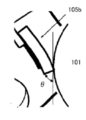
- the contact angle ⁇ formed by the end surface of the latent image carrier cleaning blade and the tangent line from the contact point between the latent image carrier surface is preferably 70 ° to 82 °.
- the rebound resilience of the intermediate transfer member cleaning blade is preferably 35% to 55%.
- the intermediate transfer member cleaning blade is preferably in contact with the intermediate transfer member at a pressure of 20 N / m to 50 N / m.
- the contact angle ⁇ formed by the tangent line from the contact point between the end surface of the intermediate transfer member cleaning blade and the surface of the intermediate transfer member is preferably 70 to 82 °.
- the image forming apparatus of the present invention preferably includes a fixing unit that fixes an image using a roller having a heating device or a belt having a heating device. Furthermore, the image forming apparatus of the present invention preferably has a fixing unit that does not require oil application to the fixing member. Further, the image forming apparatus preferably includes other means appropriately selected as necessary, for example, a static elimination means, a recycling means, a control means, and the like.
- the latent image carrier, the developing unit, the cleaning unit, and other components may be configured as a process cartridge, and the process cartridge may be configured to be detachable from the image forming apparatus main body. Further, at least one of charging means, exposure means, developing means, transfer means, separation means, and cleaning means is supported together with the latent image carrier to form a process cartridge, which is a detachable single unit to the image forming apparatus main body.
- the image forming apparatus main body may be configured to be detachable using guide means such as rails.
- FIG. 3 shows an example of the image forming apparatus of the present invention.
- a latent image carrier 101 that is driven to rotate clockwise in FIG. 3 is housed in a main body housing (not shown).
- a charging device is provided around the latent image carrier 101. 102, an exposure device 103, a developing device 104 having the toner (T) of the present invention, a cleaning unit 105, an intermediate transfer member 106, a support roller 107, a transfer roller 108, a discharging means (not shown).
- the image forming apparatus includes a paper feed cassette (not shown) that stores a plurality of recording papers (P) as an example of a recording medium, and the recording paper (P) in the paper feed cassette is a paper feed (not shown). After the timing is adjusted by a pair of registration rollers (not shown) one by one by the rollers, the rollers are sent out between a transfer roller 108 as a transfer unit and the intermediate transfer member 106.
- the latent image carrier 101 is driven to rotate clockwise in FIG. 3 so that the latent image carrier 101 is uniformly charged by the charging device 102 and then modulated by the exposure device 103 with the image data. Then, an electrostatic latent image is formed on the latent image carrier 101 by irradiating the developed laser, and toner is attached to the latent image carrier 101 on which the electrostatic latent image is formed by the developing device 104 and developed. Next, a transfer bias is applied from the latent image carrier 101 on which the toner image is formed by the developing device 104 to the intermediate transfer member 106 to transfer the toner image onto the intermediate transfer member 106, and the intermediate transfer member 106 and the transfer roller are further transferred. By conveying the recording paper (P) between 108, the toner image is transferred to the recording paper (P). Further, the recording paper (P) on which the toner image is transferred is conveyed to a fixing means (not shown).
- the fixing unit includes a fixing roller that is heated to a predetermined fixing temperature by a built-in heater and a pressure roller that is pressed against the fixing roller with a predetermined pressure, and heats and presses the recording paper conveyed from the transfer roller 108. After fixing the toner image on the recording paper to the recording paper, the toner image is discharged onto a paper discharge tray (not shown).
- the image forming apparatus further rotates the latent image carrier 101 on which the toner image is transferred to the recording paper by the transfer roller 108, and scrapes and removes the toner remaining on the surface of the latent image carrier 101 by the cleaning unit 105. After that, the charge is removed by a charge removal device (not shown).
- the image forming apparatus uniformly charges the latent image carrier 101 neutralized by the static eliminator with the charging device 102, and then performs the next image formation in the same manner as described above.
- Latent image carrier 101 The material, shape, structure, size and the like of the latent image carrier 101 are not particularly limited and can be appropriately selected from known ones.
- the shape is preferably a drum shape or a belt shape.
- the material include inorganic latent image carriers such as amorphous silicon and selenium, and organic latent image carriers such as polysilane and phthalopolymethine. Among these, amorphous silicon and an organic latent image carrier are preferable from the viewpoint of long life.
- the electrostatic latent image can be formed on the latent image carrier 101 by, for example, charging the surface of the latent image carrier 101 and then exposing it like an image. Can be performed.
- Electrostatic latent image forming means includes at least a charging device 102 that charges the surface of the latent image carrier 101 and an exposure device 103 that exposes the surface of the latent image carrier 101 imagewise.
- the charging can be performed, for example, by applying a voltage to the surface of the latent image carrier 101 using the charging device 102.
- the charging device 102 is not particularly limited and may be appropriately selected according to the purpose.
- the charging device 102 includes a conductive or semiconductive roller, a brush, a film, a rubber blade, and the like, which is a publicly known contact.
- Non-contact chargers using corona discharge such as chargers, corotrons, scorotrons and the like can be mentioned.
- the shape of the charging device 102 may be in the form of a magnetic brush, a fur brush, or the like in addition to the roller, and can be selected according to the specifications and form of the electrophotographic apparatus.
- the magnetic brush is composed of, for example, various ferrite particles such as Zn—Cu ferrite as a charging member, a non-magnetic conductive sleeve for supporting it, and a magnet roll included in the non-magnetic conductive sleeve.
- a brush for example, as a material of the fur brush, a fur treated with carbon, copper sulfide, metal or metal oxide is used, and this is wound around a metal or other conductive core. It is configured by pasting.
- the charging device 102 is not limited to the contact type charger as described above. However, since an image forming apparatus in which ozone generated from the charger is reduced is obtained, a contact type charger is used. preferable.
- the exposure can be performed, for example, by exposing the surface of the latent image carrier imagewise using the exposure apparatus 103.
- the exposure device 103 is not particularly limited as long as it can expose the surface of the latent image carrier 101 charged by the charging device 102 like an image to be formed, and may be appropriately selected according to the purpose. Examples thereof include various exposure devices such as a copying optical system, a rod lens array system, a laser optical system, and a liquid crystal shutter optical system.
- the development can be performed, for example, by developing the electrostatic latent image using the toner of the present invention, and can be performed by the developing device 104.
- the developing device 104 as the developing unit is not particularly limited as long as it can be developed using, for example, the toner of the present invention, and can be appropriately selected from known ones.
- the toner of the present invention can be selected.
- a preferable example is one that contains at least a developing device that can accommodate and apply the toner to the electrostatic latent image in a contact or non-contact manner.
- the developing device 104 carries toner on its peripheral surface, rotates in contact with the latent image carrier 101, and develops the toner by supplying toner to the electrostatic latent image formed on the latent image carrier 101.
- An embodiment having a roller 140 and a thin layer forming member 141 that contacts the peripheral surface of the developing roller 140 and thins the toner on the developing roller 140 is preferable.
- the developing roller 140 either a metal roller or an elastic roller is preferably used.
- a metal roller there is no restriction
- the metal roller can be blasted to produce the developing roller 140 having an arbitrary surface friction coefficient relatively easily. Specifically, by treating the aluminum roller with glass bead blasting, the roller surface can be roughened, and an appropriate toner adhesion amount can be obtained on the developing roller.
- the elastic roller a roller coated with an elastic rubber layer is used, and a surface coat layer made of a material that is easily charged to a polarity opposite to that of the toner is provided on the surface.
- the elastic rubber layer is set to a hardness of 60 degrees or less according to JIS-A in order to prevent toner deterioration due to pressure concentration at the contact portion with the thin layer forming member 141.
- the surface roughness (Ra) of the elastic roller is set to 0.3 ⁇ m to 2.0 ⁇ m, and a necessary amount of toner is held on the surface.
- the elastic rubber layer is set to a resistance value of 10 3 ⁇ to 10 10 ⁇ . .
- the developing roller 140 rotates in the clockwise direction, and conveys the toner held on the surface to a position facing the thin layer forming member 141 and the latent image carrier 101.
- the thin layer forming member 141 is provided at a position lower than the contact position between the supply roller 142 and the developing roller 140.
- the thin layer forming member 141 is made of a metal leaf spring material such as stainless steel (SUS) or phosphor bronze, and the free end is brought into contact with the surface of the developing roller 140 with a pressing force of 10 N / m to 40 N / m. Then, the toner that has passed under the pressure is thinned and a charge is applied by triboelectric charging. Further, a regulation bias having a value offset in the same direction as the charging polarity of the toner with respect to the developing bias is applied to the thin layer forming member 141 in order to assist frictional charging.
- the rubber elastic body constituting the surface of the developing roller 140 is not particularly limited and may be appropriately selected depending on the intended purpose. Examples thereof include styrene-butadiene copolymer rubber and acrylonitrile-butadiene copolymer rubber. Acrylic rubber, epichlorohydrin rubber, urethane rubber, silicone rubber, or a blend of two or more thereof. Among these, a blend rubber of epichlorohydrin rubber and acrylonitrile-butadiene copolymer rubber is particularly preferable.
- the developing roller 140 is manufactured, for example, by covering the outer periphery of the conductive shaft with a rubber elastic body.
- the conductive shaft is made of a metal such as stainless steel (SUS), for example.
- the transfer can be performed, for example, by charging the latent image carrier 101 and can be performed by a transfer roller.
- the transfer roller includes a primary transfer unit that transfers a toner image onto the intermediate transfer member 106 to form a transfer image, and a secondary transfer unit that transfers the transfer image onto a recording paper (P) (transfer roller). 108) is preferred.
- P recording paper
- two or more colors, preferably full color toners are used as the toner, and a primary transfer means for transferring the toner image onto the intermediate transfer member 106 to form a composite transfer image, and the composite transfer image on the recording paper ( An embodiment having secondary transfer means for transferring onto P) is more preferred.
- the intermediate transfer member 106 is not particularly limited, and can be appropriately selected from known transfer members according to the purpose. For example, a transfer belt and the like are preferable.
- the intermediate transfer member cleaning blade 120 preferably applies a pressing force of 20 N / m to 50 N / m to the intermediate transfer member. At that time, the contact portion between the intermediate transfer member cleaning blade 120 and the surface of the intermediate transfer member 106 is enlarged, and the intermediate transfer member cleaning blade on the surface of the intermediate transfer member 106 is prevented from dispersing the external additive and the toner passage blocking force.
- the contact angle formed by the tangent at the contact point with 120 and the surface of the intermediate transfer member cleaning blade 20 on the intermediate transfer member 6 side is set to 70 ° to 82 °.
- the contact angle formed between the tangent line at the contact point with the intermediate transfer member cleaning blade 120 and the surface of the intermediate transfer member cleaning blade 120 on the intermediate transfer member 106 side is set to 70 ° to 82 °. It is possible to obtain a toner distribution blocking force with a sharp distribution from the applied pressing force.
- the rebound resilience of the intermediate transfer member cleaning blade in the range of 35% to 55%, it is possible to cope with the uneven frictional force generated in the longitudinal direction of the blade by elastic deformation and maintain stable contact. It is possible.
- both the latent image carrier cleaning blade and the intermediate transfer member cleaning blade have low rebound resilience, a low contact pressure, and a large contact angle
- the latent image carrier cleaning blade and the intermediate transfer member cleaning blade in an L / L environment Since the rebound resilience is low, the contact pressure is low, and the contact angle is large, the blocking force of the external additive and toner is the worst condition.
- both the latent image carrier cleaning blade and the intermediate transfer member cleaning blade have high rebound resilience, a high contact pressure, and a small contact angle
- the latent image carrier cleaning blade and the intermediate transfer member cleaning blade in an H / H environment Since the rebound resilience of the blade is high, the contact pressure is high, and the contact angle is small, the blades are in the worst condition.
- the transfer means (primary transfer means, secondary transfer means) preferably has at least a transfer device that peels and charges the toner image formed on the latent image carrier 101 toward the recording paper (P).
- Examples of the transfer means include a corona transfer device using corona discharge, a transfer belt, a transfer roller, a pressure transfer roller, and an adhesive transfer device.
- the recording paper (P) is typically plain paper, but is not particularly limited as long as it can transfer an unfixed image after development, and can be appropriately selected according to the purpose.
- a PET base for OHP can also be used.
- the fixing can be performed on the toner image transferred to the recording paper (P) by using a fixing unit, and is performed each time the toner image of each color is transferred to the recording paper (P). Alternatively, it may be performed at the same time in a state where toner images of respective colors are laminated.
- the fixing unit is not particularly limited and may be appropriately selected depending on the intended purpose, but a known heating and pressing unit is preferable. Examples of the heating and pressing unit include a combination of a heating roller and a pressure roller, and a combination of a heating roller, a pressure roller, and an endless belt.
- the heating temperature by the heating and pressing means is preferably 80 ° C. to 200 ° C.
- the fixing device may be a soft roller type fixing device having a fluorine-based surface layer composition as shown in FIG.
- the heating roller 109 has an elastic layer 111 made of silicone rubber and a PFA (tetrafluoroethylene-perfluoroalkyl vinyl ether copolymer) surface layer 112 on an aluminum core 110, and a heater 113 inside the aluminum core. It has.
- the pressure roller 114 has an elastic body layer 116 made of silicone rubber and a PFA surface layer 117 on an aluminum core metal 115.
- the recording paper P on which the unfixed image 118 is printed is passed as shown in the figure.
- a known optical fixing device may be used, for example, together with or instead of the fixing means depending on the purpose.
- the neutralization can be performed, for example, by applying a neutralization bias to the latent image carrier, and can be suitably performed by a neutralization unit.
- the neutralization means is not particularly limited, and may be appropriately selected from known neutralizers as long as it can apply a neutralization bias to the latent image carrier.
- a neutralization lamp is preferably used. Can be mentioned.
- Cleaning can be suitably performed, for example, by removing toner remaining on the latent image carrier by a cleaning unit.
- the cleaning means is not particularly limited and may be any one selected from known cleaners as long as it can remove toner remaining on the latent image carrier.
- a magnetic brush cleaner, an electrostatic brush cleaner, and the like Suitable examples include magnetic roller cleaners, blade cleaners, brush cleaners, web cleaners, and the like.
- blade cleaning is preferred as the least expensive means.
- FIG. 8 is a view showing the cleaning device 105 used in the image forming apparatus of the present invention
- FIG. 9 is a detailed explanatory view of the cleaning unit
- FIG. 10 is a detailed explanatory view of the cleaning blade.
- a cleaning unit 105 used for cleaning toner adhering to the surface of the latent image carrier 101 is supported by a toner recovery case 105c and a fulcrum shaft 105d provided in the toner recovery case 105c.
- a movable member 105e that can be rotated in the direction of the image carrier 101 and that can be mounted with a cleaning blade 105b and a fulcrum shaft 105d are mounted at the end of the movable member 105e opposite to the mounting position of the cleaning blade 105b.
- the latent image carrier cleaning blade 105b is composed of a plate-like cleaning blade 105b-1 shown in FIG. 10 and a support member 105b-2 for supporting the same. 105b is used by pressing the plate-like cleaning blade 105b-1 with a predetermined contact angle ⁇ on the surface of the latent image carrier 101 where the plate-like cleaning blade 105b-1 rotates in the direction of the arrow (clockwise) by a biasing means such as a spring.
- the material used for the plate-like cleaning blade 105b-1 is 60 to 80 in hardness [JIS-A type], 300 to 350% in elongation, 1.0 to 5.0% in permanent elongation, 300 A resin having a% modulus of 100 kg / cm 2 to 350 kg / cm 2 and a rebound resilience in the range of 10% to 35% is used, and a resin conventionally used in a plate blade member, such as urethane, styrene, It can be appropriately selected from thermoplastic resins such as olefin, vinyl chloride, polyester, polyamide, and fluorine resins. In particular, a lower cleaning blade friction coefficient is desirable.
- the material of the support member 105b-2 is not particularly limited.
- metal, plastic, ceramic, or the like can be used.
- a metal plate is preferable.
- a steel plate such as SUS. It is desirable to use an aluminum plate, a phosphor bronze plate, or the like.
- the frictional force increases at the contact portion between the cleaning blade 105b and the surface of the latent image carrier 101.
- the contact end of the cleaning blade 105b is caught in the rotation direction of the latent image carrier, resulting in destruction, or at least at the contact portion, the amplitude in the repetitive motion of the restoration from the compression to the elasticity is increased, and the surface of the latent image carrier As a result, the generation of a blocking layer is hindered, such as cleaning failure due to slipping of external additives and toner, and noise appears on the image. It is necessary to optimize the pressure and improve the external additive and toner stopping power.
- the elastic deformation around the contact portion of the cleaning blade 105b with the latent image carrier 101 increases, and the contact area tends to increase.
- the cleaning on the surface of the latent image carrier tends to increase. Since the contact angle formed between the tangent line at the contact point with the blade 105b and the surface on the latent image carrier 101 side of the cleaning blade 105b is 70 ° to 82 °, unnecessary contact is reduced and the applied pressure is reduced. It is possible to obtain a toner distribution blocking force with a sharp distribution from the pressure.
- the recycling can be suitably performed, for example, by transporting the toner removed by the cleaning unit to the developing unit by the recycling unit.
- Control can be suitably performed by controlling each means by a control means, for example.
- the control means is not particularly limited as long as it can control each means, and can be appropriately selected according to the purpose. Examples thereof include devices such as a sequencer and a computer.
- a good image can be obtained by using the electrostatic latent image developing toner that has excellent fixability and does not deteriorate due to stress in the developing process. Can be provided.
- FIG. 5 is a schematic view showing an example of a multicolor image forming apparatus to which the present invention is applied.
- FIG. 5 shows a tandem type full-color image forming apparatus.
- the image forming apparatus stores a latent image carrier 101 that is driven to rotate in the clockwise direction in the figure in a main body housing (not shown), and around the latent image carrier 101, a charging device 102, An exposure device 103, a developing device 104, an intermediate transfer member 106, a support roller 107, a transfer roller 108, and the like are arranged.
- the image forming apparatus includes a paper feeding cassette that stores a plurality of recording papers. The recording paper P in the paper feeding cassette is timed by a pair of registration rollers (not shown) one by one by a paper feeding roller (not shown). After the adjustment, the sheet is fed between the intermediate transfer member 106 and the transfer roller 108 and fixed by the fixing unit 119.
- the image forming apparatus rotates the latent image carrier 101 in the clockwise direction in FIG. 5, uniformly charges the latent image carrier 101 with the charging device 102, and then lasers modulated with image data by the exposure device 103.
- a developing device 104 attaches toner to the latent image carrier 101 on which the electrostatic latent image is formed and develops it.
- the image forming apparatus transfers the toner image formed by attaching the toner to the latent image carrier with the developing device 104 from the latent image carrier 101 to the intermediate transfer member. This is performed for each of the four colors of cyan (C), magenta (M), yellow (Y), and black (K) to form a full-color toner image.
- Reference numeral 120 denotes an intermediate transfer member cleaning blade.
- FIG. 6 is a schematic view showing an example of a revolver type full-color image forming apparatus.
- this image forming apparatus a plurality of colors of toner are sequentially developed on one latent image carrier 101 by switching the operation of the developing device. Then, the color toner image on the intermediate transfer member 106 is transferred to the recording paper P by the transfer roller 108, and the recording paper P to which the toner image has been transferred is conveyed to a fixing unit to obtain a fixed image.
- the image forming apparatus further rotates the latent image carrier 101 on which the toner image is transferred to the recording paper P by the intermediate transfer member 106, and scrapes the toner remaining on the surface of the latent image carrier 101 by the blade by the cleaning unit 105. After removing by dropping, the charge is removed by the charge removal unit.
- the image forming apparatus uniformly charges the latent image carrier 101 neutralized by the neutralization unit with the charging device 102, and then performs the next image formation as described above.
- the cleaning unit 105 is not limited to the one that scrapes the residual toner on the latent image carrier 101 with a blade, and may be one that scrapes the residual toner on the latent image carrier 101 with a fur brush, for example. .
- Reference numeral 120 denotes an intermediate transfer member cleaning blade.
- the process cartridge of the present invention can develop an electrostatic latent image carrier carrying an electrostatic latent image and the electrostatic latent image carried on the electrostatic latent image carrier using the toner of the present invention.
- a developing means for forming a visual image and further comprising other means such as a charging means, a developing means, a transfer means, a cleaning means, and a static elimination means, which are appropriately selected as necessary.
- the image forming apparatus main body is detachable.
- Examples of the developing means include at least a developer container that contains the toner or developer, and a developer carrier that carries and transports the toner or developer contained in the developer container. And a layer thickness regulating member for regulating the thickness of the toner layer to be carried.
- the process cartridge of the present invention can be detachably provided in various electrophotographic apparatuses, facsimiles, and printers, and is preferably detachably provided in the image forming apparatus of the present invention described later.
- the process cartridge includes a latent image carrier 101, and includes a charging device 102, a developing device 104, a transfer roller 108, and a cleaning unit 105, and other means as necessary.
- a charging device 102 for example, as shown in FIG. 7, the process cartridge includes a latent image carrier 101, and includes a charging device 102, a developing device 104, a transfer roller 108, and a cleaning unit 105, and other means as necessary.
- L shows exposure from the exposure apparatus
- P shows recording paper.
- the latent image carrier 101 the same one as the image forming apparatus can be used.
- An arbitrary charging member is used for the charging device 102.
- the latent image carrier 101 is rotated in the direction of the arrow while being charged by the charging device 102 and exposed (L) by the exposure means (not shown).
- An electrostatic latent image corresponding to the exposure image is formed on the surface.
- the electrostatic latent image is developed with toner by the developing device 104, and the toner development is transferred onto the recording paper (P) by the transfer roller 108 and printed out.
- the surface of the latent image carrier after the image transfer is cleaned by the cleaning unit 105 and further neutralized by a neutralizing unit (not shown), and the above operation is repeated again.
- Part represents “part by mass” unless otherwise specified.
- % Represents “% by mass” unless otherwise specified.
- the toner of the present invention is used as a one-component developer was evaluated.
- the toner of the present invention can be used as a two-component developer by using a suitable external addition treatment and a suitable carrier. Can also be used.
- the amount of free silicone oil was measured by a quantitative method comprising the following procedures (1) to (3).
- (2) Quantification of carbon content Quantification of carbon content in the sample from which free silicone oil was removed was measured with a CHN elemental analyzer (CHN coder MT-5 type (manufactured by Yanaco)).
- (3) Determination of free amount of silicone oil The free amount of silicone oil was determined by the following formula (1).
- Silicone oil release amount (C 0 -C 1 ) / C ⁇ 100 ⁇ 40/12 (mass%) (1) here, C: Carbon content (mass%) in the treatment agent silicone oil C 0 : Carbon content (mass%) in the sample before the extraction operation C 1 : carbon content in the sample after extraction operation (mass%) Coefficient 40/12: Conversion coefficient from the amount of C in the structure of polydimethylsiloxane (PDMS) to the total amount The structural formula of polydimethylsiloxane is shown below.
- a method for measuring the particle size distribution of the toner particles will be described.
- an apparatus for measuring the particle size distribution of toner particles by the Coulter Counter method there are Coulter Counter TA-II and Coulter Multisizer II (both manufactured by Coulter).
- the measuring method is as follows. First, 0.1 mL to 5 mL of a surfactant (preferably alkylbenzene sulfonate) was added as a dispersant to 100 mL to 150 mL of the electrolytic solution.
- the electrolytic solution was prepared by preparing approximately 1% NaCl aqueous solution using first grade sodium chloride, and ISOTON-II (manufactured by Coulter) was used.
- the measurement sample was further added in a solid content of 2 mg to 20 mg.
- the electrolytic solution in which the sample is suspended is subjected to dispersion treatment with an ultrasonic disperser for about 1 to 3 minutes, and the measurement apparatus (Coulter Multisizer II) is used to measure the volume of toner particles or toner using a 100 ⁇ m aperture as an aperture.
- the number was measured, and the volume distribution (volume reference particle size distribution) and the number distribution were calculated. From the obtained distribution, the volume average particle diameter (Dv) and the number average particle diameter (Dn) of the toner were determined.
- a channel it is 2.00 micrometers or more and less than 2.52 micrometers; 2.52 micrometers or more and less than 3.17 micrometers; 3.17 micrometers or more and less than 4.00 micrometers; 4.00 micrometers or more and less than 5.04 micrometers; 5.04 micrometers or more and less than 6.35 micrometers; .35 ⁇ m or more and less than 8.00 ⁇ m; 8.00 ⁇ m or more and less than 10.08 ⁇ m; 10.08 ⁇ m or more and less than 12.70 ⁇ m; 12.70 ⁇ m or more and less than 16.00 ⁇ m; 16.00 ⁇ m or more and less than 20.20 ⁇ m; Less than 40 ⁇ m; 25.40 ⁇ m or more and less than 32.00 ⁇ m; 13 channels of 32.00 ⁇ m or more and less than 40.30 ⁇ m were used, and particles having a particle size of 2.00 ⁇ m or more and less than 40.30 ⁇ m were targeted.
- an optical detection band method is suitable in which a suspension containing particles is passed through an imaging unit detection band on a flat plate, and a particle image is optically detected and analyzed by a CCD camera.
- the average circularity is a value obtained by dividing the perimeter of an equivalent circle having the same projected area obtained by this method by the perimeter of the actual particle. This value is a value measured as an average circularity by a flow type particle image analyzer FPIA-3000.
- 0.1 mL to 0.5 mL of a surfactant preferably alkylbenzene sulfonate
- a dispersant preferably alkylbenzene sulfonate
- 100 mL to 150 mL of water from which impure solids have been previously removed and further measurement is performed.
- About 0.1 to 0.5 g of sample was added.
- the suspension in which the sample is dispersed is subjected to a dispersion treatment with an ultrasonic disperser for about 1 to 3 minutes, and the concentration and dispersion of the toner is adjusted to 3,000 / 10,000 to 10,000 / ⁇ L by the above apparatus.
- a dispersion treatment with an ultrasonic disperser for about 1 to 3 minutes
- ⁇ Molecular weight >> The molecular weight of the polyester resin to be used was measured under the following conditions by normal GPC (gel permeation chromatography).
- ⁇ Device HLC-8220GPC (manufactured by Tosoh Corporation) Column: TSKgel SuperHZM-M x 3 ⁇ Temperature: 40 °C ⁇ Solvent: THF (tetrahydrofuran) ⁇ Flow rate: 0.35 mL / min ⁇ Sample: 0.01 mL injection of a sample with a concentration of 0.05% to 0.6% Molecular weight calibration prepared with a monodisperse polystyrene standard sample from the molecular weight distribution of the toner resin measured under the above conditions The weight average molecular weight Mw was calculated using the curve.
- ⁇ Glass transition point and endotherm For the measurement of the glass transition point of the polyester resin used, a differential scanning calorimeter (for example, DSC-60: manufactured by Shimadzu Corporation) was used. First, after heating from room temperature to 150 ° C. at a rate of temperature increase of 10 ° C./min, the sample was cooled to room temperature, and again heated to 150 ° C. at a rate of temperature increase of 10 ° C./min. The glass transition point was determined from the curve portion corresponding to 1/2 the height of the baseline above the glass transition point.
- DSC-60 manufactured by Shimadzu Corporation
- the endothermic amount and melting point of the release agent and crystalline resin were measured in the same manner.
- the endothermic amount was determined by calculating the peak area of the measured endothermic peak.
- the release agent used in the toner melts at a temperature lower than the fixing temperature of the toner, and the heat of fusion at that time appears as an endothermic peak.
- Some releasing agents are accompanied by a heat of transition due to a phase transition in the solid phase in addition to the heat of fusion.
- the total is defined as the endothermic amount of the heat of fusion.
- the BET specific surface area of the external additive was measured using a specific surface area meter auto soap 1 manufactured by QUANTACHROME as follows. About 0.1 g of a measurement sample was weighed in a cell and degassed for 12 hours or more at a temperature of 40 ° C. and a degree of vacuum of 1.0 ⁇ 10 ⁇ 3 mmHg or less. Thereafter, nitrogen gas was adsorbed in a state cooled with liquid nitrogen, and a value was obtained by a multipoint method.
- the particle diameter (primary average particle diameter) of the external additive used in the present invention is a particle size distribution measuring device using dynamic light scattering, DLS-700 manufactured by Otsuka Electronics Co., Ltd. or Coulter N4 manufactured by Coulter Electronics. Can be measured. However, since it is difficult to dissociate the secondary aggregation of the particles after the silicone oil treatment, it is preferable to directly obtain the particle diameter from a photograph obtained by a scanning electron microscope or a transmission electron microscope. In this case, at least 100 or more inorganic fine particles are observed and the average value of the major axis is obtained. In this example, measurement was performed with a scanning electron microscope S-4200 (manufactured by Hitachi, Ltd.).
- a metal tube having the same diameter as that of the latent image carrier and a width of 5 mm in the longitudinal direction is movable, a load cell is disposed on the back side of the movable surface, and a pressing force per length is measured to obtain a contact force.
- the length L between both ends in the longitudinal direction of the liquid column resonance liquid chamber 18 is 1.85 [mm]
- N 2 resonance mode
- positioned the discharge hole in the position of the antinode of the wave was used.
- the drive signal generation source was a NF company function generator WF 1973, which was connected to the vibration generation means with a polyethylene-coated lead wire.
- the driving frequency at this time is 340 [kHz] according to the liquid resonance frequency.
- the inner diameter of the chamber 61 is 400 mm, the height is 2,000 mm, and is fixed vertically, the upper end and the lower end are narrowed, the diameter of the carrier airflow inlet is 50 mm, and the diameter of the carrier airflow outlet is 50 mm.
- the droplet discharge means 2 is disposed at the center of the chamber 61 at a height of 300 mm from the upper end in the chamber 61.
- the carrier airflow was 8.0 m / s and 40 ° C. nitrogen.
- a carbon black dispersion as a colorant was prepared. 17 parts of carbon black (Rega L400; manufactured by Cabot) and 3 parts of pigment dispersant (Ajisper PB821, manufactured by Ajinomoto Fine Techno Co., Ltd.) were primarily dispersed in 80 parts of ethyl acetate using a mixer having stirring blades. . The obtained primary dispersion is finely dispersed by a strong shearing force using a bead mill (LMZ type manufactured by Ashizawa Finetech Co., Ltd., zirconia bead diameter 0.3 mm), and the secondary dispersion in which aggregates of 5 ⁇ m or more are completely removed. A liquid (colorant dispersion) was prepared.
- LMZ type manufactured by Ashizawa Finetech Co., Ltd., zirconia bead diameter 0.3 mm
- wax dispersion a wax dispersion was prepared.
- the obtained primary dispersion was heated to 80 ° C. with stirring to dissolve the carnauba wax, and then the liquid temperature was lowered to room temperature to precipitate wax particles so that the maximum diameter was 3 ⁇ m or less.
- the wax dispersant a polyethylene wax grafted with a styrene-butyl acrylate copolymer was used.
- the obtained dispersion is further finely dispersed by a strong shearing force using a bead mill (LMZ type manufactured by Ashizawa Finetech Co., Ltd., zirconia bead diameter 0.3 mm), and the maximum diameter is adjusted to 1 ⁇ m or less to disperse the wax.
- a liquid was obtained.
- a toner component liquid having the following composition to which a resin as a binder resin, the colorant dispersion, and the wax dispersion were added was prepared.
- 10 parts of amorphous polyester resin 1 (Mw: 20,000, acid value: 5 mg KOH / g, Tg: 55 ° C.) was dissolved in 90 parts of ethyl acetate using a mixer having stirring blades.
- 0.3 part of a cationic fluorosurfactant F150 manufactured by DIC
- the prepared toner pre-classifying base particles 1 are added with a water tank (0.5 parts of pure water of 100 parts of water and sodium dodecyl diphenyl ether disulfonate aqueous solution (“Eleminol MON-7”; manufactured by Sanyo Chemical Industries, Ltd.). And a toner particle dispersion was obtained. The obtained toner particle dispersion was stirred and then filtered, and the operation of redispersing the obtained cake in distilled water and filtering was repeated 10 times and classified. The cake obtained by filtering and separating the classified slurry was dried under reduced pressure at 40 ° C. for 24 hours to obtain toner base particles 1.
- toner base particles 7 were obtained in the same manner as in Production Example 2 except that the conveying air flow was set to 0.0 m / s.
- a toner particle 10 before toner classification was obtained in the same manner as in Production Example 1 except that the carrier air flow was 6.0 m / s in Production Example 1.
- the obtained toner pre-classifying base particles 10 were added with 0.5 parts of a water tank (sodium dodecyl diphenyl ether disulfonate aqueous solution (“Eleminol MON-7” manufactured by Sanyo Chemical Industries, Ltd.) to 100 parts of water).
- the toner particle dispersion was obtained.
- the obtained toner particle dispersion was stirred and then filtered, and the operation of redispersing the obtained cake in distilled water and filtering was repeated 14 times.
- the cake obtained by filtering and separating the classified slurry was dried under reduced pressure at 40 ° C. for 24 hours to obtain toner base particles 10.
- Example 1 Example 1 ⁇ External toner addition> 100 parts of toner base particles 1, 3 parts of silica 6 shown in Table 1, and 1 part of hydrophobic silica [HMDS (hexamethyldisilazane) -treated external additive] having a primary particle size of about 10 nm are added to a Henschel mixer. The developer of Example 1 was obtained.
- HMDS hexamethyldisilazane
- Examples 2 to 10, Comparative Examples 1 to 7 ⁇ External toner addition> Developers of Examples 2 to 10 and Comparative Examples 1 to 7 were obtained in the same manner as Example 1 except that the silicas shown in Table 1 were used in the types and addition amounts shown in Table 2.
- the obtained developer was subjected to the following evaluation.
- the toner remaining on the latent image carrier at the end of printing 2,000 sheets is peeled off with a tape (manufactured by Kihara Co., Ltd., T-tape), and L * is measured with a spectral densitometer Xrite 939 (manufactured by Xrite). And evaluated according to the following evaluation criteria.
- Latent image carrier cleaning property (2) >> Using a Ricoh Co., Ltd. IPSIO SP C220, a predetermined print pattern with a B / W ratio of 6% was printed continuously in a monochrome mode under an L / L environment (10 ° C., 15%). The impact resilience of the cleaning blade was 10%, the contact pressure was 20 N / m, and the contact angle was 82 °. This condition is that the repelling elasticity of the cleaning blade is low, the contact pressure is low, and the contact angle is large under the L / L environment, so that the external additive and toner blocking force is the worst.
- Latent image carrier cleaning property (3) By using IPSIO SP C220 manufactured by Ricoh Co., Ltd., a predetermined print pattern having a B / W ratio of 6% was continuously printed in a monochrome mode in an H / H environment (27 ° C., 80%). The impact resilience of the cleaning blade was 35%, the contact pressure was 50 N / m, and the contact angle was 70 °. This condition is a condition in which the cleaning blade has a high rebound resilience, a high contact pressure, and a small contact angle in an H / H environment, so that the cleaning blade is broken and the turning up is worsened.
- Latent image carrier film scraping amount The film thickness of the latent image carrier was measured before and after evaluating the latent image carrier cleaning property (1), and the amount of film abrasion was measured. The film thickness at an arbitrary measuring point 80 is measured with an eddy current film thickness measuring instrument (Fischer), and the result is averaged to obtain the latent image carrier film scraping amount, which is evaluated according to the following evaluation criteria. did. ⁇ Evaluation criteria ⁇ ⁇ : 0.3 ⁇ m or less ⁇ : More than 0.3 ⁇ m, 0.4 ⁇ m or less ⁇ : More than 0.4 ⁇ m, 0.6 ⁇ m or less ⁇ : More than 0.6 ⁇ m
- the toner charge amount difference was measured before and after the evaluation of the latent image carrier cleaning property (1) to evaluate the degree of contamination of the regulating blade.
- the charge amount was obtained by averaging the toner on the developing roller with an average of 10 points using a suction type small charge amount measuring device manufactured by Trek Japan. Evaluation was made according to the following evaluation criteria.
- Image stability evaluation (1) Using a Ricoh Co., Ltd. IPSIO SP C220, a predetermined print pattern having a B / W ratio of 6% was printed continuously in a monochrome mode in an N / N environment (23 ° C., 45%) at 2,000 sheets. The impact resilience of the cleaning blade was 30%, the contact pressure was 30 N / m, and the contact angle was 75 °. Image quality (image density, fine line reproducibility, background stain) at the end of printing 2,000 sheets was evaluated according to the following evaluation criteria.
- Image stability evaluation (2) Using a Ricoh Co., Ltd. IPSIO SP C220, a predetermined print pattern having a B / W ratio of 6% was printed continuously in a monochrome mode in an N / N environment (23 ° C., 45%) at 2,000 sheets.
- the impact resilience of the cleaning blade was 30%, the contact pressure was 30 N / m, and the contact angle was 75 °.
- the image quality (image density, fine line reproducibility, background stain) at the end of printing 50,000 sheets was evaluated according to the following evaluation criteria.
- aspects of the present invention are as follows, for example.
- a toner containing a binder resin and a release agent The volume-based particle size distribution of the toner has a second peak particle size in a region 1.21 to 1.31 times the mode diameter; The toner has a particle size distribution (volume average particle diameter / number average particle diameter) of 1.08 to 1.15.
- ⁇ 3> The toner according to any one of ⁇ 1> to ⁇ 2>, wherein the average circularity is 0.98 to 1.00.
- ⁇ 4> The toner according to any one of ⁇ 1> to ⁇ 3>, containing an external additive treated with silicone oil.
- ⁇ 5> The toner according to ⁇ 4>, wherein the total silicone oil liberation amount is 0.20% by mass to 0.50% by mass with respect to the toner.
- ⁇ 6> The toner according to any one of ⁇ 4> to ⁇ 5>, wherein the external additive has a silicone oil content of 2 mg to 10 mg per 1 m 2 of a surface area of the external additive.
- Toner removing means for removing secondary transfer means for transferring the visible image from the intermediate transfer member to the transfer target, and after transfer, residual toner on the intermediate transfer member is removed by an intermediate transfer member cleaning blade.
- Intermediate transfer body toner removing means An image forming apparatus, wherein the toner is the toner according to any one of ⁇ 1> to ⁇ 6>.
- the rebound resilience of the latent image carrier cleaning blade is 10% to 35%, and the latent image carrier cleaning blade comes into contact with the latent image carrier at a pressure of 20 N / m to 50 N / m, and the latent image
- the rebound resilience of the intermediate transfer member cleaning blade is 35% to 55%, and the intermediate transfer member cleaning blade contacts the intermediate transfer member with a pressure of 20 N / m to 50 N / m, and the intermediate transfer member cleaning blade
- the image forming apparatus according to ⁇ 7>, wherein a contact angle ⁇ formed by a tangent line from a contact point between the end surface of the intermediate transfer member and the surface of the intermediate transfer member is 70 to 82 °.
- the process cartridge is configured to be detachable from the apparatus.
Landscapes
- Physics & Mathematics (AREA)
- General Physics & Mathematics (AREA)
- Chemical & Material Sciences (AREA)
- Inorganic Chemistry (AREA)
- Spectroscopy & Molecular Physics (AREA)
- Developing Agents For Electrophotography (AREA)
- Cleaning In Electrography (AREA)
- Electrostatic Charge, Transfer And Separation In Electrography (AREA)
Priority Applications (9)
| Application Number | Priority Date | Filing Date | Title |
|---|---|---|---|
| JP2015551537A JP6354765B2 (ja) | 2013-12-05 | 2014-12-03 | トナー、画像形成装置、及びプロセスカートリッジ |
| EP14867646.3A EP3079017B1 (en) | 2013-12-05 | 2014-12-03 | Toner, image formation device, and process cartridge |
| US15/035,786 US20160266521A1 (en) | 2013-12-05 | 2014-12-03 | Toner, image formation device, and process cartridge |
| RU2016126612A RU2644080C2 (ru) | 2013-12-05 | 2014-12-03 | Тонер, устройство формирования изображения и рабочий картридж |
| AU2014358256A AU2014358256B2 (en) | 2013-12-05 | 2014-12-03 | Toner, image formation device, and process cartridge |
| BR112016012452-9A BR112016012452B1 (pt) | 2013-12-05 | 2014-12-03 | Toner, dispositivo de formação de imagem e cartucho de processo |
| KR1020167018059A KR20160095097A (ko) | 2013-12-05 | 2014-12-03 | 토너, 화상 형성 장치 및 프로세스 카트리지 |
| CA2930107A CA2930107C (en) | 2013-12-05 | 2014-12-03 | Toner, image formation device, and process cartridge |
| CN201480066622.2A CN105814493B (zh) | 2013-12-05 | 2014-12-03 | 调色剂、成像装置和处理卡盒 |
Applications Claiming Priority (2)
| Application Number | Priority Date | Filing Date | Title |
|---|---|---|---|
| JP2013-252353 | 2013-12-05 | ||
| JP2013252353 | 2013-12-05 |
Publications (1)
| Publication Number | Publication Date |
|---|---|
| WO2015083735A1 true WO2015083735A1 (ja) | 2015-06-11 |
Family
ID=53273497
Family Applications (1)
| Application Number | Title | Priority Date | Filing Date |
|---|---|---|---|
| PCT/JP2014/081965 Ceased WO2015083735A1 (ja) | 2013-12-05 | 2014-12-03 | トナー、画像形成装置、及びプロセスカートリッジ |
Country Status (10)
| Country | Link |
|---|---|
| US (1) | US20160266521A1 (https=) |
| EP (1) | EP3079017B1 (https=) |
| JP (1) | JP6354765B2 (https=) |
| KR (1) | KR20160095097A (https=) |
| CN (1) | CN105814493B (https=) |
| AU (1) | AU2014358256B2 (https=) |
| BR (1) | BR112016012452B1 (https=) |
| CA (1) | CA2930107C (https=) |
| RU (1) | RU2644080C2 (https=) |
| WO (1) | WO2015083735A1 (https=) |
Families Citing this family (6)
| Publication number | Priority date | Publication date | Assignee | Title |
|---|---|---|---|---|
| JP5065781B2 (ja) * | 2007-07-10 | 2012-11-07 | 臼井国際産業株式会社 | 燃料噴射管用鋼管およびその製造方法 |
| CN106662826A (zh) * | 2014-08-06 | 2017-05-10 | 株式会社理光 | 调色剂 |
| JP6547897B2 (ja) | 2016-03-03 | 2019-07-24 | 株式会社リコー | トナー、トナー収容ユニット、及び画像形成装置 |
| JP6724575B2 (ja) * | 2016-06-10 | 2020-07-15 | 富士ゼロックス株式会社 | 画像形成装置及び画像形成方法 |
| CN108848283B (zh) | 2018-06-04 | 2019-09-06 | Oppo广东移动通信有限公司 | 扫描成像元件及相关产品和方法 |
| JP7275901B2 (ja) * | 2019-06-25 | 2023-05-18 | 株式会社リコー | 微粒子の製造装置及び微粒子の製造方法 |
Citations (9)
| Publication number | Priority date | Publication date | Assignee | Title |
|---|---|---|---|---|
| JP2002148847A (ja) | 2000-11-06 | 2002-05-22 | Ricoh Co Ltd | 電子写真用トナー外添剤、その製造方法、電子写真用トナー及び電子写真現像装置 |
| JP2007094358A (ja) * | 2005-09-02 | 2007-04-12 | Ricoh Co Ltd | 電子写真用トナーおよび画像形成装置 |
| JP2008292976A (ja) | 2007-03-20 | 2008-12-04 | Ricoh Co Ltd | トナーの製造方法、トナーの製造装置及びトナー |
| JP2009098194A (ja) | 2007-10-12 | 2009-05-07 | Fuji Xerox Co Ltd | 静電荷像現像用トナー、静電荷像現像剤、トナーカートリッジ、プロセスカートリッジ及び画像形成装置 |
| JP2010102195A (ja) | 2008-10-24 | 2010-05-06 | Ricoh Co Ltd | トナーの製造方法及び製造装置 |
| JP4647506B2 (ja) | 2006-01-27 | 2011-03-09 | 株式会社リコー | 粒子特にトナー粒子の製造方法、トナー粒子の製造装置及びトナー |
| JP2012198525A (ja) | 2011-03-09 | 2012-10-18 | Ricoh Co Ltd | トナー、画像形成装置及びプロセスカートリッジ |
| JP2012220809A (ja) * | 2011-04-12 | 2012-11-12 | Ricoh Co Ltd | トナーの製造方法 |
| JP2013033145A (ja) * | 2011-08-02 | 2013-02-14 | Ricoh Co Ltd | トナーの製造方法、トナーの製造装置及び樹脂微粒子の製造方法 |
Family Cites Families (6)
| Publication number | Priority date | Publication date | Assignee | Title |
|---|---|---|---|---|
| JP3058548B2 (ja) * | 1993-12-29 | 2000-07-04 | キヤノン株式会社 | 電子写真用現像剤 |
| JPH0895286A (ja) * | 1994-09-27 | 1996-04-12 | Matsushita Electric Ind Co Ltd | 電子写真用トナー |
| JP3888201B2 (ja) * | 2002-03-28 | 2007-02-28 | コニカミノルタホールディングス株式会社 | 静電潜像現像用トナーとその製造方法及び画像形成方法 |
| EP2031451B1 (en) * | 2006-06-08 | 2012-06-13 | Canon Kabushiki Kaisha | Toner |
| JP4966813B2 (ja) * | 2007-10-19 | 2012-07-04 | シャープ株式会社 | トナー、現像剤、現像装置および画像形成装置 |
| EP2554476B1 (en) * | 2011-08-04 | 2014-05-14 | AIRBUS HELICOPTERS DEUTSCHLAND GmbH | Lead lag damper for helicopter rotor unit |
-
2014
- 2014-12-03 WO PCT/JP2014/081965 patent/WO2015083735A1/ja not_active Ceased
- 2014-12-03 CA CA2930107A patent/CA2930107C/en active Active
- 2014-12-03 CN CN201480066622.2A patent/CN105814493B/zh not_active Expired - Fee Related
- 2014-12-03 BR BR112016012452-9A patent/BR112016012452B1/pt not_active IP Right Cessation
- 2014-12-03 AU AU2014358256A patent/AU2014358256B2/en active Active
- 2014-12-03 RU RU2016126612A patent/RU2644080C2/ru active
- 2014-12-03 EP EP14867646.3A patent/EP3079017B1/en not_active Not-in-force
- 2014-12-03 KR KR1020167018059A patent/KR20160095097A/ko not_active Ceased
- 2014-12-03 US US15/035,786 patent/US20160266521A1/en not_active Abandoned
- 2014-12-03 JP JP2015551537A patent/JP6354765B2/ja not_active Expired - Fee Related
Patent Citations (9)
| Publication number | Priority date | Publication date | Assignee | Title |
|---|---|---|---|---|
| JP2002148847A (ja) | 2000-11-06 | 2002-05-22 | Ricoh Co Ltd | 電子写真用トナー外添剤、その製造方法、電子写真用トナー及び電子写真現像装置 |
| JP2007094358A (ja) * | 2005-09-02 | 2007-04-12 | Ricoh Co Ltd | 電子写真用トナーおよび画像形成装置 |
| JP4647506B2 (ja) | 2006-01-27 | 2011-03-09 | 株式会社リコー | 粒子特にトナー粒子の製造方法、トナー粒子の製造装置及びトナー |
| JP2008292976A (ja) | 2007-03-20 | 2008-12-04 | Ricoh Co Ltd | トナーの製造方法、トナーの製造装置及びトナー |
| JP2009098194A (ja) | 2007-10-12 | 2009-05-07 | Fuji Xerox Co Ltd | 静電荷像現像用トナー、静電荷像現像剤、トナーカートリッジ、プロセスカートリッジ及び画像形成装置 |
| JP2010102195A (ja) | 2008-10-24 | 2010-05-06 | Ricoh Co Ltd | トナーの製造方法及び製造装置 |
| JP2012198525A (ja) | 2011-03-09 | 2012-10-18 | Ricoh Co Ltd | トナー、画像形成装置及びプロセスカートリッジ |
| JP2012220809A (ja) * | 2011-04-12 | 2012-11-12 | Ricoh Co Ltd | トナーの製造方法 |
| JP2013033145A (ja) * | 2011-08-02 | 2013-02-14 | Ricoh Co Ltd | トナーの製造方法、トナーの製造装置及び樹脂微粒子の製造方法 |
Non-Patent Citations (1)
| Title |
|---|
| See also references of EP3079017A4 |
Also Published As
| Publication number | Publication date |
|---|---|
| EP3079017A4 (en) | 2016-10-12 |
| CN105814493B (zh) | 2020-03-10 |
| KR20160095097A (ko) | 2016-08-10 |
| JP6354765B2 (ja) | 2018-07-11 |
| EP3079017B1 (en) | 2019-05-15 |
| EP3079017A1 (en) | 2016-10-12 |
| BR112016012452A2 (https=) | 2017-08-08 |
| CN105814493A (zh) | 2016-07-27 |
| US20160266521A1 (en) | 2016-09-15 |
| BR112016012452B1 (pt) | 2022-05-10 |
| CA2930107C (en) | 2018-07-24 |
| AU2014358256A1 (en) | 2016-05-26 |
| AU2014358256B2 (en) | 2017-02-02 |
| RU2644080C2 (ru) | 2018-02-07 |
| CA2930107A1 (en) | 2015-06-11 |
| JPWO2015083735A1 (ja) | 2017-03-16 |
Similar Documents
| Publication | Publication Date | Title |
|---|---|---|
| JP4755553B2 (ja) | 非磁性トナー、並びに画像形成方法、画像形成装置及びプロセスカートリッジ | |
| US8103199B2 (en) | Developing device, and image forming method and process cartridge using the developing device | |
| JP6079325B2 (ja) | トナー | |
| JP6354765B2 (ja) | トナー、画像形成装置、及びプロセスカートリッジ | |
| JP5754219B2 (ja) | トナーの製造方法 | |
| JP2014184429A (ja) | 粒子の製造方法、粒子製造装置及び静電荷像現像用トナー | |
| JP5239669B2 (ja) | トナー及びその製造方法、並びに現像剤、プロセスカートリッジ、画像形成方法、及び画像形成装置 | |
| JP6471460B2 (ja) | トナー及びトナー製造方法 | |
| JP5022046B2 (ja) | トナー及びその製造方法、並びに画像形成方法 | |
| JP5257676B2 (ja) | トナー及び現像剤、画像形成装置 | |
| JP5429609B2 (ja) | 静電荷像現像用トナー | |
| JP6350897B2 (ja) | トナーの製造方法 | |
| JP6642077B2 (ja) | 静電荷像現像用トナー、静電荷像現像剤、トナーカートリッジ、プロセスカートリッジ、画像形成装置、及び、画像形成方法 | |
| JP4566905B2 (ja) | トナーキット、並びに現像剤、プロセスカートリッジ、画像形成方法、及び画像形成装置 | |
| JP4960694B2 (ja) | トナーの製造方法、トナー、2成分現像剤、プロセスカートリッジ、及び画像形成装置 | |
| JP3191811B2 (ja) | 静電荷像現像用トナー | |
| JP6260090B2 (ja) | トナー、画像形成装置、及びトナーの製造方法 | |
| JP2015127739A (ja) | トナー、現像剤、画像形成装置及びプロセスカートリッジ | |
| JP4657913B2 (ja) | 粉砕トナー及びその製造方法、並びに現像剤、プロセスカートリッジ、画像形成方法、及び画像形成装置 | |
| JP2015108749A (ja) | トナー及びトナーの製造方法 | |
| JP4832265B2 (ja) | トナーの製造方法、トナー、2成分現像剤、プロセスカートリッジ、及び画像形成装置 | |
| JP5354366B2 (ja) | 現像装置及び画像形成装置 | |
| JP2014095814A (ja) | 画像定着方法、画像定着装置、画像形成方法、及び画像形成装置 |
Legal Events
| Date | Code | Title | Description |
|---|---|---|---|
| 121 | Ep: the epo has been informed by wipo that ep was designated in this application |
Ref document number: 14867646 Country of ref document: EP Kind code of ref document: A1 |
|
| ENP | Entry into the national phase |
Ref document number: 2015551537 Country of ref document: JP Kind code of ref document: A |
|
| ENP | Entry into the national phase |
Ref document number: 2930107 Country of ref document: CA |
|
| WWE | Wipo information: entry into national phase |
Ref document number: 15035786 Country of ref document: US |
|
| ENP | Entry into the national phase |
Ref document number: 2014358256 Country of ref document: AU Date of ref document: 20141203 Kind code of ref document: A |
|
| NENP | Non-entry into the national phase |
Ref country code: DE |
|
| REG | Reference to national code |
Ref country code: BR Ref legal event code: B01A Ref document number: 112016012452 Country of ref document: BR |
|
| REEP | Request for entry into the european phase |
Ref document number: 2014867646 Country of ref document: EP |
|
| WWE | Wipo information: entry into national phase |
Ref document number: 2014867646 Country of ref document: EP |
|
| ENP | Entry into the national phase |
Ref document number: 20167018059 Country of ref document: KR Kind code of ref document: A Ref document number: 2016126612 Country of ref document: RU Kind code of ref document: A |
|
| ENP | Entry into the national phase |
Ref document number: 112016012452 Country of ref document: BR Kind code of ref document: A2 Effective date: 20160531 |