WO2015083487A1 - 車両用電池搭載構造 - Google Patents
車両用電池搭載構造 Download PDFInfo
- Publication number
- WO2015083487A1 WO2015083487A1 PCT/JP2014/079496 JP2014079496W WO2015083487A1 WO 2015083487 A1 WO2015083487 A1 WO 2015083487A1 JP 2014079496 W JP2014079496 W JP 2014079496W WO 2015083487 A1 WO2015083487 A1 WO 2015083487A1
- Authority
- WO
- WIPO (PCT)
- Prior art keywords
- width direction
- vehicle width
- vehicle
- battery
- frame
- Prior art date
- Legal status (The legal status is an assumption and is not a legal conclusion. Google has not performed a legal analysis and makes no representation as to the accuracy of the status listed.)
- Ceased
Links
Images





Classifications
-
- B—PERFORMING OPERATIONS; TRANSPORTING
- B60—VEHICLES IN GENERAL
- B60K—ARRANGEMENT OR MOUNTING OF PROPULSION UNITS OR OF TRANSMISSIONS IN VEHICLES; ARRANGEMENT OR MOUNTING OF PLURAL DIVERSE PRIME-MOVERS IN VEHICLES; AUXILIARY DRIVES FOR VEHICLES; INSTRUMENTATION OR DASHBOARDS FOR VEHICLES; ARRANGEMENTS IN CONNECTION WITH COOLING, AIR INTAKE, GAS EXHAUST OR FUEL SUPPLY OF PROPULSION UNITS IN VEHICLES
- B60K1/00—Arrangement or mounting of electrical propulsion units
- B60K1/04—Arrangement or mounting of electrical propulsion units of the electric storage means for propulsion
-
- B—PERFORMING OPERATIONS; TRANSPORTING
- B62—LAND VEHICLES FOR TRAVELLING OTHERWISE THAN ON RAILS
- B62D—MOTOR VEHICLES; TRAILERS
- B62D21/00—Understructures, i.e. chassis frame on which a vehicle body may be mounted
- B62D21/15—Understructures, i.e. chassis frame on which a vehicle body may be mounted having impact absorbing means, e.g. a frame designed to permanently or temporarily change shape or dimension upon impact with another body
- B62D21/157—Understructures, i.e. chassis frame on which a vehicle body may be mounted having impact absorbing means, e.g. a frame designed to permanently or temporarily change shape or dimension upon impact with another body for side impacts
-
- B—PERFORMING OPERATIONS; TRANSPORTING
- B62—LAND VEHICLES FOR TRAVELLING OTHERWISE THAN ON RAILS
- B62D—MOTOR VEHICLES; TRAILERS
- B62D25/00—Superstructure or monocoque structure sub-units; Parts or details thereof not otherwise provided for
- B62D25/20—Floors or bottom sub-units
- B62D25/2009—Floors or bottom sub-units in connection with other superstructure subunits
- B62D25/2036—Floors or bottom sub-units in connection with other superstructure subunits the subunits being side panels, sills or pillars
-
- B—PERFORMING OPERATIONS; TRANSPORTING
- B60—VEHICLES IN GENERAL
- B60K—ARRANGEMENT OR MOUNTING OF PROPULSION UNITS OR OF TRANSMISSIONS IN VEHICLES; ARRANGEMENT OR MOUNTING OF PLURAL DIVERSE PRIME-MOVERS IN VEHICLES; AUXILIARY DRIVES FOR VEHICLES; INSTRUMENTATION OR DASHBOARDS FOR VEHICLES; ARRANGEMENTS IN CONNECTION WITH COOLING, AIR INTAKE, GAS EXHAUST OR FUEL SUPPLY OF PROPULSION UNITS IN VEHICLES
- B60K1/00—Arrangement or mounting of electrical propulsion units
- B60K1/04—Arrangement or mounting of electrical propulsion units of the electric storage means for propulsion
- B60K2001/0405—Arrangement or mounting of electrical propulsion units of the electric storage means for propulsion characterised by their position
- B60K2001/0438—Arrangement under the floor
-
- B—PERFORMING OPERATIONS; TRANSPORTING
- B60—VEHICLES IN GENERAL
- B60Y—INDEXING SCHEME RELATING TO ASPECTS CROSS-CUTTING VEHICLE TECHNOLOGY
- B60Y2306/00—Other features of vehicle sub-units
- B60Y2306/01—Reducing damages in case of crash, e.g. by improving battery protection
Definitions
- the present invention relates to a vehicle battery mounting structure.
- a battery frame that accommodates a driving battery disposed under the floor portion of an electric vehicle includes a resin battery tray and a metal frame-like frame provided on the outer wall side thereof. Is conventionally known (see, for example, JP-A-2011-124101).
- a collision load input by a side collision of the vehicle may cause a crack in the connection portion of the battery tray to the frame-shaped frame.
- a collision load input by a side collision of the vehicle may cause a crack in the connection portion of the battery tray to the frame-shaped frame.
- an object of the present invention is to obtain a vehicle battery mounting structure capable of suppressing the occurrence of cracks in a battery frame made of resin at the time of a side collision of the vehicle.
- the vehicle battery mounting structure is disposed on the vehicle width direction inner side of the energy absorbing member provided on the lower side of the floor panel and supports the battery.
- a resin-made battery frame lower that constitutes a battery frame together with a battery frame upper, a lower body portion joined to an outer end portion in the vehicle width direction of the battery frame lower, and a lower flange portion fixed to the lower surface side of the floor panel
- the inclined wall that inclines from the vehicle width direction outer side upper side toward the vehicle width direction inner side lower side at the vehicle width direction outer side end portion of the battery frame lower to which the lower main body portion is joined. Is formed. Therefore, the collision load input from the energy absorbing member to the battery frame lower at the time of a side collision of the vehicle is transmitted along the in-plane direction of the battery frame lower and the lower main body (inward in the vehicle width direction). That is, a bending moment in the out-of-plane direction is unlikely to occur with respect to the battery frame lower and the lower main body. Therefore, the occurrence of cracks in the battery frame lower (battery frame) is suppressed.
- the vehicle battery mounting structure of the second aspect is the vehicle battery mounting structure of the first aspect, wherein a part of the lower main body portion is from the vehicle width direction outer side to the vehicle width direction inner side.
- the upright portion is gradually separated from the inclined wall toward the front, and the inclined wall and the upright portion are filled and bonded with an adhesive.
- a part of lower main-body part is made into the standing part which leaves
- the vehicle battery mounting structure according to the third aspect of the present invention is the vehicle battery mounting structure according to the second aspect, and protrudes inward in the vehicle width direction from the vehicle width direction inner side end portion of the standing part.
- a plate member is provided on the upright portion.
- the plate member that protrudes inward in the vehicle width direction from the inner end portion in the vehicle width direction of the upright portion is provided in the upright portion. Therefore, even when the vehicle width direction inner side end portion of the upright portion is covered with the adhesive, the water droplet that has entered the upper surface of the upright portion flows down to the upper surface of the battery frame lower through the plate member. Therefore, the occurrence of galvanic corrosion at the standing part is suppressed.
- the vehicle battery mounting structure according to the fourth aspect of the present invention is the vehicle battery mounting structure according to any one of the first to third aspects, wherein the inclined wall has an outer end in the vehicle width direction. A vertical wall extending upward is formed.
- the vertical wall extending upward is formed at the outer end of the inclined wall in the vehicle width direction. Therefore, at the time of a side collision of the vehicle, the collision load is efficiently transmitted from the energy absorbing member to the battery frame lower and the lower main body (battery frame) through the vertical wall.
- a vehicle battery mounting structure is the vehicle battery mounting structure according to any one of the first to fourth aspects, and is provided at an outer end in the vehicle width direction of the battery frame upper.
- An upper ductile member having an upper main body portion to be joined and an upper flange portion fixed to the lower surface side of the floor panel together with the lower flange portion is provided, and the upper main body portion side of the upper flange portion has an outer side in the vehicle width direction.
- An inclined portion that is inclined from the upper side toward the lower side in the vehicle width direction is formed.
- the inclined portion is formed on the upper body portion side of the upper flange portion so as to incline from the upper side in the vehicle width direction toward the lower side in the vehicle width direction. Therefore, at the time of a side collision of the vehicle, the upper flange portion is easily bent and deformed with the boundary portion with the upper body portion as a fulcrum, and the stress load applied to the battery frame is reduced.
- the battery frame made of resin it is possible to prevent the battery frame made of resin from cracking at the time of a side collision of the vehicle.
- the second aspect of the present invention it is possible to further suppress or prevent the battery frame made of resin from cracking at the time of a side collision of the vehicle.
- galvanic corrosion can be prevented from occurring in the standing part.
- a collision load can be efficiently transmitted from the energy absorbing member to the battery frame at the time of a side collision of the vehicle.
- the fifth aspect of the present invention it is possible to reduce the stress load applied to the battery frame at the time of a vehicle side collision.
- an arrow UP appropriately shown in each drawing is an upward direction of the vehicle body
- an arrow FR is a forward direction of the vehicle body
- an arrow IN is an inner side of the vehicle width direction.
- the vertical direction of the vehicle body, the front / rear direction of the vehicle body direction, and the left / right direction of the vehicle body are indicated.
- each figure shows the left side of the vehicle body, the right side of the vehicle body is also symmetrical and identical, and therefore the description of the right side of the vehicle body will be omitted as appropriate.
- a pair of left and right undermembers (side frames) 14 extending in the longitudinal direction of the vehicle body and constituting a vehicle body skeleton structure are formed on the lower surface of a metal floor panel 12 constituting the floor portion of the vehicle body.
- the under member 14 is formed of a metal having a substantially hat-shaped cross section, and flange portions 15 projecting in the vehicle width direction are joined and fixed to the lower surfaces of the both ends of the floor panel 12 in the vehicle width direction by welding or the like. .
- the under member 14 is formed with a plurality of through-holes 14A through which a flange bolt 58 described later is inserted along the longitudinal direction (the longitudinal direction of the vehicle body).
- a weld nut 52 is provided on the upper surface of the under member 14 coaxially with each through hole 14A.
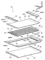
- a vehicle battery mounting structure 10 according to the present embodiment applied to a vehicle such as an electric vehicle is disposed on the vehicle body lower side of a floor panel 12 and supports a fuel cell stack 16 as a battery from the vehicle body lower side.
- (Stack frame) 20 is included.
- the battery frame 20 is made of a fiber reinforced resin (FRP), and is formed of a carbon fiber reinforced resin material (CFRP) as an example.
- the fuel cell stack 16 has an exterior portion 17 formed of a metal (or resin) in a rectangular box shape, and is stretched outward in the vehicle width direction at a plurality of predetermined positions in the peripheral edge of the lower end of the exterior portion 17.
- a leg portion 18 is formed integrally. Each leg 18 is formed with a through hole 18A for inserting a flange bolt 58 described later.
- the battery frame 20 includes an upper frame 22 as a battery frame upper, a lower frame 26 as a battery frame lower, and an intermediate provided between the upper frame 22 and the lower frame 26. And a core frame 30 as a member (reinforcing member).
- the upper frame 22 has a rectangular flat plate-like top plate 23 arranged along the horizontal direction, and both ends (outer end portions) in the vehicle width direction of the top plate 23 in the vehicle width direction so as to follow inclined walls 36 described later.
- a rectangular flat plate-like inclined wall 24 integrally connected obliquely upward toward the outer side, and both ends of the inclined wall 24 in the vehicle width direction are substantially directed outward in the vehicle width direction along an upper wall 37 described later.
- a rectangular flat-plate-shaped flange portion 25 that is integrally connected horizontally.
- the lower frame 26 has a rectangular flat plate-like bottom plate 27 arranged along the horizontal direction, and vehicle width direction both ends (outer end portions) of the bottom plate 27 toward the vehicle width direction outer side upper side (vehicle width direction outer side upper side). (Inward and downward in the vehicle width direction) to a rectangular flat plate-shaped inclined wall 28 integrally connected obliquely so as to be inclined at a predetermined angle, and to both ends (outer end portions) of the inclined wall 28 in the vehicle width direction. And a rectangular flat plate-like side wall portion 29 as a vertical wall integrally connected substantially vertically toward the vehicle body upper side.
- the height of the side wall portion 29 is such that when a lower ductility member 46 described later is joined to the lower frame 26, a boundary portion 49 between the side wall portion 47D and the lower flange portion 48 in the lower main body portion 47 of the lower ductility member 46. The height is almost reached (extending). In other words, the upper end surface of the side wall portion 29 is at a height position substantially the same as the upper end surface of the block portion 73 in the inner member 72 of the energy absorbing member 70 described later.
- the core frame 30 has a main body portion in which convex portions 33 having a substantially hat-shaped cross section extending along the vehicle width direction are formed in a plurality of rows (for example, five rows) arranged in the longitudinal direction of the vehicle body. 32 and projecting portions 34 formed so as to project continuously from the upper surface of the convex portion 33 to the vehicle body upper side at both ends in the vehicle width direction of the main body portion 32.
- An inner side in the vehicle width direction of the projecting portion 34 is an inclined wall 36 integrally and obliquely connected from the upper surface of the convex portion 33 toward the upper outer side in the vehicle width direction.
- a substantially horizontal upper wall 37 is integrally provided continuously outward in the width direction.
- the vehicle width direction outer side edge part of the protrusion part 34 is made into the end surface part 38 used as the cross section substantially perpendicular
- the protrusion 34 is formed in a substantially trapezoidal shape when viewed from the front-rear direction of the vehicle body (in front view).
- the battery frame 20 having a rectangular closed cross-sectional shape is generally configured.
- through holes 23 ⁇ / b> A and 33 ⁇ / b> A communicating with each other are formed at a plurality of predetermined positions on the top plate 23 of the upper frame 22 and the convex portion 33 of the core frame 30.
- a flange nut 54 is joined to the bottom surface of the first and second through holes 23A and 33A coaxially with an adhesive.
- a metal cylindrical collar member 56 is integrally and coaxially provided on the upper surface of each flange nut 54, and each collar member 56 is inserted into each of the through holes 23A and 33A. .
- the fuel cell stack 16 is placed on the upper surface of the upper frame 22 (top plate 23) so that the through hole 18A of the leg 18 and the through hole 56A of the collar member 56 communicate with each other, and penetrates from above the vehicle body.
- the fuel cell stack 16 is fastened and fixed to the battery frame 20 (the upper frame 22 and the core frame 30) by inserting the flange bolts 58 through the holes 18A and the through holes 56A and screwing them into the flange nuts 54.
- the upper main body 43 of the pair of left and right upper ductile members 42 constituting the upper side of the ductile member 40 is formed on the upper surfaces of the inclined wall 24 and the flange portion 25 of the upper frame 22. , Each is joined. More specifically, the upper ductile member 42 has a longitudinal direction in the longitudinal direction of the vehicle body, and the lower surface of the upper main body 43 that is an inner portion in the vehicle width direction is formed by the inclined wall 24 and the flange portion 25 of the upper frame 22. It is joined to the upper surface by an adhesive.
- the upper main body portion 43 protrudes outward in the vehicle width direction from the flange portion 25 of the upper frame 22 and the end surface portion 38 (battery frame 20) of the core frame 30 at the outer end portion in the vehicle width direction (the upper ductility member 42).
- An upper flange portion 44 which is an outer portion in the vehicle width direction, is integrally connected.
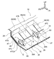
- the lower main body 47 of the lower ductility member 46 constituting the lower side of the ductility member 40 is joined to the upper surface of each inclined wall 28 of the lower frame 26. More specifically, the lower ductile member 46 has a lower main body portion 47 having a rectangular frame shape, and a lower surface of a protruding portion 47B (including an upright portion 47C) described later of the lower main body portion 47 is lower. The upper surface of the inclined wall 28 of the frame 26 is joined by an adhesive G (see FIGS. 1 and 3).
- the core frame 30 is disposed inside the lower main body portion 47, and in this state, the lower surface of the main body portion 32 is joined to the upper surface of the bottom plate 27 of the lower frame 26 with an adhesive.
- both ends of the lower body 47 in the longitudinal direction of the vehicle body are convex portions 47A having a substantially hat-shaped cross section extending in the vehicle width direction, and the upper surface of the convex portion 47A is each convex portion of the core frame 30. Together with the upper surface of 33, it is joined to the lower surface of the top plate 23 of the upper frame 22 with an adhesive.
- the vehicle is inclined at the same angle as the inclined wall 28 with respect to the horizontal direction (from the vehicle width direction outer upper side toward the vehicle width direction inner lower side).
- a rectangular flat-shaped projecting portion 47B that projects to the outside is integrally formed.
- a part of the overhanging portion 47B (lower body portion 47) corresponding to (opposed to) the projecting portion 34 of the core frame 30 is gradually increased from the inclined wall 28 from the outer side in the vehicle width direction to the inner side in the vehicle width direction.
- An upright portion 47C cut and raised so as to be separated is formed.
- a plurality of (for example, five) standing portions 47C are bent or curved at predetermined intervals in the longitudinal direction of the vehicle body (for example, at equal intervals) in the overhanging portion 47B. It is inserted into each protrusion 34. And the lower surface in the side of the protrusion part 34 of the main-body part 32 of the core frame 30 is joined to the upper surface of the overhang
- the vehicle width direction inner end portion of the upright portion 47C also has a predetermined angle (the angle of the inclined wall 28) from the vehicle width direction outer side upper side to the vehicle width direction inner side lower side with respect to the horizontal direction. Is inclined at a gentler angle).
- the water droplets that have entered the projecting portion 34 travel along the upper surface of the standing portion 47C and flow down to the inner side in the vehicle width direction from the standing portion 47C. That is, rust due to galvanic corrosion hardly occurs on the upper surface of the standing portion 47C and the inner end portion in the vehicle width direction (particularly, the lower ridge line portion 47Cd).
- the adhesive G for joining the upright portion 47C to the inclined wall 28 is gradually thicker from the outside in the vehicle width direction to the inside in the vehicle width direction.
- the vehicle width of the adhesive G does not contact the lower ridge line portion 47Cd of the standing portion 47C.
- a maximum thickness (a distance between the lower ridge line portion 47Cd and the inclined wall 28) H at the inner end in the direction is determined. Accordingly, the occurrence of rust due to galvanic corrosion at the lower ridge line portion 47Cd of the standing portion 47C is suppressed or prevented.
- the adhesive G protrudes from the inner end portion of the upright portion 47C in the vehicle width direction, and the protruding portion protrudes.
- the rising edge portion 47C may cover the vehicle width direction inner side end portion (particularly the lower ridge line portion 47Cd) of the standing portion 47C. According to this, the occurrence of rust due to galvanic corrosion is further suppressed or prevented particularly in the lower ridge line portion 47Cd of the standing portion 47C.
- an outer end in the vehicle width direction of the resin plate member 80 that protrudes inward in the vehicle width direction from the inner end in the vehicle width direction of the upright portion 47C is previously provided on the upper surface of the upright portion 47C with a double-sided tape or the like. Paste it.
- a part of the adhesive G protruding from the inner end in the vehicle width direction of the standing portion 47C is suppressed by the plate member 80, so that water droplets that have entered the protruding portion 34 are caused to rise in the standing portion 47C.
- the upper surface of the plate member 80 it flows down from the plate member 80 inward in the vehicle width direction.
- the lower ridge line portion 47Cd is covered with the adhesive G protruding from the vehicle width direction inner side end portion of the upright portion 47C, and the lower frame 26 is removed from the upper surface of the upright portion 47C by the plate member 80.
- a water droplet path toward the upper surface is formed. Therefore, even if the vehicle width direction inner side end portion (particularly the lower ridge line portion 47Cd) of the standing portion 47C is covered with the adhesive G, it is possible to prevent water droplets from remaining on the upper surface of the standing portion 47C. Generation of rust due to galvanic corrosion on the upper surface of 47C is suppressed or prevented.
- the thickness of the plate member 80 is 0.5 mm, for example, and the thickness of the double-sided tape is 0.2 mm, for example.
- the illustrated plate member 80 is affixed to the center of the upright portion 47C in the width direction (vehicle body longitudinal direction), the affixing position of the plate member 80 is not limited to this position.
- the lower frame 26 on the inner side in the vehicle width direction than the plate member 80 is formed with, for example, a circular through hole 26A. Therefore, the water droplets that have flowed down to the upper surface of the lower frame 26 through the upper surface of the standing portion 47C and the upper surface of the plate member 80 are discharged from the through hole 26A to the outside of the battery frame 20.
- the vehicle width direction outer side portion of the lower ductile member 46 from the projecting portion 47 ⁇ / b> B of the lower main body portion 47 extends along the side wall portion 29 of the lower frame 26.
- the side wall portion 47D is formed substantially vertically toward the side.
- the height of the side wall portion 47D is substantially the same as that of the side wall portion 29 that is the outer end portion of the lower frame 26 in the vehicle width direction.
- the side wall portion 29 of the lower frame 26 extends toward the upper side of the vehicle body to a height position that substantially reaches the boundary portion 49 between the side wall portion 47D of the lower body portion 47 and the lower flange portion 48. Further, a lower flange portion 48 that protrudes outward in the vehicle width direction from an end surface portion 38 of the core frame 30 and an upper end portion (battery frame 20) of the side wall portion 29 of the lower frame 26 is formed at the vehicle width direction outer end portion of the side wall portion 47D. It is connected continuously.
- the upper flange portion 44 and the lower flange portion 48 projecting outward from the battery frame 20 in the vehicle width direction are overlapped with each other and joined by an adhesive (or rivet or the like).
- a flange portion 50 serving as a fixing portion with the under member 14 (the lower surface side of the floor panel 12) is configured.
- the ductile member 40 (the upper ductile member 42 and the lower ductile member 46) is made of metal, and is formed of a high-tensile steel plate or an ultra-high-tensile steel plate as an example.
- the flange portion 50 constituted by the upper flange portion 44 and the lower flange portion 48 has a plurality of through holes 50 ⁇ / b> A for communicating with each other and allowing the flange bolts 58 to be inserted therethrough. It is formed along. Therefore, by inserting the flange bolt 58 through the through hole 50A and the through hole 14A from the lower side of the vehicle body and screwing into the weld nut 52, the battery frame 20 is attached to the under member 14 via the ductile member 40 (flange portion 50). Fastened and fixed.
- An inclined portion 44 ⁇ / b> A is formed (toward the boundary 45 between the upper main body portion 43 and the upper flange portion 44).
- the boundary portion 45 serves as a fulcrum for bending deformation, which will be described later, of the flange portion 50.
- the lower flange portion 48 that is overlapped and joined to the upper flange portion 44 is on the lower body portion 47 side, and on the outer side in the vehicle width direction with respect to the battery frame 20, at the same angle as the inclined portion 44A.
- An inclined portion 48 ⁇ / b> A is formed inwardly downward in the vehicle width direction (toward a boundary portion 49 between the lower main body portion 47 and the lower flange portion 48).
- the boundary part 49 becomes a structure used as the fulcrum of bending deformation of the flange part 50 with the boundary part 45. As shown in FIG.
- the outer end portion of the floor panel 12 in the vehicle width direction is a bent portion 12A formed to bend upward in the vehicle body, and the bent portion 12A is an inner portion of a metal rocker 60.
- the panel 62 is joined by welding or the like.
- the rocker 60 includes an inner panel 62 having a substantially hat-shaped cross section and an outer panel 64 having a substantially hat-shaped cross section.
- the upper flange portion 64A of the outer panel 64 is joined to the upper flange portion 62A of the inner panel 62 by welding or the like, and the lower flange portion 64B of the outer panel 64 is joined to the lower flange portion 62B of the inner panel 62 by welding or the like.
- a rectangular closed cross-sectional shape is formed.
- a metal energy absorbing member 70 is disposed between the lower side of the rocker 60 (including both ends of the floor panel 12 in the vehicle width direction) and the battery frame 20.
- the energy absorbing member 70 can insert an inner member 72 disposed on the inner side in the vehicle width direction so as to be close to the side wall portion 29, and a predetermined gap (lower flange portions 62B and 64B) on the outer side in the vehicle width direction with respect to the inner member 72.
- an outer member 76 arranged with a gap of a certain degree.
- the inner member 72 is configured in such a shape that a plurality of (for example, seven) block portions having a substantially rectangular closed cross-sectional shape (cylindrical shape) extending in the longitudinal direction of the vehicle body are combined, and the innermost side in the vehicle width direction.
- a side wall portion 73A facing the inner side in the vehicle width direction of the block portion 73 is disposed close to the side wall portion 29 (disposed with a slight gap in the vehicle width direction).
- the block portion 73 is fastened and fixed to the under member 14 except for the fastening portion of the flange portion 50 by bolts and weld nuts (not shown), and the block portion 74 on the outermost side in the vehicle width direction is the inner panel of the rocker 60. Fastened to 62 by bolts 66 and weld nuts 68. As a result, the inner member 72 is arranged on the vehicle body lower side at both ends of the floor panel 12 in the vehicle width direction.
- the outer member 76 is configured in such a shape that a plurality of (for example, five) block portions having a substantially rectangular closed cross-sectional shape (cylindrical shape) extending in the longitudinal direction of the vehicle body are integrally combined.
- the upper block portion 79 is fastened and fixed to the outer panel 64 of the rocker 60 with bolts 66 and weld nuts 68.
- the outer member 76 is arranged on the vehicle body lower side of the rocker 60.
- a convex portion 75A that protrudes outward in the vehicle width direction is formed in the lower block portion 75 at the outermost side in the vehicle width direction of the inner member 72. Then, at the inner side in the vehicle width direction of the outer member 76, the vehicle is arranged so as to allow the convex portion 75 ⁇ / b> A at the boundary portion between the lower block portion 77 and the block portion 78 (so as not to contact the convex portion 75 ⁇ / b> A) A recess 77A that is recessed outward in the width direction is formed.
- the concave portion 77A is adapted to be fitted (contacted) with the convex portion 75A when the outer member 76 moves to the inner member 72 side due to a side collision of the vehicle.
- the member 76 can be efficiently transmitted to the inner member 72. That is, the outer member 76 and the inner member 72 are integrated and can be plastically deformed (collapsed) inward in the vehicle width direction.
- the flange portion 50 (the upper flange portion 44 and the lower flange portion 48) of the ductile member 40 fastened and fixed to the under member 14 is located above the boundary portion 45 between the upper main body portion 43 and the upper flange portion 44 as a fulcrum. A force is applied so as to be bent (the outer end of the flange portion 50 in the vehicle width direction is moved upward).
- the flange portion 50 (the ductile member 40) has ductility because it is formed of metal (high-tensile steel plate or ultra-high-tensile steel plate). Further, on the upper body portion 43 side of the upper flange portion 44 constituting the flange portion 50 and the lower body portion 47 side of the lower flange portion 48 and on the outer side in the vehicle width direction than the battery frame 20, Inclined portions 44A and 48A are formed inward in the width direction and downward.
- the flange portion 50 is easily bent and deformed upward with respect to the boundary portions 45 and 49 as the fulcrum. Therefore, the bending moment M input to the flange portion 50 is efficiently absorbed by the bending deformation of the flange portion 50 toward the upper side of the vehicle body, and is prevented or prevented from being transmitted to the battery frame 20. That is, it is possible to reduce or eliminate the stress load applied from the under member 14 to the battery frame 20 through the flange portion 50 at the time of a side collision of the vehicle.
- the flange portion 50 since the flange portion 50 has ductility, it is only bent and deformed upward of the vehicle body, and there is no fear of breaking (the flange portion 50 is suppressed or prevented from being broken). Therefore, there is no possibility that the battery frame 20 is detached from the under member 14, and there is no possibility that the fuel cell stack 16 is detached from the vehicle.
- the energy absorbing member 70 (the outer member 76 and the inner member 72) moves while being plastically deformed inward in the vehicle width direction. A part is absorbed and a part of the remaining collision load is transmitted to the under member 14 and the battery frame 20.
- the inclined wall 28 is not formed at the outer end portion of the lower frame 126 in the vehicle width direction. That is, only the side wall portion 129 extending substantially vertically upward is formed at the outer end portion of the bottom plate 127 in the vehicle width direction.
- projection part 147B in the lower main-body part 147 of the lower ductility member 146 is projected inward in the vehicle width direction along the horizontal direction, and is joined to the upper surface of the bottom plate 127, and side wall part 147D in the lower main-body part 147 is It extends substantially vertically upward and is joined to the inner surface of the side wall portion 129.
- the block portion 173 of the inner member 172 of the plastically deformed energy absorbing member 170 is rotated by the bending moment M while rotating the lower frame 126.
- the upper end part side of the side wall part 129 may be pressed inward in the vehicle width direction.
- the side wall part 129 and the side wall part 147D are deformed so as to fall inward in the vehicle width direction, and a part of the bottom plate 127 on the inner side in the vehicle width direction is broken than the inner end part in the vehicle width direction of the overhanging part 147B.
- a bending moment N directed upward is generated in a part of the bottom plate 127 where the proof stress changes suddenly without the overhanging portion 147B, and the battery frame 120 may collapse in cross section.
- the vehicle frame direction outer side of the lower frame 26 of the battery frame 20 extends from the vehicle width direction inner lower side to the vehicle width direction outer upper side.
- An inclined wall 28 that is inclined toward the vehicle width direction (from the upper side in the vehicle width direction to the lower side in the vehicle width direction) is formed, and a side wall portion 29 that extends substantially vertically upward at the vehicle width direction outer end of the inclined wall 28. Is formed.
- the overhanging portion 47B of the lower main body portion 47 is also inclined at the same angle as the inclined wall 28 and extends substantially vertically upward at the vehicle width direction outer side end portion of the overhanging portion 47B. 47D is formed. That is, the overhang 47B is joined to the upper surface of the inclined wall 28, and the side wall 47D is joined to the inner surface of the side wall 29.
- the collision load (indicated by an arrow F in FIG. 4). Is efficiently transmitted inward in the vehicle width direction along the in-plane direction (compression direction) of the inclined wall 28 (lower frame 26) and the overhanging portion 47B (lower main body portion 47). It is possible to suppress or prevent falling down inward in the width direction.
- an upright portion 47C that is separated from the inclined wall 28 as it goes inward in the vehicle width direction is formed in a part of the overhanging portion 47B, and an adhesive G for joining the upright portion 47C to the inclined wall 28 is applied to the vehicle. Since the thickness increases toward the inner side in the width direction, a part of the collision load transmitted by the inclined wall 28 and the overhanging portion 47B is suppressed by the adhesive G while suppressing a sudden change in yield strength due to the absence of the overhanging portion 47B. Can be absorbed. Therefore, the collision load transmitted to the bottom plate 27 can be reduced, and the cross-sectional collapse of the battery frame 20 (cracking of the bottom plate 27) can be suppressed or prevented as much as possible.
- the standing portion 47C is inclined from the upper outside in the vehicle width direction to the lower inner side in the vehicle width direction with respect to the horizontal direction, and the lower ridge line portion 47Cd at the inner end in the vehicle width direction is bonded to the inclined wall 28. Since the maximum thickness H of the agent G is separated, even if there are water droplets in the projecting portion 34, the water droplets flow down the upper surface of the standing portion 47C and adhere to the upper surface of the standing portion 47C and the lower ridge line portion 47Cd. It is difficult (see FIG. 3). Therefore, rust due to galvanic corrosion hardly occurs on the upper surface of the standing portion 47C and the lower ridge line portion 47Cd.
- the vehicle battery mounting structure 10 it is not necessary to take measures such as applying a sealer to the inner end of the upright portion 47C in the vehicle width direction.
- the adhesive G protrudes from the vehicle width direction inner end portion of the standing portion 47C, and the protruding adhesive G covers the vehicle width direction inner end portion (particularly the lower ridge line portion 47Cd) of the standing portion 47C. It is also possible (see FIGS. 5 and 6). According to this, it is possible to further suppress or prevent the occurrence of rust due to galvanic corrosion at the lower ridge line portion 47Cd of the standing portion 47C.
- the plate member 80 is provided on the upper surface of the standing portion 47C so as to protrude inward in the vehicle width direction from the vehicle width direction inner end portion of the standing portion 47C, the vehicle width direction inner end of the standing portion 47C. Part of the adhesive G protruding from the portion can be suppressed by the plate member 80. That is, the water droplet path can be formed even in a closed cross-sectional shape in which it is difficult to level the adhesive G after bonding and form a water droplet path.
- the water droplets flow down from the upper surface of the standing portion 47 ⁇ / b> C and the upper surface of the plate member 80 to the upper surface of the lower frame 26, and from the through holes 26 ⁇ / b> A formed in the lower frame 26. 20 is discharged to the outside. Therefore, it is possible to further suppress or prevent the occurrence of rust due to galvanic corrosion on the upper surface of the standing portion 47C.
- the overhanging portion 47B of the lower duct member 46 in the lower main body portion 47 is sandwiched and fixed between the core frame 30 (main body portion 32) and the lower frame 26 (bottom plate 27). Therefore, even when the flange portion 50 is bent and deformed toward the upper side of the vehicle body at the time of a side collision of the vehicle, the protruding portion 47B of the lower main body portion 47 is suppressed or prevented from being peeled off from the core frame 30 and the lower frame 26. .
- the upper flange portion 44 on the outer side in the vehicle width direction with respect to the battery frame 20, on the upper body portion 43 side, that is, the boundary portion 45 between the upper body portion 43 and the upper flange portion 44, is substantially “U” when viewed from the front-rear direction of the vehicle body. You may make it form the recessed part (illustration omitted) which becomes character shape (the boundary part 45 is substantially circular arc shape by sectional view), or substantially "V" character shape.
- the outer end in the vehicle width direction of the flange portion 50 is more easily bent and deformed toward the vehicle body upper side with the boundary portion 45 between the upper main body portion 43 and the upper flange portion 44, that is, the concave portion as a fulcrum.
- the stress load applied to the battery frame 20 from the under member 14 via the flange portion 50 can be further reduced or eliminated.
- the vehicle battery mounting structure 10 has been described based on the drawings, but the vehicle battery mounting structure 10 according to the present embodiment is not limited to the illustrated one, and The design can be changed as appropriate without departing from the scope of the invention.
- the ductile member 40 is not limited to one formed from a high-tensile steel plate or an ultra-high-strength steel plate, and may be formed from an aluminum alloy or iron having a certain degree of hardness.
- the flange portion 50 of the ductile member 40 is not limited to a configuration in which the flange portion 50 is fastened and fixed to the under member 14 bonded and fixed to the lower surface of the floor panel 12.
- the lower surface of the floor panel 12 or the lower surface of the under member 14 is used. It is good also as a structure fastened and fixed to the bracket etc. which are being fixedly joined to (not shown). That is, the flange portion 50 of the ductile member 40 may be configured to be indirectly joined to the floor panel 12 or the under member 14.
- the upper main body 43 and the lower main body 47 of the ductile member 40 are not limited to those bonded to the battery frame 20 by an adhesive, and may be configured to be bonded by a bonding device such as a rivet, for example.
- the battery frame 20 in the present embodiment is not limited to the one that supports the fuel cell stack 16.
Landscapes
- Engineering & Computer Science (AREA)
- Chemical & Material Sciences (AREA)
- Combustion & Propulsion (AREA)
- Transportation (AREA)
- Mechanical Engineering (AREA)
- Body Structure For Vehicles (AREA)
- Arrangement Or Mounting Of Propulsion Units For Vehicles (AREA)
Abstract
Description
Claims (5)
- フロアパネルの下方側に設けられたエネルギー吸収部材の車幅方向内側に配置され、電池を支持するバッテリフレームをバッテリフレームアッパと共に構成する樹脂製のバッテリフレームロアと、
前記バッテリフレームロアの車幅方向外側端部に接合されるロア本体部と前記フロアパネルの下面側に固定されるロアフランジ部とを有する下部延性部材と、
前記バッテリフレームロアの車幅方向外側端部に形成され、車幅方向外側上方から車幅方向内側下方へ向けて傾斜した傾斜壁と、
を備えた車両用電池搭載構造。 - 前記ロア本体部の一部は、車幅方向外側から車幅方向内側へ向けて徐々に前記傾斜壁から離隔する起立部とされ、前記傾斜壁と前記起立部との間が接着剤で埋められて接合されている請求項1に記載の車両用電池搭載構造。
- 前記起立部の車幅方向内側端部から車幅方向内側へ突出するプレート部材が、前記起立部に設けられている請求項2に記載の車両用電池搭載構造。
- 前記傾斜壁の車幅方向外側端部には、上方に向かって延在する縦壁が形成されている請求項1~請求項3の何れか1項に記載の車両用電池搭載構造。
- 前記バッテリフレームアッパの車幅方向外側端部に接合されるアッパ本体部と前記ロアフランジ部と共に前記フロアパネルの下面側に固定されるアッパフランジ部とを有する上部延性部材を備え、
前記アッパフランジ部の前記アッパ本体部側には、車幅方向外側上方から車幅方向内側下方へ向けて傾斜する傾斜部が形成されている請求項1~請求項4の何れか1項に記載の車両用電池搭載構造。
Priority Applications (4)
| Application Number | Priority Date | Filing Date | Title |
|---|---|---|---|
| US15/036,091 US9809100B2 (en) | 2013-12-02 | 2014-11-06 | Vehicle battery mounting structure |
| JP2015516134A JP5930123B2 (ja) | 2013-12-02 | 2014-11-06 | 車両用電池搭載構造 |
| DE112014005490.9T DE112014005490B4 (de) | 2013-12-02 | 2014-11-06 | Fahrzeugbatterie-Befestigungsstruktur |
| CN201480065621.6A CN105992702B (zh) | 2013-12-02 | 2014-11-06 | 车辆用电池搭载结构 |
Applications Claiming Priority (2)
| Application Number | Priority Date | Filing Date | Title |
|---|---|---|---|
| JP2013-249391 | 2013-12-02 | ||
| JP2013249391 | 2013-12-02 |
Publications (1)
| Publication Number | Publication Date |
|---|---|
| WO2015083487A1 true WO2015083487A1 (ja) | 2015-06-11 |
Family
ID=53273258
Family Applications (1)
| Application Number | Title | Priority Date | Filing Date |
|---|---|---|---|
| PCT/JP2014/079496 Ceased WO2015083487A1 (ja) | 2013-12-02 | 2014-11-06 | 車両用電池搭載構造 |
Country Status (5)
| Country | Link |
|---|---|
| US (1) | US9809100B2 (ja) |
| JP (1) | JP5930123B2 (ja) |
| CN (1) | CN105992702B (ja) |
| DE (1) | DE112014005490B4 (ja) |
| WO (1) | WO2015083487A1 (ja) |
Cited By (9)
| Publication number | Priority date | Publication date | Assignee | Title |
|---|---|---|---|---|
| JP2016043926A (ja) * | 2014-08-25 | 2016-04-04 | ベンテラー・アウトモビールテヒニク・ゲゼルシャフト・ミト・ベシュレンクテル・ハフツング | 原動機付き車両用のクロスメンバ及びクロスメンバを製造するための方法 |
| JP2017100375A (ja) * | 2015-12-02 | 2017-06-08 | 本田技研工業株式会社 | 金属部材およびfrp部材の接着構造体 |
| CN110733325A (zh) * | 2018-07-03 | 2020-01-31 | 丰田自动车株式会社 | 车辆前部结构 |
| EP3795399A4 (en) * | 2018-11-27 | 2021-06-16 | Contemporary Amperex Technology Co., Limited | BATTERY COMPARTMENT AND VEHICLE |
| US11447184B2 (en) | 2020-01-17 | 2022-09-20 | Toyota Jidosha Kabushiki Kaisha | Vehicle body lower structure |
| US20230014338A1 (en) * | 2019-06-28 | 2023-01-19 | Faurecia Systemes D'echappement | Electrical storage battery and vehicle |
| JP2023141197A (ja) * | 2022-03-23 | 2023-10-05 | 株式会社神戸製鋼所 | 電動車両用バッテリーケース構造およびその製造方法 |
| JP2024013636A (ja) * | 2022-07-20 | 2024-02-01 | トヨタ自動車株式会社 | 床下部品の保護構造 |
| DE102017129845B4 (de) | 2016-12-14 | 2024-03-28 | Denso Corporation | Batteriepackung, die mit einem Stoßabsorbieraufbau versehen ist |
Families Citing this family (28)
| Publication number | Priority date | Publication date | Assignee | Title |
|---|---|---|---|---|
| JP5870992B2 (ja) * | 2013-12-25 | 2016-03-01 | トヨタ自動車株式会社 | 車両用電池搭載構造 |
| JP5900481B2 (ja) * | 2013-12-25 | 2016-04-06 | トヨタ自動車株式会社 | 車両パネル構造 |
| JP6512163B2 (ja) * | 2016-04-21 | 2019-05-15 | トヨタ自動車株式会社 | 車両のバッテリ搭載構造 |
| CN206201948U (zh) * | 2016-08-31 | 2017-05-31 | 比亚迪股份有限公司 | 一种车用托盘组件、车用电池包体和汽车 |
| EP3326853B1 (de) * | 2016-11-23 | 2020-04-29 | MAGNA STEYR Fahrzeugtechnik AG & Co KG | Batterie-halteanordnung |
| JP6555235B2 (ja) * | 2016-11-30 | 2019-08-07 | トヨタ自動車株式会社 | 車体下部構造 |
| JP6866784B2 (ja) * | 2017-06-27 | 2021-04-28 | トヨタ自動車株式会社 | 車体下部構造 |
| JP6859933B2 (ja) * | 2017-11-17 | 2021-04-14 | トヨタ自動車株式会社 | 車両用電池ケース及びその製造方法 |
| KR102440612B1 (ko) * | 2017-12-15 | 2022-09-05 | 현대자동차 주식회사 | 측방 차체 보강구조 |
| JP6973172B2 (ja) * | 2018-02-26 | 2021-11-24 | トヨタ自動車株式会社 | 接合構造 |
| JP7067142B2 (ja) * | 2018-03-09 | 2022-05-16 | トヨタ自動車株式会社 | 車両下部構造 |
| DE102018109296B3 (de) | 2018-04-19 | 2019-09-12 | Dr. Ing. H.C. F. Porsche Aktiengesellschaft | Elektrisch oder teilelektrisch antreibbares Fahrzeug |
| DE102018109508A1 (de) * | 2018-04-20 | 2019-10-24 | Bayerische Motoren Werke Aktiengesellschaft | Befestigungsvorrichtung zum Befestigen eines Hochvoltspeichergehäuses an einem Rohbauteil eines Kraftfahrzeugs sowie Hochvoltspeichergehäuse |
| DE102018213009A1 (de) * | 2018-08-03 | 2020-02-06 | Bayerische Motoren Werke Aktiengesellschaft | Befestigungsanordnung für eine Fahrzeugbatterie an einer Karosserie eines Kraftfahrzeugs sowie Verfahren zur Montage einer Fahrzeugbatterie in einem Kraftfahrzeug |
| US10494030B1 (en) * | 2018-08-20 | 2019-12-03 | Ford Global Technologies, Llc | Collapsible battery pack support assembly and supporting method |
| DE102018217649B4 (de) * | 2018-10-15 | 2022-01-05 | Volkswagen Aktiengesellschaft | Karosseriestruktur für ein Fahrzeug |
| US11007899B2 (en) * | 2018-10-23 | 2021-05-18 | Chongqing Jinkang New Energy Vehicle Co., Ltd | Mounting structures for battery packs in electric vehicles |
| WO2020128565A1 (en) | 2018-12-17 | 2020-06-25 | Arcelormittal | Front floor reinforcement structure for a vehicle having a battery pack in the tunnel |
| DE102018133049B4 (de) * | 2018-12-20 | 2022-04-21 | Bayerische Motoren Werke Aktiengesellschaft | Seitenschweller für einen Kraftwagen |
| US10720620B1 (en) * | 2019-01-15 | 2020-07-21 | Ford Global Technologies, Llc | High voltage battery pack mounting systems for providing load path management during impact loading events |
| JP2021054286A (ja) * | 2019-09-30 | 2021-04-08 | トヨタ自動車株式会社 | 車両下部構造 |
| JP7413844B2 (ja) * | 2020-03-03 | 2024-01-16 | トヨタ自動車株式会社 | 車両下部構造 |
| US11584238B2 (en) * | 2020-09-22 | 2023-02-21 | Ford Global Technologies, Llc | Passive structural stopper bracket |
| US12115847B2 (en) * | 2022-05-04 | 2024-10-15 | Ford Global Technologies, Llc | Battery housing assembly having strike bar |
| CN114872555A (zh) * | 2022-06-06 | 2022-08-09 | 江铃汽车股份有限公司 | 一种电池包防撞装置及其防撞结构 |
| DE102022118289A1 (de) * | 2022-07-21 | 2024-02-01 | Bayerische Motoren Werke Aktiengesellschaft | Energiespeicher-Bodengruppe für einen elektrisch antreibbaren Kraftwagen |
| JP2024036144A (ja) * | 2022-09-05 | 2024-03-15 | トヨタ自動車株式会社 | 車両 |
| DE102023131042B3 (de) | 2023-11-09 | 2024-10-24 | Dr. Ing. H.C. F. Porsche Aktiengesellschaft | Karosserieanordnung für ein Elektrofahrzeug sowie Elektrofahrzeug |
Citations (5)
| Publication number | Priority date | Publication date | Assignee | Title |
|---|---|---|---|---|
| JPH07246845A (ja) * | 1994-03-14 | 1995-09-26 | Nissan Motor Co Ltd | 電気自動車のバッテリフレーム取付構造 |
| JP2013103635A (ja) * | 2011-11-15 | 2013-05-30 | Honda Motor Co Ltd | 自動車の車体下部構造 |
| JP2013123956A (ja) * | 2011-12-13 | 2013-06-24 | Toyota Motor Corp | 車両用電池搭載構造 |
| JP2013133046A (ja) * | 2011-12-27 | 2013-07-08 | Toyota Motor Corp | 車両用電池搭載構造 |
| US20130270864A1 (en) * | 2012-04-13 | 2013-10-17 | Tesla Motor Inc. | Localized Energy Dissipation Structures For Vehicles |
Family Cites Families (17)
| Publication number | Priority date | Publication date | Assignee | Title |
|---|---|---|---|---|
| US5725272A (en) | 1996-06-27 | 1998-03-10 | Sika Corporation | Drain assembly for acoustic baffle system |
| JP4396335B2 (ja) | 2004-03-15 | 2010-01-13 | 日産自動車株式会社 | 異種金属パネルの接合構造および接合方法 |
| JP4308285B2 (ja) | 2007-07-17 | 2009-08-05 | 本田技研工業株式会社 | サブフレーム構造 |
| JP2009221399A (ja) | 2008-03-18 | 2009-10-01 | Toyota Motor Corp | 接着部材の接着方法 |
| JP2010032030A (ja) | 2008-07-31 | 2010-02-12 | Toray Ind Inc | 接着構造体およびその製作方法 |
| JP5013140B2 (ja) | 2009-12-10 | 2012-08-29 | 三菱自動車工業株式会社 | バッテリーケース |
| DE102010011890A1 (de) | 2010-03-18 | 2011-09-22 | Audi Ag | Trägerstruktur zur Befestigung eines Energiespeichermoduls, inbesondere eines Batteriemoduls in einem Kraftfahrzeug |
| EP2676869B1 (en) * | 2011-02-15 | 2014-10-22 | Toyota Jidosha Kabushiki Kaisha | Structure for lower portion of vehicle |
| JP5375886B2 (ja) * | 2011-07-26 | 2013-12-25 | トヨタ自動車株式会社 | 自動車の電池保護構造 |
| JP5824997B2 (ja) | 2011-09-14 | 2015-12-02 | トヨタ自動車株式会社 | 車両用電池搭載構造 |
| US8833839B2 (en) * | 2012-04-13 | 2014-09-16 | Toyota Motor Engineering & Manufacturing North America, Inc. | Impact protection structures for vehicles |
| JP5708567B2 (ja) | 2012-06-14 | 2015-04-30 | トヨタ自動車株式会社 | 車両用電池搭載構造 |
| JP6070046B2 (ja) | 2012-10-16 | 2017-02-01 | トヨタ自動車株式会社 | 車両用電池搭載構造 |
| US9281505B2 (en) | 2012-10-16 | 2016-03-08 | Toyota Jidosha Kabushiki Kaisha | Battery mounting structure for vehicle |
| JP6197363B2 (ja) * | 2013-05-20 | 2017-09-20 | 日産自動車株式会社 | バッテリ搭載車両 |
| JP5817791B2 (ja) | 2013-06-28 | 2015-11-18 | トヨタ自動車株式会社 | 車体下部構造 |
| JP5752749B2 (ja) | 2013-07-03 | 2015-07-22 | トヨタ自動車株式会社 | パネル部材、プレス型、及びパネル部材の製造方法 |
-
2014
- 2014-11-06 JP JP2015516134A patent/JP5930123B2/ja active Active
- 2014-11-06 DE DE112014005490.9T patent/DE112014005490B4/de active Active
- 2014-11-06 CN CN201480065621.6A patent/CN105992702B/zh active Active
- 2014-11-06 WO PCT/JP2014/079496 patent/WO2015083487A1/ja not_active Ceased
- 2014-11-06 US US15/036,091 patent/US9809100B2/en active Active
Patent Citations (5)
| Publication number | Priority date | Publication date | Assignee | Title |
|---|---|---|---|---|
| JPH07246845A (ja) * | 1994-03-14 | 1995-09-26 | Nissan Motor Co Ltd | 電気自動車のバッテリフレーム取付構造 |
| JP2013103635A (ja) * | 2011-11-15 | 2013-05-30 | Honda Motor Co Ltd | 自動車の車体下部構造 |
| JP2013123956A (ja) * | 2011-12-13 | 2013-06-24 | Toyota Motor Corp | 車両用電池搭載構造 |
| JP2013133046A (ja) * | 2011-12-27 | 2013-07-08 | Toyota Motor Corp | 車両用電池搭載構造 |
| US20130270864A1 (en) * | 2012-04-13 | 2013-10-17 | Tesla Motor Inc. | Localized Energy Dissipation Structures For Vehicles |
Cited By (13)
| Publication number | Priority date | Publication date | Assignee | Title |
|---|---|---|---|---|
| JP2016043926A (ja) * | 2014-08-25 | 2016-04-04 | ベンテラー・アウトモビールテヒニク・ゲゼルシャフト・ミト・ベシュレンクテル・ハフツング | 原動機付き車両用のクロスメンバ及びクロスメンバを製造するための方法 |
| JP2017100375A (ja) * | 2015-12-02 | 2017-06-08 | 本田技研工業株式会社 | 金属部材およびfrp部材の接着構造体 |
| DE102017129845B4 (de) | 2016-12-14 | 2024-03-28 | Denso Corporation | Batteriepackung, die mit einem Stoßabsorbieraufbau versehen ist |
| CN110733325A (zh) * | 2018-07-03 | 2020-01-31 | 丰田自动车株式会社 | 车辆前部结构 |
| US11548365B2 (en) | 2018-11-27 | 2023-01-10 | Contemporary Amperex Technology Co., Limited | Battery tray and vehicle |
| US11148520B2 (en) | 2018-11-27 | 2021-10-19 | Contemporary Amperex Technology Co., Limited | Battery tray and vehicle |
| US11554654B2 (en) | 2018-11-27 | 2023-01-17 | Contemporary Amperex Technology Co., Limited | Battery tray and vehicle |
| EP3795399A4 (en) * | 2018-11-27 | 2021-06-16 | Contemporary Amperex Technology Co., Limited | BATTERY COMPARTMENT AND VEHICLE |
| US20230014338A1 (en) * | 2019-06-28 | 2023-01-19 | Faurecia Systemes D'echappement | Electrical storage battery and vehicle |
| US11447184B2 (en) | 2020-01-17 | 2022-09-20 | Toyota Jidosha Kabushiki Kaisha | Vehicle body lower structure |
| JP2023141197A (ja) * | 2022-03-23 | 2023-10-05 | 株式会社神戸製鋼所 | 電動車両用バッテリーケース構造およびその製造方法 |
| JP2024013636A (ja) * | 2022-07-20 | 2024-02-01 | トヨタ自動車株式会社 | 床下部品の保護構造 |
| JP7740151B2 (ja) | 2022-07-20 | 2025-09-17 | トヨタ自動車株式会社 | 床下部品の保護構造 |
Also Published As
| Publication number | Publication date |
|---|---|
| JP5930123B2 (ja) | 2016-06-08 |
| DE112014005490B4 (de) | 2026-02-05 |
| JPWO2015083487A1 (ja) | 2017-03-16 |
| CN105992702A (zh) | 2016-10-05 |
| US9809100B2 (en) | 2017-11-07 |
| DE112014005490T5 (de) | 2016-08-18 |
| CN105992702B (zh) | 2018-06-26 |
| US20160288636A1 (en) | 2016-10-06 |
Similar Documents
| Publication | Publication Date | Title |
|---|---|---|
| JP5930123B2 (ja) | 車両用電池搭載構造 | |
| JP5900480B2 (ja) | 車両用電池搭載構造 | |
| JP5870992B2 (ja) | 車両用電池搭載構造 | |
| JP5846193B2 (ja) | 車両用電池搭載構造 | |
| CN110588800B (zh) | 车身下部结构 | |
| JP6032258B2 (ja) | 車両用電池搭載構造 | |
| US9616937B2 (en) | Vehicle body structure | |
| JP5971235B2 (ja) | バッテリフレーム及び車両用電池搭載構造 | |
| JP6136187B2 (ja) | 車両用電池搭載構造 | |
| JP6299724B2 (ja) | サスペンションメンバ | |
| JP5821340B2 (ja) | 車両の前部車体構造 | |
| JP2018114910A (ja) | 自動車車両 | |
| WO2014061109A1 (ja) | 車両用電池搭載構造 | |
| CN117480677A (zh) | 电池壳体结构和电池壳体结构的制造方法 | |
| JP2023030757A (ja) | 車体下部構造 | |
| JP2012214112A (ja) | 自動車ルーフパネル | |
| JP5846095B2 (ja) | カウル構造 | |
| JP2009067075A (ja) | 車両後部構造 | |
| JP2025062247A (ja) | バッテリーケース | |
| JP6698567B2 (ja) | バンパリインフォースメント | |
| JP2014051169A (ja) | 車体後部構造 |
Legal Events
| Date | Code | Title | Description |
|---|---|---|---|
| ENP | Entry into the national phase |
Ref document number: 2015516134 Country of ref document: JP Kind code of ref document: A |
|
| 121 | Ep: the epo has been informed by wipo that ep was designated in this application |
Ref document number: 14868074 Country of ref document: EP Kind code of ref document: A1 |
|
| WWE | Wipo information: entry into national phase |
Ref document number: 15036091 Country of ref document: US |
|
| WWE | Wipo information: entry into national phase |
Ref document number: 112014005490 Country of ref document: DE |
|
| 122 | Ep: pct application non-entry in european phase |
Ref document number: 14868074 Country of ref document: EP Kind code of ref document: A1 |
|
| WWG | Wipo information: grant in national office |
Ref document number: 112014005490 Country of ref document: DE |