US11148520B2 - Battery tray and vehicle - Google Patents

Battery tray and vehicle Download PDF

Info

Publication number
US11148520B2
US11148520B2 US17/133,594 US202017133594A US11148520B2 US 11148520 B2 US11148520 B2 US 11148520B2 US 202017133594 A US202017133594 A US 202017133594A US 11148520 B2 US11148520 B2 US 11148520B2
Authority
US
United States
Prior art keywords
reinforcing
battery tray
base plate
reinforcing block
reinforcing beam
Prior art date
Legal status (The legal status is an assumption and is not a legal conclusion. Google has not performed a legal analysis and makes no representation as to the accuracy of the status listed.)
Active
Application number
US17/133,594
Other versions
US20210114449A1 (en
Inventor
Yannan CHU
Jinqing JI
Mu Qian
Jiubiao LIN
Current Assignee (The listed assignees may be inaccurate. Google has not performed a legal analysis and makes no representation or warranty as to the accuracy of the list.)
Contemporary Amperex Technology Co Ltd
Original Assignee
Contemporary Amperex Technology Co Ltd
Priority date (The priority date is an assumption and is not a legal conclusion. Google has not performed a legal analysis and makes no representation as to the accuracy of the date listed.)
Filing date
Publication date
Application filed by Contemporary Amperex Technology Co Ltd filed Critical Contemporary Amperex Technology Co Ltd
Assigned to CONTEMPORARY AMPEREX TECHNOLOGY CO., LIMITED reassignment CONTEMPORARY AMPEREX TECHNOLOGY CO., LIMITED ASSIGNMENT OF ASSIGNORS INTEREST (SEE DOCUMENT FOR DETAILS). Assignors: QIAN, Mu, CHU, YANNAN, JI, Jinqing, Lin, Jiubiao
Publication of US20210114449A1 publication Critical patent/US20210114449A1/en
Priority to US17/462,727 priority Critical patent/US11548365B2/en
Priority to US17/462,827 priority patent/US11554654B2/en
Application granted granted Critical
Publication of US11148520B2 publication Critical patent/US11148520B2/en
Active legal-status Critical Current
Anticipated expiration legal-status Critical

Links

Images

Classifications

    • HELECTRICITY
    • H01ELECTRIC ELEMENTS
    • H01MPROCESSES OR MEANS, e.g. BATTERIES, FOR THE DIRECT CONVERSION OF CHEMICAL ENERGY INTO ELECTRICAL ENERGY
    • H01M50/00Constructional details or processes of manufacture of the non-active parts of electrochemical cells other than fuel cells, e.g. hybrid cells
    • H01M50/20Mountings; Secondary casings or frames; Racks, modules or packs; Suspension devices; Shock absorbers; Transport or carrying devices; Holders
    • H01M50/249Mountings; Secondary casings or frames; Racks, modules or packs; Suspension devices; Shock absorbers; Transport or carrying devices; Holders specially adapted for aircraft or vehicles, e.g. cars or trains
    • BPERFORMING OPERATIONS; TRANSPORTING
    • B60VEHICLES IN GENERAL
    • B60KARRANGEMENT OR MOUNTING OF PROPULSION UNITS OR OF TRANSMISSIONS IN VEHICLES; ARRANGEMENT OR MOUNTING OF PLURAL DIVERSE PRIME-MOVERS IN VEHICLES; AUXILIARY DRIVES FOR VEHICLES; INSTRUMENTATION OR DASHBOARDS FOR VEHICLES; ARRANGEMENTS IN CONNECTION WITH COOLING, AIR INTAKE, GAS EXHAUST OR FUEL SUPPLY OF PROPULSION UNITS IN VEHICLES
    • B60K1/00Arrangement or mounting of electrical propulsion units
    • B60K1/04Arrangement or mounting of electrical propulsion units of the electric storage means for propulsion
    • HELECTRICITY
    • H01ELECTRIC ELEMENTS
    • H01MPROCESSES OR MEANS, e.g. BATTERIES, FOR THE DIRECT CONVERSION OF CHEMICAL ENERGY INTO ELECTRICAL ENERGY
    • H01M50/00Constructional details or processes of manufacture of the non-active parts of electrochemical cells other than fuel cells, e.g. hybrid cells
    • H01M50/20Mountings; Secondary casings or frames; Racks, modules or packs; Suspension devices; Shock absorbers; Transport or carrying devices; Holders
    • H01M50/204Racks, modules or packs for multiple batteries or multiple cells
    • H01M50/207Racks, modules or packs for multiple batteries or multiple cells characterised by their shape
    • H01M50/211Racks, modules or packs for multiple batteries or multiple cells characterised by their shape adapted for pouch cells
    • HELECTRICITY
    • H01ELECTRIC ELEMENTS
    • H01MPROCESSES OR MEANS, e.g. BATTERIES, FOR THE DIRECT CONVERSION OF CHEMICAL ENERGY INTO ELECTRICAL ENERGY
    • H01M50/00Constructional details or processes of manufacture of the non-active parts of electrochemical cells other than fuel cells, e.g. hybrid cells
    • H01M50/20Mountings; Secondary casings or frames; Racks, modules or packs; Suspension devices; Shock absorbers; Transport or carrying devices; Holders
    • H01M50/218Mountings; Secondary casings or frames; Racks, modules or packs; Suspension devices; Shock absorbers; Transport or carrying devices; Holders characterised by the material
    • H01M50/22Mountings; Secondary casings or frames; Racks, modules or packs; Suspension devices; Shock absorbers; Transport or carrying devices; Holders characterised by the material of the casings or racks
    • H01M50/222Inorganic material
    • H01M50/224Metals
    • HELECTRICITY
    • H01ELECTRIC ELEMENTS
    • H01MPROCESSES OR MEANS, e.g. BATTERIES, FOR THE DIRECT CONVERSION OF CHEMICAL ENERGY INTO ELECTRICAL ENERGY
    • H01M50/00Constructional details or processes of manufacture of the non-active parts of electrochemical cells other than fuel cells, e.g. hybrid cells
    • H01M50/20Mountings; Secondary casings or frames; Racks, modules or packs; Suspension devices; Shock absorbers; Transport or carrying devices; Holders
    • H01M50/233Mountings; Secondary casings or frames; Racks, modules or packs; Suspension devices; Shock absorbers; Transport or carrying devices; Holders characterised by physical properties of casings or racks, e.g. dimensions
    • H01M50/236Hardness
    • HELECTRICITY
    • H01ELECTRIC ELEMENTS
    • H01MPROCESSES OR MEANS, e.g. BATTERIES, FOR THE DIRECT CONVERSION OF CHEMICAL ENERGY INTO ELECTRICAL ENERGY
    • H01M50/00Constructional details or processes of manufacture of the non-active parts of electrochemical cells other than fuel cells, e.g. hybrid cells
    • H01M50/20Mountings; Secondary casings or frames; Racks, modules or packs; Suspension devices; Shock absorbers; Transport or carrying devices; Holders
    • H01M50/244Secondary casings; Racks; Suspension devices; Carrying devices; Holders characterised by their mounting method
    • HELECTRICITY
    • H01ELECTRIC ELEMENTS
    • H01MPROCESSES OR MEANS, e.g. BATTERIES, FOR THE DIRECT CONVERSION OF CHEMICAL ENERGY INTO ELECTRICAL ENERGY
    • H01M50/00Constructional details or processes of manufacture of the non-active parts of electrochemical cells other than fuel cells, e.g. hybrid cells
    • H01M50/20Mountings; Secondary casings or frames; Racks, modules or packs; Suspension devices; Shock absorbers; Transport or carrying devices; Holders
    • H01M50/258Modular batteries; Casings provided with means for assembling
    • BPERFORMING OPERATIONS; TRANSPORTING
    • B60VEHICLES IN GENERAL
    • B60KARRANGEMENT OR MOUNTING OF PROPULSION UNITS OR OF TRANSMISSIONS IN VEHICLES; ARRANGEMENT OR MOUNTING OF PLURAL DIVERSE PRIME-MOVERS IN VEHICLES; AUXILIARY DRIVES FOR VEHICLES; INSTRUMENTATION OR DASHBOARDS FOR VEHICLES; ARRANGEMENTS IN CONNECTION WITH COOLING, AIR INTAKE, GAS EXHAUST OR FUEL SUPPLY OF PROPULSION UNITS IN VEHICLES
    • B60K1/00Arrangement or mounting of electrical propulsion units
    • B60K1/04Arrangement or mounting of electrical propulsion units of the electric storage means for propulsion
    • B60K2001/0405Arrangement or mounting of electrical propulsion units of the electric storage means for propulsion characterised by their position
    • B60K2001/0433Arrangement under the rear seats
    • BPERFORMING OPERATIONS; TRANSPORTING
    • B60VEHICLES IN GENERAL
    • B60KARRANGEMENT OR MOUNTING OF PROPULSION UNITS OR OF TRANSMISSIONS IN VEHICLES; ARRANGEMENT OR MOUNTING OF PLURAL DIVERSE PRIME-MOVERS IN VEHICLES; AUXILIARY DRIVES FOR VEHICLES; INSTRUMENTATION OR DASHBOARDS FOR VEHICLES; ARRANGEMENTS IN CONNECTION WITH COOLING, AIR INTAKE, GAS EXHAUST OR FUEL SUPPLY OF PROPULSION UNITS IN VEHICLES
    • B60K1/00Arrangement or mounting of electrical propulsion units
    • B60K1/04Arrangement or mounting of electrical propulsion units of the electric storage means for propulsion
    • B60K2001/0405Arrangement or mounting of electrical propulsion units of the electric storage means for propulsion characterised by their position
    • B60K2001/0438Arrangement under the floor
    • HELECTRICITY
    • H01ELECTRIC ELEMENTS
    • H01MPROCESSES OR MEANS, e.g. BATTERIES, FOR THE DIRECT CONVERSION OF CHEMICAL ENERGY INTO ELECTRICAL ENERGY
    • H01M2220/00Batteries for particular applications
    • H01M2220/20Batteries in motive systems, e.g. vehicle, ship, plane
    • YGENERAL TAGGING OF NEW TECHNOLOGICAL DEVELOPMENTS; GENERAL TAGGING OF CROSS-SECTIONAL TECHNOLOGIES SPANNING OVER SEVERAL SECTIONS OF THE IPC; TECHNICAL SUBJECTS COVERED BY FORMER USPC CROSS-REFERENCE ART COLLECTIONS [XRACs] AND DIGESTS
    • Y02TECHNOLOGIES OR APPLICATIONS FOR MITIGATION OR ADAPTATION AGAINST CLIMATE CHANGE
    • Y02EREDUCTION OF GREENHOUSE GAS [GHG] EMISSIONS, RELATED TO ENERGY GENERATION, TRANSMISSION OR DISTRIBUTION
    • Y02E60/00Enabling technologies; Technologies with a potential or indirect contribution to GHG emissions mitigation
    • Y02E60/10Energy storage using batteries

Definitions

  • the application relates to the field of electric vehicles, and in particular to a battery tray and a vehicle.
  • a battery tray is configured to mount and accommodate a battery module and generally includes a frame structure and a reinforcing structure.
  • the generally-used means is to increase thicknesses of the frame structure and the reinforcing structure of the battery tray, resulting in the increase of a weight, however, the increase of the weight makes the strength enhancement and the weight decrease mutually-constrained factors, and therefore it is difficult to realize the lightweight while the strength of the battery tray is enhanced.
  • an objective of the application is to provide a battery tray and a vehicle, through which the strength of the battery tray could be enhanced and a total weight can be decreased.
  • the application provides a battery tray.
  • the battery tray includes a frame structure including a plurality of frames sequentially connected end to end arranged to be connected to a vehicle, and a base plate structure including an inner base plate and a reinforcing beam, wherein the inner base plate is located on an inner side of the reinforcing beam and arranged for mounting a battery module, and the inner base plate and the reinforcing beam are fixed inside the frame structure.
  • the battery tray further includes a reinforcing block, wherein a first end of the reinforcing block is connected to a corresponding frame in a matching mode, and a second end of the reinforcing block is connected to the reinforcing beam in a matching mode, so as to fixedly connect the reinforcing beam to the frame structure through the reinforcing block.
  • the first end of the reinforcing block is connected to the corresponding frame in a concave-convex fit mode.
  • the first end of the reinforcing block is provided with a first step portion, a first groove is formed in the first step portion, and the corresponding frame is provided with a first protrusion matching the first groove.
  • the second end of the reinforcing block is connected to an end of the reinforcing beam in a concave-convex fit mode.
  • the second end of the reinforcing block is provided with a second upper step portion, a second upper groove is formed in the second upper step portion, and the end of the reinforcing beam is provided with a second upper protrusion matching the second upper groove.
  • the second end of the reinforcing block is further provided with a second lower step portion, a second lower groove is formed in the second lower step portion, and the end of the reinforcing beam is provided with a second lower protrusion matching the second lower groove.
  • a top surface of the reinforcing block is flush with a top surface of the reinforcing beam provided with the second upper protrusion, and the top surface of the reinforcing block is flush with a top surface of the frame provided with the first protrusion.
  • a bottom surface of the reinforcing block is flush with a bottom surface of the reinforcing beam provided with the second lower protrusion, and the bottom surface of the reinforcing block is flush with a bottom surface of the frame provided with the first protrusion.
  • the inner base plate is provided with a plurality of inner recesses arranged to accommodate the battery module.
  • a plurality of reinforcing beams are arranged; and the base plate structure further includes a support beam connected between two adjacent reinforcing beams.
  • the application further provides a vehicle.
  • the vehicle includes a battery tray and a battery module, wherein the battery tray is the battery tray in any of the above-mentioned embodiments, the battery tray is connected to the vehicle, and the battery module is mounted at the battery tray.
  • FIG. 1 is a stereogram of one embodiment of a battery tray of the application
  • FIG. 2 is an exploded stereogram of the battery tray in FIG. 1 ;
  • FIG. 3 is a top view of the battery tray in FIG. 1 ;
  • FIG. 4 is an assembly stereogram of a frame structure, and an outer base plate, a reinforcing beam and a support beam of a base plate structure of the battery tray in FIG. 1 ;
  • FIG. 5 is an assembly stereogram of the frame structure and the base plate structure of the battery tray in FIG. 1 ;
  • FIG. 6 is an assembly stereogram of the frame structure, and the outer base plate and the reinforcing beam of the base plate structure of the battery tray in FIG. 1 ;
  • FIG. 7 is a partial stereogram of part A in FIG. 6 , in which two frames in a state before assembly are illustrated;
  • FIG. 8 is a partial stereogram of the part A in FIG. 6 , in which the two frames in a state after assembly are illustrated;
  • FIG. 9 is a partial stereogram of part B in FIG. 6 , in which a frame, a reinforcing block and a reinforcing beam of the battery tray in a state before assembly are illustrated;
  • FIG. 10 is a partial stereogram of the part B in FIG. 6 , in which the frame, the reinforcing block and the reinforcing beam of the battery tray in a state after assembly are illustrated.
  • a battery tray of the application may be configured to accommodate a battery module.
  • the battery module (not shown) includes a plurality of batteries assembled together side by side.
  • the battery may be a hard shell battery (or called as a tank type battery) or a soft package battery (or called as a bag type battery).
  • the hard shell battery includes an electrode assembly, a housing, a top cover, poles, an injection hole, an explosion-proof valve and the like. An accommodating cavity is formed inside the housing, to accommodate the electrode assembly and an electrolyte.
  • the electrode assembly includes a positive electrode plate, a negative electrode plate and a barrier isolating the positive electrode plate from the negative electrode plate. The electrode assembly can winding the positive electrode plate, the negative electrode plate and the barrier or stack the positive electrode plate, the negative electrode plate and the barrier.
  • Each of the positive electrode plate and the negative electrode plate includes a current collector and an active substance layer arranged on the current collector.
  • the soft package battery includes a packaging bag (for example, formed by an aluminum-plastic film), an electrode assembly (with the constitution and formation similar to those of the hard shell battery) and tabs. Parts of the tab is packaged in the packaging bag and the other part thereof extends out of the packaging bag.
  • the tab may be directly formed by an electrode plate or uses an independent conductive material and is electrically connected to the current collector.
  • FIG. 1 is a stereogram of one embodiment of the battery tray of the application
  • FIG. 2 is an exploded stereogram of the battery tray in FIG. 1
  • FIG. 3 is a top view of the battery tray in FIG. 1
  • FIG. 4 is an assembly stereogram of a frame structure, and an outer base plate, a reinforcing beam and a support beam of a base plate structure of the battery tray in FIG. 1
  • FIG. 5 is an assembly stereogram of the frame structure and the base plate structure of the battery tray in FIG. 1
  • FIG. 6 is an assembly stereogram of the frame structure, and the outer base plate and the reinforcing beam of the base plate structure of the battery tray in FIG. 1
  • FIG. 7 is a partial stereogram of part A in FIG.
  • FIG. 6 in which two frames in a state before assembly are illustrated
  • FIG. 8 is a partial stereogram of the part A in FIG. 6 , in which the two frames in a state after assembly are illustrated
  • FIG. 9 is a partial stereogram of part B in FIG. 6 , in which a frame, a reinforcing block and a reinforcing beam of the battery tray in a state before assembly are illustrated
  • FIG. 10 is a partial stereogram of the part B in FIG. 6 , in which the frame, the reinforcing block and the reinforcing beam of the battery tray in a state after assembly are illustrated.
  • the battery tray of the application includes the frame structure 1 , the base plate structure 2 and the reinforcing block 3 .
  • the frame structure 1 includes a plurality of frames 11 sequentially connected end to end arranged to be connected to a vehicle.
  • the frame structure 1 is made of an aluminum profile, and the frame structure 1 may be of a hollow structure.
  • an end of the frame 11 may be provided with a matching step 113 , and all the frames 11 match one another through the matching steps 113 at the ends.
  • the matching steps 113 at the ends of all the frames 11 correspondingly match one another and are fixed together in a welding mode.
  • the base plate structure 2 includes an inner base plate 21 and the reinforcing beam 22 .
  • the base plate structure 2 further includes the support beam 23 and the outer base plate 24 .
  • the inner base plate 21 is made of a steel sheet, an aluminum sheet and the like. In order to increase a space utilization rate, the inner base plate 21 is provided with a plurality of inner recesses 211 arranged to accommodate the battery module. The plurality of recesses 211 are formed by stamping the inner base plate 21 .
  • the inner base plate 21 is located on an inner side of the reinforcing beam 22 and arranged for mounting the battery module, and the inner base plate 21 is fixed inside the frame structure 1 .
  • the inner base plate 21 is fixed inside the frame structure 1 in a detachable connection mode (for example, riveting, gluing or threaded connection), so as to reduce the welding deformation caused by a welding fixation mode.
  • a detachable connection mode for example, riveting, gluing or threaded connection
  • the reinforcing beam 22 is made of an aluminum profile, so as to guarantee a light weight, a high lightness degree and a low cost.
  • the reinforcing beam 22 is fixed inside the frame structure 1 . In order to enhance the strength, a plurality of reinforcing beams 22 are arranged.
  • the support beam 23 is connected between two adjacent reinforcing beams 22 .
  • the support beam 23 is made of an aluminum profile, so as to guarantee a light weight, a high lightness degree and a low cost.
  • the number of the support beam/support beams 23 between two adjacent reinforcing beams 22 may be set to one or more on the basis of the strength requirement.
  • the outer base plate 24 is fixed inside the frame structure 1 and located on an outer side of the reinforcing beam 22 .
  • the outer base plate 24 is made of an aluminum sheet, a skin and the like.
  • the outer base plate 24 is preferably the skin, so as to decrease a total weight.
  • the outer base plate 24 is fixed inside the frame structure 1 in a detachable connection mode (for example, riveting, gluing or threaded connection), so as to reduce the welding deformation caused by a welding fixation mode.
  • a detachable connection mode for example, riveting, gluing or threaded connection
  • the inner base plate 21 and the frame structure 1 are fixedly connected together by using rivets R, and bushes S are further used at some parts needing the fixation reinforcement to realize the interference fit between the inner base plate 21 and the frame structure 1 , so as to reduce the wear.
  • the outer base plate 24 and the frame structure 1 are fixedly connected together through gluing.
  • the reinforcing block 3 is made of an aluminum profile, so as to guarantee a light weight, a high lightness degree and a low cost.
  • a first end 31 of the reinforcing block 3 is connected to a corresponding frame 11 in a matching mode, and a second end 32 of the reinforcing block 3 is connected to the reinforcing beam 22 in a matching mode, so as to fixedly connect the reinforcing beam 22 to the frame structure 1 through the reinforcing block 3 .
  • the number of the reinforcing blocks 3 may be two, first ends 31 of the two reinforcing blocks 3 are separately connected to corresponding frames 11 in a matching mode, and second ends 32 of the two reinforcing blocks 3 separately correspond to two ends of a reinforcing beam 22 and are connected to the same in a matching mode.
  • the first end 31 of the reinforcing block 3 is arranged to be connected to the corresponding frame 11 through friction stir welding, and the second end 32 of the reinforcing block 3 is arranged to be connected to an end of the corresponding reinforcing beam 22 through friction stir welding.
  • the friction stir welding process is low in thermal deformation, small in residual stress and high in welding quality.
  • a first end 31 of the reinforcing block 3 is connected to a corresponding frame 11 in a concave-convex fit mode, so as to make positioning accurate and connection stable.
  • the first end 31 of the reinforcing block 3 is provided with a first step portion 33
  • a first groove 331 is formed in the first step portion 33
  • the corresponding frame 11 is provided with a first protrusion 111 matching the first groove 331 .
  • a second end 32 of the reinforcing block 3 is connected to an end of a reinforcing beam 22 in a concave-convex fit mode, so as to make positioning accurate and connection stable.
  • the second end 32 of the reinforcing block 3 is provided with a second upper step portion 34 A, a second upper groove 341 A is formed in the second upper step portion 34 A, and the end of the reinforcing beam 22 is provided with a second upper protrusion 221 A matching the second upper groove 341 A.
  • the second end 32 of the reinforcing block 3 is further provided with a second lower step portion 34 B, a second lower groove 341 B is formed in the second lower step portion 34 B, and the end of the reinforcing beam 22 is provided with a second lower protrusion 221 B matching the second lower groove 341 B.
  • a top surface 35 A of the reinforcing block 3 is flush with a top surface 222 A, provided with the second upper protrusion 221 A, of the reinforcing beam 22 , and the top surface 35 A of the reinforcing block 3 is flush with a top surface 112 A, provided with the first protrusion 111 , of the frame 11 ; and a bottom surface 35 B of the reinforcing block 3 is flush with a bottom surface 222 B, provided with the second lower protrusion 221 B, of the reinforcing beam 22 , and the bottom surface 35 B of the reinforcing block 3 is flush with a bottom surface 112 B, provided with the first protrusion 111 , of the frame 11 .
  • the battery tray of the application it is not needed to process the frame structure 1 and the reinforcing beam 2 as in the background art, and since a size and a weight of the reinforcing block 3 are much smaller than those of the frame structure 1 and the reinforcing beam 2 , compared with a mode that the frame structure 1 and the reinforcing beam 2 are thickened in the background art, the weight is decreased only by using the reinforcing block 3 to fixedly connect the reinforcing beam 22 to the frame structure 1 ; and therefore, compared with the background art, the strength of the battery tray is enhanced and the total weight is decreased, so as to prevent the strength enhancement and the weight decrease from becoming mutually-constrained factors as in the background art.
  • a vehicle of the application includes a battery tray and a battery module, wherein the battery module is mounted at the battery tray, a frame 11 of a frame structure 1 of the battery tray is connected to the vehicle, and an inner base plate 21 of a base plate structure 2 mounts the battery module.

Abstract

A battery tray and a vehicle include a frame structure including a plurality of frames sequentially connected end to end arranged to be connected to the vehicle, and a base plate structure including an inner base plate and a reinforcing beam, wherein the inner base plate is located on an inner side of the reinforcing beam and arranged for mounting a battery module. The battery tray further includes a reinforcing block, wherein the reinforcing block is connected to a corresponding frame and the reinforcing beam in a matching mode, so as to fixedly connect the reinforcing beam to the frame structure through the reinforcing block. In the battery tray, the strength of the battery tray can be enhanced and a total weight can be decreased only by using the reinforcing block to fixedly connect the reinforcing beam to the frame structure.

Description

CROSS-REFERENCE TO RELATED APPLICATIONS
This application is a continuation of International Application No. PCT/CN2019/114038, filed on Oct. 29, 2019, which claims priority to Chinese Patent Application No. 201821967959.2, filed on Nov. 27, 2018. The disclosures of the aforementioned applications are hereby incorporated by reference in their entireties.
TECHNICAL FIELD
The application relates to the field of electric vehicles, and in particular to a battery tray and a vehicle.
BACKGROUND
In the art of electric vehicles, a battery tray is configured to mount and accommodate a battery module and generally includes a frame structure and a reinforcing structure. At present, in order to enhance the strength of the battery tray, the generally-used means is to increase thicknesses of the frame structure and the reinforcing structure of the battery tray, resulting in the increase of a weight, however, the increase of the weight makes the strength enhancement and the weight decrease mutually-constrained factors, and therefore it is difficult to realize the lightweight while the strength of the battery tray is enhanced.
SUMMARY
In consideration of the defects of the prior art, an objective of the application is to provide a battery tray and a vehicle, through which the strength of the battery tray could be enhanced and a total weight can be decreased.
In order to realize the above-mentioned objective, the application provides a battery tray. The battery tray includes a frame structure including a plurality of frames sequentially connected end to end arranged to be connected to a vehicle, and a base plate structure including an inner base plate and a reinforcing beam, wherein the inner base plate is located on an inner side of the reinforcing beam and arranged for mounting a battery module, and the inner base plate and the reinforcing beam are fixed inside the frame structure. The battery tray further includes a reinforcing block, wherein a first end of the reinforcing block is connected to a corresponding frame in a matching mode, and a second end of the reinforcing block is connected to the reinforcing beam in a matching mode, so as to fixedly connect the reinforcing beam to the frame structure through the reinforcing block.
In one embodiment, the first end of the reinforcing block is connected to the corresponding frame in a concave-convex fit mode.
In one embodiment, the first end of the reinforcing block is provided with a first step portion, a first groove is formed in the first step portion, and the corresponding frame is provided with a first protrusion matching the first groove.
In one embodiment, the second end of the reinforcing block is connected to an end of the reinforcing beam in a concave-convex fit mode.
In one embodiment, the second end of the reinforcing block is provided with a second upper step portion, a second upper groove is formed in the second upper step portion, and the end of the reinforcing beam is provided with a second upper protrusion matching the second upper groove.
In one embodiment, the second end of the reinforcing block is further provided with a second lower step portion, a second lower groove is formed in the second lower step portion, and the end of the reinforcing beam is provided with a second lower protrusion matching the second lower groove.
In one embodiment, a top surface of the reinforcing block is flush with a top surface of the reinforcing beam provided with the second upper protrusion, and the top surface of the reinforcing block is flush with a top surface of the frame provided with the first protrusion.
In one embodiment, a bottom surface of the reinforcing block is flush with a bottom surface of the reinforcing beam provided with the second lower protrusion, and the bottom surface of the reinforcing block is flush with a bottom surface of the frame provided with the first protrusion.
In one embodiment, the inner base plate is provided with a plurality of inner recesses arranged to accommodate the battery module.
In one embodiment, a plurality of reinforcing beams are arranged; and the base plate structure further includes a support beam connected between two adjacent reinforcing beams.
In order to realize the above-mentioned objective, the application further provides a vehicle. The vehicle includes a battery tray and a battery module, wherein the battery tray is the battery tray in any of the above-mentioned embodiments, the battery tray is connected to the vehicle, and the battery module is mounted at the battery tray.
The beneficial effects of the application are as follows:
in the battery tray of the application, it is not needed to process the frame structure and the reinforcing beam as in the background art, and since a size and a weight of the reinforcing block are much smaller than those of the frame structure and the reinforcing beam, compared with a mode that the frame structure and the reinforcing beam are thickened in the background art, a weight is decreased only by using the reinforcing block to fixedly connect the reinforcing beam to the frame structure; and therefore, compared with the background art, the strength of the battery tray is enhanced and the total weight is decreased, so as to prevent the strength enhancement and the weight decrease from becoming mutually-constrained factors as in the background art.
BRIEF DESCRIPTION OF DRAWINGS
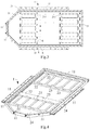
FIG. 1 is a stereogram of one embodiment of a battery tray of the application;
FIG. 2 is an exploded stereogram of the battery tray in FIG. 1;
FIG. 3 is a top view of the battery tray in FIG. 1;
FIG. 4 is an assembly stereogram of a frame structure, and an outer base plate, a reinforcing beam and a support beam of a base plate structure of the battery tray in FIG. 1;
FIG. 5 is an assembly stereogram of the frame structure and the base plate structure of the battery tray in FIG. 1;
FIG. 6 is an assembly stereogram of the frame structure, and the outer base plate and the reinforcing beam of the base plate structure of the battery tray in FIG. 1;
FIG. 7 is a partial stereogram of part A in FIG. 6, in which two frames in a state before assembly are illustrated;
FIG. 8 is a partial stereogram of the part A in FIG. 6, in which the two frames in a state after assembly are illustrated;
FIG. 9 is a partial stereogram of part B in FIG. 6, in which a frame, a reinforcing block and a reinforcing beam of the battery tray in a state before assembly are illustrated; and
FIG. 10 is a partial stereogram of the part B in FIG. 6, in which the frame, the reinforcing block and the reinforcing beam of the battery tray in a state after assembly are illustrated.
In the figures, the description of the reference numerals is as follows:
1 frame structure 24 outer base plate
11 frame 3 reinforcing block
111 first protrusion 31 first end
112A top surface 32 second end
112B bottom surface 33 first step portion
113 matching step 331 first groove
2 base plate structure 34A second upper step portion
21 inner base plate 341A second upper groove
211 inner recess 34B second lower step portion
22 reinforcing beam 341B second lower groove
221A second upper protrusion 35A top surface
221B second lower protrusion 35B bottom surface
222A top surface R rivet
222B bottom surface S bush
23 support beam
DESCRIPTION OF EMBODIMENTS
The accompanying drawings illustrate the embodiments of the application, it is to be understood that the disclosed embodiments are merely examples of the application that may be implemented in various forms, and therefore, the specific details disclosed herein should not be construed as limiting, but merely serve as a basis for the claims and as an indicative basis for teaching those of ordinary skill in the art to implement the application in various ways.
A battery tray of the application may be configured to accommodate a battery module.
The battery module (not shown) includes a plurality of batteries assembled together side by side. The battery may be a hard shell battery (or called as a tank type battery) or a soft package battery (or called as a bag type battery). The hard shell battery includes an electrode assembly, a housing, a top cover, poles, an injection hole, an explosion-proof valve and the like. An accommodating cavity is formed inside the housing, to accommodate the electrode assembly and an electrolyte. The electrode assembly includes a positive electrode plate, a negative electrode plate and a barrier isolating the positive electrode plate from the negative electrode plate. The electrode assembly can winding the positive electrode plate, the negative electrode plate and the barrier or stack the positive electrode plate, the negative electrode plate and the barrier. Each of the positive electrode plate and the negative electrode plate includes a current collector and an active substance layer arranged on the current collector. The soft package battery includes a packaging bag (for example, formed by an aluminum-plastic film), an electrode assembly (with the constitution and formation similar to those of the hard shell battery) and tabs. Parts of the tab is packaged in the packaging bag and the other part thereof extends out of the packaging bag. The tab may be directly formed by an electrode plate or uses an independent conductive material and is electrically connected to the current collector.
FIG. 1 is a stereogram of one embodiment of the battery tray of the application; FIG. 2 is an exploded stereogram of the battery tray in FIG. 1; FIG. 3 is a top view of the battery tray in FIG. 1; FIG. 4 is an assembly stereogram of a frame structure, and an outer base plate, a reinforcing beam and a support beam of a base plate structure of the battery tray in FIG. 1; FIG. 5 is an assembly stereogram of the frame structure and the base plate structure of the battery tray in FIG. 1; FIG. 6 is an assembly stereogram of the frame structure, and the outer base plate and the reinforcing beam of the base plate structure of the battery tray in FIG. 1; FIG. 7 is a partial stereogram of part A in FIG. 6, in which two frames in a state before assembly are illustrated; FIG. 8 is a partial stereogram of the part A in FIG. 6, in which the two frames in a state after assembly are illustrated; FIG. 9 is a partial stereogram of part B in FIG. 6, in which a frame, a reinforcing block and a reinforcing beam of the battery tray in a state before assembly are illustrated; and FIG. 10 is a partial stereogram of the part B in FIG. 6, in which the frame, the reinforcing block and the reinforcing beam of the battery tray in a state after assembly are illustrated.
The battery tray of the application includes the frame structure 1, the base plate structure 2 and the reinforcing block 3.
The frame structure 1 includes a plurality of frames 11 sequentially connected end to end arranged to be connected to a vehicle. In order to decrease a weight of the whole battery tray, the frame structure 1 is made of an aluminum profile, and the frame structure 1 may be of a hollow structure. In order to make an upper surface of the frame 11 flush with a lower surface thereof, refer to FIGS. 6-8, an end of the frame 11 may be provided with a matching step 113, and all the frames 11 match one another through the matching steps 113 at the ends. The matching steps 113 at the ends of all the frames 11 correspondingly match one another and are fixed together in a welding mode.
The base plate structure 2 includes an inner base plate 21 and the reinforcing beam 22. The base plate structure 2 further includes the support beam 23 and the outer base plate 24.
The inner base plate 21 is made of a steel sheet, an aluminum sheet and the like. In order to increase a space utilization rate, the inner base plate 21 is provided with a plurality of inner recesses 211 arranged to accommodate the battery module. The plurality of recesses 211 are formed by stamping the inner base plate 21. The inner base plate 21 is located on an inner side of the reinforcing beam 22 and arranged for mounting the battery module, and the inner base plate 21 is fixed inside the frame structure 1. The inner base plate 21 is fixed inside the frame structure 1 in a detachable connection mode (for example, riveting, gluing or threaded connection), so as to reduce the welding deformation caused by a welding fixation mode.
The reinforcing beam 22 is made of an aluminum profile, so as to guarantee a light weight, a high lightness degree and a low cost. The reinforcing beam 22 is fixed inside the frame structure 1. In order to enhance the strength, a plurality of reinforcing beams 22 are arranged.
If the inner base plate 21 needs to bear a force in the use process, in order to enhance the strength, the support beam 23 is connected between two adjacent reinforcing beams 22. The support beam 23 is made of an aluminum profile, so as to guarantee a light weight, a high lightness degree and a low cost. The number of the support beam/support beams 23 between two adjacent reinforcing beams 22 may be set to one or more on the basis of the strength requirement.
The outer base plate 24 is fixed inside the frame structure 1 and located on an outer side of the reinforcing beam 22. The outer base plate 24 is made of an aluminum sheet, a skin and the like. The outer base plate 24 is preferably the skin, so as to decrease a total weight. The outer base plate 24 is fixed inside the frame structure 1 in a detachable connection mode (for example, riveting, gluing or threaded connection), so as to reduce the welding deformation caused by a welding fixation mode. In the embodiments shown in the figures, the base plate structure 2 enhances, through the combination between the inner base plate 21 and the outer base plate 24, the structural strength, to cope with the situations of collision, impact and the like. The inner base plate 21 and the frame structure 1 are fixedly connected together by using rivets R, and bushes S are further used at some parts needing the fixation reinforcement to realize the interference fit between the inner base plate 21 and the frame structure 1, so as to reduce the wear. The outer base plate 24 and the frame structure 1 are fixedly connected together through gluing.
The reinforcing block 3 is made of an aluminum profile, so as to guarantee a light weight, a high lightness degree and a low cost. A first end 31 of the reinforcing block 3 is connected to a corresponding frame 11 in a matching mode, and a second end 32 of the reinforcing block 3 is connected to the reinforcing beam 22 in a matching mode, so as to fixedly connect the reinforcing beam 22 to the frame structure 1 through the reinforcing block 3. For one reinforcing beam 22, the number of the reinforcing blocks 3 may be two, first ends 31 of the two reinforcing blocks 3 are separately connected to corresponding frames 11 in a matching mode, and second ends 32 of the two reinforcing blocks 3 separately correspond to two ends of a reinforcing beam 22 and are connected to the same in a matching mode. The first end 31 of the reinforcing block 3 is arranged to be connected to the corresponding frame 11 through friction stir welding, and the second end 32 of the reinforcing block 3 is arranged to be connected to an end of the corresponding reinforcing beam 22 through friction stir welding. The friction stir welding process is low in thermal deformation, small in residual stress and high in welding quality. After friction stir welding, due to the characteristics of the welding process, difficult-to-distinguish solid joints are formed between the reinforcing block 3 and each of the corresponding frame 11 and the reinforcing beam 22, instead of what is shown in FIG. 10 that matching connection relations of various structures among the reinforcing block 3, the corresponding frame 11 and the reinforcing beam 22 can be clearly seen.
Particularly, take one reinforcing block 3 for the description, a first end 31 of the reinforcing block 3 is connected to a corresponding frame 11 in a concave-convex fit mode, so as to make positioning accurate and connection stable. The first end 31 of the reinforcing block 3 is provided with a first step portion 33, a first groove 331 is formed in the first step portion 33, and the corresponding frame 11 is provided with a first protrusion 111 matching the first groove 331. A second end 32 of the reinforcing block 3 is connected to an end of a reinforcing beam 22 in a concave-convex fit mode, so as to make positioning accurate and connection stable. The second end 32 of the reinforcing block 3 is provided with a second upper step portion 34A, a second upper groove 341A is formed in the second upper step portion 34A, and the end of the reinforcing beam 22 is provided with a second upper protrusion 221A matching the second upper groove 341A. The second end 32 of the reinforcing block 3 is further provided with a second lower step portion 34B, a second lower groove 341B is formed in the second lower step portion 34B, and the end of the reinforcing beam 22 is provided with a second lower protrusion 221B matching the second lower groove 341B. By means of this above-mentioned matching connection mode between the first groove 331 and the first protrusion 111, between the second upper groove 341A and the second upper protrusion 221A, and between the second lower groove 341B and the second lower protrusion 221B, positioning is accurate and connection is stable, thereby improving the overall strength of the battery tray.
In order to facilitate mounting, positioning and machining, a top surface 35A of the reinforcing block 3 is flush with a top surface 222A, provided with the second upper protrusion 221A, of the reinforcing beam 22, and the top surface 35A of the reinforcing block 3 is flush with a top surface 112A, provided with the first protrusion 111, of the frame 11; and a bottom surface 35B of the reinforcing block 3 is flush with a bottom surface 222B, provided with the second lower protrusion 221B, of the reinforcing beam 22, and the bottom surface 35B of the reinforcing block 3 is flush with a bottom surface 112B, provided with the first protrusion 111, of the frame 11.
In the battery tray of the application, it is not needed to process the frame structure 1 and the reinforcing beam 2 as in the background art, and since a size and a weight of the reinforcing block 3 are much smaller than those of the frame structure 1 and the reinforcing beam 2, compared with a mode that the frame structure 1 and the reinforcing beam 2 are thickened in the background art, the weight is decreased only by using the reinforcing block 3 to fixedly connect the reinforcing beam 22 to the frame structure 1; and therefore, compared with the background art, the strength of the battery tray is enhanced and the total weight is decreased, so as to prevent the strength enhancement and the weight decrease from becoming mutually-constrained factors as in the background art.
A vehicle of the application includes a battery tray and a battery module, wherein the battery module is mounted at the battery tray, a frame 11 of a frame structure 1 of the battery tray is connected to the vehicle, and an inner base plate 21 of a base plate structure 2 mounts the battery module.
The detailed description above describes a plurality of exemplary embodiments, but it is not intended to be limited to an explicitly disclosed combination herein. Hence, unless otherwise indicated, various features disclosed herein may be combined together to form a plurality of additional combinations which are not shown for an objective of simplicity.
What is said above is merely the preferred embodiments of the application, but is not used for limiting the application, and for a person skilled in the air, the application may have various alterations and changes. Any modifications, equivalent replacements, improvements and the like made within the spirit and principle of the application should all fall within the scope of protection of the application.

Claims (12)

What is claimed is:
1. A battery tray, comprising:
a frame structure, comprising a plurality of frames sequentially connected end to end, and arranged to be connected to a vehicle; and
a base plate structure, comprising an inner base plate and a reinforcing beam, the inner base plate being located on an inner side of the reinforcing beam and arranged for mounting a battery module, and the inner base plate and the reinforcing beam being fixed inside the frame structure; and
the battery tray further comprising:
a reinforcing block, a first end of the reinforcing block being connected to a corresponding frame in a matching mode, and a second end of the reinforcing block being connected to the reinforcing beam in a matching mode, so as to fixedly connect the reinforcing beam to the frame structure through the reinforcing block, wherein the first end of the reinforcing block is connected to the corresponding frame in a concave-convex fit mode.
2. The battery tray according to claim 1, wherein the first end of the reinforcing block is provided with a first step portion, a first groove is formed in the first step portion, and the corresponding frame is provided with a first protrusion matching the first groove.
3. The battery tray according to claim 2, wherein the top surface of the reinforcing block is flush with a top surface of the frame provided with the first protrusion.
4. The battery tray according to claim 2, wherein the bottom surface of the reinforcing block is flush with a bottom surface of the frame provided with the first protrusion.
5. The battery tray according to claim 1, wherein the second end of the reinforcing block is connected to an end of the reinforcing beam in a concave-convex fit mode.
6. The battery tray according to claim 5, wherein the second end of the reinforcing block is provided with a second upper step portion, a second upper groove is formed in the second upper step portion, and the end of the reinforcing beam is provided with a second upper protrusion matching the second upper groove.
7. The battery tray according to claim 6, wherein a top surface of the reinforcing block is flush with a top surface of the reinforcing beam provided with the second upper protrusion.
8. The battery tray according to claim 5, wherein the second end of the reinforcing block is further provided with a second lower step portion, a second lower groove is formed in the second lower step portion, and the end of the reinforcing beam is provided with a second lower protrusion matching the second lower groove.
9. The battery tray according to claim 8, wherein a bottom surface of the reinforcing block is flush with a bottom surface of the reinforcing beam provided with the second lower protrusion.
10. The battery tray according to claim 1, wherein the inner base plate is provided with a plurality of inner recesses arranged to accommodate the battery module.
11. The battery tray according to claim 1, wherein a plurality of reinforcing beams are arranged, the base plate structure further comprises a support beam connected between two adjacent reinforcing beams.
12. A vehicle, comprising a battery tray and a battery module, wherein the battery tray is the battery tray of claim 1, the battery tray is connected to the vehicle, and the battery module is mounted at the battery tray.
US17/133,594 2018-11-27 2020-12-23 Battery tray and vehicle Active US11148520B2 (en)

Priority Applications (2)

Application Number Priority Date Filing Date Title
US17/462,727 US11548365B2 (en) 2018-11-27 2021-08-31 Battery tray and vehicle
US17/462,827 US11554654B2 (en) 2018-11-27 2021-08-31 Battery tray and vehicle

Applications Claiming Priority (3)

Application Number Priority Date Filing Date Title
CN201821967959.2 2018-11-27
CN201821967959.2U CN209176495U (en) 2018-11-27 2018-11-27 Battery tray
PCT/CN2019/114038 WO2020108209A1 (en) 2018-11-27 2019-10-29 Battery tray and vehicle

Related Parent Applications (1)

Application Number Title Priority Date Filing Date
PCT/CN2019/114038 Continuation WO2020108209A1 (en) 2018-11-27 2019-10-29 Battery tray and vehicle

Related Child Applications (2)

Application Number Title Priority Date Filing Date
US17/462,827 Continuation US11554654B2 (en) 2018-11-27 2021-08-31 Battery tray and vehicle
US17/462,727 Continuation US11548365B2 (en) 2018-11-27 2021-08-31 Battery tray and vehicle

Publications (2)

Publication Number Publication Date
US20210114449A1 US20210114449A1 (en) 2021-04-22
US11148520B2 true US11148520B2 (en) 2021-10-19

Family

ID=67374313

Family Applications (3)

Application Number Title Priority Date Filing Date
US17/133,594 Active US11148520B2 (en) 2018-11-27 2020-12-23 Battery tray and vehicle
US17/462,827 Active 2039-11-12 US11554654B2 (en) 2018-11-27 2021-08-31 Battery tray and vehicle
US17/462,727 Active 2039-11-08 US11548365B2 (en) 2018-11-27 2021-08-31 Battery tray and vehicle

Family Applications After (2)

Application Number Title Priority Date Filing Date
US17/462,827 Active 2039-11-12 US11554654B2 (en) 2018-11-27 2021-08-31 Battery tray and vehicle
US17/462,727 Active 2039-11-08 US11548365B2 (en) 2018-11-27 2021-08-31 Battery tray and vehicle

Country Status (4)

Country Link
US (3) US11148520B2 (en)
EP (1) EP3795399B1 (en)
CN (1) CN209176495U (en)
WO (1) WO2020108209A1 (en)

Families Citing this family (12)

* Cited by examiner, † Cited by third party
Publication number Priority date Publication date Assignee Title
CN209176495U (en) 2018-11-27 2019-07-30 宁德时代新能源科技股份有限公司 Battery tray
CN210467906U (en) 2019-07-03 2020-05-05 江苏时代新能源科技有限公司 Battery lower box body and battery system
CN110611064A (en) * 2019-09-29 2019-12-24 江苏大学 Aluminum alloy battery pack lower shell
CN110977337B (en) * 2019-11-19 2022-07-26 江苏铭智新能源汽车零部件有限公司 Production method of battery tray for new energy electric automobile
CN113001102A (en) * 2019-12-20 2021-06-22 江苏亚太霍夫曼金属打印科技有限公司 New energy automobile battery tray frame punching method
US11685502B2 (en) * 2020-06-30 2023-06-27 Textron Innovations Inc. Modular hybrid airframe structure for battery thermal event protection and repair
CN112563650B (en) * 2020-12-09 2023-04-11 深圳市衡亿安科技有限公司 A location complementary unit that is used for new energy automobile to produce with equipment
CN115595526A (en) * 2021-07-09 2023-01-13 东莞令特电子有限公司(Cn) Height adjustable mask tray assembly for arc spray application
JP2023131342A (en) * 2022-03-09 2023-09-22 株式会社神戸製鋼所 Battery case for electric vehicle and manufacturing method for the same
CN114792864A (en) * 2022-05-31 2022-07-26 东风汽车集团股份有限公司 Lower box structure of battery pack
CN115000609A (en) * 2022-07-12 2022-09-02 一汽解放汽车有限公司 Battery fixing device and vehicle
CN115275484B (en) * 2022-07-14 2024-03-12 江苏天钧精密技术有限公司 Lightweight CTP battery tray

Citations (11)

* Cited by examiner, † Cited by third party
Publication number Priority date Publication date Assignee Title
JP2013256265A (en) 2012-06-14 2013-12-26 Toyota Motor Corp Vehicular battery mounting structure
WO2015083487A1 (en) 2013-12-02 2015-06-11 トヨタ自動車株式会社 Vehicle battery mounting structure
US20170036524A1 (en) 2013-12-25 2017-02-09 Toyota Jidosha Kabushiki Kaisha Vehicle panel structure
US20170087972A1 (en) 2015-09-30 2017-03-30 Fuji Jukogyo Kabushiki Kaisha Vehicle body structure and onboard battery for vehicle
CN206584986U (en) 2017-03-23 2017-10-24 宁德时代新能源科技股份有限公司 Battery bag shielded frame and battery bag
CN107851753A (en) 2015-07-30 2018-03-27 三洋电机株式会社 Supply unit and the vehicle using the supply unit
DE102016121252A1 (en) 2016-11-07 2018-05-09 Benteler Automobiltechnik Gmbh Battery carrier with corner connector and method for producing a battery carrier
US20180272853A1 (en) 2017-03-23 2018-09-27 Contemporary Amperex Technology Co., Limited Battery pack protective frame and battery pack
DE102017106648A1 (en) 2017-03-28 2018-10-04 Volkswagen Aktiengesellschaft Securing frame for a battery receiving system
US20190100090A1 (en) * 2017-10-04 2019-04-04 Shape Corp. Battery tray floor assembly for electric vehicles
CN209176495U (en) 2018-11-27 2019-07-30 宁德时代新能源科技股份有限公司 Battery tray

Patent Citations (14)

* Cited by examiner, † Cited by third party
Publication number Priority date Publication date Assignee Title
JP2013256265A (en) 2012-06-14 2013-12-26 Toyota Motor Corp Vehicular battery mounting structure
WO2015083487A1 (en) 2013-12-02 2015-06-11 トヨタ自動車株式会社 Vehicle battery mounting structure
US20160288636A1 (en) 2013-12-02 2016-10-06 Toyota Jidosha Kabushiki Kaisha Vehicle battery mounting structure
US20170036524A1 (en) 2013-12-25 2017-02-09 Toyota Jidosha Kabushiki Kaisha Vehicle panel structure
US20180138473A1 (en) 2015-07-30 2018-05-17 Sanyo Electric Co., Ltd. Power supply device and vehicle using same
CN107851753A (en) 2015-07-30 2018-03-27 三洋电机株式会社 Supply unit and the vehicle using the supply unit
CN106553515A (en) 2015-09-30 2017-04-05 富士重工业株式会社 Body structure and vehicle battery
US20170087972A1 (en) 2015-09-30 2017-03-30 Fuji Jukogyo Kabushiki Kaisha Vehicle body structure and onboard battery for vehicle
DE102016121252A1 (en) 2016-11-07 2018-05-09 Benteler Automobiltechnik Gmbh Battery carrier with corner connector and method for producing a battery carrier
CN206584986U (en) 2017-03-23 2017-10-24 宁德时代新能源科技股份有限公司 Battery bag shielded frame and battery bag
US20180272853A1 (en) 2017-03-23 2018-09-27 Contemporary Amperex Technology Co., Limited Battery pack protective frame and battery pack
DE102017106648A1 (en) 2017-03-28 2018-10-04 Volkswagen Aktiengesellschaft Securing frame for a battery receiving system
US20190100090A1 (en) * 2017-10-04 2019-04-04 Shape Corp. Battery tray floor assembly for electric vehicles
CN209176495U (en) 2018-11-27 2019-07-30 宁德时代新能源科技股份有限公司 Battery tray

Also Published As

Publication number Publication date
EP3795399A4 (en) 2021-06-16
CN209176495U (en) 2019-07-30
US20210394603A1 (en) 2021-12-23
EP3795399A1 (en) 2021-03-24
WO2020108209A1 (en) 2020-06-04
US11548365B2 (en) 2023-01-10
US20210114449A1 (en) 2021-04-22
EP3795399B1 (en) 2021-12-15
US11554654B2 (en) 2023-01-17
US20210394604A1 (en) 2021-12-23

Similar Documents

Publication Publication Date Title
US11148520B2 (en) Battery tray and vehicle
KR102475839B1 (en) Rechargeable battery module
US8846238B2 (en) Battery module
US20190006646A1 (en) Battery pack
US11114726B2 (en) Battery box
WO2020135005A1 (en) Battery pack and vehicle
US20120214046A1 (en) Battery module
US10826047B2 (en) Rechargeable battery
US6127064A (en) Jar can for secondary battery
US11362393B2 (en) Battery pack
US20210119279A1 (en) Battery box
EP2450979B1 (en) Battery module
JP2020129527A (en) Binding member
US11329347B2 (en) Battery pack and vehicle
CN216818520U (en) Battery package box, battery package and electric automobile
US20070012497A1 (en) Support structure of power supply system
KR20070014630A (en) Secondary battery module
CN112332007B (en) Battery module, battery pack, vehicle, and method for assembling battery module
CN214378641U (en) Battery cover plate structure and battery
US11784380B2 (en) Battery module
CN216818519U (en) Battery pack box and battery pack
CN217672832U (en) Lower automobile body subassembly and vehicle
JP2003249200A (en) Storage battery
EP3886199A1 (en) Battery pack
JP2004139822A (en) Battery

Legal Events

Date Code Title Description
AS Assignment

Owner name: CONTEMPORARY AMPEREX TECHNOLOGY CO., LIMITED, CHINA

Free format text: ASSIGNMENT OF ASSIGNORS INTEREST;ASSIGNORS:CHU, YANNAN;JI, JINQING;QIAN, MU;AND OTHERS;SIGNING DATES FROM 20201127 TO 20201130;REEL/FRAME:054745/0326

FEPP Fee payment procedure

Free format text: ENTITY STATUS SET TO UNDISCOUNTED (ORIGINAL EVENT CODE: BIG.); ENTITY STATUS OF PATENT OWNER: LARGE ENTITY

STPP Information on status: patent application and granting procedure in general

Free format text: DOCKETED NEW CASE - READY FOR EXAMINATION

STPP Information on status: patent application and granting procedure in general

Free format text: NON FINAL ACTION MAILED

STPP Information on status: patent application and granting procedure in general

Free format text: RESPONSE TO NON-FINAL OFFICE ACTION ENTERED AND FORWARDED TO EXAMINER

STPP Information on status: patent application and granting procedure in general

Free format text: NOTICE OF ALLOWANCE MAILED -- APPLICATION RECEIVED IN OFFICE OF PUBLICATIONS

STPP Information on status: patent application and granting procedure in general

Free format text: AWAITING TC RESP., ISSUE FEE NOT PAID

STPP Information on status: patent application and granting procedure in general

Free format text: NOTICE OF ALLOWANCE MAILED -- APPLICATION RECEIVED IN OFFICE OF PUBLICATIONS

STPP Information on status: patent application and granting procedure in general

Free format text: PUBLICATIONS -- ISSUE FEE PAYMENT RECEIVED

STPP Information on status: patent application and granting procedure in general

Free format text: PUBLICATIONS -- ISSUE FEE PAYMENT VERIFIED

STCF Information on status: patent grant

Free format text: PATENTED CASE