WO2015076141A1 - 浮上搬送装置 - Google Patents
浮上搬送装置 Download PDFInfo
- Publication number
- WO2015076141A1 WO2015076141A1 PCT/JP2014/079776 JP2014079776W WO2015076141A1 WO 2015076141 A1 WO2015076141 A1 WO 2015076141A1 JP 2014079776 W JP2014079776 W JP 2014079776W WO 2015076141 A1 WO2015076141 A1 WO 2015076141A1
- Authority
- WO
- WIPO (PCT)
- Prior art keywords
- negative pressure
- transport
- conveyance
- port
- pressure generating
- Prior art date
- Legal status (The legal status is an assumption and is not a legal conclusion. Google has not performed a legal analysis and makes no representation as to the accuracy of the status listed.)
- Ceased
Links
Images

Classifications
-
- H—ELECTRICITY
- H10—SEMICONDUCTOR DEVICES; ELECTRIC SOLID-STATE DEVICES NOT OTHERWISE PROVIDED FOR
- H10P—GENERIC PROCESSES OR APPARATUS FOR THE MANUFACTURE OR TREATMENT OF DEVICES COVERED BY CLASS H10
- H10P72/00—Handling or holding of wafers, substrates or devices during manufacture or treatment thereof
- H10P72/30—Handling or holding of wafers, substrates or devices during manufacture or treatment thereof for conveying, e.g. between different workstations
- H10P72/32—Handling or holding of wafers, substrates or devices during manufacture or treatment thereof for conveying, e.g. between different workstations between different workstations
- H10P72/3202—Mechanical details, e.g. rollers or belts
-
- B—PERFORMING OPERATIONS; TRANSPORTING
- B65—CONVEYING; PACKING; STORING; HANDLING THIN OR FILAMENTARY MATERIAL
- B65G—TRANSPORT OR STORAGE DEVICES, e.g. CONVEYORS FOR LOADING OR TIPPING, SHOP CONVEYOR SYSTEMS OR PNEUMATIC TUBE CONVEYORS
- B65G13/00—Roller-ways
- B65G13/02—Roller-ways having driven rollers
- B65G13/04—Roller-ways having driven rollers all rollers driven
-
- B—PERFORMING OPERATIONS; TRANSPORTING
- B65—CONVEYING; PACKING; STORING; HANDLING THIN OR FILAMENTARY MATERIAL
- B65G—TRANSPORT OR STORAGE DEVICES, e.g. CONVEYORS FOR LOADING OR TIPPING, SHOP CONVEYOR SYSTEMS OR PNEUMATIC TUBE CONVEYORS
- B65G49/00—Conveying systems characterised by their application for specified purposes not otherwise provided for
- B65G49/05—Conveying systems characterised by their application for specified purposes not otherwise provided for for fragile or damageable materials or articles
- B65G49/06—Conveying systems characterised by their application for specified purposes not otherwise provided for for fragile or damageable materials or articles for fragile sheets, e.g. glass
- B65G49/061—Lifting, gripping, or carrying means, for one or more sheets forming independent means of transport, e.g. suction cups, transport frames
-
- B—PERFORMING OPERATIONS; TRANSPORTING
- B65—CONVEYING; PACKING; STORING; HANDLING THIN OR FILAMENTARY MATERIAL
- B65G—TRANSPORT OR STORAGE DEVICES, e.g. CONVEYORS FOR LOADING OR TIPPING, SHOP CONVEYOR SYSTEMS OR PNEUMATIC TUBE CONVEYORS
- B65G49/00—Conveying systems characterised by their application for specified purposes not otherwise provided for
- B65G49/05—Conveying systems characterised by their application for specified purposes not otherwise provided for for fragile or damageable materials or articles
- B65G49/06—Conveying systems characterised by their application for specified purposes not otherwise provided for for fragile or damageable materials or articles for fragile sheets, e.g. glass
- B65G49/063—Transporting devices for sheet glass
- B65G49/064—Transporting devices for sheet glass in a horizontal position
- B65G49/065—Transporting devices for sheet glass in a horizontal position supported partially or completely on fluid cushions, e.g. a gas cushion
-
- B—PERFORMING OPERATIONS; TRANSPORTING
- B65—CONVEYING; PACKING; STORING; HANDLING THIN OR FILAMENTARY MATERIAL
- B65G—TRANSPORT OR STORAGE DEVICES, e.g. CONVEYORS FOR LOADING OR TIPPING, SHOP CONVEYOR SYSTEMS OR PNEUMATIC TUBE CONVEYORS
- B65G51/00—Conveying articles through pipes or tubes by fluid flow or pressure; Conveying articles over a flat surface, e.g. the base of a trough, by jets located in the surface
- B65G51/02—Directly conveying the articles, e.g. slips, sheets, stockings, containers or workpieces, by flowing gases
- B65G51/03—Directly conveying the articles, e.g. slips, sheets, stockings, containers or workpieces, by flowing gases over a flat surface or in troughs
-
- H—ELECTRICITY
- H10—SEMICONDUCTOR DEVICES; ELECTRIC SOLID-STATE DEVICES NOT OTHERWISE PROVIDED FOR
- H10P—GENERIC PROCESSES OR APPARATUS FOR THE MANUFACTURE OR TREATMENT OF DEVICES COVERED BY CLASS H10
- H10P72/00—Handling or holding of wafers, substrates or devices during manufacture or treatment thereof
- H10P72/30—Handling or holding of wafers, substrates or devices during manufacture or treatment thereof for conveying, e.g. between different workstations
- H10P72/36—Handling or holding of wafers, substrates or devices during manufacture or treatment thereof for conveying, e.g. between different workstations using air tracks
-
- B—PERFORMING OPERATIONS; TRANSPORTING
- B65—CONVEYING; PACKING; STORING; HANDLING THIN OR FILAMENTARY MATERIAL
- B65G—TRANSPORT OR STORAGE DEVICES, e.g. CONVEYORS FOR LOADING OR TIPPING, SHOP CONVEYOR SYSTEMS OR PNEUMATIC TUBE CONVEYORS
- B65G2249/00—Aspects relating to conveying systems for the manufacture of fragile sheets
- B65G2249/04—Arrangements of vacuum systems or suction cups
- B65G2249/045—Details of suction cups suction cups
Definitions
- the present invention relates to a levitation conveyance device that conveys a conveyed product in a conveyance direction by a driving force of a rolling element such as a conveyance roller while levitating from a conveyance surface, and in particular, a collision with a rolling element and a conveyance surface to be conveyed.
- the present invention relates to a levitation transport device that can efficiently transmit the driving force of a rolling element to a transport target while preventing it.
- a levitation conveyance device described in Patent Document 1 is known as a device that conveys a substrate with a driving force of a conveyance roller while floating from a conveyance surface.
- a plurality of levitation units for ejecting compressed gas for levitating the substrate are arranged on the conveyance surface of the levitation conveyance apparatus in the conveyance direction and the conveyance width direction (direction orthogonal to the conveyance direction).
- a plurality of roller drive units are arranged along the transport direction between the floating unit rows arranged in the transport direction to transport the substrate that has floated from the transport surface in the transport direction by the ejection of compressed gas from the float unit. ing.
- Each roller drive unit sucks air from inside the unit case, a conveyance roller that conveys the substrate in the conveyance direction, a motor, a belt mechanism that transmits the rotation of the motor to the conveyance roller, a unit case that accommodates these, And a suction fan.
- An opening is formed on the upper surface of the unit case, and the outer periphery of the transport roller protrudes upward (substrate side) from the upper surface of the unit case through this opening, and supports the back surface of the substrate that has floated from the transport surface.
- a negative pressure region is formed inside the unit case by the operation of the suction motor, the substrate floating from the transport surface is drawn toward the unit case.
- the back surface of the substrate and the outer peripheral surface of the transport roller are brought into close contact with each other. Therefore, when the transport roller is rotated by the operation of the motor, the driving force of the transport roller is efficiently transmitted to the substrate, and the substrate floats from the transport surface. It is efficiently transported in the transport direction.
- the substrate being transported enters the opening of the unit case of the roller drive unit, it is immediately drawn to the negative pressure region in the unit case. For this reason, for example, if the air inside the unit case is sucked too much by the suction fan, the front end of the substrate being transported is positioned lower than the height of the transport roller protruding from the upper surface of the unit case before it gets on the transport roller. May be drawn to the unit case side and collide with the conveyance surface or the conveyance roller.
- the present invention has been made in view of the above circumstances, and a first object thereof is to efficiently make the driving force of the rolling element to be conveyed while preventing collision of the rolling object with the rolling element and the conveying surface.
- An object of the present invention is to provide a levitation transfer device capable of transmission.
- a second object is to provide such a levitation transport apparatus at a low cost.
- the conveyance target is drawn toward the conveyance surface.
- one embodiment of the present invention provides: A levitation transport device that transports in a transport direction while levitating a transport target, An air plate having a conveying surface formed with a plurality of jet nozzles for ejecting compressed gas that floats the rolling object accommodation port and the conveyance object; The outer peripheral surface is arranged to protrude from the transfer surface to the transfer target side from the rolling element housing port, and the outer peripheral surface is brought into contact with the transfer target that has floated from the transfer surface due to the ejection of the compressed gas from the jet port.
- a rolling element that rotates while moving the transfer object in the transfer direction There are negative pressure generation ports that open on the transfer surface on both sides of the rolling element accommodation port with respect to the transfer direction, and the negative pressure that draws the transfer object that has floated from the transfer surface toward the transfer surface is negative.
- Negative pressure generating means generated by the pressure generating port The outer peripheral surface of the rolling element protrudes most from the conveyance surface in a region perpendicular to the conveyance direction, which is sandwiched between negative pressure generation ports that the negative pressure generating means has on both sides of the rolling element accommodation port. .
- a levitation transport device that transports in a transport direction while levitating a transport target,
- An air plate having a conveying surface formed with a plurality of jet nozzles for ejecting compressed gas that floats the rolling object accommodation port and the conveyance object;
- the outer peripheral surface is arranged to protrude from the transfer surface to the transfer target side from the rolling element housing port, and the outer peripheral surface is brought into contact with the transfer target that has floated from the transfer surface due to the ejection of the compressed gas from the jet port.
- Negative pressure generating means that has a negative pressure generating port that opens on the transfer surface, and generates a negative pressure that draws the transfer object that has floated from the transfer surface toward the transfer surface side, by the negative pressure generating port.
- the negative pressure generating port is disposed in a region on one side of the rolling element accommodation port with respect to the conveying direction, and an outer peripheral surface of the rolling element is a distance from an axis of the negative pressure generating port. In the region where the component in the transport direction is less than the radius of the negative pressure generating port.
- Still another aspect of the present invention provides: A levitation transport device that transports in a transport direction while levitating a transport target, An air plate having a conveying surface formed with a plurality of jet nozzles for ejecting compressed gas that floats the rolling object accommodation port and the conveyance object; The outer peripheral surface is arranged to protrude from the transfer surface to the transfer target side from the rolling element housing port, and the outer peripheral surface is brought into contact with the transfer target that has floated from the transfer surface due to the ejection of the compressed gas from the jet port.
- Negative pressure generating means that has a negative pressure generating port that opens on the transfer surface, and generates a negative pressure that draws the transfer object that has floated from the transfer surface toward the transfer surface side, by the negative pressure generating port.
- the negative pressure generating port is When viewed from above the conveying surface, the opening of the negative pressure generating port and the straight line passing through the position where the outer peripheral surface of the rolling element protrudes most from the conveying surface in a direction perpendicular to the conveying direction intersects. It is arranged at the position to do.
- Still another aspect of the present invention provides: A levitation conveyance device that levitates and conveys an object to be conveyed, An air plate having a conveying surface on which a plurality of jetting ports for ejecting compressed gas for levitation of the rolling element housing port and the conveying object are formed; The outer peripheral surface is arranged to protrude from the transfer surface to the transfer target side from the rolling element housing port, and the outer peripheral surface is brought into contact with the transfer target that has floated from the transfer surface due to the ejection of the compressed gas from the jet port.
- Negative pressure generating means for generating a negative pressure that draws the object to be conveyed floating from the conveying surface toward the conveying surface;
- the negative pressure generating means is arranged on the moving direction side of the object to be conveyed by the rolling element rather than the position where the outer peripheral surface of the rolling element protrudes most from the conveying surface.
- the negative pressure generating means has a cylindrical recess opening on the transport surface as the negative pressure generating port, and generates a swirling flow of gas by jetting compressed gas into the cylindrical recess to generate the negative pressure. It may generate pressure.
- a ventilation path that is connected to the plurality of jet outlets, and compressed gas that is jetted from the plurality of jet outlets is supplied from a compressed gas supply source.
- the cylindrical recess may be connected to the ventilation path, and the swirl flow may be formed by compressed air supplied from the compressed gas supply source via the ventilation path.
- the conveyance target that has floated from the conveyance surface is drawn toward the conveyance surface side by negative pressure after its front end surface passes through the position where the rolling element protrudes most from the conveyance surface. For this reason, while preventing collision between the rolling element and the conveyance surface and the conveyance object, the back surface of the conveyance object and the outer peripheral surface of the rolling element are reliably brought into contact with each other with appropriate pressure, and the driving force of the rolling element is efficiently conveyed. Can be communicated to the subject. Further, if a swirl flow that generates a negative pressure that draws the conveyance target that has floated from the conveyance surface is generated by jetting compressed gas, the compressed gas and the supply source for floating the conveyance target from the conveyance surface can be shared. . In this case, since it is not necessary to separately provide a device such as a suction fan or a suction pump for generating negative pressure, the manufacturing cost of the levitation transport device can be reduced.
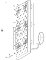
- FIG. 1 is a schematic configuration diagram of a levitation transport apparatus 1 according to an embodiment of the present invention.
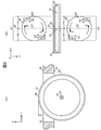
- FIG. 2A is an enlarged view of the AA cross-section of the conveyance roller accommodation port forming portion of FIG. 1
- FIG. 2B is a diagram showing the relationship between the conveyance roller 50 and the swirl flow generating unit 44 in the conveyance surface 40. It is a figure for demonstrating positional relationship.
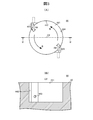
- 3A is an enlarged view of a portion where the swirling flow generating portion 44 is formed on the conveying surface 40 of the air plate 4
- FIG. 3B is a cross-sectional view of the swirling flow generating portion 44 taken along the line BB. is there.
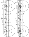
- FIG. 4 is a diagram for explaining a floating state of the conveyance target 9 conveyed by the levitation conveyance apparatus 1 according to the embodiment of the present invention.
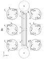
- FIG. 5 is an enlarged view of a portion where the swirl flow generating portion 44 is formed on the conveying surface 40 of the air plate 4 according to another embodiment of the present invention.
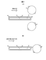
- FIGS. 6A and 6B are diagrams for explaining another example of the positional relationship between the conveyance roller 50 and the swirl flow generating unit 44 in the conveyance surface 40.
- FIGS. 7A and 7B are diagrams for explaining an example of the positional relationship between the transport roller 50 and the swirl flow generating unit 44 in the transport surface 40 when the transport target 9 is transported in one direction.
- FIG. 1 is a schematic configuration diagram of a levitation transport apparatus 1 according to the present embodiment
- FIG. 2A is an enlarged view of a cross section taken along the line AA of the transport roller accommodation port forming portion of FIG.
- a coordinate system having a Y axis along the transport direction, a Z axis along the vertical direction, an X axis perpendicular to the Z axis and the Y axis is defined. In other drawings, this coordinate system is used as appropriate.
- the levitating and conveying apparatus 1 for example, a sheet-like conveying object 9 such as a large glass substrate used in a flat display panel such as a liquid crystal display panel and a plasma display panel, for example, compressed air.
- the compressed air A1 (see FIG. 4) or the like is ejected from the conveying surface 40 while being jetted, and the conveying line 2 that conveys in one direction or both directions in the Y-axis direction and the compressed air A1 that causes the object 9 to be conveyed are conveyed.
- a pump 3 for supplying to the line 2.
- the transport line 2 includes a plurality of transports that transport the air plate 4 having a transport surface 40 arranged in the XY plane, and a transport target 9 that has floated from the transport surface 40 of the air plate 4 in the Y-axis direction (one direction or both directions). It is constructed by a roller transport mechanism 5 or the like constituted by a roller 50 or the like.
- FIG. 1 illustrates the case where one air plate 4 is used, but the number of air plates 4 corresponding to the transport distance of the transport object 9 are arranged in a line along the Y-axis direction,
- the rows of the air plates 4 may be arranged in a plurality of rows in the X-axis direction according to the width W of the conveyance target 9 in the X-axis direction.
- an air passage 46 connected to an air supply port (not shown) to which the air supply hose 30 of the pump 3 is connected is formed inside the air plate 4.
- An exhaust port 42 for exhausting the air A1 from the conveying surface 40 side of the air plate 4 to the back surface (surface opposite to the conveying surface 40) 47 side is formed in a predetermined layout (see FIG. 4).
- FIG. 1 for simplification, only a part of the ejection ports 41 and a part of the exhaust ports 42 are denoted by reference numerals.
- the compressed gas A3 is transferred from the ejection port 41 through the air supply port and the air passage 46 to the back surface (conveyance surface) of the conveyance target 9 on the conveyance surface 40 of the air plate 4.
- (Surface facing 40) is ejected as compressed gas A1 toward 90, passes between the transport surface 40 and the back surface 90 of the transport object 9, and is discharged from the exhaust port 42 as exhaust gas A2 (see FIG. 4).
- a compressed gas layer is formed between the back surface 90 of the conveyance target 9 and the conveyance surface 40, and the conveyance target 9 floats from the conveyance surface 40.
- the form of restriction of the jet nozzle 41 is not particularly limited, and may be a self-contained restriction, an orifice restriction, or a porous restriction.
- a plurality of slot-like through holes 43 along the Y-axis direction are formed on the conveyance surface 40 of the air plate 4 as the conveyance roller accommodation port 43 into which the conveyance roller 50 of the roller conveyance mechanism 5 is inserted.
- the roller accommodating ports 43 are arranged in a line along the Y-axis direction at intervals that are narrower than the width L of the conveyance target 9.
- the roller conveyance mechanism 5 includes a plurality of conveyance rollers 50 having a rotation shaft 52 arranged along the X-axis direction, a rotation shaft support member (not shown) that rotatably holds the rotation shaft 52 of the conveyance roller 50, and conveyance A motor (not shown) that rotates the roller 50, and is installed on the back surface 47 side of the air plate 4.
- the conveyance rollers 50 are inserted one by one from the back surface 47 side of the air plate 4 into the conveyance roller accommodation port 43, and the outer peripheral surface 51 of the conveyance roller 50 is set to the flying height of the conveyance object 9 from the conveyance surface 40 of the air plate 4. It protrudes in the Z-axis direction by a predetermined distance D.
- the outer peripheral surface 51 of the conveying roller 50 is a position that protrudes most in the Z-axis direction from the conveying surface 40 of the air plate 4 (a position where the circumferential tangent of the outer peripheral surface 51 of the conveying roller 50 faces in the Y-axis direction: 53) is arranged so as to come into contact with the back surface 90 of the conveyance target 9 that has floated from the conveyance surface 40 due to the ejection of the compressed gas A1 from the ejection port 41 and the exhaust of the exhaust gas A2 from the exhaust port 42. .
- the transport roller 50 rotates around the X axis while supporting the back surface 90 of the transport target 9 floating from the transport surface 40 with the top 53 of the outer peripheral surface 51 of the transport roller 50. Move along the Y-axis direction.
- FIG. 2B is a view for explaining the positional relationship between the transport roller 50 and the swirl flow generating unit 44 in the transport surface 40 of the air plate 4.
- 3A is an enlarged view of a portion where the swirling flow generating portion 44 is formed in the conveying surface 40 of the air plate 4, and
- FIG. 3B is a cross-sectional view taken along the line BB of the swirling flow generating portion 44.
- the swirl flow generation unit 44 includes a cylindrical recess (hereinafter referred to as a cylindrical chamber) 441 that opens in a circular shape toward the conveying surface 40 of the air plate 4 as a negative pressure generation port, and a cylindrical chamber 441.
- a cylindrical recess hereinafter referred to as a cylindrical chamber
- One or more swirling flow compressed gas jets 443 for jetting the compressed gas A4 in the circumferential tangential direction of the inner peripheral surface 442 are formed in the inside.
- the compressed gas jet port 443 for the swirling flow is connected to the vent passage 46 connected to the jet port 41, and the compressed gas A3 supplied from the pump 3 to the vent passage 46 is not only the jet port 41 but also the compressed gas jet port for the swirling flow. It spouts from 443.
- the compressed gas A4 is ejected from the swirling flow compressed gas outlet 443 in the circumferential tangential direction of the inner peripheral surface 442 of the cylindrical chamber 441, and the cylindrical chamber While flowing along the circumferential direction of the inner peripheral surface 442 of 441, it flows out from the opening 444 at the upper part of the cylindrical chamber 441 toward the back surface 90 of the transfer target 9 on the transfer surface 40 of the air plate 4.
- a gas swirl B is formed by such a gas flow.
- Two such swirl flow generating units 44 are arranged for each conveyance roller accommodation port 43.
- the cylindrical chambers 441 of the two swirling flow generation units 44 are arranged along the X-axis direction with the conveyance roller 50 interposed therebetween, and the conveyance roller 50 inserted into the conveyance roller accommodation port 43 has the rotation shaft 52 as the X-axis. It is positioned between these two cylindrical chambers 441 in a posture oriented in the direction.
- the axis O1 of the rotation shaft 52 of the transport roller 50 is a region in which the Y-axis direction component of the distance from the axis O2 of each of the two cylindrical chambers 441 is less than the radius R of the cylindrical chamber 441 (one cylindrical chamber).
- the cylindrical chamber 441 is positioned in a region overlapping the belt-like region C2 in the X-axis direction from the upstream position to the downstream position, which is separated from the radius R.
- the axis O1 of the rotation shaft 52 of the transport roller 50 is disposed in a region sandwiched between the two cylindrical chambers 441 (a region where the two belt-shaped regions C1 and C2 overlap). Yes.
- the two cylindrical chambers 441 are positioned on both sides of the transport roller 50 with respect to the Y-axis direction, and the top 53 of the outer peripheral surface 52 of the transport roller 50 is the two cylinders. It is arranged in a region sandwiched between the chambers 441 (a region where the two belt-like regions C1 and C2 overlap).
- the two cylindrical chambers 441 pass through the axis O2 of each cylindrical chamber 441 and the top 53 of the outer peripheral surface 51 of the transport roller 50 when viewed from the transport surface 40.
- an extension line of the axis O1 of the rotation shaft 52 of the conveyance roller 50 has been placed.
- the two swirl flow generation units 44 positioned on both sides in the X-axis direction with the conveyance roller 50 interposed therebetween.
- a negative pressure is generated in the central portion of the gas swirl B generated in the cylindrical chamber 441 (near the axis O2 of the cylindrical chamber 441). Therefore, as shown below, it is possible to smoothly place the conveyance target 9 on the top 53 of the outer peripheral surface 51 of the conveyance roller 50 without causing the front end surface 91 of the conveyance target 9 to collide with the conveyance roller 50.
- the driving force of the transport roller 50 can be efficiently transmitted to the transport target 9.
- FIG. 4 is a diagram for explaining a floating state of the conveyance target 9 conveyed by the levitation conveyance apparatus 1.
- 4A conceptually shows a state before the front end portion 92 of the conveyance target 9 gets on the next conveyance roller 50 in the front in the conveyance direction
- FIG. 4B shows the conveyance target.
- 9 schematically shows a state in which the front end portion 92 of 9 is on the next transport roller 50 in the front in the transport direction.
- the conveyance target 9 is at least one of the conveyance rollers 50 that are rotationally driven by the motor while being lifted from the conveyance surface 40 of the air plate 4 by the ejection of the compressed gas A1 from the plurality of ejection ports 41. It is transported in the Y-axis direction by contact between the outer peripheral surface 51 and the back surface 90 of the transport target 9. As shown in FIG.
- the transport target 9 Even if the front end surface 91 of the transport target 9 being transported reaches the top 53 of the outer peripheral surface 51 of the next transport roller 50 in front of the transport direction, the transport target 9 Does not cover the entire opening 444 of the upper part of the cylindrical chamber 441 of the swirl flow generation unit 44, so that the front end portion 92 of the conveyance target 9 is kept floating from the outer peripheral surface 51 of the conveyance roller 50.
- the front end surface 91 of the transport object 9 is positioned on both sides in the X-axis direction of the next transport roller 50 in front of the transport direction.
- the two swirl flow generators 44 enter the cylindrical chamber 441.
- the conveying target 9 has two swirl flow generating portions located on both sides in the X-axis direction of the conveying roller 50 after the front end surface 91 passes over the top 53 of the outer peripheral surface 51 of the conveying roller 50.
- the entire opening 444 of the upper part of the 44 cylindrical chambers 441 is covered.
- each swirl flow is generated.
- the vicinity of the axial center O2 of the cylindrical chamber 441 of the generating unit 44 (the central portion of the gas swirl flow B) is in a negative pressure state when the entire opening 444 in the upper portion of each cylindrical chamber 441 is covered with the conveyance target 9.
- the conveyance target 9 during conveyance is caused by the ejection of the compressed gas A1 from the ejection port 41 between the back surface 90 of the conveyance target 9 and the conveyance surface 40 of the air plate 4 and the exhaust of the exhaust gas A2 from the exhaust port 42.
- the front end portion 92 of the conveyance target 9 being conveyed is smoothly put on the outer peripheral surface 51 of the conveyance roller 50 without colliding with the conveyance surface 40 of the air plate 4 or the next conveyance roller 50 in front of the conveyance direction. be able to. Further, since the back surface 90 of the front end portion 92 of the conveyance target 9 can be reliably brought into contact with the outer peripheral surface 51 of the next conveyance roller 50 in the front in the conveyance direction with an appropriate pressure, The driving force is also efficiently transmitted from the next transport roller 50 located in front of the transport direction.
- the transfer target 9 passing through the upper part of the cylindrical chamber 441 of the swirl flow generation unit 44 is transferred from the cylindrical chamber 441 to the back surface 90 of the transfer target 9 and the air plate 4.
- the front end surface 91 of the conveyance target 9 is the outer periphery of the conveyance roller 50 while maintaining the floating state from the conveyance surface 40 by the ejection of the compressed gas A1 between the surface 40 and the exhaust gas A2 from the exhaust port 42. After passing through the top 53 of the surface 51, the entire opening 444 at the top of the cylindrical chamber 441 is covered.
- the back surface 90 of the conveyance target 9 is attracted to the conveyance surface 40 side by the suction force P generated by the negative pressure generated in the central portion of the gas swirl flow B, and an appropriate pressure is applied to the outer peripheral surface 51 of the conveyance roller 50. It becomes possible to contact with certainty. Therefore, the conveyance target 9 can be smoothly placed on the conveyance roller 50 without colliding with the conveyance surface 40 or the conveyance roller 50, and the slip between the back surface 90 of the conveyance target 9 and the outer peripheral surface 51 of the conveyance roller 50 is possible. The driving force of the transport roller 50 can be efficiently transmitted to the transport target 9.
- the cylindrical surface 441 of the swirl flow generating unit 44 is disposed only in the peripheral area of the transport roller 50 in the transport surface 40, and the jet nozzle 41 having only an action of ejecting the compressed gas A ⁇ b> 1 toward the transport target 9. Since it arrange
- the gas swirl B is generated by the compressed gas A4 from the pump 3 which is a supply source of the compressed gas A1 for causing the conveyance target 90 to float from the conveyance surface 40, and the conveyance target 9 is drawn toward the conveyance surface 40 side. Since negative pressure is generated, it is not necessary to separately provide a special device (for example, a suction fan, a suction pump, etc.) for generating such negative pressure. Further, only one supply source (pump 3) is required. For this reason, the manufacturing cost of the levitating conveyance apparatus 1 can be reduced.
- a special device for example, a suction fan, a suction pump, etc.
- the conveyance object 9 floating from the conveyance surface 40 is moved to the conveyance surface 40 side after the front end surface 91 passes over the top 53 of the outer peripheral surface 51 of the conveyance roller 50.
- the levitating and conveying apparatus 1 according to the present embodiment such complicated timing control is not required, so that the manufacturing cost can be further reduced.
- the cylindrical chamber 441 and the swirling flow jet port 443 of the swirling flow generating unit 44 are formed directly on the conveying surface 40 of the air plate 4.
- the swirl flow tip may be formed by embedding swirl flow tips having nozzles oriented in the tangential direction in the conveying surface 40 of the air plate 4.
- the conveyance roller 50 is used to support the conveyance target 9 that has floated from the conveyance surface 40 and send it in the conveyance direction.
- a rolling element other than the conveyance roller 50 is used. May be.
- the similar swirl flow generating portions 44 are arranged on both sides in the X-axis direction with respect to the transport roller 50, but two swirl flows located on both sides in the X-axis direction of the transport roller 50.
- the generation unit 44 may include cylindrical chambers having different diameters.
- the cylindrical chambers 441 of the two swirling flow generation units 44 located on both sides of the transport roller 50 in the X-axis direction are disposed at substantially equal intervals from the transport roller 50 in the X-axis direction. The distance in the X-axis direction between 441 and the transport roller 50 may be different.
- the two cylindrical chambers 441 are arranged in the X-axis direction with the transport roller 50 in between in the transport surface 40, but between the straight lines in the X-axis direction passing through the center of each cylindrical chamber 441. If the distance is less than the diameter of the cylindrical chamber 441, the positions of the two cylindrical chambers 441 may be shifted in the Y-axis direction. As shown in FIG. 6A, the cylindrical chambers 441 of the two swirl flow generating units 44 located on both sides in the X-axis direction of the transport roller 50 are respectively viewed from the transport surface 40.
- the extension line of the axis O1 of the 50 rotation shafts 52 only needs to be arranged at a position where they intersect.
- the cylindrical chambers 441 of the two swirling flow generating portions 44 located on both sides in the X-axis direction of the transport roller 50 are located at the top of the top 53 of the outer peripheral surface 51 of the transport roller 50.
- a point-symmetrical position with respect to the apex (when the rotation shaft 52 of the conveyance roller 50 is not inclined with respect to the X-axis direction, positions at substantially equal intervals from the extension line 60 of the axis O1 of the rotation shaft 52 of the conveyance roller 50 ).
- the top 53 of the outer peripheral surface 51 of the transport roller 50 is positioned in the belt-like region 61 in the X-axis direction where the openings 444 of the two cylindrical chambers 441 overlap in the Y-axis direction.
- the transport object 9 passes on the top 53 of the outer peripheral surface 51 of the transport roller 50 and then moves toward the transport surface 40 due to the negative pressure at the central portion of the swirl flow B of gas generated by each cylindrical chamber 441. Gravitate.
- the swirl flow generation unit 44 that generates a negative pressure by a swirl flow of gas in order to draw the conveyance target 9 toward the conveyance surface 40 side is used as the negative pressure generation unit.
- a suction port that opens on the transport surface 40 is formed as a negative pressure generation port, and this suction port is connected to a suction pump, so that the transport target 9 being transported is an opening of the suction port instead of the swirl flow generation unit 44.
- a negative pressure generation unit that generates a negative pressure that generates an appropriate suction force that causes the back surface 90 of the conveyance target 9 to contact the top 53 of the outer peripheral surface 51 of the conveyance roller 50 at a timing that covers the entire area 444 is defined as a negative pressure generation unit. It may be used.
- two swirl flow generating portions 44 are arranged for each transport roller 50, but the back surface 90 of the transport target 9 and the outer peripheral surface 51 of the transport roller 50 are brought into contact with each other with an appropriate pressure.
- one of the swirl flow generation units 44 may be omitted.
- a similar swirl flow generation unit may be added to the peripheral area of each transport roller accommodation port 43 in the transport surface 40.
- a swirl flow generation unit similar to the swirl flow generation unit 44 may be arranged at a position aligned with the swirl flow generation unit 44 in the Y-axis direction.
- FIG. 5 shows an example in which swirl flow generation units 44A and 44B similar to the swirl flow generation unit 44 are arranged on both sides of the swirl flow generation unit 44 in the Y-axis direction.
- a pair of swirl flow generating portions 44A (in the case of bidirectional conveyance) at the position of the upstream end 431 in the conveyance direction of the conveyance roller receiving port 43 (ends 431 and 432 in the case of bidirectional conveyance).
- these swirl flow generation units 44A two pairs in the case of bidirectional conveyance
- swirl flow compressed gas jets 443 facing each other with the transport roller accommodating port 43 interposed therebetween are formed. You may make it eject compressed gas A4 toward the roller accommodating port 43 side.
- the upstream region M1 in the transport direction of the transport roller accommodation port 43 (regions M1 and M2 in the case of bidirectional transport) is in a negative pressure state, so the transport target 9 is in the region M1 (in the case of bidirectional transport). Is attracted to the transport surface 40 side when entering the transport roller accommodation port 43 from the regions M1, M2).
- a suction force P that brings the back surface 90 of the conveyance target 9 and the outer peripheral surface 51 of the conveyance roller 50 into contact with each other with an appropriate pressure is applied to the outer peripheral surface 51 of the conveyance roller 50.
- the cylindrical chamber 441 of the swirl flow generating unit 44 may be generated downstream in the transport direction from the top 53 (position on the moving direction side of the transport target 9), the cylindrical chamber 441 of the swirl flow generating unit 44 and the top 53 of the outer peripheral surface 51 of the transport roller 50 and It is not necessary to have a positional relationship, and it may be arranged downstream in the transport direction from the top 53 of the outer peripheral surface 51 of the transport roller 50. For example, as shown in FIG.
- the cylindrical chambers 441 of the two swirling flow generation units 44 arranged on both sides of the conveyance roller 50 with respect to the Y-axis direction are arranged at the top 53 of the outer peripheral surface 51 of the roller 50. It may be positioned downstream in the transport direction. In this case, when a sufficient suction force P for bringing the back surface 90 of the conveyance target 9 and the outer peripheral surface 51 of the conveyance roller 50 into contact with each other with an appropriate pressure can be obtained by one swirl flow generation unit 44, The swirl flow generation unit 44 may be omitted.
- the cylindrical chamber 441 of the swirl flow generation unit 44 is not limited to the both sides of the transport roller 50 with respect to the Y-axis direction, and is aligned with the transport roller 50 in the Y-axis direction as shown in FIG. It may be arranged downstream of the conveyance roller 50 in the conveyance direction.
- the cylindrical chamber 441 of the swirl flow generating unit 44 when the cylindrical chamber 441 of the swirl flow generating unit 44 is disposed at a position closer to the transport direction than the top 53 of the outer peripheral surface 51 of the transport roller 50, it is attracted by the negative pressure generated by the swirl flow generating unit 44.
- the distance between the cylindrical chamber 441 of the swirl flow generating unit 44 and the top 53 of the outer peripheral surface 51 of the transport roller 50 so that the back surface 90 of the transport target 9 and the outer peripheral surface 51 of the transport roller 50 come into contact with each other at an appropriate pressure. May be determined according to the magnitude of the suction force P, the thickness of the conveyance target 9, the distance between the top 53 of the outer peripheral surface 51 of the conveyance roller 50 and the back surface 90 of the conveyance target 9, and the like.
- a suction port is formed at a position closer to the transport direction side than the top 53 of the outer peripheral surface 51 of the transport roller 50, instead of the swirl flow generation unit 44.
- This suction port may be connected to a suction pump.
- the present invention can be widely applied to applications in which the driving force of the rolling element can be efficiently transmitted to the conveyance target while preventing the collision between the conveyance target, the rolling element and the conveyance surface in the levitation conveyance apparatus.
Landscapes
- Engineering & Computer Science (AREA)
- Mechanical Engineering (AREA)
- Physics & Mathematics (AREA)
- Fluid Mechanics (AREA)
- Container, Conveyance, Adherence, Positioning, Of Wafer (AREA)
Abstract
転動体の、搬送対象および搬送面との衝突を防止しつつ、転動体の駆動力を搬送対象に効率的に伝達可能な浮上搬送装置を低コストで提供する。 噴出口(41)が複数形成された搬送面(40)は、搬送対象(9)をY軸方向に送る搬送ローラ(50)毎に1以上の旋回流生成部(44)を有する。ポンプからの圧縮気体A3の供給により、噴出口(41)から圧縮気体(A1)が噴出するとともに、旋回流生成部(44)の円筒室(441)内に内周面接線方向の圧縮気体(A4)が噴出し、気体の旋回流(B)が生成される。噴出口(41)からの圧縮気体(A1)により浮上しながら搬送され、円筒室(441)の上部に進入した搬送対象(9)は、その前端面(91)が搬送ローラ(50)の頂上部(53)上を通過してから円筒室(441)上部全域を覆うと、これにより旋回流(B)の中心部に生じる負圧で搬送面(40)側に吸引される。
Description
本発明は、搬送物を、搬送面から浮上させながら、搬送ローラ等の転動体の駆動力により搬送方向に搬送する浮上搬送装置に関し、特に、搬送対象の、転動体および搬送面との衝突を防止しつつ、転動体の駆動力を効率的に搬送対象に伝達可能な浮上搬送装置に関する。
基板を、搬送面から浮上させながら、搬送ローラの駆動力で搬送する装置として、例えば、特許文献1に記載の浮上搬送装置が知られている。
この浮上搬送装置の搬送面には、基板を浮上させるための圧縮気体を噴出する複数の浮上ユニットが搬送方向および搬送幅方向(搬送方向に直交する方向)に配列されている。さらに、搬送方向に並ぶ浮上ユニット列の間には、浮上ユニットからの圧縮気体の噴出により搬送面から浮上した基板を搬送方向に搬送するための複数のローラ駆動ユニットが搬送方向に沿って配列されている。
各ローラ駆動ユニットは、それぞれ、搬送方向に基板を搬送する搬送ローラと、モータと、モータの回転を搬送ローラに伝達するベルト機構と、これらを収容するユニットケースと、ユニットケース内部から空気を吸引する吸引ファンと、を有している。ユニットケースの上面には開口が形成されており、搬送ローラの外周は、この開口からユニットケースの上面より上方(基板側)に突き出して、搬送面から浮上した基板の裏面を支持する。ここで、吸引モータの作動によってユニットケース内部に負圧域が形成されると、搬送面から浮上した基板がユニットケース側に引き寄せられる。これにより基板の裏面と搬送ローラの外周面とが密着するため、モータの作動により搬送ローラが回転すると、搬送ローラの駆動力が効率的に基板に伝達し、基板は、搬送面から浮上しながら搬送方向に効率よく搬送される。
ところが、上記従来の浮上搬送装置においては、各ローラ駆動ユニットのユニットケース内部を負圧状態にするために、ローラ駆動ユニットごとに吸引ファンを設ける必要がある。このため、その分、浮上搬送装置の製造コストが増大する。
また、搬送中の基板は、ローラ駆動ユニットのユニットケースの開口上へ進入すると、ユニットケース内の負圧域にただちに引き寄せられる。このため、例えば、吸引ファンでユニットケース内部の空気を吸引しすぎると、搬送中の基板の前端部が、搬送ローラ上に乗る前に、ユニットケース上面からの搬送ローラの突出高さよりも低い位置までユニットケース側に引き寄せられて、搬送面や搬送ローラに衝突する可能性がある。
本発明は上記事情に鑑みてなされたものであり、その第一の目的は、搬送対象の、転動体および搬送面との衝突を防止しつつ、転動体の駆動力を効率的に搬送対象に伝達可能な浮上搬送装置を提供することにある。また、第二の目的は、このような浮上搬送装置を低コストで提供することにある。
上記課題を解決するために、本発明においては、搬送対象を浮上させるための圧縮気体を噴出する噴出口が複数形成された搬送面上に負圧発生手段を配置することにより、噴出口からの圧縮気体の噴出により浮上した搬送対象の前端面が、搬送面から転動体が最も突き出した位置上を通過してから、その搬送対象を搬送面側に引き寄せる。
例えば、本発明の一態様は、
搬送対象を浮上させながら搬送方向に搬送する浮上搬送装置であって、
転動体収容口、および前記搬送対象を浮上させる圧縮気体を噴出する複数の噴出口が形成された搬送面を有するエアプレートと、
前記転動体収容口から前記搬送対象側に前記搬送面より外周面を突き出して配置され、前記噴出口からの前記圧縮気体の噴出により前記搬送面から浮上した前記搬送対象に前記外周面を接触させながら回転して、前記搬送対象を前記搬送方向に移動させる転動体と、
前記搬送方向に対して前記転動体収容口の両側に、前記搬送面において開口する負圧生成口を有し、前記搬送面から浮上した前記搬送対象を前記搬送面側に引き寄せる負圧を前記負圧生成口により発生させる負圧発生手段と、を有し、
前記転動体の外周面は、前記負圧発生手段が前記転動体収容口の両側に有する負圧生成口の間に挟まれる、前記搬送方向と直交する方向の領域において、前記搬送面から最も突き出す。
搬送対象を浮上させながら搬送方向に搬送する浮上搬送装置であって、
転動体収容口、および前記搬送対象を浮上させる圧縮気体を噴出する複数の噴出口が形成された搬送面を有するエアプレートと、
前記転動体収容口から前記搬送対象側に前記搬送面より外周面を突き出して配置され、前記噴出口からの前記圧縮気体の噴出により前記搬送面から浮上した前記搬送対象に前記外周面を接触させながら回転して、前記搬送対象を前記搬送方向に移動させる転動体と、
前記搬送方向に対して前記転動体収容口の両側に、前記搬送面において開口する負圧生成口を有し、前記搬送面から浮上した前記搬送対象を前記搬送面側に引き寄せる負圧を前記負圧生成口により発生させる負圧発生手段と、を有し、
前記転動体の外周面は、前記負圧発生手段が前記転動体収容口の両側に有する負圧生成口の間に挟まれる、前記搬送方向と直交する方向の領域において、前記搬送面から最も突き出す。
また、本発明の他の態様は、
搬送対象を浮上させながら搬送方向に搬送する浮上搬送装置であって、
転動体収容口、および前記搬送対象を浮上させる圧縮気体を噴出する複数の噴出口が形成された搬送面を有するエアプレートと、
前記転動体収容口から前記搬送対象側に前記搬送面より外周面を突き出して配置され、前記噴出口からの前記圧縮気体の噴出により前記搬送面から浮上した前記搬送対象に前記外周面を接触させながら回転して、前記搬送対象を前記搬送方向に移動させる転動体と、
前記搬送面において開口する負圧生成口を有し、前記搬送面から浮上した前記搬送対象を前記搬送面側に引き寄せる負圧を前記負圧生成口により発生させる負圧発生手段と、を有し、
前記搬送面において、前記負圧生成口は、前記搬送方向に対して前記転動体収容口の片側の領域に配置され、前記転動体の外周面は、前記負圧生成口の軸心との距離の前記搬送方向成分が前記負圧生成口の半径未満となる領域において前記搬送面から最も突き出す。
搬送対象を浮上させながら搬送方向に搬送する浮上搬送装置であって、
転動体収容口、および前記搬送対象を浮上させる圧縮気体を噴出する複数の噴出口が形成された搬送面を有するエアプレートと、
前記転動体収容口から前記搬送対象側に前記搬送面より外周面を突き出して配置され、前記噴出口からの前記圧縮気体の噴出により前記搬送面から浮上した前記搬送対象に前記外周面を接触させながら回転して、前記搬送対象を前記搬送方向に移動させる転動体と、
前記搬送面において開口する負圧生成口を有し、前記搬送面から浮上した前記搬送対象を前記搬送面側に引き寄せる負圧を前記負圧生成口により発生させる負圧発生手段と、を有し、
前記搬送面において、前記負圧生成口は、前記搬送方向に対して前記転動体収容口の片側の領域に配置され、前記転動体の外周面は、前記負圧生成口の軸心との距離の前記搬送方向成分が前記負圧生成口の半径未満となる領域において前記搬送面から最も突き出す。
また、本発明のさらに他の態様は、
搬送対象を浮上させながら搬送方向に搬送する浮上搬送装置であって、
転動体収容口、および前記搬送対象を浮上させる圧縮気体を噴出する複数の噴出口が形成された搬送面を有するエアプレートと、
前記転動体収容口から前記搬送対象側に前記搬送面より外周面を突き出して配置され、前記噴出口からの前記圧縮気体の噴出により前記搬送面から浮上した前記搬送対象に前記外周面を接触させながら回転して、前記搬送対象を前記搬送方向に移動させる転動体と、
前記搬送面において開口する負圧生成口を有し、前記搬送面から浮上した前記搬送対象を前記搬送面側に引き寄せる負圧を前記負圧生成口により発生させる負圧発生手段と、を有し、
前記負圧生成口は、
前記搬送面上から見た場合に、当該負圧生成口の開口と、前記転動体の外周面が前記搬送面から最も突き出した位置を、前記搬送方向と直交する方向に通過する直線とが交差する位置に配置される。
搬送対象を浮上させながら搬送方向に搬送する浮上搬送装置であって、
転動体収容口、および前記搬送対象を浮上させる圧縮気体を噴出する複数の噴出口が形成された搬送面を有するエアプレートと、
前記転動体収容口から前記搬送対象側に前記搬送面より外周面を突き出して配置され、前記噴出口からの前記圧縮気体の噴出により前記搬送面から浮上した前記搬送対象に前記外周面を接触させながら回転して、前記搬送対象を前記搬送方向に移動させる転動体と、
前記搬送面において開口する負圧生成口を有し、前記搬送面から浮上した前記搬送対象を前記搬送面側に引き寄せる負圧を前記負圧生成口により発生させる負圧発生手段と、を有し、
前記負圧生成口は、
前記搬送面上から見た場合に、当該負圧生成口の開口と、前記転動体の外周面が前記搬送面から最も突き出した位置を、前記搬送方向と直交する方向に通過する直線とが交差する位置に配置される。
また、本発明のさらに他の態様は、
搬送対象を浮上させながら搬送する浮上搬送装置であって、
転動体収容口および前記搬送対象を浮上させるための圧縮気体を噴出する複数の噴出口が形成された搬送面を有するエアプレートと、
前記転動体収容口から前記搬送対象側に前記搬送面より外周面を突き出して配置され、前記噴出口からの前記圧縮気体の噴出により前記搬送面から浮上した前記搬送対象に前記外周面を接触させながら回転して、前記搬送対象を一方向に移動させる転動体と、
前記搬送面から浮上した前記搬送対象を前記搬送面側に引き寄せる負圧を発生させる負圧発生手段と、を有し、
前記搬送面において、前記負圧発生手段は、前記転動体の外周面が前記搬送面から最も突き出した位置よりも、前記転動体による前記搬送対象の移動方向側に配置される。
搬送対象を浮上させながら搬送する浮上搬送装置であって、
転動体収容口および前記搬送対象を浮上させるための圧縮気体を噴出する複数の噴出口が形成された搬送面を有するエアプレートと、
前記転動体収容口から前記搬送対象側に前記搬送面より外周面を突き出して配置され、前記噴出口からの前記圧縮気体の噴出により前記搬送面から浮上した前記搬送対象に前記外周面を接触させながら回転して、前記搬送対象を一方向に移動させる転動体と、
前記搬送面から浮上した前記搬送対象を前記搬送面側に引き寄せる負圧を発生させる負圧発生手段と、を有し、
前記搬送面において、前記負圧発生手段は、前記転動体の外周面が前記搬送面から最も突き出した位置よりも、前記転動体による前記搬送対象の移動方向側に配置される。
これらの浮上搬送装置において、
前記負圧発生手段は、前記負圧生成口として、前記搬送面において開口する円筒状凹部を有し、当該円筒状凹部内に、圧縮気体を噴出して気体の旋回流を生成して前記負圧を発生するものであってもよい。
前記負圧発生手段は、前記負圧生成口として、前記搬送面において開口する円筒状凹部を有し、当該円筒状凹部内に、圧縮気体を噴出して気体の旋回流を生成して前記負圧を発生するものであってもよい。
例えば、前記エアプレートの内部には、前記複数の噴出口につながり、当該複数の噴出口から噴出させる圧縮気体が圧縮気体供給源から供給される通気路が形成されており、
前記円筒状凹部は、当該通気路につながり、当該通気路を介して前記圧縮気体供給源から供給される圧縮空気により前記旋回流を形成してもよい。
前記円筒状凹部は、当該通気路につながり、当該通気路を介して前記圧縮気体供給源から供給される圧縮空気により前記旋回流を形成してもよい。
本発明によれば、搬送面から浮上した搬送対象は、その前端面が、搬送面から転動体が最も突き出した位置を通過してから負圧により搬送面側に引き寄せられる。このため、転動体および搬送面と搬送対象との衝突を防止しつつ、搬送対象の裏面と転動体の外周面とを適度な圧力で確実に接触させ、転動体の駆動力を効率的に搬送対象に伝達することができる。また、搬送面から浮上した搬送対象を引き寄せる負圧を生じさせる旋回流を圧縮気体の噴出により生成すれば、搬送対象を搬送面から浮上させるための圧縮気体と供給源を共通化することができる。この場合、負圧を生成するための吸引ファンや吸引ポンプ等の装置を別途設ける必要がないため、浮上搬送装置の製造コストを低減させることができる。
以下、本発明の一実施の形態について、図面を参照して説明する。
図1は、本実施の形態に係る浮上搬送装置1の概略構成図であり、図2(A)は、図1の搬送ローラ収容口形成部分のA-A断面の拡大図である。なお、説明の便宜上、図1および図2(A)においては、搬送方向に沿ったY軸、鉛直方向に沿ったZ軸、Z軸およびY軸に垂直なX軸を有する座標系を定義し、他の図においても、適宜、この座標系を利用する。
図示するように、本実施の形態に係る浮上搬送装置1は、例えば、液晶ディスプレイパネル、プラズマディスプレイパネル等のフラットディスプレイパネルに用いられる大型ガラス基板等といったシート状の搬送対象9を、例えば圧縮空気等の圧縮気体A1(図4参照)の噴出により搬送面40から浮上させながら、Y軸方向の一方向または両方向に搬送する搬送ライン2と、搬送対象9を浮上させるための圧縮空気A1を搬送ライン2に供給するポンプ3と、有している。
搬送ライン2は、XY面内に配置される搬送面40を有するエアプレート4、エアプレート4の搬送面40から浮上した搬送対象9をY軸方向(一方向または両方向)に搬送する複数の搬送ローラ50等により構成されているローラ搬送機構5等、により構築されている。図1には、1枚のエアプレート4を用いた場合を例示しているが、搬送対象9の搬送距離に応じた枚数のエアプレート4をY軸方向に沿って一列に並べ、このようなエアプレート4の列を、搬送対象9のX軸方向の幅Wに応じて複数列、X軸方向に配列してもよい。
エアプレート4の内部には、ポンプ3の給気ホース30が連結される給気口(不図示)につながる通気路46が形成されており、エアプレート4の搬送面40全域には、この通気路46につながり、通気路46を通って供給される圧縮空気A3を搬送対象9に向けて噴出する複数の噴出口41と、搬送対象9の裏面90と搬送面40との間に介在する圧縮空気A1をエアプレート4の搬送面40側から裏面(搬送面40の反対側の面)47側に排気する排気口42と、が所定のレイアウトで形成されている(図4参照)。図1においては、簡略化のため、一部の噴出口41および一部の排気口42にのみ符号を付してある。
ポンプ3から圧縮気体A3の供給を開始すると、この圧縮気体A3は、給気口および通気路46を介して噴出口41から、エアプレート4の搬送面40上の搬送対象9の裏面(搬送面40に対向する面)90に向かう圧縮気体A1として噴出し、搬送面40と搬送対象9の裏面90との間を通過して排気口42から排出気体A2として排出される(図4参照)。これにより、搬送対象9の裏面90と搬送面40との間に圧縮気体層が形成され、搬送対象9が搬送面40から浮上する。なお、噴出口41の絞りの形式は特に限定されず、自成絞り、オリフィス絞り等であってもよいし、多孔質絞りであってもよい。
また、エアプレート4の搬送面40には、ローラ搬送機構5の搬送ローラ50が挿入される搬送ローラ収容口43として、Y軸方向に沿ったスロット状の貫通穴43が複数形成されている。エアプレート4の搬送面40内のY軸方向の帯状領域(例えば、搬送面40のY軸方向中心線よりも、搬送面40のY軸方向の各辺45側の領域)において、これらの搬送ローラ収容口43は、搬送対象9のY軸方向幅Lよりも狭い距離おきに、Y軸方向に沿って列状に並べられている。
ローラ搬送機構5は、X軸方向に沿って配置された回転軸52を有する複数の搬送ローラ50と、搬送ローラ50の回転軸52を回転可能に保持する不図示の回転軸支持部材と、搬送ローラ50を回転させる不図示のモータと、を有し、エアプレート4の裏面47側に設置されている。搬送ローラ50は、エアプレート4の裏面47側から搬送ローラ収容口43に1つずつ挿入され、搬送ローラ50の外周面51が、エアプレート4の搬送面40から、搬送対象9の浮上量に応じた所定の距離DだけZ軸方向に突き出している。搬送ローラ50の外周面51は、エアプレート4の搬送面40からZ軸方向に最も突き出た位置(搬送ローラ50の外周面51の周方向の接線がY軸方向に向く位置:以下、頂上部と呼ぶ)53で、噴出口41からの圧縮気体A1の噴出と排気口42からの排気気体A2の排気とにより搬送面40から浮上した搬送対象9の裏面90に接触するように配置されている。モータが作動すると、搬送ローラ50は、搬送面40から浮上した搬送対象9の裏面90を搬送ローラ50の外周面51の頂上部53で支持しながらX軸周りに回転し、この搬送対象9をY軸方向に沿って移動させる。
ここで、噴出口41からの圧縮気体A1の噴出と排気口42からの排気気体A2の排気では、搬送対象9の裏面90と搬送ローラ50の外周面51との間に、所望する圧力が生じない可能性がある。そこで、エアプレート4の搬送面40には、搬送ローラ収容口43ごとに、その周辺に2つずつ、搬送ローラ収容口43内の搬送ローラ50と所定の位置関係で配置された以下の旋回流生成部44が形成されている。
図2(B)は、エアプレート4の搬送面40内における搬送ローラ50と旋回流生成部44との位置関係を説明するための図である。また、図3(A)は、エアプレート4の搬送面40内における旋回流生成部44の形成部分の拡大図であり、図3(B)は、この旋回流生成部44のB-B断面図である。
図示するように、旋回流生成部44には、負圧発生口としてエアプレート4の搬送面40側に円状に開口する円筒状の凹部(以下、円筒室と呼ぶ)441と、円筒室441の内部にその内周面442の周方向の接線方向に圧縮気体A4を噴出する1つ以上の旋回流用圧縮気体噴出口443と、が形成されている。旋回流用圧縮気体噴出口443は、噴出口41につながる通気路46につながっており、ポンプ3から通気路46に供給される圧縮気体A3は、噴出口41だけでなく、旋回流用圧縮気体噴出口443からも噴出する。具体的には、ポンプ3から圧縮気体A3の供給を開始すると、圧縮気体A4が、旋回流用圧縮気体噴出口443から円筒室441の内周面442の周方向の接線方向に噴出し、円筒室441の内周面442の周方向に沿って旋回しながら、円筒室441の上部の開口部444から、エアプレート4の搬送面40上の搬送対象9の裏面90に向かって流れ出る。このような気体の流れにより気体の旋回流Bが形成される。Y軸方向に沿って移動中の搬送対象9が円筒室441の上部の開口部444全域を覆うと、気体の旋回流Bの中心部分(円筒室441の軸心O2付近)が、移動中の搬送対象9上よりも低圧の状態(負圧の状態)となる。このため、円筒室441の開口部444上を通過中の搬送対象9は、エアプレート4の搬送面40と搬送対象9の裏面90との間に噴出する圧縮気体A1により、搬送面40からの浮上状態を維持しながら、搬送対象9が円筒室441の上部の開口部444全域を覆ったタイミングで、この気体の旋回流Bの中心部分の負圧による吸引力P(図4参照)の発生により搬送面40側に引き寄せられる。
このような旋回流生成部44は、搬送ローラ収容口43ごとに2つずつ配置されている。これら2つの旋回流生成部44の円筒室441は、搬送ローラ50を挟んでX軸方向に沿って並んでおり、搬送ローラ収容口43に挿入された搬送ローラ50は、回転軸52をX軸方向に向けた姿勢で、これら2つの円筒室441の間に位置付けられている。そして、搬送ローラ50の回転軸52の軸心O1は、これら2つの円筒室441それぞれの軸心O2との距離のY軸方向成分が円筒室441の半径R未満となる領域(一方の円筒室441の軸心O2からY軸方向に円筒室441の半径R離れた上流側位置から下流側位置までのX軸方向の帯状領域C1と、他方の円筒室441の軸心O2からY軸方向に円筒室441の半径R離れた上流側位置から下流側位置までのX軸方向の帯状領域C2とが重なる領域)内に位置付けられている。つまり、搬送面40上から見た場合、搬送ローラ50の回転軸52の軸心O1は、2つの円筒室441に挟まれる領域(上記2つの帯状領域C1、C2が重なる領域)に配置されている。このため、搬送面40内において、2つの円筒室441は、Y軸方向に対して搬送ローラ50の両側に位置付けられており、搬送ローラ50の外周面52の頂上部53は、これら2つの円筒室441に挟まれる領域(上記2つの帯状領域C1、C2が重なる領域)内に配置されている。好ましくは、このような領域内において2つの円筒室441は、搬送面40上から見た場合に、それぞれの円筒室441の軸心O2と搬送ローラ50の外周面51の頂上部53を通過するX軸方向の直線(搬送ローラ50の回転軸52がX軸方向に対して傾斜していない場合には、搬送ローラ50の回転軸52の軸心O1の延長線)60とが交差する位置に配置されている。
搬送ローラ50と、搬送ローラ50を挟んで搬送ローラ50のX軸方向の両側に配置された2つの旋回流生成部44とが上述の位置関係で配置されているため、搬送中の搬送対象9は、搬送方向前方側の搬送対象9の端面91(図1参照:以下、前端面)が搬送ローラ50の回転軸52の軸心O1を通過してから、これら2つの旋回流生成部44の円筒室441の上部の開口部444全域を覆う。したがって、搬送中の搬送対象9の前端面91が搬送ローラ50の外周面51の頂上部53を通過した後に、搬送ローラ50を挟んでX軸方向の両側に位置する2つの旋回流生成部44の円筒室441内に生成される気体の旋回流Bの中心部分(円筒室441の軸心O2付近)に負圧が発生する。このため、以下に示すように、搬送対象9の前端面91を搬送ローラ50に衝突させずに、搬送対象9を搬送ローラ50の外周面51の頂上部53上にスムーズに乗せることが可能となり、搬送ローラ50の駆動力を効率的に搬送対象9に伝達することができる。なお、搬送ローラ50を挟んでX軸方向の両側に配置される2つの旋回流生成部44として、旋回流の発生方向が異なる2つの旋回流生成部44を用いて、搬送ローラ50に対してX軸方向の一方側に、右回り方向の旋回流を発生させる旋回流生成部44を配置し、他方側に、左回り方向の旋回流を発生させる旋回流生成部44を配置することにより、エアプレート4の搬送面40上を搬送される搬送対象9に作用するモーメントを打ち消すようにしてバランスを取ってもよい。
図4は、浮上搬送装置1により搬送される搬送対象9の浮上状態を説明するための図である。なお、図4(A)は、搬送対象9の前端部92が、搬送方向前方にあるつぎの搬送ローラ50に乗る前の状態を観念的に示しており、図4(B)は、搬送対象9の前端部92が、搬送方向前方にあるつぎの搬送ローラ50に乗った状態を観念的に示している。
前述したように、搬送対象9は、複数の噴出口41からの圧縮気体A1の噴出によりエアプレート4の搬送面40から浮上しながら、モータで回転駆動された搬送ローラ50のうちの少なくとも1つの外周面51と搬送対象9の裏面90との接触によりY軸方向に搬送されている。図4(A)に示すように、搬送中の搬送対象9の前端面91が、搬送方向前方にあるつぎの搬送ローラ50の外周面51の頂上部53上に到達しても、搬送対象9が旋回流生成部44の円筒室441の上部の開口部444全域を覆っていないため、搬送対象9の前端部92は、この搬送ローラ50の外周面51から浮き上がった状態を維持する。
この搬送対象9が搬送方向にさらに搬送されると、図4(B)に示すように、搬送対象9の前端面91が、搬送方向前方にあるつぎの搬送ローラ50のX軸方向両側に位置する2つの旋回流生成部44の円筒室441上に進入する。その後、この搬送対象9は、その前端面91が、搬送ローラ50の外周面51の頂上部53上を通過してから、この搬送ローラ50のX軸方向両側に位置する2つの旋回流生成部44の円筒室441の上部の開口部444全域を覆う。これらの旋回流生成部44の円筒室441内には、その内周面442の周方向の接線方向への圧縮気体A4の噴出により気体の旋回流Bが生成されているため、それぞれの旋回流生成部44の円筒室441の軸心O2付近(気体の旋回流Bの中心部分)は、それぞれの円筒室441の上部の開口部444全域が搬送対象9で覆われると負圧状態となる。搬送中の搬送対象9は、噴出口41から搬送対象9の裏面90とエアプレート4の搬送面40との間への圧縮気体A1の噴出と排気口42からの排気気体A2の排気とにより、搬送面40からの浮上状態を維持しつつ、旋回流生成部44の円筒室441上部の開口部444全域を覆うと、これにより気体の旋回流Bの中心部分に生じた負圧により発生した吸引力Pによりエアプレート4の搬送面40側に引き寄せられる。
したがって、搬送中の搬送対象9の前端部92を、エアプレート4の搬送面40や搬送方向前方にあるつぎの搬送ローラ50と衝突させずに、搬送ローラ50の外周面51上にスムーズに乗せることができる。また、搬送対象9の前端部92の裏面90を、搬送方向前方にあるつぎの搬送ローラ50の外周面51に適度な圧力で確実に接触させることが可能となるため、搬送対象9には、搬送方向前方にあるつぎの搬送ローラ50からもその駆動力が効率的に伝達される。
以上、本発明の実施の形態について説明した。
本実施の形態に係る浮上搬送装置1によれば、旋回流生成部44の円筒室441の上部を通過中の搬送対象9は、円筒室441から搬送対象9の裏面90とエアプレート4の搬送面40との間への圧縮気体A1の噴出と排気口42からの排気気体A2の排気とによって搬送面40からの浮上状態を維持しつつ、搬送対象9の前端面91が搬送ローラ50の外周面51の頂上部53を通過した後に円筒室441の上部の開口部444全域を覆うこととなる。これにより、気体の旋回流Bの中心部分に生じる負圧により発生する吸引力Pで搬送対象9の裏面90が、搬送面40側に引き寄せられて、搬送ローラ50の外周面51に適度な圧力で確実に接触することが可能となる。このため、搬送対象9を搬送面40や搬送ローラ50に衝突させずに搬送ローラ50上にスムーズに乗せることができ、かつ、搬送対象9の裏面90と搬送ローラ50の外周面51とのスリップを防止して、搬送ローラ50の駆動力を搬送対象9に効率的に伝達することができる。
また、搬送面40内には、搬送ローラ50の周辺領域にのみ旋回流生成部44の円筒室441を配置し、搬送対象9に向けて圧縮気体A1を噴出する作用のみを有する噴出口41をその他の領域に配置しているため、搬送面40全域に旋回流生成部44を配置した場合よりも、搬送面40からの搬送対象9の浮上量を大きくすることができる。これにより、例えば、複数枚のエアプレート4をY軸方向に並べた場合に、搬送対象9が、隣り合うエアプレート4間の隙間を乗り越える際に、つぎのエアプレート4の端部に衝突するのを防止することができる。
また、搬送対象90を搬送面40から浮上させるための圧縮気体A1の供給源であるポンプ3からの圧縮気体A4により気体の旋回流Bを生成して、搬送対象9を搬送面40側に引き寄せる負圧を発生させるため、このような負圧を生成するための特別な装置(例えば、吸引ファン、吸引ポンプ等)を別途設ける必要がない。また、供給源(ポンプ3)も一つで済む。このため、浮上搬送装置1の製造コストを低減させることができる。
また、例えば、従来の浮上搬送装置において、搬送面40から浮上している搬送対象9を、その前端面91が搬送ローラ50の外周面51の頂上部53上を通過してから搬送面40側に引き寄せようとする場合には、搬送中の搬送対象9の位置に応じて吸引ファンの駆動タイミングを制御する必要がある。これに対して、本実施の形態に係る浮上搬送装置1によれば、このような複雑なタイミング制御を必要としないため、製造コストをさらに低減させることができる。
なお、本発明は上記の実施の形態に限定されるものではなく、その要旨の範囲内で数々の変形が可能である。
例えば、上記の実施の形態においては、旋回流生成部44の円筒室441および旋回流用噴出口443をエアプレート4の搬送面40に直接形成しているが、円筒室と円筒室の内周面の接線方向に向けられたノズルとを有する旋回流チップをエアプレート4の搬送面40に埋め込むことによって旋回流生成部44を形成してもよい。
また、上記の実施の形態においては、搬送面40から浮上した搬送対象9を支持し、これを搬送方向に送るために、搬送ローラ50を用いているが、搬送ローラ50以外の転動体を用いてもよい。
また、上記の実施の形態においては、搬送ローラ50に対してX軸方向両側に同様な旋回流生成部44を配置しているが、搬送ローラ50のX軸方向両側に位置する2つの旋回流生成部44は、互いに径の異なる円筒室を有するものであってもよい。また、搬送ローラ50のX軸方向両側に位置する2つの旋回流生成部44の円筒室441は、搬送ローラ50からX軸方向にほぼ等間隔の位置に配置されているが、これらの円筒室441と搬送ローラ50とのX軸方向の間隔が異なっていてもよい。
また、上記の実施の形態においては、搬送面40内において2つの円筒室441が搬送ローラ50を挟んでX軸方向に並んでいるが、それぞれの円筒室441の中心を通るX軸方向直線間の距離が円筒室441の直径未満の距離であれば、2つの円筒室441の位置がY軸方向にずれていてもよい。図6(A)に示すように、搬送ローラ50のX軸方向両側に位置する2つの旋回流生成部44の円筒室441は、搬送面40上から見て、これら2つの円筒室441のそれぞれの開口444に、搬送ローラ50の外周面51の頂上部53を通過するX軸方向の直線60(搬送ローラ50の回転軸52がX軸方向に対して傾斜していない場合には、搬送ローラ50の回転軸52の軸心O1の延長線)が交差する位置に配置されていればよい。好ましくは、図6(B)に示すように、搬送ローラ50のX軸方向両側に位置する2つの旋回流生成部44の円筒室441は、搬送ローラ50の外周面51の頂上部53の最頂点に関して点対称な位置(搬送ローラ50の回転軸52がX軸方向に対して傾斜していない場合には、搬送ローラ50の回転軸52の軸心O1の延長線60からほぼ等間隔の位置)に配置される。このような場合であっても、2つの円筒室441の開口部444がY軸方向において重なるX軸方向の帯状領域61内に搬送ローラ50の外周面51の頂上部53が位置していれば、搬送対象9は、搬送ローラ50の外周面51の頂上部53上を通過してから、それぞれの円筒室441により生成される気体の旋回流Bの中心部分の負圧によって搬送面40側に引き寄せられる。
また、上記の実施の形態においては、搬送対象9を搬送面40側に引き寄せるために気体の旋回流により負圧を発生させる旋回流生成部44を負圧生成手段として用いているが、必ずしも、このようにする必要はない。例えば、搬送面40において開口する吸引口を負圧発生口として形成し、この吸引口を吸引ポンプにつなぐことにより、旋回流生成部44に代えて、搬送中の搬送対象9が吸引口の開口部444全域を覆ったタイミングで搬送対象9の裏面90を搬送ローラ50の外周面51の頂上部53に接触させる適度な吸引力を生じる負圧を発生する負圧生成部を負圧生成手段として用いてもよい。
また、上記の実施の形態においては、搬送ローラ50ごとに2つの旋回流生成部44を配置しているが、搬送対象9の裏面90と搬送ローラ50の外周面51とを適当な圧力で接触させる十分な吸引力Pが1つの旋回流生成部44で得られる場合には、いずれか一方の旋回流生成部44を省略してもよい。搬送対象9の裏面90と搬送ローラ50の外周面51とを適当な圧力で接触させる十分な吸引力Pが2つの旋回流生成部44だけでは得られない場合には、旋回流生成部44と同様な旋回流生成部を、搬送面40内の各搬送ローラ収容口43の周辺領域に追加してもよい。例えば、上述の旋回流生成部44とY軸方向に並ぶ位置に、旋回流生成部44と同様な旋回流生成部を配置してもよい。Y軸方向における旋回流生成部44の両側に、上述の旋回流生成部44と同様な旋回流生成部44A、44Bを配置した例を図5に示す。
図示するように、搬送ローラ収容口43の搬送方向上流側端部431(双方向搬送の場合には端部431、432)の位置において、一対の旋回流生成部44A(双方向搬送の場合には二対の旋回流生成部44A、44B)が搬送ローラ収容口43を挟んでX軸方向に並んでいる場合には、これらの旋回流生成部44A(双方向搬送の場合には二対の旋回流生成部44A、44B)の円筒室441の内周面に、搬送ローラ収容口43を挟んで向かい合う旋回流用圧縮気体噴出口443を形成し、これらの旋回流用圧縮気体噴出口443から、搬送ローラ収容口43側に向けて圧縮気体A4を噴出するようにしてもよい。これにより、搬送ローラ収容口43の搬送方向上流領域M1(双方向搬送の場合には領域M1、M2)が負圧状態となるため、搬送対象9は、この領域M1(双方向搬送の場合には領域M1、M2)から搬送ローラ収容口43上に進入する際に搬送面40側に引き寄せられる。搬送ローラ収容口43の搬送方向下流側端部432の位置において、一対の旋回流生成部44Bが搬送ローラ収容口43を挟んでX軸方向に並んでいる場合には、これらの旋回流生成部44Bの円筒室441の内周面に、搬送ローラ収容口43を挟んで向かい合う旋回流用圧縮気体噴出口443を形成し、これらの旋回流用圧縮気体噴出口443から、搬送ローラ収容口43側に向けて圧縮気体A4を噴出するようにしてもよい。これにより、搬送ローラ収容口43の搬送方向下流領域M2が負圧状態となるため、搬送対象9は、この領域M2を通過する際に搬送面40側に適度に引き寄せられる。
また、搬送対象9を一方向にのみ搬送する場合には、搬送対象9の裏面90と搬送ローラ50の外周面51とを適当な圧力で接触させる吸引力Pが搬送ローラ50の外周面51の頂上部53より搬送方向下流(搬送対象9の移動方向側の位置)で生じればよいため、旋回流生成部44の円筒室441は、搬送ローラ50の外周面51の頂上部53と上述の位置関係を有する必要はなく、搬送ローラ50の外周面51の頂上部53より搬送方向下流に配置されていてもよい。例えば、図7(A)に示すように、Y軸方向に対して搬送ローラ50の両側に配置される2つの旋回流生成部44の円筒室441を、ローラ50の外周面51の頂上部53よりも搬送方向下流に位置付けてもよい。この場合において、搬送対象9の裏面90と搬送ローラ50の外周面51とを適当な圧力で接触させる十分な吸引力Pが1つの旋回流生成部44で得られる場合には、いずれか一方の旋回流生成部44を省略してもよい。または、旋回流生成部44の円筒室441は、Y軸方向に対して搬送ローラ50の両側に限らず、図7(B)に示すように、搬送ローラ50とY軸方向に並ぶように、搬送ローラ50より搬送方向下流に配置されてもよい。
このように、旋回流生成部44の円筒室441を、搬送ローラ50の外周面51の頂上部53よりも搬送方向側の位置に配置する場合、旋回流生成部44が生成する負圧による引き寄せで搬送対象9の裏面90と搬送ローラ50の外周面51とが適当な圧力で接触するように、旋回流生成部44の円筒室441と搬送ローラ50の外周面51の頂上部53との間隔は、吸引力Pの大きさ、搬送対象9の板厚、搬送ローラ50の外周面51の頂上部53と搬送対象9の裏面90との間隔等に応じて定めればよい。また、搬送対象9を一方向にのみ搬送する場合においても、旋回流生成部44に代えて、搬送ローラ50の外周面51の頂上部53よりも搬送方向側の位置に吸引口を形成し、この吸引口を吸引ポンプにつないでもよい。
本発明は、浮上搬送装置において、搬送対象と、転動体および搬送面との衝突を防止しつつ、転動体の駆動力を効率的に搬送対象に伝達可能とする用途に広く適用可能である。
1:浮上搬送装置、 2:搬送ライン、 3:ポンプ、 4:エアプレート、 5:ローラ搬送機構、 9:搬送対象、 40:搬送面、 41:噴出口、 42:排気口、 43:搬送ローラ収容口、 44、44A、44B:旋回流生成部、 45:搬送面のY軸方向の辺、 46:通気路、 47:エアプレート裏面、 50:搬送ローラ、 51:搬送ローラの外周面、 52:搬送ローラの回転軸、 53:搬送ローラの頂上部、 90:搬送対象の裏面、 91:搬送対象の前端面、 92:搬送対象の前端部、 441:円筒室、 442:円筒室の内周面、 443:旋回流用圧縮気体噴出口、444:円筒室の開口部
Claims (11)
- 搬送対象を浮上させながら搬送方向に搬送する浮上搬送装置であって、
転動体収容口、および前記搬送対象を浮上させる圧縮気体を噴出する複数の噴出口が形成された搬送面を有するエアプレートと、
前記転動体収容口から前記搬送対象側に前記搬送面より外周面を突き出して配置され、前記噴出口からの前記圧縮気体の噴出により前記搬送面から浮上した前記搬送対象に前記外周面を接触させながら回転して、前記搬送対象を前記搬送方向に移動させる転動体と、
前記搬送方向に対して前記転動体収容口の両側に、前記搬送面において開口する負圧生成口を有し、前記搬送面から浮上した前記搬送対象を前記搬送面側に引き寄せる負圧を、前記負圧生成口により発生させる第一の負圧発生手段と、を有し、
前記転動体の外周面は、前記第一の負圧発生手段が前記転動体収容口の両側に有する負圧生成口の間に挟まれる、前記搬送方向と直交する方向の領域において、前記搬送面から最も突き出す
ことを特徴とする浮上搬送装置。 - 請求項1記載の浮上搬送装置であって、
前記第一の負圧生成手段は、
前記搬送面上から見た場合に、前記転動体収容口の両側の負圧生成口が、前記転動体の外周面が前記搬送面から最も突き出した位置に関して対称な位置に配置される
ことを特徴とする浮上搬送装置。 - 請求項1または2に記載の浮上搬送装置であって、
前記転動体収容口の搬送方向上流側あるいは搬送方向下流側の位置に配置され、前記搬送面において開口する円筒状凹部内に、圧縮気体を噴出して気体の旋回流を生成し、前記搬送面から浮上した前記搬送対象を前記搬送面側に引き寄せる負圧を発生させる第二の負圧発生手段をさらに有する
ことを特徴とする浮上搬送装置。 - 請求項3に記載の浮上搬送装置であって、
前記第二の負圧発生手段は、
前記搬送方向に対して前記転動体収容口の両側に配置され、前記円筒状凹部の内部において、前記転動体収容口を挟んで向かい合う位置から前記転動体収容口側に向けて圧縮気体を噴出する
ことを特徴とする浮上搬送装置。 - 搬送対象を浮上させながら搬送方向に搬送する浮上搬送装置であって、
転動体収容口、および前記搬送対象を浮上させる圧縮気体を噴出する複数の噴出口が形成された搬送面を有するエアプレートと、
前記転動体収容口から前記搬送対象側に前記搬送面より外周面を突き出して配置され、前記噴出口からの前記圧縮気体の噴出により前記搬送面から浮上した前記搬送対象に前記外周面を接触させながら回転して、前記搬送対象を前記搬送方向に移動させる転動体と、
前記搬送面において開口する負圧生成口を有し、前記搬送面から浮上した前記搬送対象を前記搬送面側に引き寄せる負圧を前記負圧生成口により発生させる第一の負圧発生手段と、を有し、
前記搬送面において、前記負圧生成口は、前記搬送方向に対して前記転動体収容口の片側の領域に配置され、前記転動体の外周面は、前記負圧生成口の軸心との距離の前記搬送方向成分が前記負圧生成口の半径未満となる領域において前記搬送面から最も突き出す
ことを特徴とする浮上搬送装置。 - 搬送対象を浮上させながら搬送方向に搬送する浮上搬送装置であって、
転動体収容口、および前記搬送対象を浮上させる圧縮気体を噴出する複数の噴出口が形成された搬送面を有するエアプレートと、
前記転動体収容口から前記搬送対象側に前記搬送面より外周面を突き出して配置され、前記噴出口からの前記圧縮気体の噴出により前記搬送面から浮上した前記搬送対象に前記外周面を接触させながら回転して、前記搬送対象を前記搬送方向に移動させる転動体と、
前記搬送面において開口する負圧生成口を有し、前記搬送面から浮上した前記搬送対象を前記搬送面側に引き寄せる負圧を前記負圧生成口により発生させる第一の負圧発生手段と、を有し、
前記負圧生成口は、
前記搬送面上から見た場合に、当該負圧生成口の開口と、前記転動体の外周面が前記搬送面から最も突き出した位置を、前記搬送方向と直交する方向に通過する直線とが交差する位置に配置される
ことを特徴とする浮上搬送装置。 - 請求項6に記載の浮上搬送装置であって、
前記負圧生成口は、
前記搬送面上から見た場合に、当該負圧生成口の軸心と前記直線とが交差する位置に配置される
ことを特徴とする浮上搬送装置。 - 請求項1ないし7のいずれか一項に記載の浮上搬送装置であって、
前記第一の負圧発生手段は、前記負圧生成口として、前記搬送面において開口する円筒状凹部を有し、当該円筒状凹部内に、圧縮気体を噴出して気体の旋回流を生成して前記負圧を発生する
ことを特徴とする浮上搬送装置。 - 搬送対象を浮上させながら搬送する浮上搬送装置であって、
転動体収容口および前記搬送対象を浮上させるための圧縮気体を噴出する複数の噴出口が形成された搬送面を有するエアプレートと、
前記転動体収容口から前記搬送対象側に前記搬送面より外周面を突き出して配置され、前記噴出口からの前記圧縮気体の噴出により前記搬送面から浮上した前記搬送対象に前記外周面を接触させながら回転して、前記搬送対象を一方向に移動させる転動体と、
前記搬送面から浮上した前記搬送対象を前記搬送面側に引き寄せる負圧を発生させる負圧発生手段と、を有し、
前記搬送面において、前記負圧発生手段は、前記転動体の外周面が前記搬送面から最も突き出した位置よりも、前記転動体による前記搬送対象の移動方向側において前記負圧を発生させる
ことを特徴とする浮上搬送装置。 - 請求項9に記載の浮上搬送装置であって、
前記負圧発生手段は、
前記搬送面において開口する円筒状凹部内に、圧縮気体を噴出して気体の旋回流を生成して前記負圧を発生させる
ことを特徴とする浮上搬送装置。 - 請求項8または10に記載の浮上搬送装置であって、
前記エアプレートの内部には、前記複数の噴出口につながり、当該複数の噴出口から噴出させる圧縮気体が圧縮気体供給源から供給される通気路が形成され、
前記負圧発生手段の円筒状凹部は、当該通気路につながり、当該通気路を介して前記圧縮気体供給源から供給される圧縮空気により前記旋回流を形成する
ことを特徴とする浮上搬送装置。
Applications Claiming Priority (2)
| Application Number | Priority Date | Filing Date | Title |
|---|---|---|---|
| JP2013241998A JP2015101428A (ja) | 2013-11-22 | 2013-11-22 | 浮上搬送装置 |
| JP2013-241998 | 2013-11-22 |
Publications (1)
| Publication Number | Publication Date |
|---|---|
| WO2015076141A1 true WO2015076141A1 (ja) | 2015-05-28 |
Family
ID=53179408
Family Applications (1)
| Application Number | Title | Priority Date | Filing Date |
|---|---|---|---|
| PCT/JP2014/079776 Ceased WO2015076141A1 (ja) | 2013-11-22 | 2014-11-10 | 浮上搬送装置 |
Country Status (3)
| Country | Link |
|---|---|
| JP (1) | JP2015101428A (ja) |
| TW (1) | TW201536656A (ja) |
| WO (1) | WO2015076141A1 (ja) |
Cited By (1)
| Publication number | Priority date | Publication date | Assignee | Title |
|---|---|---|---|---|
| US9776809B1 (en) | 2016-03-31 | 2017-10-03 | Core Flow Ltd. | Conveying system with vacuum wheel |
Families Citing this family (1)
| Publication number | Priority date | Publication date | Assignee | Title |
|---|---|---|---|---|
| EP4501826A1 (en) * | 2023-08-02 | 2025-02-05 | Jesús Francisco Barberan Latorre | Suction table for conveying substrates |
Citations (2)
| Publication number | Priority date | Publication date | Assignee | Title |
|---|---|---|---|---|
| JP2009517302A (ja) * | 2005-09-15 | 2009-04-30 | コアフロー サイエンティフィック ソリューションズ リミテッド | コンベアの搬送性能を強化するシステム及び方法 |
| JP2013166608A (ja) * | 2012-02-14 | 2013-08-29 | Oiles Corp | 浮上搬送装置および浮上搬送方法 |
-
2013
- 2013-11-22 JP JP2013241998A patent/JP2015101428A/ja active Pending
-
2014
- 2014-11-04 TW TW103138195A patent/TW201536656A/zh unknown
- 2014-11-10 WO PCT/JP2014/079776 patent/WO2015076141A1/ja not_active Ceased
Patent Citations (2)
| Publication number | Priority date | Publication date | Assignee | Title |
|---|---|---|---|---|
| JP2009517302A (ja) * | 2005-09-15 | 2009-04-30 | コアフロー サイエンティフィック ソリューションズ リミテッド | コンベアの搬送性能を強化するシステム及び方法 |
| JP2013166608A (ja) * | 2012-02-14 | 2013-08-29 | Oiles Corp | 浮上搬送装置および浮上搬送方法 |
Cited By (2)
| Publication number | Priority date | Publication date | Assignee | Title |
|---|---|---|---|---|
| US9776809B1 (en) | 2016-03-31 | 2017-10-03 | Core Flow Ltd. | Conveying system with vacuum wheel |
| WO2017168406A1 (en) * | 2016-03-31 | 2017-10-05 | Core Flow Ltd. | Conveying system with vacuum wheel |
Also Published As
| Publication number | Publication date |
|---|---|
| JP2015101428A (ja) | 2015-06-04 |
| TW201536656A (zh) | 2015-10-01 |
Similar Documents
| Publication | Publication Date | Title |
|---|---|---|
| JP6444097B2 (ja) | 記録装置 | |
| JP2004345744A (ja) | 空気浮上装置および空気浮上式搬送装置 | |
| TWI468330B (zh) | Non-contact handling device | |
| JP6420967B2 (ja) | 異物除去装置 | |
| JP5446403B2 (ja) | 搬送方向転換装置及び浮上搬送システム | |
| JP2011121680A (ja) | 被搬送媒体搬送装置および画像形成装置 | |
| WO2015076141A1 (ja) | 浮上搬送装置 | |
| JP2015118969A (ja) | 基板搬送装置及び基板処理装置 | |
| WO2018173992A1 (ja) | 蛇行修正可能な帯状材の搬送装置 | |
| CN105826168A (zh) | 基板处理装置 | |
| JP2010018434A (ja) | フィルム状物の浮揚搬送方法及びその装置 | |
| JP6076606B2 (ja) | 浮上搬送装置および浮上搬送方法 | |
| JP4171293B2 (ja) | 薄板状材の搬送方法及び装置 | |
| WO2011129152A1 (ja) | 旋回流形成体及び非接触搬送装置 | |
| JP2019042694A (ja) | 基板処理装置 | |
| CN220576891U (zh) | 具有连线喷码功能的高精度印刷设备 | |
| JP2014205262A (ja) | 液体吐出装置 | |
| JP2017075024A (ja) | シート材のエアフロート装置 | |
| JP2011219209A (ja) | 浮上搬送装置、方向転換装置、及び浮上ユニット | |
| JP5604940B2 (ja) | 浮上搬送装置 | |
| JP2018108892A (ja) | 浮上搬送装置および基板処理装置 | |
| JP2018118825A (ja) | 記録装置 | |
| JP2013116804A (ja) | 搬送装置 | |
| CN116457113A (zh) | 除尘装置 | |
| JP2014205261A (ja) | 液体吐出装置 |
Legal Events
| Date | Code | Title | Description |
|---|---|---|---|
| 121 | Ep: the epo has been informed by wipo that ep was designated in this application |
Ref document number: 14863274 Country of ref document: EP Kind code of ref document: A1 |
|
| NENP | Non-entry into the national phase |
Ref country code: DE |
|
| 122 | Ep: pct application non-entry in european phase |
Ref document number: 14863274 Country of ref document: EP Kind code of ref document: A1 |