WO2015068611A1 - 導電性接着剤、導電性接着シート、配線デバイス、および配線デバイスの製造方法 - Google Patents
導電性接着剤、導電性接着シート、配線デバイス、および配線デバイスの製造方法 Download PDFInfo
- Publication number
- WO2015068611A1 WO2015068611A1 PCT/JP2014/078595 JP2014078595W WO2015068611A1 WO 2015068611 A1 WO2015068611 A1 WO 2015068611A1 JP 2014078595 W JP2014078595 W JP 2014078595W WO 2015068611 A1 WO2015068611 A1 WO 2015068611A1
- Authority
- WO
- WIPO (PCT)
- Prior art keywords
- conductive adhesive
- adhesive layer
- elastomer
- conductive
- parts
- Prior art date
- Legal status (The legal status is an assumption and is not a legal conclusion. Google has not performed a legal analysis and makes no representation as to the accuracy of the status listed.)
- Ceased
Links
Classifications
-
- C—CHEMISTRY; METALLURGY
- C09—DYES; PAINTS; POLISHES; NATURAL RESINS; ADHESIVES; COMPOSITIONS NOT OTHERWISE PROVIDED FOR; APPLICATIONS OF MATERIALS NOT OTHERWISE PROVIDED FOR
- C09J—ADHESIVES; NON-MECHANICAL ASPECTS OF ADHESIVE PROCESSES IN GENERAL; ADHESIVE PROCESSES NOT PROVIDED FOR ELSEWHERE; USE OF MATERIALS AS ADHESIVES
- C09J11/00—Features of adhesives not provided for in group C09J9/00, e.g. additives
- C09J11/02—Non-macromolecular additives
- C09J11/04—Non-macromolecular additives inorganic
-
- C—CHEMISTRY; METALLURGY
- C08—ORGANIC MACROMOLECULAR COMPOUNDS; THEIR PREPARATION OR CHEMICAL WORKING-UP; COMPOSITIONS BASED THEREON
- C08L—COMPOSITIONS OF MACROMOLECULAR COMPOUNDS
- C08L33/00—Compositions of homopolymers or copolymers of compounds having one or more unsaturated aliphatic radicals, each having only one carbon-to-carbon double bond, and only one being terminated by only one carboxyl radical, or of salts, anhydrides, esters, amides, imides or nitriles thereof; Compositions of derivatives of such polymers
- C08L33/04—Homopolymers or copolymers of esters
-
- C—CHEMISTRY; METALLURGY
- C08—ORGANIC MACROMOLECULAR COMPOUNDS; THEIR PREPARATION OR CHEMICAL WORKING-UP; COMPOSITIONS BASED THEREON
- C08L—COMPOSITIONS OF MACROMOLECULAR COMPOUNDS
- C08L61/00—Compositions of condensation polymers of aldehydes or ketones; Compositions of derivatives of such polymers
- C08L61/20—Condensation polymers of aldehydes or ketones with only compounds containing hydrogen attached to nitrogen
- C08L61/22—Condensation polymers of aldehydes or ketones with only compounds containing hydrogen attached to nitrogen of aldehydes with acyclic or carbocyclic compounds
- C08L61/24—Condensation polymers of aldehydes or ketones with only compounds containing hydrogen attached to nitrogen of aldehydes with acyclic or carbocyclic compounds with urea or thiourea
-
- C—CHEMISTRY; METALLURGY
- C08—ORGANIC MACROMOLECULAR COMPOUNDS; THEIR PREPARATION OR CHEMICAL WORKING-UP; COMPOSITIONS BASED THEREON
- C08L—COMPOSITIONS OF MACROMOLECULAR COMPOUNDS
- C08L63/00—Compositions of epoxy resins; Compositions of derivatives of epoxy resins
-
- C—CHEMISTRY; METALLURGY
- C09—DYES; PAINTS; POLISHES; NATURAL RESINS; ADHESIVES; COMPOSITIONS NOT OTHERWISE PROVIDED FOR; APPLICATIONS OF MATERIALS NOT OTHERWISE PROVIDED FOR
- C09J—ADHESIVES; NON-MECHANICAL ASPECTS OF ADHESIVE PROCESSES IN GENERAL; ADHESIVE PROCESSES NOT PROVIDED FOR ELSEWHERE; USE OF MATERIALS AS ADHESIVES
- C09J11/00—Features of adhesives not provided for in group C09J9/00, e.g. additives
- C09J11/08—Macromolecular additives
-
- C—CHEMISTRY; METALLURGY
- C09—DYES; PAINTS; POLISHES; NATURAL RESINS; ADHESIVES; COMPOSITIONS NOT OTHERWISE PROVIDED FOR; APPLICATIONS OF MATERIALS NOT OTHERWISE PROVIDED FOR
- C09J—ADHESIVES; NON-MECHANICAL ASPECTS OF ADHESIVE PROCESSES IN GENERAL; ADHESIVE PROCESSES NOT PROVIDED FOR ELSEWHERE; USE OF MATERIALS AS ADHESIVES
- C09J163/00—Adhesives based on epoxy resins; Adhesives based on derivatives of epoxy resins
-
- C—CHEMISTRY; METALLURGY
- C09—DYES; PAINTS; POLISHES; NATURAL RESINS; ADHESIVES; COMPOSITIONS NOT OTHERWISE PROVIDED FOR; APPLICATIONS OF MATERIALS NOT OTHERWISE PROVIDED FOR
- C09J—ADHESIVES; NON-MECHANICAL ASPECTS OF ADHESIVE PROCESSES IN GENERAL; ADHESIVE PROCESSES NOT PROVIDED FOR ELSEWHERE; USE OF MATERIALS AS ADHESIVES
- C09J9/00—Adhesives characterised by their physical nature or the effects produced, e.g. glue sticks
- C09J9/02—Electrically-conducting adhesives
-
- H—ELECTRICITY
- H05—ELECTRIC TECHNIQUES NOT OTHERWISE PROVIDED FOR
- H05K—PRINTED CIRCUITS; CASINGS OR CONSTRUCTIONAL DETAILS OF ELECTRIC APPARATUS; MANUFACTURE OF ASSEMBLAGES OF ELECTRICAL COMPONENTS
- H05K3/00—Apparatus or processes for manufacturing printed circuits
- H05K3/0058—Laminating printed circuit boards onto other substrates, e.g. metallic substrates
- H05K3/0061—Laminating printed circuit boards onto other substrates, e.g. metallic substrates onto a metallic substrate, e.g. a heat sink
-
- C—CHEMISTRY; METALLURGY
- C08—ORGANIC MACROMOLECULAR COMPOUNDS; THEIR PREPARATION OR CHEMICAL WORKING-UP; COMPOSITIONS BASED THEREON
- C08K—Use of inorganic or non-macromolecular organic substances as compounding ingredients
- C08K3/00—Use of inorganic substances as compounding ingredients
- C08K3/02—Elements
- C08K3/08—Metals
- C08K2003/0806—Silver
-
- C—CHEMISTRY; METALLURGY
- C08—ORGANIC MACROMOLECULAR COMPOUNDS; THEIR PREPARATION OR CHEMICAL WORKING-UP; COMPOSITIONS BASED THEREON
- C08K—Use of inorganic or non-macromolecular organic substances as compounding ingredients
- C08K3/00—Use of inorganic substances as compounding ingredients
- C08K3/02—Elements
- C08K3/08—Metals
- C08K2003/0831—Gold
-
- C—CHEMISTRY; METALLURGY
- C08—ORGANIC MACROMOLECULAR COMPOUNDS; THEIR PREPARATION OR CHEMICAL WORKING-UP; COMPOSITIONS BASED THEREON
- C08K—Use of inorganic or non-macromolecular organic substances as compounding ingredients
- C08K2201/00—Specific properties of additives
- C08K2201/001—Conductive additives
-
- C—CHEMISTRY; METALLURGY
- C08—ORGANIC MACROMOLECULAR COMPOUNDS; THEIR PREPARATION OR CHEMICAL WORKING-UP; COMPOSITIONS BASED THEREON
- C08K—Use of inorganic or non-macromolecular organic substances as compounding ingredients
- C08K3/00—Use of inorganic substances as compounding ingredients
- C08K3/02—Elements
- C08K3/08—Metals
-
- H—ELECTRICITY
- H05—ELECTRIC TECHNIQUES NOT OTHERWISE PROVIDED FOR
- H05K—PRINTED CIRCUITS; CASINGS OR CONSTRUCTIONAL DETAILS OF ELECTRIC APPARATUS; MANUFACTURE OF ASSEMBLAGES OF ELECTRICAL COMPONENTS
- H05K1/00—Printed circuits
- H05K1/02—Details
- H05K1/0213—Electrical arrangements not otherwise provided for
- H05K1/0216—Reduction of cross-talk, noise or electromagnetic interference
-
- H—ELECTRICITY
- H05—ELECTRIC TECHNIQUES NOT OTHERWISE PROVIDED FOR
- H05K—PRINTED CIRCUITS; CASINGS OR CONSTRUCTIONAL DETAILS OF ELECTRIC APPARATUS; MANUFACTURE OF ASSEMBLAGES OF ELECTRICAL COMPONENTS
- H05K2201/00—Indexing scheme relating to printed circuits covered by H05K1/00
- H05K2201/20—Details of printed circuits not provided for in H05K2201/01 - H05K2201/10
- H05K2201/2009—Reinforced areas, e.g. for a specific part of a flexible printed circuit
-
- H—ELECTRICITY
- H05—ELECTRIC TECHNIQUES NOT OTHERWISE PROVIDED FOR
- H05K—PRINTED CIRCUITS; CASINGS OR CONSTRUCTIONAL DETAILS OF ELECTRIC APPARATUS; MANUFACTURE OF ASSEMBLAGES OF ELECTRICAL COMPONENTS
- H05K3/00—Apparatus or processes for manufacturing printed circuits
- H05K3/30—Assembling printed circuits with electric components, e.g. with resistors
- H05K3/32—Assembling printed circuits with electric components, e.g. with resistors electrically connecting electric components or wires to printed circuits
- H05K3/321—Assembling printed circuits with electric components, e.g. with resistors electrically connecting electric components or wires to printed circuits by conductive adhesives
- H05K3/323—Assembling printed circuits with electric components, e.g. with resistors electrically connecting electric components or wires to printed circuits by conductive adhesives by applying an anisotropic conductive adhesive layer over an array of pads
Definitions
- the present invention relates to a conductive adhesive, a conductive adhesive sheet, a wiring device, and a method for manufacturing a wiring device.
- the present invention can be used in a process of mounting an electronic component or the like, and has a conductive adhesive having excellent heat resistance after curing, and a conductive adhesive layer formed from the conductive adhesive.
- the flexible printed wiring board has a bendable characteristic. For this reason, the flexible printed wiring board is used as an internal substrate or the like disposed in a narrow and complicated space of an electronic device by incorporating an electronic circuit.
- an electromagnetic wave shielding layer is generally provided on a flexible printed wiring board (hereinafter referred to as “FPC”) in order to shield the electronic circuit from the generated electromagnetic waves.
- FPC flexible printed wiring board
- Patent Document 1 discloses an FPC in which a conductive reinforcing plate and a ground circuit are connected by a conductive adhesive layer. Specifically, a conductive reinforcing plate using a metal such as stainless steel is attached to the FPC using a conductive adhesive, thereby electrically connecting the conductive reinforcing plate to the ground circuit. Thereby, since electromagnetic wave shielding property is obtained, FPC can transmit a circuit signal stably.
- solder bonding such as solder reflow is widely used.
- solder reflow after electronic parts are mounted at a predetermined position on a printed wiring board on which a solder portion has been formed in advance by printing or coating, the printed wiring board is put together with the electronic parts at about 230 to 280 ° C. by infrared reflow or the like. Heat. Thereby, the solder is melted and the electronic component is joined to the printed wiring board.
- a conductive adhesive is used for bonding with an FPC or the like, the cured product of the conductive adhesive is also exposed to the high temperature environment as described above in the solder reflow. For this reason, high heat resistance is calculated
- the conductive adhesive is prepared by temporarily attaching a FPC and a conductive reinforcing plate by lamination or the like (also referred to as “temporary sticking”) to produce a laminate, and then heating the laminate to a high temperature (eg, 150 to 180 ° C.). ) To cure the conductive adhesive (hereinafter also referred to as “main curing”).
- a high temperature eg, 150 to 180 ° C.
- main curing To cure the conductive adhesive (hereinafter also referred to as “main curing”).
- the conventional conductive adhesive has low adhesion strength (temporary sticking suitability) in the temporary sticking state, the conductive reinforcing plate is misaligned with respect to the FPC until the main curing step, or the FPC There was a problem of dropping out.
- an object of the present invention is to provide a conductive adhesive having high post-curing heat resistance that can withstand the solder reflow temperature as well as excellent temporary sticking and punching workability.
- the conductive adhesive of the present invention comprises a thermosetting resin (A) having a carboxyl group, an epoxy resin (B), an elastomer (C) having a reactive functional group, a conductive filler (D), and curing. And an agent (E).
- the conductive adhesive of the present invention having the above-described configuration, excellent temporary sticking suitability can be obtained by including an elastomer (C) having a reactive functional group (hereinafter referred to as “elastomer (C)”). Further, by including the elastomer (C), the conductive adhesive layer formed from the conductive adhesive has an appropriate elongation rate, and excellent punching workability is obtained. Furthermore, the conductive adhesive layer after hardening can maintain favorable heat resistance because the reactive functional group of the elastomer (C) is involved in the crosslinking reaction.
- the conductive adhesive of the present invention includes a thermosetting resin (A) having a carboxyl group (hereinafter referred to as “thermosetting resin (A)”), an epoxy resin (B), an elastomer (C), and a conductive material.
- a filler (D) and a curing agent (E) are included.
- the conductive adhesive of the present invention can be used as it is by applying it to a desired place in the same manner as a general adhesive to bond members together.
- the conductive adhesive is used for bonding members after being coated on a base material such as a peelable sheet to form a conductive adhesive sheet.
- the curing agent (E) is cured and reacted with the thermosetting resin (A) and the elastomer (C), and the conductive adhesive is used.
- the epoxy resin (B) is further subjected to a curing reaction with the thermosetting resin (A) and the elastomer (C), thereby achieving high heat resistance that can withstand the solder reflow temperature.
- curing agent (E) and an epoxy resin (B) with a thermosetting resin (A) and an elastomer (C) at this hardening process is mentioned.
- other hardening methods can be employ
- the thermosetting resin (A) is a thermosetting resin that can be used for conductive adhesives and can exhibit excellent heat resistance after curing. Therefore, the thermosetting resin (A) needs to contain a carboxyl group as a reactive functional group.
- a resin obtained by introducing a carboxyl group into a urethane resin, a urethane urea resin, an epoxy ester resin, an acrylic resin, a phenol resin, or the like is preferable.
- the thermosetting resin (A) was obtained by introducing a carboxyl group into a urethane urea resin, an epoxy ester resin, and an acrylic resin in terms of heat resistance and workability after curing. A resin is more preferable.
- the acid value of the thermosetting resin (A) is preferably 3 to 25 mgKOH / g, more preferably 7 to 20 mgKOH / g.
- the crosslinking efficiency (reaction efficiency) with the epoxy resin (B) increases, and the heat resistance after curing of the conductive adhesive is further improved.
- the adhesive strength with respect to the member (especially the conductive reinforcement board mentioned later) to which a conductive adhesive is joined as an acid value is 25 mgKOH / g or less improves more.
- the weight average molecular weight (Mw) of the thermosetting resin (A) is preferably 5,000 to 300,000. When the weight average molecular weight is 5,000 or more, the heat resistance after curing of the conductive adhesive is further improved. Moreover, the viscosity of a conductive adhesive falls that a weight average molecular weight is 300,000 or less, and it becomes easier to handle.
- thermosetting resin (A) a method for synthesizing a polyurethane urea resin will be described as an example of the thermosetting resin (A).
- thermosetting resin (A) is not interpreted as being limited to the polyurethane urea resin.
- the polyurethane urea resin may be a polyurethane urea resin having a carboxyl group.
- a polyurethane urea resin is prepared by first reacting a diol compound (a) having a carboxyl group, a polyol compound (b) having no carboxyl group, and an organic diisocyanate (c) to obtain a urethane having a carboxyl group and an isocyanate group. Obtained through a first step of obtaining a prepolymer (d) and then a second step of reacting the obtained urethane prepolymer (d) having a carboxyl group and an isocyanate group with the polyamino compound (e). be able to. In the second step, a reaction terminator can be used as necessary.
- diol compound (a) having a carboxyl group examples include dimethylolacetic acid, dimethylolpropionic acid, dimethylolbutanoic acid, dimethylolalkanoic acid such as dimethylolpentanoic acid, dihydroxysuccinic acid, and dihydroxybenzoic acid. .
- dimethylolpropionic acid and dimethylolbutanoic acid are preferable as the diol compound (a) having a carboxyl group. This is because the reactivity and solubility are particularly high.
- polyol compound (b) having no carboxyl group examples include various polyols generally known as a polyol component constituting a polyurethane resin.
- polyols examples include polyether polyol, polyester polyol, polycarbonate polyol, polybutadiene glycol, and the like.
- these polyols can be used individually or in combination of 2 or more types.
- polyether polyol examples include homopolymers or copolymers such as ethylene oxide, propylene oxide, and tetrahydrofuran.
- polyester polyol examples include 1) polyester polyol obtained by dehydration condensation of saturated or unsaturated low-molecular diols and dicarboxylic acids and / or their anhydrides, and 2) ring-opening polymerization of cyclic ester compounds. And polyester polyols obtained in this way.
- saturated or unsaturated low molecular weight diols include ethylene glycol, 1,2-propanediol, 1,3-propanediol, 1,3-butanediol, 1,4-butanediol, neopentyl glycol, and pentane.
- examples thereof include diol, 3-methyl-1,5-pentanediol, hexanediol, octanediol, 1,4-butylenediol, diethylene glycol, triethylene glycol, dipropylene glycol, and dimer diol.
- dicarboxylic acids include adipic acid, phthalic acid, isophthalic acid, terephthalic acid, maleic acid, fumaric acid, succinic acid, oxalic acid, malonic acid, glutaric acid, pimelic acid, suberic acid, azelaic acid, and sebacic acid.
- adipic acid phthalic acid
- isophthalic acid terephthalic acid
- maleic acid fumaric acid
- succinic acid oxalic acid
- malonic acid glutaric acid
- pimelic acid suberic acid
- suberic acid azelaic acid
- sebacic acid sebacic acid
- polycarbonate polyol for example, 1) a reaction product of a diol or bisphenol and a carbonate ester, and 2) a reaction product obtained by reacting diol or bisphenol with phosgene in the presence of an alkali can be used.
- the carbonate ester include dimethyl carbonate, diethyl carbonate, diphenyl carbonate, ethylene carbonate, propylene carbonate, and the like.
- diol examples include ethylene glycol, propylene glycol, dipropylene glycol, diethylene glycol, triethylene glycol, butylene glycol, 3-methyl-1,5-pentanediol, 2-methyl-1,8-octanediol, 3 , 3'-dimethylol heptane, polyoxyethylene glycol, polyoxypropylene glycol, propanediol, 1,3-butanediol, 1,4-butanediol, 1,5-pentanediol, 1,6-hexanediol, 1 , 9-nonanediol, neopentyl glycol, octanediol, butylethylpentanediol, 2-ethyl-1,3-hexanediol, cyclohexanediol, 3,9-bis (1,1-dimethyl-2-hydroxyethyl, ,
- the bisphenol examples include bisphenols to which alkylene oxides such as bisphenol A, bisphenol F, ethylene oxide, and propylene oxide are added.
- alkylene oxides such as bisphenol A, bisphenol F, ethylene oxide, and propylene oxide are added.
- a polyester polyol is preferable, and a polyester diol is more preferable.
- the number average molecular weight (Mn) of the polyol compound (b) having no carboxyl group is usually preferably from 500 to 8,000, and more preferably from 1,000 to 5,000.
- Mn of the polyol compound (b) having no carboxyl group is 500 or more, an appropriate number of urethane bonds can be introduced into the polyurethane polyurea resin, and thus a conductive adhesive having high adhesive strength can be easily obtained.
- the Mn of the polyol compound (b) having no carboxyl group is 8,000 or less, the distance between the urethane bonds tends to be appropriate, and a conductive adhesive having excellent heat resistance after curing is obtained. It becomes easy to obtain.
- aromatic diisocyanate As the organic diisocyanate (c), aromatic diisocyanate, aliphatic diisocyanate, alicyclic diisocyanate and the like are preferable.
- aromatic diisocyanate include 1,5-naphthylene diisocyanate, 4,4′-diphenylmethane diisocyanate, 4,4′-diphenyldimethylmethane diisocyanate, 4,4′-benzyl isocyanate, dialkyldiphenylmethane diisocyanate, and tetraalkyldiphenylmethane.
- diisocyanate 1,3-phenylene diisocyanate, 1,4-phenylene diisocyanate, tolylene diisocyanate, xylylene diisocyanate and the like.
- aliphatic diisocyanate examples include butane-1,4-diisocyanate, hexamethylene diisocyanate, 2,2,4-trimethylhexamethylene diisocyanate, and lysine diisocyanate.
- alicyclic diisocyanate examples include cyclohexane-1,4-diisocyanate, isophorone diisocyanate, norbornane diisocyanate methyl, bis (4-isocyanatocyclohexyl) methane, 1,3-bis (isocyanatomethyl) cyclohexane, methylcyclohexane diisocyanate. Etc.
- these diisocyanates can be used alone or in combination of two or more.
- organic diisocyanate (c) isophorone diisocyanate is preferable.
- the reaction conditions in the first step are not particularly limited as long as the components (a) to (c) are blended so that the amount of isocyanate groups is excessive with respect to the amount of hydroxyl groups.
- the equivalent ratio of isocyanate group / hydroxyl group is preferably 1.05 / 1 to 3/1, and more preferably 1.2 / 1 to 2/1.
- the reaction temperature is suitably set within a range of preferably 20 to 150 ° C., more preferably within a range of 60 to 120 ° C.
- the polyamino compound (e) used in the second step is used as a chain extender.
- Specific examples of the polyamino compound (e) include, for example, ethylenediamine, propylenediamine, hexamethylenediamine, diethylenetriamine, triethylenetetramine, isophoronediamine, dicyclohexylmethane-4,4′-diamine, norbornanediamine, 2- (2-amino Ethylamino) ethanol, 2-hydroxyethylethylenediamine, 2-hydroxyethylpropylenediamine, di-2-hydroxyethylethylenediamine, di-2-hydroxypropylethylenediamine and the like.
- isophorone diamine is preferable.
- reaction terminator usable in the second step examples include dialkylamines such as di-n-butylamine, dialkanolamines such as diethanolamine, and alcohols such as ethanol and isopropyl alcohol. It is done.
- the reaction conditions of the second step are preferably such that the equivalent of amino group is 0.5 to 1.3 when the free isocyanate groups present at both ends of the urethane prepolymer (d) are defined as 1 equivalent. 0.8 to 1.05 is more preferable.
- the amino group equivalent is 0.5 or more, the molecular weight of the polyurethane urea resin can be increased. Further, when the amino group equivalent is 1.3 or less, the storage stability of the conductive adhesive may be lowered depending on the conditions during storage of the conductive adhesive.
- the equivalent of the amino group is the same as the amino group of the polyamino compound (e) and the amino group of the reaction terminator. The total equivalent.
- the weight average molecular weight of the polyurethane urea resin is preferably 5,000 to 200,000.
- the weight average molecular weight is 5,000 or more, the heat resistance after curing of the conductive adhesive is further improved.
- the viscosity of a conductive adhesive falls that a weight average molecular weight is 200,000 or less, and it becomes easier to handle.
- a solvent appropriately selected from ester solvents, ketone solvents, glycol ether solvents, aliphatic solvents, aromatic solvents, alcohol solvents, carbonate solvents, water, etc. is used. can do.
- these solvents can be used individually or in combination of 2 or more types.
- ester solvent examples include ethyl acetate, isopropyl acetate, n-butyl acetate, isobutyl acetate, amyl acetate, and ethyl lactate.
- ketone solvent examples include acetone, methyl ethyl ketone, methyl isobutyl ketone, diisobutyl ketone, diacetone alcohol, isophorone, and cyclohexanenone.
- glycol ether solvent examples include ethylene glycol monoethyl ether, ethylene glycol monoisopropyl ether, ethylene glycol monobutyl ether or acetic esters of these monoethers, diethylene glycol dimethyl ether, diethylene glycol diethyl ether, diethylene glycol monoethyl ether, diethylene glycol monoethyl ether.
- examples thereof include butyl ether, propylene glycol monomethyl ether, propylene glycol monoethyl ether, and acetates of these monoethers.
- aliphatic solvent examples include n-heptane, n-hexane, cyclohexane, methylcyclohexane, ethylcyclohexane and the like.
- aromatic solvent examples include toluene and xylene.
- alcohol solvent examples include methanol, ethanol, 1-propanol, 2-propanol, 1-butanol, and cyclohexanol.
- Examples of the carbonate solvent include dimethyl carbonate, ethyl methyl carbonate, di-n-butyl carbonate and the like.
- the epoxy resin (B) is a compound having two or more epoxy groups in one molecule.
- the property of the epoxy resin (B) may be liquid or solid.
- the epoxy resin (B) for example, glycidyl ether type epoxy resin, glycidyl amine type epoxy resin, glycidyl ester type epoxy resin, cycloaliphatic (alicyclic type) epoxy resin and the like are preferable.
- Examples of the glycidyl ether type epoxy resin include bisphenol A type epoxy resin, bisphenol F type epoxy resin, bisphenol S type epoxy resin, bisphenol AD type epoxy resin, cresol novolac type epoxy resin, phenol novolac type epoxy resin, ⁇ -naphthol novolak.
- Examples of the glycidylamine-type epoxy resin include tetraglycidyldiaminodiphenylmethane, triglycidylparaaminophenol, triglycidylmetaaminophenol, tetraglycidylmetaxylylenediamine, and the like.
- Examples of the glycidyl ester type epoxy resin include diglycidyl phthalate, diglycidyl hexahydrophthalate, diglycidyl tetrahydrophthalate, and the like.
- Examples of the cycloaliphatic (alicyclic) epoxy resin include epoxycyclohexylmethyl-epoxycyclohexanecarboxylate, bis (epoxycyclohexyl) adipate, and the like.
- the epoxy resin (B) bisphenol A type epoxy resin, cresol novolac type epoxy resin, phenol novolac type epoxy resin, tris (glycidyloxyphenyl) methane, and tetrakis (glycidyloxyphenyl) ethane are preferable.
- the adhesive strength of the conductive adhesive and the heat resistance after curing are further improved.
- the blending amount of the epoxy resin (B) in the conductive adhesive is preferably 3 to 200 parts by weight with respect to 100 parts by weight of the thermosetting resin (A), and 5 to 100 parts by weight. Is more preferably 5 to 40 parts by weight.
- the elastomer (C) is an elastomer having a reactive functional group.
- the elastomer may be an elastic body, but is preferably a block copolymer.
- an elastomer for example, a styrene elastomer, an ethylene elastomer, a urethane elastomer, a polyamide elastomer and a styrene acrylic elastomer are preferable.
- the reactive functional group may be a functional group that can react with at least one of the epoxy resin (B) and the curing agent (E).
- the reactive functional group for example, a carboxyl group, an amino group, a hydroxyl group and the like are preferable.
- styrene elastomer examples include a styrene-butadiene-styrene block copolymer, a styrene-isoprene-styrene block copolymer, a styrene-butadiene-isoprene-styrene block copolymer, and a styrene-butadiene-isoprene-styrene block copolymer.
- examples thereof include polymers or hydrogenated products thereof.
- ethylene elastomer examples include an ethylene-vinyl acetate copolymer, an ethylene-methacrylic acid ester copolymer, an ethylene-acrylic acid ester copolymer, and an amorphous polyalphaolefin copolymer. These elastomers can have a carboxyl group by carboxy modification.
- Examples of the urethane elastomer include a urethane-urea block copolymer, a urethane-ester block copolymer, a urethane-amide block copolymer, and the like.
- Examples of the polyamide-based elastomer include polyether ester-amide block copolymers, polyester-amide block copolymers, and the like.
- Examples of the styrene acrylic elastomer include styrene acrylonitrile copolymer and styrene methacrylic acid.
- the elastomer (C) preferably has a durometer D hardness of 25 to 40.
- the durometer D hardness can be measured by a test method based on JIS K 7115: 1999.
- the storage modulus at 25 ° C. of the elastomer (C) is preferably 5 to 55 MPa, and more preferably 10 to 50 MPa. If the storage elastic modulus is within the above range, the appropriateness of temporary attachment of the conductive adhesive and the heat resistance after curing are further improved.
- the value is preferably 3 to 8 mgKOH / g.
- the blending amount of the elastomer (C) in the conductive adhesive is preferably 3 to 200 parts by weight and preferably 5 to 100 parts by weight with respect to 100 parts by weight of the thermosetting resin (A). More preferred. By blending 3 to 200 parts by weight of the elastomer (C) with 100 parts by weight of the thermosetting resin (A), it is possible to further improve the temporary sticking suitability and punching processability of the conductive adhesive.
- the elastomer (C) preferably has a glass transition temperature (hereinafter referred to as “Tg”) of ⁇ 70 to 0 ° C., more preferably ⁇ 65 to ⁇ 5 ° C., and ⁇ 60 to ⁇ 10 ° C. More preferably it is.
- Tg glass transition temperature
- the cured conductive adhesive is further improved in heat resistance at the solder reflow temperature.
- Tg is 0 ° C. or less
- the suitability for temporary attachment of the conductive adhesive is further improved.
- the amount of the reactive functional group of the elastomer (C) is preferably 2 to 5 g / eq. It becomes easy to maintain the heat resistance after hardening of a conductive adhesive because the quantity of a reactive functional group is the said range.
- elastomer (C) a polyamide-based elastomer is more preferable. Moreover, if it is a range which does not impair the heat resistance of a conductive adhesive, the elastomer which does not have a reactive functional group can be used together with an elastomer (C).
- the conductive filler (D) has a function of imparting conductivity to the conductive adhesive.
- the conductive filler (D) for example, conductive metal particles made of a metal such as gold, silver, copper, lead, zinc, iron and nickel or an alloy thereof, and composite particles of the conductive metal Etc.
- the composite particles include silver-coated copper particles, silver-coated nickel particles, gold-coated copper particles, and gold-coated nickel particles.
- Examples of the shape of the conductive filler (D) include a spherical shape, a flake shape, a disc shape, a dendritic shape, a needle shape, and an indefinite shape.
- the average particle size of the conductive filler (D) is preferably 1 to 50 ⁇ m.
- the average particle size (average particle diameter) of the conductive filler (D) is an enlarged image of the conductive filler (D) by a scanning electron microscope (for example, This is a numerical value obtained by selecting about 10 to 20 particles from an average of 1,000 to 10,000 times and averaging the diameters of the particles.
- the length in the longitudinal direction of the spherical conductive filler (D) and the length in the short direction are greatly different, the length in the longitudinal direction is used to determine the average particle size of the conductive filler (D) (average (Particle diameter) is calculated. Furthermore, when the conductive filler (D) has a shape other than a spherical shape, the average particle size of the conductive filler (D) is calculated using the maximum length of the conductive filler (D).
- the blending amount of the conductive filler (D) in the conductive adhesive is preferably 200 to 1,000 parts by weight, preferably 300 to 600 parts by weight with respect to 100 parts by weight of the thermosetting resin (A). It is more preferable that By blending 200 to 1,000 parts by weight of conductive filler (D) with 100 parts by weight of thermosetting resin (A), the conductivity of the conductive adhesive and the film strength of the conductive adhesive layer Will be improved.
- the curing agent (E) has a function of making the conductive adhesive layer semi-cured by a crosslinking reaction when the conductive adhesive is formed into a sheet shape to obtain a conductive adhesive layer. , It may not have such a function, and may have a function of undergoing a crosslinking reaction during the main curing.
- the curing agent (E) for example, an isocyanate curing agent, an amine curing agent, an aziridine curing agent, an imidazole curing agent and the like are preferable.
- isocyanate curing agents include tolylene diisocyanate, diphenylmethane diisocyanate, hexamethylene diisocyanate, isophorone diisocyanate, xylylene diisocyanate, dicyclohexylmethane diisocyanate, 1,5-naphthalene diisocyanate, tetramethylxylylene diisocyanate, trimethylhexamethylene diisocyanate.
- amine curing agents examples include diethylenetriamine, triethylenetetramine, methylene bis (2-chloroaniline), methylene bis (2-methyl-6-methylaniline), 1,5-naphthalene diisocyanate, n-butylbenzyl phthalic acid, and the like. Can be mentioned.
- aziridine curing agents examples include trimethylolpropane-tri- ⁇ -aziridinylpropionate, tetramethylolmethane-tri- ⁇ -aziridinylpropionate, N, N′-diphenylmethane-4,4 ′.
- imidazole curing agent examples include 2-methylimidazole, 2-heptadecylimidazole, 2-phenyl-4-methylimidazole, 1-cyanoethyl-2-undecylimidazolium trimellitate and the like.
- the blending amount of the curing agent (E) in the conductive adhesive is preferably 0.3 to 20 parts by weight with respect to 100 parts by weight of the thermosetting resin (A), and 1 to 15 parts by weight. More preferably.
- the blending amount of the curing agent (E) with 100 parts by weight of the thermosetting resin (A) it is possible to make the conductive adhesive layer after semi-curing difficult to flow. Therefore, it becomes easy to suppress blocking of the conductive adhesive layer.
- the conductive adhesive of the present invention preferably further contains an inorganic filler (F).
- the inorganic filler (F) include silica, alumina, aluminum hydroxide, magnesium hydroxide, barium sulfate, calcium carbonate, titanium oxide, zinc oxide, antimony trioxide, magnesium oxide, talc, montmorolinite, kaolin and bentonite.
- Inorganic compounds such as Among these, as the inorganic filler (F), hydrophobic silica obtained by reacting a silanol group on the silica surface with a halogenated silane is preferable. By using hydrophobic silica, the water content of the conductive adhesive can be reduced.
- the inorganic filler (F) is different from the conductive filler (D).
- the average particle size (average particle diameter) of the inorganic filler (F) is preferably 0.5 to 10 ⁇ m, and more preferably 0.7 to 8 ⁇ m. When the average particle size of the inorganic filler is 0.5 to 10 ⁇ m, the punching processability can be further improved.
- the average particle size of the inorganic filler (F) can also be specified by the same method as that for the conductive filler (D).
- the blending amount of the inorganic filler (F) in the conductive adhesive is 7 to 50 parts by weight with respect to 100 parts by weight of the thermosetting resin (A).
- the amount is preferably 15 to 40 parts by weight.
- the conductive adhesive of the present invention preferably further contains a silane coupling agent (G).
- a silane coupling agent (G) When the alkoxysilyl group of the silane coupling agent (G) undergoes a crosslinking reaction, the cured conductive adhesive can further improve the heat resistance at the solder reflow temperature. As a result, even at the solder reflow temperature, foaming and the like hardly occur in the cured product of the conductive adhesive layer.
- the silane coupling agent (G) for example, vinyl silane coupling agents, epoxy silane coupling agents, amino silane coupling agents, isocyanate silane coupling agents and the like are preferable.
- vinyl silane coupling agent examples include vinyl trimethoxysilane and vinyl triethoxysilane.
- epoxy silane coupling agents examples include 2- (3,4-epoxycyclohexyl) ethyltrimethoxysilane, 3-glycidoxypropylmethyldimethoxysilane, 3-glycidoxypropyltrimethoxysilane, 3- Examples thereof include glycidoxypropylmethyldiethoxysilane and 3-glycidoxypropyltriethoxysilane.
- amino-based silane coupling agents include N-2- (aminoethyl) -3-aminopropylmethyldimethoxysilane, N-2- (aminoethyl) -3-aminopropyltrimethoxysilane, and 3-aminopropyltrimethoxysilane.
- Examples include methoxysilane, 3-aminopropyltriethoxysilane, 3-triethoxysilyl-N- (1,3-dimethyl-butylidene) propylamine, and N-phenyl-3-aminopropyltrimethoxysilane.
- Examples of the isocyanate-based silane coupling agent include 3-isocyanatopropyltriethoxysilane.
- the compounding quantity of the silane coupling agent (G) in a conductive adhesive is 0 with respect to 100 weight part of thermosetting resins (A).
- the amount is preferably 5 to 25 parts by weight, and more preferably 0.75 to 15 parts by weight.
- heat stabilizers in the conductive adhesive of the present invention, heat stabilizers, pigments, dyes, tackifying resins, plasticizers, ultraviolet absorbers, antifoaming agents, leveling regulators and the like can be blended as other optional components.
- the heat stabilizer is preferably a hindered phenol compound, a phosphorus compound, a lactone compound, a hydroxylamine compound, a sulfur compound, or the like, and more preferably a hindered phenol compound.
- the conductive adhesive of the present invention comprises 3 to 50% by weight of thermosetting resin (A) and 3 to 50% by weight of epoxy resin with respect to 100% by weight of the total of components (A) to (E). (B), 0.5 to 30% by weight of elastomer (C), 40 to 80% by weight of conductive filler (D), and 0.02 to 5% by weight of curing agent (E). Is also preferable.
- the conductive adhesive sheet of the present invention is a sheet comprising a peelable sheet and a conductive adhesive layer provided on one surface side of the peelable sheet.
- the conductive adhesive layer is formed, for example, by applying a conductive adhesive on a peelable sheet, and is preferably in a semi-cured state.
- the conductive adhesive layer of the conductive adhesive sheet is, for example, temporarily bonded to a reinforcing plate (conductive reinforcing plate) and then fully cured by high-temperature heating so that it can withstand high adhesive strength and solder reflow temperature. Is obtained.
- the gel fraction of the semi-cured conductive adhesive layer is preferably 60 to 95%, more preferably 65 to 90%.
- the cohesive force of the conductive adhesive layer is increased, and the temporary sticking suitability and punching workability are further improved.
- a sheet is synonymous with a film and a tape.
- a semi-hardened state means that an epoxy resin is an unreacted state, there is no intention to exclude the case where the gel fraction of a conductive adhesive layer is 0%.
- the conductive adhesive layer is formed on the release surface of the release sheet, for example, knife coat, die coat, lip coat, roll coat, curtain coat, bar coat, gravure coat, flexo coat, dip coat, spray coat, spin coat, etc.
- the conductive adhesive is applied to form a coating film, and the coating film is usually heated at a temperature of 40 to 150 ° C.
- the thickness of the conductive adhesive layer is preferably 5 to 500 ⁇ m, and more preferably 10 to 100 ⁇ m.
- the conductive adhesive layer can be easily handled by attaching a peelable sheet to the surface.
- the conductive adhesive sheet of the present invention uses the conductive adhesive layer, for example, temporarily laminates a wiring board and a reinforcing board to produce a laminated body (wiring board with a reinforcing board), and then punches the laminated body In many cases, it is processed into a desired shape by processing. In this case, since the semi-cured conductive adhesive layer has a predetermined elongation rate, the laminate exhibits even better punchability. Specifically, the elongation percentage of the conductive adhesive layer calculated from the SS curve (stress-strain curve) at 25 ° C. is preferably 50 to 300%.
- the conductive adhesive layer is easily deformed so as to relieve external stress at the time of punching the laminated body, and thus is difficult to break. Moreover, it becomes difficult to produce the punching defect in a laminated body because elongation rate is 300% or less.
- the conductive adhesive sheet of the present invention can produce the wiring device of the present invention using the conductive adhesive layer.
- This wiring device is composed of a wiring board provided with signal wiring, a reinforcing board provided on one side of the wiring board, and a cured product of a conductive adhesive layer, and joins the wiring board and the reinforcing board. A bonding layer.
- Such a wiring device is, for example, by temporarily bonding a wiring board and a conductive reinforcing plate via a semi-cured conductive adhesive layer to form a laminated body, and then heating the laminated body at a high temperature, It can be obtained by forming a bonding layer by fully curing the conductive adhesive layer.
- a bonding layer (cured product of the electric adhesive layer) having excellent adhesive strength and heat resistance is obtained by the main curing.
- the heating temperature in the main curing is preferably 130 to 210 ° C., and more preferably 140 to 200 ° C.
- the laminate can be pressurized during the heating, and the pressure is preferably 0.2 to 12 MPa, and more preferably 0.3 to 10 MPa.
- the wiring board includes an insulating substrate, a signal wiring provided on the insulating substrate, and an insulating layer provided on the insulating substrate so as to cover the signal wiring.
- the insulating layer of a wiring board and a reinforcement board are joined by a joining layer.
- the wiring board further includes a ground wiring in addition to the signal wiring.
- a conductive reinforcing plate conductive reinforcing plate
- this conductive reinforcing plate can function as a shield layer (electromagnetic wave shield layer). It can.
- a conductive metal and its alloy are preferable. Specific examples of the constituent material of the conductive reinforcing plate include, for example, slenless and aluminum.
- a through hole is formed in the insulating layer and a conductive adhesive is filled in the through hole, or the conductive adhesive layer is formed by thermocompression bonding during the main curing.
- the method of making it flow and filling in a through-hole etc. is mentioned.
- the wiring board is preferably a flexible printed wiring board (FPC).
- FPC flexible printed wiring board
- the constituent material of the insulating substrate and the insulating layer is preferably a heat-resistant resin material such as polyimide or liquid crystal polymer.
- glass epoxy is preferable as a constituent material of the insulating substrate and the insulating layer (insulating base material).
- the wiring device of the present invention described above can be used for a touch panel type liquid crystal display or the like, or a mobile phone, a smartphone, a tablet terminal or the like incorporating them.
- the conductive adhesive and the conductive adhesive sheet of the present invention can be used for production of a wiring device, and can be used for various applications that require electrical conductivity.
- the signal wiring and the ground wiring included in the wiring board may form a circuit having a desired function.
- the weight average molecular weight is a numerical value in terms of polystyrene determined by GPC (gel permeation chromatography) measurement.
- the measurement conditions are as follows.
- Solvent Tetrahydrofuran Flow rate: 1.0 mL / min Temperature: 40 ° C Sample concentration: 0.2% Sample injection volume: 100 ⁇ L
- the mixture was heated until the temperature reached 120 ° C. over 30 minutes. Thereafter, the mixed solution was heated at a speed at which the temperature increased by 10 ° C. in 30 minutes. After the temperature reached 230 ° C., the reaction was continued for 3 hours while maintaining the temperature at 230 ° C. Then, after maintaining the state which pressure-reduced the inside of a 4-neck flask to the vacuum of about 2 kPa for 1 hour, the liquid mixture was cooled. Next, an antioxidant was added to the mixed solution to obtain a polyamide resin elastomer C-1 having an Mw of 124,000, an acid value of 4 mgKOH / g, and a glass transition temperature of ⁇ 58 ° C.
- the mixture was heated until the temperature reached 120 ° C. over 30 minutes. Thereafter, the mixed solution was heated at a speed at which the temperature increased by 10 ° C. in 30 minutes. After the temperature reached 230 ° C., the reaction was continued for 3 hours while maintaining the temperature at 230 ° C. Then, after maintaining the state which pressure-reduced the inside of a 4-neck flask to the vacuum of about 2 kPa for 1 hour, the liquid mixture was cooled.
- Example 1 400 parts of a solution containing polyurethane urea resin A-1, 60 parts of bisphenol A type epoxy (“Adeka Resin EP-4100” manufactured by ADEKA) having an epoxy equivalent of 190 g / eq, and polyamide resin C-1 (glass transition) as an elastomer 75 parts of storage elastic modulus at temperatures of ⁇ 58 ° C.
- Adeka Resin EP-4100 bisphenol A type epoxy
- polyamide resin C-1 glass transition
- this conductive adhesive After applying this conductive adhesive to the peelable sheet, it was dried at 100 ° C. for 2 minutes to form a conductive adhesive layer having a thickness of 40 ⁇ m to obtain a conductive adhesive sheet. In addition, it was 80% when the gel fraction of the said conductive adhesive layer was calculated
- Examples 2 to 15 and Comparative Examples 1 to 4 A conductive adhesive and a conductive adhesive sheet were prepared in the same manner as in Example 1 except that each component and its blending amount were changed as shown in Table 1.
- Epoxy resin B-1 Bisphenol A type epoxy having an epoxy equivalent of 190 g / eq (“ADEKA RESIN EP-4100”, manufactured by ADEKA)
- Epoxy resin B-2 a trifunctional reaction type epoxy having an epoxy equivalent of 150 g / eq (“ED-505”, manufactured by ADEKA)
- Elastomer C-3 Acrylic ester copolymer having a glass transition temperature of 4 ° C. and an acid value of 9 mg KOH / g (“Taisan Resin Series SG-708-6”, manufactured by Nagase ChemteX Corporation)
- Elastomer C-4 Hydrogenated styrene thermoplastic elastomer having a glass transition temperature of 45 ° C. and no acid value (“Hytrel 2521”, manufactured by Toray DuPont)
- Conductive filler D-1 Silver-coated copper particles having an average particle diameter of 12.7 ⁇ m
- Conductive filler D-2 Silver-coated copper particles having an average particle diameter of 12 ⁇ m
- Curing agent E-1 2-methylimidazole Curing agent
- E-2 Trimethylolpropane-tri- ⁇ -aziridinylpropionate
- Inorganic filler F-1 Hydrophobic silica with an average particle size of 1.2 ⁇ m
- Inorganic filler F-2 Ultrafine talc with an average particle size of 3.8 ⁇ m
- Silane coupling agent G-1 n-2- (aminoethyl) -3 -Aminopropylmethyldimethoxysilane
- Silane coupling agent G-2 3-glycidoxypropyltrimethoxysilane
- the Tg and storage elastic modulus of the elastomer were determined by the following method. 20 parts of elastomer, 40 parts of toluene, and 40 parts of isopropyl alcohol were blended and stirred until the elastomer was dissolved to obtain an elastomer solution. This elastomer solution was applied to a peelable sheet so that the thickness after drying was 40 ⁇ m to obtain a coating film, and then the coating film was dried. The dried coating film was cut into a size of width 10 mm ⁇ length 100 mm, and the peelable sheet was peeled off to obtain a measurement sample.
- ⁇ Gel fraction> A 100-mesh stainless wire mesh was cut into a width of 30 mm and a length of 100 mm, and the weight (W1) was measured. Subsequently, the conductive adhesive sheet was cut into a size of width 10 mm ⁇ length 80 mm, and then the peelable sheet was peeled off to obtain a conductive adhesive layer. The conductive adhesive layer was wrapped with the stainless steel wire mesh so as not to be seen, and used as a test piece, and its weight (W2) was measured. The prepared test piece was immersed in methyl ethyl ketone (MEK) at room temperature (25 ° C.) and left for 1 hour. Next, the test piece was taken out from the MEK, dried at 150 ° C. for 10 minutes, and then its weight (W3) was measured. And the gel fraction of the conductive adhesive layer was computed using the following formula (1). (W3 ⁇ W1) / (W2 ⁇ W1) ⁇ 100 [%] (1)
- A In any of the five laminates, no bubbles were generated in the cured product of the conductive adhesive layer, and there was no abnormality in the adhesion state. That is, the cured product of the conductive adhesive layer has excellent solder heat resistance, and the conductive adhesive has no problem in practical use.
- B In 3 to 4 laminates, no bubbles were generated in the cured product of the conductive adhesive layer, and there was no abnormality in the adhesion state. That is, the cured product of the conductive adhesive layer is slightly inferior in solder heat resistance, but the conductive adhesive is practical.
- C Only in two or less laminates, no bubbles were generated in the cured product of the conductive adhesive layer, and there was no abnormality in the adhesion state. That is, the cured product of the conductive adhesive layer has poor solder heat resistance, and the conductive adhesive is not practical.
- ⁇ Temporary sticking properties> The conductive adhesive sheet was cut into a size of 25 mm wide ⁇ 100 mm long, and the conductive adhesive sheet was stacked on the SUS plate so that the conductive adhesive layer was in contact with the SUS plate having a width of 30 mm ⁇ length of 150 mm. . Subsequently, after roll-laminating these, the peelable sheet was peeled off from the conductive adhesive layer to obtain a SUS plate with a conductive adhesive layer.
- Adhesive strength is 0.5 N / cm or more. That is, the conductive adhesive is excellent in temporary sticking property and has no problem in practical use.
- ⁇ Surface resistance value> The conductive adhesive sheet was cut into a size of 50 mm width ⁇ 80 mm length, and then a peelable sheet was attached to the conductive adhesive layer. This is sandwiched between two polyimide films having a thickness of 125 ⁇ m (Toray DuPont Co., Ltd. “Kapton 500H”), and lamination of “polyimide film / peelable sheet / conductive adhesive layer / peelable sheet / polyimide film” is performed. Got the body. The laminate was pressure-bonded under the conditions of 170 ° C., 2 MPa, and 5 minutes, and then heated in an electric oven at 160 ° C. for 60 minutes. About the obtained hardened
- the conductive adhesive sheet is cut to a size of 10 mm wide ⁇ 60 mm long, and the conductive adhesive layer is conductive so that it contacts a polyimide film (“Kapton 200EN” manufactured by Toray DuPont) with a thickness of 50 ⁇ m.
- the adhesive sheet was overlaid on the polyimide film. Thereafter, a hole having a diameter of 5 mm was penetrated in the vicinity of the center of the conductive adhesive sheet with a punch.
- this polyimide film with the conductive adhesive layer was thermally laminated at 100 ° C. to a separately prepared polyimide film so that the conductive adhesive layer was in contact. To obtain a laminate. Subsequently, the laminate was pressure bonded under the conditions of 170 ° C., 2.0 MPa, and 5 minutes. With respect to the laminate of “polyimide film (with holes) / cured product of conductive adhesive layer (with holes) / polyimide film” thus obtained, the holes of the cured product of the conductive adhesive layer were magnified using a magnifying glass. The amount (flow amount) of the conductive adhesive that was observed and protruded into the hole was measured.
- A The flow amount is less than 0.15 mm. That is, the conductive adhesive has a sufficiently small amount of flow and has no problem in practical use.
- C The flow amount is more than 0.15 mm. That is, the conductive adhesive has a too large flow amount and is not practical.
- the conductive adhesive sheet was cut into a size of 200 mm wide ⁇ 600 mm long, and then the peelable sheet was peeled off from the conductive adhesive layer to obtain a measurement sample.
- a tensile test (test speed 50 mm / min) was carried out under the conditions of a temperature of 25 ° C. and a relative humidity of 50% using a small desktop tester EZ-TEST (manufactured by Shimadzu Corporation).
- the elongation percentage (%) of the conductive adhesive layer was calculated from the obtained SS curve (Stress-Strain curve).
- the conductive adhesive of the present invention comprises a thermosetting resin (A) having a carboxyl group, an epoxy resin (B), an elastomer (C) having a reactive functional group, a conductive filler (D), and curing. Agent (E).
- the conductive adhesive layer formed from the conductive adhesive which has the heat resistance after the high curing
- a conductive adhesive sheet, a wiring device formed by bonding a wiring board and a reinforcing plate with a bonding layer composed of a cured product of a conductive adhesive layer, and a method for manufacturing such a wiring device can be provided. . Therefore, the present invention has industrial applicability.
Landscapes
- Chemical & Material Sciences (AREA)
- Organic Chemistry (AREA)
- Chemical Kinetics & Catalysis (AREA)
- Medicinal Chemistry (AREA)
- Polymers & Plastics (AREA)
- Health & Medical Sciences (AREA)
- Engineering & Computer Science (AREA)
- Manufacturing & Machinery (AREA)
- Inorganic Chemistry (AREA)
- Microelectronics & Electronic Packaging (AREA)
- Adhesives Or Adhesive Processes (AREA)
- Adhesive Tapes (AREA)
- Structure Of Printed Boards (AREA)
- Conductive Materials (AREA)
- Non-Insulated Conductors (AREA)
- Laminated Bodies (AREA)
Abstract
本発明の導電性接着剤は、カルボキシル基を有する熱硬化性樹脂(A)と、エポキシ樹脂(B)と、反応性官能基を有するエラストマー(C)と、導電性フィラー(D)と、硬化剤(E)とを含む。これにより仮貼り適正および打ち抜き加工性が優れながら、ハンダリフロー温度で耐えうる硬化後の耐熱性を有する導電性接着剤が得られる。また、導電性接着剤は、前記カルボキシル基を有する熱硬化性樹脂(A)100重量部に対して、3~200重量部の前記反応性官能基を有するエラストマー(C)を含むことが好ましい。
Description
本発明は、導電性接着剤、導電性接着シート、配線デバイス、および配線デバイスの製造方法に関する。具体的には、本発明は、電子部品等を実装する工程等において使用可能であり、優れた硬化後の耐熱性を有する導電性接着剤、かかる導電性接着剤から形成した導電性接着剤層を備える導電性接着シート、配線板と補強板とを、導電性接着剤層の硬化物で構成される接合層で接合してなる配線デバイス、およびかかる配線デバイスの製造方法に関する。
OA機器、通信機器、携帯電話などの電子機器の更なる高性能化、小型化が進行している。フレキシブルプリント配線板は、湾曲可能な特性を有する。このため、フレキシブルプリント配線板は、電子回路を組み込むことにより、電子機器の狭く複雑な空間に配置する内部基板等として使用されている。この場合、発生する電磁波から、電子回路を遮蔽するために、フレキシブルプリント配線板(以下、「FPC」と表記する。)に、電磁波シールド層を設けることが一般的である。しかしながら、近年の電子回路に供給される情報量の増大による高周波化、および電子回路の小型化に起因して、電磁波対策は、さらに重要度を増している。
電磁波シールド層を設けたFPCとして、特許文献1には、導電性補強板とグランド回路とを導電性接着剤層で接続したFPCが開示されている。具体的には、導電性接着剤を用いて、ステンレス等の金属を使用した導電性補強板をFPCに貼り付けることにより、導電性補強板をグランド回路に電気的に相互接続する。これにより、電磁波シールド性が得られるため、FPCは、回路信号を安定的に伝送することができる。
一方、電子部品の実装工程では、例えば、ハンダリフロ―のようなハンダ接合が広く利用されている。このハンダリフロ―では、予め印刷や塗布によりハンダ部分を形成したプリント配線板上の所定の位置に、電子部品を搭載した後、プリント配線板を電子部品ごと、赤外線リフロー等により230~280℃程度に加熱する。これにより、ハンダを溶融させて、電子部品をプリント配線板に接合する。FPC等との接着に導電性接着剤を使用した場合、この導電性接着剤の硬化物も、ハンダリフロ―において前述のような高温環境に晒される。このため、導電性接着剤の硬化物にも、高い耐熱性が求められている(特許文献2参照)。
導電性接着剤は、例えば、FPCと導電性補強板とをラミネート等により仮に貼り付け(「仮貼り」ともいう)して積層体を作製した後に、この積層体を高温(例えば150~180℃)に加熱して、導電性接着剤の硬化(以下、「本硬化」ともいう)を行うことがある。この場合、従来の導電性接着剤は、仮貼り状態での接着強度(仮貼り適正)が低いため、本硬化工程までの間に、導電性補強板がFPCに対して位置ズレしたり、FPCから脱落するという問題があった。
また、従来の導電性接着剤を用いた場合、仮貼り後に積層体(導電性補強板付FPC)を、所定の形状に打ち抜き加工すると、その際の衝撃で導電性補強板がFPCから脱落したり、積層体を所望の形状に打ち抜けない(打ち抜き加工性が低い)という問題もあった。
したがって、本発明の目的は、優れた仮貼り適正および打ち抜き加工性とともに、ハンダリフロー温度で耐えうる高い硬化後の耐熱性を有する導電性接着剤を提供することにある。
本発明の導電性接着剤は、カルボキシル基を有する熱硬化性樹脂(A)と、エポキシ樹脂(B)と、反応性官能基を有するエラストマー(C)と、導電性フィラー(D)と、硬化剤(E)とを含むことを特徴とする。
上記構成の本発明の導電性接着剤によれば、反応性官能基を有するエラストマー(C)(以下、「エラストマー(C)」という)を含むことで、優れた仮貼り適正が得られる。また、エラストマー(C)を含むことで、導電性接着剤から形成した導電性接着剤層が適度な伸び率有するようになり、優れた打ち抜き加工性が得られる。さらに、エラストマー(C)の反応性官能基が架橋反応に関与することで、硬化後の導電性接着剤層は、良好な耐熱性を維持することができる。
したがって、本発明により、優れた仮貼り適正および打ち抜き加工性とともに、ハンダリフロー温度で耐えうる高い硬化後の耐熱性を有する導電性接着剤を提供することができる。
本発明の導電性接着剤は、カルボキシル基を有する熱硬化性樹脂(A)(以下、「熱硬化性樹脂(A)」という)と、エポキシ樹脂(B)と、エラストマー(C)と、導電性フィラー(D)と、硬化剤(E)とを含む。本発明の導電性接着剤は、そのまま、一般的な接着剤と同様に所望の場所に塗布して、部材同士を接着するために使用することができる。また、その他、導電性接着剤は、剥離性シートのような基材等に塗工して導電性接着シートを形成した後、部材同士を接着するために使用することも好ましい。
前記導電性接着剤の硬化方法としては、例えば、これをシート状に形成する際に、硬化剤(E)を熱硬化性樹脂(A)およびエラストマー(C)と硬化反応させ、導電性接着剤をいわゆる半硬化状態とした後、本硬化工程で、さらにエポキシ樹脂(B)を熱硬化性樹脂(A)およびエラストマー(C)と硬化反応させることで、ハンダリフロー温度に耐えうる高い耐熱性を有する硬化状態とする硬化方法、または、本硬化工程で硬化剤(E)およびエポキシ樹脂(B)を、熱硬化性樹脂(A)やエラストマー(C)と硬化反応させる硬化方法が挙げられる。なお、導電性接着剤の硬化方法には、他の硬化方法を任意に採用できることはいうまでもない。
本発明において熱硬化性樹脂(A)は、導電性接着剤の用途で使用可能であり、硬化後において優れた耐熱性を発現しうる熱硬化性樹脂である。そのため、熱硬化性樹脂(A)は、反応性官能基としてカルボキシル基を含むことが必要である。具体的には、熱硬化性樹脂(A)としては、例えば、ウレタン樹脂、ウレタンウレア樹脂、エポキシエステル樹脂、アクリル樹脂およびフェノール樹脂等にカルボキシル基を導入することで得られた樹脂が好ましい。これらの中でも、熱硬化性樹脂(A)としては、その硬化後の耐熱性と加工性との面から、ウレタンウレア樹脂、エポキシエステル樹脂、およびアクリル樹脂にカルボキシル基を導入することで得られた樹脂がより好ましい。
熱硬化性樹脂(A)の酸価は、3~25mgKOH/gであることが好ましく、7~20mgKOH/gであることがより好ましい。酸価が3mgKOH/g以上であると、エポキシ樹脂(B)との架橋効率(反応効率)が高まり、導電性接着剤の硬化後の耐熱性がより向上する。また、酸価が25mgKOH/g以下であると、導電性接着剤の接合すべき部材(特に、後述する導電性補強板)に対する接着強度がより向上する。
熱硬化性樹脂(A)の重量平均分子量(Mw)は、5,000~300,000であることが好ましい。重量平均分子量が5,000以上であると、導電性接着剤の硬化後の耐熱性がより向上する。また、重量平均分子量が300,000以下であると、導電性接着剤の粘度が低下し、取り扱いより容易になる。
以下、熱硬化性樹脂(A)の1例としてポリウレタンウレア樹脂の合成方法について説明する。しかしながら、熱硬化性樹脂(A)は、ポリウレタンウレア樹脂に限定して解釈されないことはいうまでもない。
ポリウレタンウレア樹脂は、カルボキシル基を有するポリウレタンウレア樹脂で有ればよい。かかるポリウレタンウレア樹脂は、まず、カルボキシル基を有するジオール化合物(a)と、カルボキシル基を有しないポリオール化合物(b)と、有機ジイソシアネート(c)とを反応させて、カルボキシル基およびイソシアネート基を有するウレタンプレポリマー(d)を得る第一の工程と、次に、得られたカルボキシル基およびイソシアネート基を有するウレタンプレポリマー(d)とポリアミノ化合物(e)とを反応させる第二の工程とを経て得ることができる。なお、前記第二の工程では、必要に応じて、反応停止剤を使用することもできる。
カルボキシル基を有するジオール化合物(a)としては、例えば、ジメチロール酢酸、ジメチロールプロピオン酸、ジメチロールブタン酸、ジメチロールペンタン酸のようなジメチロールアルカン酸、ジヒドロキシコハク酸、ジヒドロキシ安息香酸等が挙げられる。これらの中でも、カルボキシル基を有するジオール化合物(a)としては、ジメチロールプロピオン酸およびジメチロールブタン酸が好ましい。これらは、反応性、溶解性が特に高いためである。
カルボキシル基を有しないポリオール化合物(b)としては、一般にポリウレタン樹脂を構成するポリオール成分として知られている各種のポリオール類が挙げられる。かかるポリオール類としては、例えば、ポリエーテルポリオール、ポリエステルポリオール、ポリカーボネートポリオール、ポリブタジエングリコール等が挙げられる。なお、これらのポリオール類は、単独でまたは2種以上を組み合わせて使用することができる。
前記ポリエーテルポリオールとしては、例えば、酸化エチレン、酸化プロピレン、テトラヒドロフラン等の単独重合体または共重合体などが挙げられる。
前記ポリエステルポリオールとしては、例えば、1)飽和または不飽和の低分子ジオール類と、ジカルボン酸類および/またはこれらの無水物とを脱水縮合して得られるポリエステルポリオール、2)環状エステル化合物を開環重合して得られるポリエステルポリオール等が挙げられる。
飽和または不飽和の低分子ジオール類としては、例えば、エチレングリコール、1,2-プロパンジオール、1,3-プロパンジオール、1,3-ブタンジオール、1,4-ブタンジオール、ネオペンチルグリコール、ペンタンジオール、3-メチル-1,5-ペンタンジオール、ヘキサンジオール、オクタンジオール、1,4-ブチレンジオール、ジエチレングリコール、トリエチレングリコール、ジプロピレングリコール、ダイマージオール等が挙げられる。
一方、ジカルボン酸類としては、例えば、アジピン酸、フタル酸、イソフタル酸、テレフタル酸、マレイン酸、フマル酸、コハク酸、シュウ酸、マロン酸、グルタル酸、ピメリン酸、スベリン酸、アゼライン酸、セバシン酸等が挙げられる。
前記ポリカーボネートポリオールとしては、例えば、1)ジオールまたはビスフェノールと炭酸エステルとの反応生成物、2)ジオールまたはビスフェノールにアルカリの存在下でホスゲンを作用させて得られる反応生成物等を使用することができる。炭酸エステルとしては、例えば、ジメチルカーボネート、ジエチルカーボネート、ジフェニルカーボネート、エチレンカーボネート、プロピレンカーボネート等が挙げられる。
また、ジオールとしては、例えば、エチレングリコール、プロピレングリコール、ジプロピレングリコール、ジエチレングリコール、トリエチレングリコール、ブチレングリコール、3-メチル-1,5-ペンタンジオール、2-メチル-1,8-オクタンジオール、3,3’-ジメチロールヘプタン、ポリオキシエチレングリコール、ポリオキシプロピレングリコール、プロパンジオール、1,3-ブタンジオール、1,4-ブタンジオール、1,5-ペンタンジオール、1,6-ヘキサンジオール、1,9-ノナンジオール、ネオペンチルグリコール、オクタンジオール、ブチルエチルペンタンジオール、2-エチル-1,3-ヘキサンジオール、シクロヘキサンジオール、3,9-ビス(1,1-ジメチル-2-ヒドロキシエチル、2,2,8,10-テトラオキソスピロ〔5.5〕ウンデカン等が挙げられる。
また、ビスフェノールとしては、例えば、ビスフェノールAやビスフェノールF、エチレンオキサイド、プロピレンオキサイドのようなアルキレンオキサイドを付加したビスフェノール類等が挙げられる。
これらのポリオール類の中でも、カルボキシル基を有しないポリオール化合物(b)としては、ポリエステルポリオールが好ましく、ポリエステルジオールがより好ましい。
これらのポリオール類の中でも、カルボキシル基を有しないポリオール化合物(b)としては、ポリエステルポリオールが好ましく、ポリエステルジオールがより好ましい。
カルボキシル基を有しないポリオール化合物(b)の数平均分子量(Mn)は、通常は500~8,000であることが好ましく、1,000~5,000であることがより好ましい。カルボキシル基を有しないポリオール化合物(b)のMnが500以上であると、ポリウレタンポリウレア樹脂に適度な数のウレタン結合を導入することができ、よって高い接着強度を有する導電性接着剤が得易くなる。また、カルボキシル基を有しないポリオール化合物(b)のMnが8,000以下であると、ウレタン結合同士の間の距離が適切になりやすく、優れた硬化後の耐熱性を有する導電性接着剤が得易くなる。
有機ジイソシアネート(c)としては、芳香族ジイソシアネート、脂肪族ジイソシアネート、脂環族ジイソシアネート等が好ましい。
前記芳香族ジイソシアネートとしては、例えば、1,5-ナフチレンジイソシアネート、4,4’-ジフェニルメタンジイソシアネート、4,4’-ジフェニルジメチルメタンジイソシアネート、4,4’-ベンジルイソシアネート、ジアルキルジフェニルメタンジイソシアネート、テトラアルキルジフェニルメタンジイソシアネート、1,3-フェニレンジイソシアネート、1,4-フェニレンジイソシアネート、トリレンジイソシアネート、キシリレンジイソシアネート等が挙げられる。
前記芳香族ジイソシアネートとしては、例えば、1,5-ナフチレンジイソシアネート、4,4’-ジフェニルメタンジイソシアネート、4,4’-ジフェニルジメチルメタンジイソシアネート、4,4’-ベンジルイソシアネート、ジアルキルジフェニルメタンジイソシアネート、テトラアルキルジフェニルメタンジイソシアネート、1,3-フェニレンジイソシアネート、1,4-フェニレンジイソシアネート、トリレンジイソシアネート、キシリレンジイソシアネート等が挙げられる。
前記脂肪族ジイシシアネートとしては、例えば、ブタン-1,4-ジイソシアネート、ヘキサメチレンジイソシアネート、2,2,4-トリメチルヘキサメチレンジイソシアネート、リジンジイソシアネート等が挙げられる。
前記脂環族ジイソシアネートとしては、例えば、シクロヘキサン-1,4-ジイソシアネート、イソホロンジイソシアネート、ノルボルナンジイソシアナートメチル、ビス(4-イソシアネートシクロヘキシル)メタン、1,3-ビス(イソシアネートメチル)シクロヘキサン、メチルシクロヘキサンジイソシアネート等が挙げられる。
なお、これらのジイソシアネートは、単独でまたは2種以上を組み合わせて使用することができる。これらの中でも、有機ジイソシアネート(c)としては、イソホロンジイソシアネートが好ましい。
前記第一の工程の反応条件は、イソシアネート基の量が水酸基の量に対して過剰になるように、各成分(a)~(c)を配合しさえすればよく、その他特に限定はない。具体的には、イソシアネート基/水酸基の当量比が、1.05/1~3/1であることが好ましく、1.2/1~2/1であることがより好ましい。また、反応温度は、好ましくは20~150℃の範囲内、より好ましくは60~120℃の範囲内で適宜設定される。
前記第二の工程で使用するポリアミノ化合物(e)は、鎖延長剤として使用される。ポリアミノ化合物(e)の具体例としては、例えば、エチレンジアミン、プロピレンジアミン、ヘキサメチレンジアミン、ジエチレントリアミン、トリエチレンテトラミン、イソホロンジアミン、ジシクロヘキシルメタン-4,4’-ジアミン、ノルボルナンジアミン、2-(2-アミノエチルアミノ)エタノール、2-ヒドロキシエチルエチレンジアミン、2-ヒドロキシエチルプロピレンジアミン、ジ-2-ヒドロキシエチルエチレンジアミン、ジ-2-ヒドロキシプロピルエチレンジアミン等が挙げられる。これらの中でも、ポリアミノ化合物(e)としては、イソホロンジアミンが好ましい。
前記第二の工程で使用可能な反応停止剤としては、例えば、ジ-n-ブチルアミンのようなジアルキルアミン類、ジエタノールアミンのようなジアルカノールアミン類、エタノール、イソプロピルアルコールのようなアルコール類等が挙げられる。
前記第二の工程の反応条件は、ウレタンプレポリマー(d)の両末端に存在する遊離のイソシアネート基を1当量とした場合、アミノ基の当量が0.5~1.3であることが好ましく、0.8~1.05であることがより好ましい。アミノ基の当量が0.5以上であると、ポリウレタンウレア樹脂の分子量をより大きくすることができる。また、アミノ基の当量が1.3以下であると、導電性接着剤の保存時の条件等によっては、その保存安定性が低下する恐れがある。
なお、アミノ基の当量は、反応停止剤としてアミン類(例えば、ジアルキルアミン類、ジアルカノールアミン類)を使用する場合、ポリアミノ化合物(e)が有するアミノ基と反応停止剤が有するアミノ基との合計当量とされる。
ポリウレタンウレア樹脂の重量平均分子量は、5,000~200,000であることが好ましい。重量平均分子量が5,000以上であると、導電性接着剤の硬化後の耐熱性がより向上する。また、重量平均分子量が200,000以下であると、導電性接着剤の粘度が低下し、取り扱いより容易になる。
ポリウレタンウレア樹脂の合成には、例えば、エステル系溶剤、ケトン系溶剤、グリコールエーテル系溶剤、脂肪族系溶剤、芳香族系溶剤、アルコール系溶剤、カーボネート系溶剤、水等から適宜選択した溶剤を使用することができる。なお、これらの溶剤は、単独でまたは2種以上を組み合わせて使用することができる。
前記エステル系溶剤としては、例えば、酢酸エチル、酢酸イソプロピル、酢酸n-ブチル、酢酸イソブチル、酢酸アミル、乳酸エチル等が挙げられる。
前記ケトン系溶剤としては、例えば、アセトン、メチルエチルケトン、メチルイソブチルケトン、ジイソブチルケトン、ジアセトンアルコール、イソホロン、シクロヘキサンノン等が挙げられる。
前記グリコールエーテル系溶剤としては、例えば、エチレングリコールモノエチルエーテル、エチレングリコールモノイソプロピルエーテル、エチレングリコールモノブチルエーテルまたはこれらのモノエーテル類の酢酸エステル、ジエチレングリコールジメチルエーテル、ジエチレングリコールジエチルエーテル、ジエチレングリコールモノエチルエーテル、ジエチレングリコールモノブチルエーテル、プロピレングリコールモノメチルエーテル、プロピレングリコールモノエチルエーテルまたはこれらのモノエーテル類の酢酸エステル等が挙げられる。
前記脂肪族系溶剤としては、例えば、n-ヘプタン、n-ヘキサン、シクロヘキサン、メチルシクロヘキサン、エチルシクロヘキサン等が挙げられる。
前記芳香族系溶剤としては、例えば、トルエン、キシレン等が挙げられる。
前記アルコール系溶剤としては、例えば、メタノール、エタノール、1-プロパノール、2-プロパノール、1-ブタノール、シクロヘキサノール等が挙げられる。
前記カーボネート系溶剤としては、例えば、ジメチルカーボネート、エチルメチルカーボネート、ジ-n-ブチルカーボネート等が挙げられる。
本発明において、エポキシ樹脂(B)は、1分子中に2個以上のエポキシ基を有する化合物である。エポキシ樹脂(B)の性状としては、液状および固形状を問わない。
エポキシ樹脂(B)としては、例えば、グリジシルエーテル型エポキシ樹脂、グリジシルアミン型エポキシ樹脂、グリシジルエステル型エポキシ樹脂、環状脂肪族(脂環型)エポキシ樹脂等が好ましい。
エポキシ樹脂(B)としては、例えば、グリジシルエーテル型エポキシ樹脂、グリジシルアミン型エポキシ樹脂、グリシジルエステル型エポキシ樹脂、環状脂肪族(脂環型)エポキシ樹脂等が好ましい。
グリシジルエーテル型エポキシ樹脂としては、例えば、ビスフェノールA型エポキシ樹脂、ビスフェノールF型エポキシ樹脂、ビスフェノールS型エポキシ樹脂、ビスフェノールAD型エポキシ樹脂、クレゾールノボラック型エポキシ樹脂、フェノールノボラック型エポキシ樹脂、α-ナフトールノボラック型エポキシ樹脂、ビスフェノールA型ノボラック型エポキシ樹脂、ジシクロペンタジエン型エポキシ樹脂、テトラブロムビスフェノールA型エポキシ樹脂、臭素化フェノールノボラック型エポキシ樹脂、トリス(グリシジルオキシフェニル)メタン、テトラキス(グリシジルオキシフェニル)エタン等が挙げられる。
前記グリシジルアミン型エポキシ樹脂としては、例えば、テトラグリシジルジアミノジフェニルメタン、トリグリシジルパラアミノフェノール、トリグリシジルメタアミノフェノール、テトラグリシジルメタキシリレンジアミン等が挙げられる。
前記グリシジルエステル型エポキシ樹脂としては、例えば、ジグリシジルフタレート、ジグリシジルヘキサヒドロフタレート、ジグリシジルテトラヒドロフタレート等が挙げられる。
前記環状脂肪族(脂環型)エポキシ樹脂としては、例えば、エポキシシクロヘキシルメチル-エポキシシクロヘキサンカルボキシレート、ビス(エポキシシクロヘキシル)アジペート等が挙げられる。
これらの中でも、エポキシ樹脂(B)としては、ビスフェノールA型エポキシ樹脂、クレゾールノボラック型エポキシ樹脂、フェノールノボラック型エポキシ樹脂、トリス(グリシジルオキシフェニル)メタン、およびテトラキス(グリシジルオキシフェニル)エタンが好ましい。これらのエポキシ樹脂を用いることにより、導電性接着剤の接着強度および硬化後の耐熱性がより向上する。
これらの中でも、エポキシ樹脂(B)としては、ビスフェノールA型エポキシ樹脂、クレゾールノボラック型エポキシ樹脂、フェノールノボラック型エポキシ樹脂、トリス(グリシジルオキシフェニル)メタン、およびテトラキス(グリシジルオキシフェニル)エタンが好ましい。これらのエポキシ樹脂を用いることにより、導電性接着剤の接着強度および硬化後の耐熱性がより向上する。
導電性接着剤中へのエポキシ樹脂(B)の配合量は、熱硬化性樹脂(A)100重量部に対して、3~200重量部であることが好ましく、5~100重量部であることがより好ましく、5~40重量部であることがさらに好ましい。熱硬化性樹脂(A)100重量部に対して、3~200重量部のエポキシ樹脂(B)を配合することで、より高い硬化後の耐熱性およびより高い接着強度を有する導電性接着剤が得られる。
本発明において、エラストマー(C)は、反応性官能基を有するエラストマーである。ここで、エラストマーは、弾性体であればよいが、ブロック共重合体であることが好ましい。かかるエラストマーとしては、例えば、スチレン系エラストマー、エチレン系エラストマー、ウレタン系エラストマー、ポリアミド系エラストマーおよびスチレンアクリル系エラストマー等が好ましい。前記反応性官能基は、エポキシ樹脂(B)および硬化剤(E)の少なくとも一方と反応可能な官能基であれば良い。具体的には、反応性官能基としては、例えば、カルボキシル基、アミノ基、水酸基等が好ましい。
前記スチレン系エラストマーとしては、例えば、スチレン-ブタジエン-スチレンブロック共重合体、スチレン-イソプレン-スチレンブロック共重合体、スチレン-ブタジエン-イソプレン-スチレンブロック共重合体、スチレン-ブタジエン-イソプレン-スチレンブロック共重合体またはこれらの水素添加物等が挙げられる。
前記エチレン系エラストマーとしては、例えば、エチレン-酢酸ビニル共重合体、エチレン-メタクリル酸エステル共重合体、エチレン-アクリル酸エステル共重合体、無定形ポリアルファオレフィン共重合体等が挙げられる。
なお、これらのエラストマーは、カルボキシ変性により、カルボキシル基を有することができる。
前記エチレン系エラストマーとしては、例えば、エチレン-酢酸ビニル共重合体、エチレン-メタクリル酸エステル共重合体、エチレン-アクリル酸エステル共重合体、無定形ポリアルファオレフィン共重合体等が挙げられる。
なお、これらのエラストマーは、カルボキシ変性により、カルボキシル基を有することができる。
前記ウレタン系エラストマーとしては、例えば、ウレタン-ウレアブロック共重合体、ウレタン-エステルブロック共重合体、ウレタン-アミドブロック共重合体等が挙げられる。
前記ポリアミド系エラストマーとしては、例えば、ポリエーテルエステル-アミドブロック共重合体、ポリエステル-アミドブロック共重合体等が挙げられる。
前記スチレンアクリル系エラストマーとしては、例えば、スチレンアクリロニトリル共重合体、スチレンメタクリル酸等が挙げられる。
前記ポリアミド系エラストマーとしては、例えば、ポリエーテルエステル-アミドブロック共重合体、ポリエステル-アミドブロック共重合体等が挙げられる。
前記スチレンアクリル系エラストマーとしては、例えば、スチレンアクリロニトリル共重合体、スチレンメタクリル酸等が挙げられる。
エラストマー(C)は、そのデュロメーターD硬さが25~40であることが好ましい。デュロメーターD硬さがこの範囲であることで、導電性接着剤の仮貼り適正および打ち抜き加工性をより向上することができる。なお、デュロメーターD硬さは、JIS K 7115:1999に準拠した試験方法で測定することができる。
また、エラストマー(C)は、25℃における貯蔵弾性率が5~55MPaであることが好ましく、10~50MPaであることがより好ましい。貯蔵弾性率が前記範囲にあれば、導電性接着剤の仮貼り適正および硬化後の耐熱性がより向上する。
エラストマー(C)が酸価を有する場合、その値は、3~8mgKOH/gであることが好ましい。
導電性接着剤中へのエラストマー(C)の配合量は、熱硬化性樹脂(A)100重量部に対して、3~200重量部であることが好ましく、5~100重量部であることがより好ましい。熱硬化性樹脂(A)100重量部に対して、3~200重量部のエラストマー(C)を配合することで、導電性接着剤の仮貼り適正および打ち抜き加工性をより向上することができる。
エラストマー(C)は、そのガラス転移温度(以下、「Tg」という)が-70~0℃であることが好ましく、-65~-5℃であることがより好ましく、-60~-10℃であることがさらに好ましい。Tgが-70℃以上であることで、硬化後の導電性接着剤は、そのハンダリフロー温度での耐熱性がより向上する。また、Tgが0℃以下であることで、導電性接着剤の仮貼り適正がより向上する。
エラストマー(C)の反応性官能基の量は、2~5g/eqであることが好ましい。反応性官能基の量が前記範囲であることで、導電性接着剤の硬化後の耐熱性を維持し易くなる。
なお、エラストマー(C)としては、ポリアミド系エラストマーがより好ましい。また、導電性接着剤の耐熱性を損なわない範囲であれば、エラストマー(C)とともに、反応性官能基を有さないエラストマーも併用することができる。
本発明において、導電性フィラー(D)は、導電性接着剤に導電性を付与する機能を有する。具体的には、導電性フィラー(D)としては、例えば、金、銀、銅、鉛、亜鉛、鉄およびニッケル等の金属またはその合金からなる導電性金属粒子、ならびに前記導電性金属の複合粒子等が挙げられる。前記複合粒子としては、例えば、銀コート銅粒子、銀コートニッケル粒子、金コート銅粒子、金コートニッケル粒子等が挙げられる。
導電性フィラー(D)の形状としては、例えば、球状、フレーク状、円盤状、樹枝状、針状、不定形状等が挙げられる。導電性フィラー(D)の平均粒子サイズは、1~50μmであることが好ましい。なお、導電性フィラー(D)の形状が球状である場合、導電性フィラー(D)の平均粒子サイズ(平均粒子径)は、走査型電子顕微鏡による導電性フィラー(D)の拡大画像(例えば、千~一万倍)から、約10~20個程度の粒子を選択し、その粒子の直径を平均した数値である。
また、球状の導電性フィラー(D)の長手方向の長さと短手方向の長さとが大きく異なる場合は、長手方向の長さを使用して、導電性フィラー(D)の平均粒子サイズ(平均粒子径)を算出する。さらに、導電性フィラー(D)が球状以外の形状である場合、導電性フィラー(D)の平均粒子サイズは、導電性フィラー(D)の最大長さを使用して算出する。
導電性接着剤中への導電性フィラー(D)の配合量は、熱硬化性樹脂(A)100重量部に対して、200~1,000重量部であることが好ましく、300~600重量部であることがより好ましい。熱硬化性樹脂(A)100重量部に対して、200~1,000重量部の導電性フィラー(D)を配合することで、導電性接着剤の導電性および導電性接着剤層の膜強度がより向上する。
本発明において、硬化剤(E)は、導電性接着剤をシート状に形成して導電性接着剤層を得る際に、架橋反応により導電性接着剤層を半硬化状態とする機能を有するが、かかる機能を有さず、本硬化の際に架橋反応する機能を有していてもよい。硬化剤(E)としては、例えば、イソシアネート系硬化剤、アミン系硬化剤、アジリジン系硬化剤、イミダゾール系硬化剤等が好ましい。
イソシアネート系硬化剤としては、例えば、トリレンジイソシアネート、ジフェニルメタンジイソシアネート、ヘキサメチレンジイソシアネート、イソホロンジイソシアネート、キシリレンジイソシアネート、ジシクロへキシルメタンジイソシアネート、1,5-ナフタレンジイソシアネート、テトラメチルキシリレンジイソシアネート、トリメチルヘキサメチレンジイソシアネート等が挙げられる。
アミン系硬化剤としては、例えば、ジエチレントリアミン、トリエチレンテトラミン、メチレンビス(2-クロロアニリン)、メチレンビス(2-メチル-6-メチルアニリン)、1,5-ナフタレンジイソシアネート、n-ブチルベンジルフタル酸等が挙げられる。
アジリジン系硬化剤としては、例えば、トリメチロールプロパン-トリ-β-アジリジニルプロピオネート、テトラメチロールメタン-トリ-β-アジリジニルプロピオネート、N,N’-ジフェニルメタン-4,4’-ビス(1-アジリジンカルボキシアミド)、N,N’-ヘキサメチレン-1,6-ビス(1-アジリジンカルボキシアミド)等が挙げられる。
イミダゾール系硬化剤としては、例えば、2-メチルイミダゾール、2-ヘプタデシルイミダゾール、2-フェニル-4-メチルイミダゾール、1-シアノエチル-2-ウンデシルイミダゾリウムトリメリテイト等が挙げられる。
導電性接着剤中への硬化剤(E)の配合量は、熱硬化性樹脂(A)100重量部に対して、0.3~20重量部であることが好ましく、1~15重量部であることがより好ましい。熱硬化性樹脂(A)100重量部に対して、0.3~20重量部の硬化剤(E)を配合することで、半硬化後の導電性接着剤層を流動しにくくすることができるため、導電性接着剤層のブロッキングを抑制しやすくなる。
本発明の導電性接着剤は、さらに無機フィラー(F)を含むことが好ましい。無機フィラー(F)を含むことで、導電性接着剤の硬化後の耐熱性がより向上する。
無機フィラー(F)としては、例えば、シリカ、アルミナ、水酸化アルミニウム、水酸化マグネシウム、硫酸バリウム、炭酸カルシウム、酸化チタン、酸化亜鉛、三酸化アンチモン、酸化マグネシウム、タルク、モンモロリナイト、カオリン、ベントナイト等の無機化合物が挙げられる。これらの中でも、無機フィラー(F)としては、シリカ表面のシラノール基とハロゲン化シランとを反応させることにより得られる疎水性シリカが好ましい。疎水性シリカを使用することにより、導電性接着剤の含水率を低減することができる。なお、本発明において、無機フィラー(F)は、導電性フィラー(D)と異なる。
無機フィラー(F)としては、例えば、シリカ、アルミナ、水酸化アルミニウム、水酸化マグネシウム、硫酸バリウム、炭酸カルシウム、酸化チタン、酸化亜鉛、三酸化アンチモン、酸化マグネシウム、タルク、モンモロリナイト、カオリン、ベントナイト等の無機化合物が挙げられる。これらの中でも、無機フィラー(F)としては、シリカ表面のシラノール基とハロゲン化シランとを反応させることにより得られる疎水性シリカが好ましい。疎水性シリカを使用することにより、導電性接着剤の含水率を低減することができる。なお、本発明において、無機フィラー(F)は、導電性フィラー(D)と異なる。
無機フィラー(F)の平均粒子サイズ(平均粒子径)は、0.5~10μmであることが好ましく,0.7~8μmであることがより好ましい。無機フィラーの平均粒子サイズが0.5~10μmであることで、打ち抜き加工性をより向上することができる。なお、無機フィラー(F)の平均粒子サイズも、導電性フィラー(D)と同様の方法で特定することができる。
導電性接着剤が無機フィラー(F)を含む場合、導電性接着剤中への無機フィラー(F)の配合量は、熱硬化性樹脂(A)100重量部に対して、7~50重量部であることが好ましく、15~40重量部であることがより好ましい。熱硬化性樹脂(A)100重量部に対して、7~50重量部の無機フィラー(F)を配合することで、導電性接着剤(導電性接着剤層)のS(stress)-S(strain)曲線による伸び率を適切な範囲とすることができるため、打ち抜き加工性をより向上することができる。
本発明の導電性接着剤は、さらにシランカップリング剤(G)を含むことが好ましい。
シランカップリング剤(G)のアルコキシシリル基が架橋反応することで、硬化後の導電性接着剤は、そのハンダリフロー温度での耐熱性をさらに向上することができる。その結果、ハンダリフロー温度においても、導電性接着剤層の硬化物に発泡等が発生し難くなる。
シランカップリング剤(G)としては、例えば、ビニル系シランカップリング剤、エポキシ系シランカップリング剤、アミノ系シランカップリング剤、イソシアネート系シランカップリング剤等が好ましい。
シランカップリング剤(G)のアルコキシシリル基が架橋反応することで、硬化後の導電性接着剤は、そのハンダリフロー温度での耐熱性をさらに向上することができる。その結果、ハンダリフロー温度においても、導電性接着剤層の硬化物に発泡等が発生し難くなる。
シランカップリング剤(G)としては、例えば、ビニル系シランカップリング剤、エポキシ系シランカップリング剤、アミノ系シランカップリング剤、イソシアネート系シランカップリング剤等が好ましい。
ビニル系シランカップリング剤としては、例えば、ビニルトリメトキシシラン、ビニルトリエトキシシラン等が挙げられる。
エポキシ系シランカップリング剤としては、例えば、2-(3,4-エポキシシクロへキシル)エチルトリメトキシシラン、3-グリシドキシプロピルメチルジメトキシシラン、3-グリシドキシプロピルトリメトキシシラン、3-グリシドキシプロピルメチルジエトキシシラン、3-グリシドキシプロピルトリエトキシシラン等が挙げられる。
アミノ系シランカップリング剤としては、例えば、N-2-(アミノエチル)-3-アミノプロピルメチルジメトキシシラン、N-2-(アミノエチル)-3-アミノプロピルトリメトキシシラン、3-アミノプロピルトリメトキシシラン、3-アミノプロピルトリエトキシシラン、3-トリエトキシシリル-N-(1,3-ジメチル-ブチリデン)プロピルアミン、N-フェニル-3-アミノプロピルトリメトキシシラン等が挙げられる。
イソシアネート系シランカップリング剤としては、例えば、3-イソシアネートプロピルトリエトキシシラン等が挙げられる。
導電性接着剤がシランカップリング剤(G)を含む場合、導電性接着剤中へのシランカップリング剤(G)の配合量は、熱硬化性樹脂(A)100重量部に対して、0.5~25重量部であることが好ましく、0.75~15重量部であることがより好ましい。熱硬化性樹脂(A)100重量部に対して、0.5~25重量部のシランカップリング剤(G)を配合することで、導電性接着剤の硬化後の耐熱性がさらに向上する。
本発明の導電性接着剤には、他の任意成分として、耐熱安定剤、顔料、染料、粘着付与樹脂、可塑剤、紫外線吸収剤、消泡剤、レベリング調整剤等を配合することができる。例えば、耐熱安定剤を配合すると、樹脂の分解を抑制することができるため、導電性接着剤の硬化後の耐熱性をより向上することができる。具体的には、耐熱安定剤としては、ヒンダートフェノール系化合物、リン系化合物、ラクトン系化合物、ヒドロキシルアミン系化合物、イオウ系化合物等が好ましく、ヒンダートフェノール系化合物がより好ましい。
本発明の導電性接着剤は、前記成分(A)~(E)の合計100重量%に対して、3~50重量%の熱硬化性樹脂(A)と、3~50重量%のエポキシ樹脂(B)と、0.5~30重量%のエラストマー(C)と、40~80重量%の導電性フィラー(D)と、0.02~5重量%の硬化剤(E)とを含むことも好ましい。
本発明の導電性接着シートは、剥離性シートと、この剥離性シートの一方の面側に設けられた導電性接着剤層とを備えるシートである。導電性接着剤層は、例えば、導電性接着剤を剥離性シート上に塗工して形成され、好ましくは半硬化状態となっている。前記導電性接着シートの導電性接着剤層は、例えば、補強板(導電性補強板)と仮貼りした後に、高温加熱により本硬化することで、高い接着強度およびハンダリフロー温度に耐えられる耐熱性が得られる。
半硬化状態の導電性接着剤層のゲル分率は、60~95%であることが好ましく、65~90%であることがより好ましい。ゲル分率がこの範囲にあることで、導電性接着剤層の凝集力が高まり、その仮貼り適正および打ち抜き加工性がより向上する。また、本発明において、シートは、フィルム、テープと同義語である。また、半硬化状態とは、エポキシ樹脂が未反応状態であることを意味するため、導電性接着剤層のゲル分率が0%である場合を排除する意図はない。
前記導電性接着剤層は、剥離性シートの剥離面に、例えば、ナイフコート、ダイコート、リップコート、ロールコート、カーテンコート、バーコート、グラビアコート、フレキソコート、ディップコート、スプレーコート、スピンコート等の方法で、導電性接着剤を塗工して塗膜を形成した後、通常、40~150℃の温度で塗膜を加熱することで形成することができる。
導電性接着剤層の厚さは、5~500μmであることが好ましく、10~100μmであることがより好ましい。
前記導電性接着剤層は、その表面に剥離性シートを貼り合わせることで、その取り扱いが容易になる。
前記導電性接着剤層は、その表面に剥離性シートを貼り合わせることで、その取り扱いが容易になる。
本発明の導電性接着シートは、その導電性接着剤層を使用して、例えば、配線板と補強板とを仮貼りして積層体(補強板付配線板)を作製した後、積層体を打ち抜き加工により所望の形状に加工する場合が多い。この場合、半硬化状態の導電性接着剤層は、所定の伸び率を有することで、積層体は、さらに良好な打ち抜き加工性を発揮する。具体的には、25℃におけるS-S曲線(応力-ひずみ曲線)から算出される導電性接着剤層の伸び率は、50~300%であることが好ましい。伸び率が50%以上であることで、導電性接着剤層は、積層体の打ち抜き加工時に、外部応力を緩和するように変形し易くなるため、破断し難くなる。また、伸び率が300%以下であることで、積層体に打ち抜き不良が生じにくくなる。
また、本発明の導電性接着シートは、その導電性接着剤層を使用して、本発明の配線デバイスを製造することができる。この配線デバイスは、信号配線を備える配線板と、この配線板の一方の面側に設けられた補強板と、導電性接着剤層の硬化物で構成され、配線板と補強板とを接合する接合層とを備える。
かかる配線デバイスは、例えば、配線板と導電性補強板とを半硬化状態の導電性接着剤層を介して仮貼りして積層体を形成した後、この積層体を高温で加熱することで、導電性接着剤層を本硬化することにより接合層を形成して得ることができる。本硬化により優れた接着強度および耐熱性を有する接合層(電電性接着剤層の硬化物)が得られる。
また、本硬化での加熱温度は、130~210℃であることが好ましく、140~200℃であることがより好ましい。加熱の際に積層体を加圧することができるが、その圧力は、0.2~12MPaであることが好ましく、0.3~10MPaであることがより好ましい。
なお、配線板は、絶縁性基板と、この絶縁性基板上に設けられた信号配線と、この信号配線を覆うように絶縁性基板上に設けられた絶縁性層とを備える。通常、配線デバイスでは、配線板の絶縁性層と補強板とが接合層により接合される。
また、配線板は、信号配線に加えて、さらにグランド配線を備えることが好ましい。補強板として、導電性を有する補強板(導電性補強板)を用いて、グランド配線と電気的な接続を取ることで、この導電性補強板をシールド層(電磁波シールド層)として機能させることができる。導電性補強板の構成材料としては、導電性の金属およびその合金が好ましい。導電性補強板の構成材料の具体例としては、例えば、スレンレス、アルミニウム等が挙げられる。
なお、前記電気的な接続を取る方法としては、絶縁性層に貫通孔を形成し、当該貫通孔内に導電性接着剤を充填する方法、本硬化時の加熱圧着により導電性接着剤層を流動させて貫通孔内に充填する方法等が挙げられる。
また、配線板は、フレキシブルプリント配線板(FPC)であることが好ましい。配線板がFPCである場合、絶縁性基板および絶縁性層の構成材料としては、ポリイミド、液晶ポリマー等の耐熱性を有する樹脂材料が好ましい。一方、配線板がリジッド配線板の場合、絶縁性基板および絶縁性層(絶縁性基材)の構成材料としては、ガラスエポキシが好ましい。このような材料で絶縁性基板および絶縁性層を構成することにより、絶縁性基板および絶縁性層は、高い耐熱性を発揮する。
以上説明した本発明の配線デバイスは、タッチパネル式の液晶ディスプレイ等またはこれらを組み込んだ携帯電話、スマートフォン、タブレット端末等に使用することができる。また、本発明の導電性接着剤および導電性接着シートは、配線デバイスの製造に使用することができる他、導電性が必要な各種用途に使用することができる。なお、配線板が有する信号配線およびグランド配線は、所望の機能を備える回路を形成していてもよい。
次に、実施例を示して本発明を更に具体的に説明するが、本発明はこれらによって限定されるものではない。
なお、例中、「部」は「重量部」を、「%」は「重量%」を表すものとする。また、「Mn」は数平均分子量を、「Mw」は重量平均分子量を表す。
なお、例中、「部」は「重量部」を、「%」は「重量%」を表すものとする。また、「Mn」は数平均分子量を、「Mw」は重量平均分子量を表す。
<重量平均分子量の測定方法>
重量平均分子量は、GPC(ゲルパーミエーションクロマトグラフィー)測定で求めたポリスチレン換算の数値である。測定条件は、以下のとおりである。
装置:Shodex GPC System-21(昭和電工社製)
カラム:1本のShodex KF-802(昭和電工社製)と、1本のShodex KF-803L(昭和電工社製)と、1本のShodex KF-805L(昭和電工社製)とを直列に連結した連結カラム
溶媒:テトラヒドロフラン
流速:1.0mL/min
温度:40℃
試料濃度:0.2%
試料注入量:100μL
重量平均分子量は、GPC(ゲルパーミエーションクロマトグラフィー)測定で求めたポリスチレン換算の数値である。測定条件は、以下のとおりである。
装置:Shodex GPC System-21(昭和電工社製)
カラム:1本のShodex KF-802(昭和電工社製)と、1本のShodex KF-803L(昭和電工社製)と、1本のShodex KF-805L(昭和電工社製)とを直列に連結した連結カラム
溶媒:テトラヒドロフラン
流速:1.0mL/min
温度:40℃
試料濃度:0.2%
試料注入量:100μL
[合成例1]
攪拌機、温度計、還流冷却器、滴下装置、窒素導入管を備えた反応容器に、Mn2,029のポリオキシテトラメチレングリコール195.0部と、ジメチロールブタン酸6.70部と、イソホロンジイソシアネート40.8部と、トルエン70.0部とを仕込んだ。次いで、これらを窒素雰囲気下90℃で4時間反応させて反応液を得た後、この反応液にトルエン250部を加えた。これにより、Mw22,000のイソシアネート基を有するウレタンプレポリマーを含有する溶液を得た。
攪拌機、温度計、還流冷却器、滴下装置、窒素導入管を備えた反応容器に、Mn2,029のポリオキシテトラメチレングリコール195.0部と、ジメチロールブタン酸6.70部と、イソホロンジイソシアネート40.8部と、トルエン70.0部とを仕込んだ。次いで、これらを窒素雰囲気下90℃で4時間反応させて反応液を得た後、この反応液にトルエン250部を加えた。これにより、Mw22,000のイソシアネート基を有するウレタンプレポリマーを含有する溶液を得た。
次に、イソホロンジアミン6.11部と、ジ-n-ブチルアミン0.59部と、2-プロパノール112.5部と、トルエン184.5部とを混合して混合液を得た。次いで、この混合液に、得られたイソシアネート基を有するウレタンプレポリマーを含有する溶液506.3部を添加し、これらを85℃で4時間反応させた。これにより、Mw105,000、酸価10.2mgKOH/gのポリウレタンウレア樹脂A-1を含有する溶液(不揮発分25%)を得た。
[合成例2]
攪拌機、温度計、還流冷却器、滴下装置、窒素導入管を備えた反応容器に、テレフタル酸とアジピン酸と3-メチル-1,5-ペンタンジオールとを反応させて得られたMn2,040のポリエステルポリオール195.2部と、ジメチロールブタン酸6.67部と、イソホロンジイソシアネート40.7部と、トルエン70.0部とを仕込んだ。次いで、これらを窒素雰囲気下、90℃で4時間反応させて反応液を得た後、この反応液にトルエン250部を加えて、Mw21,000のイソシアネート基を有するウレタンプレポリマーを含有する溶液を得た。
攪拌機、温度計、還流冷却器、滴下装置、窒素導入管を備えた反応容器に、テレフタル酸とアジピン酸と3-メチル-1,5-ペンタンジオールとを反応させて得られたMn2,040のポリエステルポリオール195.2部と、ジメチロールブタン酸6.67部と、イソホロンジイソシアネート40.7部と、トルエン70.0部とを仕込んだ。次いで、これらを窒素雰囲気下、90℃で4時間反応させて反応液を得た後、この反応液にトルエン250部を加えて、Mw21,000のイソシアネート基を有するウレタンプレポリマーを含有する溶液を得た。
次に、イソホロンジアミン6.08部と、ジ-n-ブチルアミン0.59部と、2-プロパノール112.5部と、トルエン184.5部とを混合して混合液を得た。次いで、この混合液に、得られたイソシアネート基を有するウレタンプレポリマーを含有する溶液506.3部を添加し、これらを85℃で4時間反応させた。これにより、Mw110,000、酸価10.1mgKOH/gのポリウレタンウレア樹脂A-2を含有する溶液(不揮発分25%)を得た。
[合成例3]
撹拌機、還流冷却管、窒素導入管、導入管、温度計を備えた4口フラスコに、多塩基酸化合物としてプリオール1009(CRODA社製 水添蒸留ダイマー酸)173.5gと、ポリアミン化合物としてプリアミン1074(CRODA社製 ダイマージアミン)157.9gとを仕込み、発熱の温度が一定になるまで撹拌して混合液を得た。温度が安定したことを確認した後、温度が110℃になるまで混合液を加熱し、脱水反応の開始を確認した。
撹拌機、還流冷却管、窒素導入管、導入管、温度計を備えた4口フラスコに、多塩基酸化合物としてプリオール1009(CRODA社製 水添蒸留ダイマー酸)173.5gと、ポリアミン化合物としてプリアミン1074(CRODA社製 ダイマージアミン)157.9gとを仕込み、発熱の温度が一定になるまで撹拌して混合液を得た。温度が安定したことを確認した後、温度が110℃になるまで混合液を加熱し、脱水反応の開始を確認した。
次いで、30分間かけて温度が120℃になるまで混合液を加熱した。その後、温度が30分間で10℃高くなる速度で混合液を加熱した。温度が230℃に到達した後は、温度を230℃に維持して3時間反応を継続した。その後、4口フラスコ内を約2kPaの真空下まで減圧した状態を1時間保持した後、混合液を冷却した。次いで、混合液に酸化防止剤を添加し、Mw124,000、酸価4mgKOH/g、ガラス転移温度-58℃のポリアミド樹脂エラストマーC-1を得た。
[合成例4]
撹拌機、還流冷却管、窒素導入管、導入管、温度計を備えた4口フラスコに、多塩基酸化合物としてセバシン酸60.60gと、ポリアミン化合物としてイソホロンジアミン40.86gと、イオン交換水50gとを仕込み、発熱の温度が一定になるまで撹拌して混合液を得た。温度が安定してから、混合液の加熱を開始し、水が除去されたことを確認した。その後、さらに温度が110℃になるまで混合液を加熱し、脱水反応の開始を確認した。
撹拌機、還流冷却管、窒素導入管、導入管、温度計を備えた4口フラスコに、多塩基酸化合物としてセバシン酸60.60gと、ポリアミン化合物としてイソホロンジアミン40.86gと、イオン交換水50gとを仕込み、発熱の温度が一定になるまで撹拌して混合液を得た。温度が安定してから、混合液の加熱を開始し、水が除去されたことを確認した。その後、さらに温度が110℃になるまで混合液を加熱し、脱水反応の開始を確認した。
次いで、30分間かけて温度が120℃になるまで混合液を加熱した。その後、温度が30分間で10℃高くなる速度で混合液を加熱した。温度が230℃に到達した後は、温度を230℃に維持して3時間反応を継続した。その後、4口フラスコ内を約2kPaの真空下まで減圧した状態を1時間保持した後、混合液を冷却した。
混合液の温度が150℃まで低下した後、混合液にさらにMn650のポリテトラメチレンエーテルグリコール38.92gと、テトラブチルオルソチタネート0.14gとを添加した。次いで、再度、温度が230℃になるまで混合液を加熱し、4口フラスコ内を約2kPaの真空下で1時間、さらに約1kPaの真空下で2~3時間保持し、反応を進行させた。最後に、混合液に酸化防止剤を添加し、Mw85,000、酸価3.5mgKOH/g、ガラス転移温度-58℃のポリアミド樹脂エラストマーC-2を得た。
[実施例1]
ポリウレタンウレア樹脂A-1を含有する溶液400部と、エポキシ当量190g/eqのビスフェノールAタイプエポキシ(「アデカレジンEP-4100」、ADEKA社製)60部と、エラストマーとしてポリアミド樹脂C-1(ガラス転移温度-58℃、25℃における貯蔵弾性率45MPa、酸価4mgKOH/g、引張弾性率11MPa)75部と、導電性フィラーとして平均粒子径12.7μmの銀コート銅粒子300部と、硬化剤として2-メチルイミダゾール3部と、無機フィラーとして平均粒子径1.2μmの疎水性シリカ25部と、シランカップリング剤としてn-2-(アミノエチル)-3-アミノプロピルメチルジメトキシシラン3部とを混合し、導電性接着剤を得た。
ポリウレタンウレア樹脂A-1を含有する溶液400部と、エポキシ当量190g/eqのビスフェノールAタイプエポキシ(「アデカレジンEP-4100」、ADEKA社製)60部と、エラストマーとしてポリアミド樹脂C-1(ガラス転移温度-58℃、25℃における貯蔵弾性率45MPa、酸価4mgKOH/g、引張弾性率11MPa)75部と、導電性フィラーとして平均粒子径12.7μmの銀コート銅粒子300部と、硬化剤として2-メチルイミダゾール3部と、無機フィラーとして平均粒子径1.2μmの疎水性シリカ25部と、シランカップリング剤としてn-2-(アミノエチル)-3-アミノプロピルメチルジメトキシシラン3部とを混合し、導電性接着剤を得た。
この導電性接着剤を剥離性シートに塗工した後、100℃で2分間乾燥させ、厚さ40μmの導電性接着剤層を形成し、導電性接着シートを得た。なお、前記導電性接着剤層のゲル分率を後述する方法に従って求めたところ80%であった。
[実施例2~15および比較例1~4]
各成分およびその配合量を表1に示すように変更した以外は、実施例1と同様にして、導電性接着剤および導電性接着シートを作成した。
各成分およびその配合量を表1に示すように変更した以外は、実施例1と同様にして、導電性接着剤および導電性接着シートを作成した。

表1中の略号は、それぞれ以下の通りである。
エポキシ樹脂B-1:エポキシ当量190g/eqのビスフェノールAタイプエポキシ(「アデカレジンEP-4100」、ADEKA社製)
エポキシ樹脂B-2:エポキシ当量150g/eqの3官能反応型エポキシ(「ED-505」、ADEKA社製)
エポキシ樹脂B-1:エポキシ当量190g/eqのビスフェノールAタイプエポキシ(「アデカレジンEP-4100」、ADEKA社製)
エポキシ樹脂B-2:エポキシ当量150g/eqの3官能反応型エポキシ(「ED-505」、ADEKA社製)
エラストマーC-3:ガラス転移温度4℃、酸価9mgKOH/gのアクリル酸エステル共重合体(「テイサンレジンシリーズ SG-708-6」、ナガセケムテックス社製)
エラストマーC-4:ガラス転移温度45℃、酸価を有さない水添スチレン系熱可塑性エラストマー(「ハイトレル 2521」、東レ・デュポン社製)
エラストマーC-4:ガラス転移温度45℃、酸価を有さない水添スチレン系熱可塑性エラストマー(「ハイトレル 2521」、東レ・デュポン社製)
導電性フィラーD-1:平均粒子径12.7μmの銀コート銅粒子
導電性フィラーD-2:平均粒子径12μmの銀コート銅粒子
硬化剤E-1:2-メチルイミダゾール
硬化剤E-2:トリメチロールプロパン-トリ-β-アジリジニルプロピオネート
導電性フィラーD-2:平均粒子径12μmの銀コート銅粒子
硬化剤E-1:2-メチルイミダゾール
硬化剤E-2:トリメチロールプロパン-トリ-β-アジリジニルプロピオネート
無機フィラーF-1:平均粒子径1.2μmの疎水性シリカ
無機フィラーF-2:平均粒子径3.8μmの超微粒子タルク
シランカップリング剤G-1:n-2-(アミノエチル)-3-アミノプロピルメチルジメトキシシラン
シランカップリング剤G-2:3-グリシドキシプロピルトリメトキシシラン
無機フィラーF-2:平均粒子径3.8μmの超微粒子タルク
シランカップリング剤G-1:n-2-(アミノエチル)-3-アミノプロピルメチルジメトキシシラン
シランカップリング剤G-2:3-グリシドキシプロピルトリメトキシシラン
なお、エラストマーのTgおよび貯蔵弾性率は、次の方法で求めた。
エラストマー20部と、トルエン40部と、イソプロピルアルコール40部とを配合し、エラストマーが溶解するまで攪拌してエラストマー溶液を得た。このエラストマー溶液を、剥離性シートに乾燥後の厚さが40μmになるように塗工して塗膜を得た後、塗膜を乾燥した。この乾燥後の塗膜を幅10mm×長さ100mmの大きさに切断し、剥離性シートを剥がして測定試料とした。
エラストマー20部と、トルエン40部と、イソプロピルアルコール40部とを配合し、エラストマーが溶解するまで攪拌してエラストマー溶液を得た。このエラストマー溶液を、剥離性シートに乾燥後の厚さが40μmになるように塗工して塗膜を得た後、塗膜を乾燥した。この乾燥後の塗膜を幅10mm×長さ100mmの大きさに切断し、剥離性シートを剥がして測定試料とした。
動的弾性率測定装置DVA-200(アイティー計測制御社製)を用いて、測定試料に対して変形様式「引張り」、周波数10Hz、昇温速度10℃/分、測定温度範囲-50~300℃の条件での測定を行い、ガラス転移温度と、25℃における貯蔵弾性率とを求めた。
得られた導電性接着剤および導電性接着シートについて、下記物性を評価した。その結果を表2に示す。
<ゲル分率>
100メッシュのステンレス金網を幅30mm×長さ100mmに切断し、その重量(W1)を測定した。続いて、導電性接着シートを幅10mm×長さ80mmの大きさに切断した後、剥離性シートを剥がして導電性接着剤層を得た。この導電性接着剤層を前記ステンレス金網で見えないように包んで試験片とし、その重量(W2)を測定した。作製した試験片を室温(25℃)でメチルエチルケトン(MEK)中に浸漬し、1時間放置した。次いで、試験片をMEKから取り出し、150℃で10分間乾燥した後、その重量(W3)を測定した。そして、下記計算式(1)を用いて、導電性接着剤層のゲル分率を算出した。
(W3-W1)/(W2-W1)×100[%]・・・計算式(1)
100メッシュのステンレス金網を幅30mm×長さ100mmに切断し、その重量(W1)を測定した。続いて、導電性接着シートを幅10mm×長さ80mmの大きさに切断した後、剥離性シートを剥がして導電性接着剤層を得た。この導電性接着剤層を前記ステンレス金網で見えないように包んで試験片とし、その重量(W2)を測定した。作製した試験片を室温(25℃)でメチルエチルケトン(MEK)中に浸漬し、1時間放置した。次いで、試験片をMEKから取り出し、150℃で10分間乾燥した後、その重量(W3)を測定した。そして、下記計算式(1)を用いて、導電性接着剤層のゲル分率を算出した。
(W3-W1)/(W2-W1)×100[%]・・・計算式(1)
<接着強度>
導電性接着シートを幅25mm×長さ100mmの大きさに切断した後、剥離性シートを剥がして導電性接着剤層を得た。この導電性接着剤層を、厚さ40μmの銅張積層板(「エスパーフレックス」、住友金属鉱山社製)のポリイミド面と、厚さ200μmのステンレス板(SUS304)との間に挟んで積層体を形成した。その後、得られた積層体を170℃、2MPa、5分の条件で圧着した後、160℃の電気オーブンで60分間加熱した。これにより、「銅張積層板/導電性接着剤層の硬化物/SUS板」の積層体を得た。この積層体に対して、23℃、相対湿度50%の雰囲気下、引っ張り速度50mm/minでTピール剥離試験を行い、その接着強度(N/cm)を測定した。
導電性接着シートを幅25mm×長さ100mmの大きさに切断した後、剥離性シートを剥がして導電性接着剤層を得た。この導電性接着剤層を、厚さ40μmの銅張積層板(「エスパーフレックス」、住友金属鉱山社製)のポリイミド面と、厚さ200μmのステンレス板(SUS304)との間に挟んで積層体を形成した。その後、得られた積層体を170℃、2MPa、5分の条件で圧着した後、160℃の電気オーブンで60分間加熱した。これにより、「銅張積層板/導電性接着剤層の硬化物/SUS板」の積層体を得た。この積層体に対して、23℃、相対湿度50%の雰囲気下、引っ張り速度50mm/minでTピール剥離試験を行い、その接着強度(N/cm)を測定した。
<ハンダ耐熱性>
前記と同様にして得られた積層体を、そのSUS面を下にして、260℃の溶融ハンダに1分間浮かべた。その後、積層体を溶融ハンダから取り出し、その導電性接着剤層の硬化物の外観を目視で確認し、次の基準に従って評価した。なお、評価は、5つの積層体について行った。
前記と同様にして得られた積層体を、そのSUS面を下にして、260℃の溶融ハンダに1分間浮かべた。その後、積層体を溶融ハンダから取り出し、その導電性接着剤層の硬化物の外観を目視で確認し、次の基準に従って評価した。なお、評価は、5つの積層体について行った。
A:5つの積層体のいずれにおいても、導電性接着剤層の硬化物に気泡が発生せず、接着状態に異常が無かった。すなわち、導電性接着剤層の硬化物は、ハンダ耐熱性に優れており、導電性接着剤は、実用において何ら問題がない。
B:3~4つの積層体において、導電性接着剤層の硬化物に気泡が発生せず、接着状態に異常が無かった。すなわち、導電性接着剤層の硬化物は、ハンダ耐熱性が若干劣るものの、導電性接着剤は、実用可能である。
C:2つ以下の積層体においてのみ、導電性接着剤層の硬化物に気泡が発生せず、接着状態に異常が無かった。すなわち、導電性接着剤層の硬化物は、ハンダ耐熱性が劣り、導電性接着剤は、実用不可能である。
B:3~4つの積層体において、導電性接着剤層の硬化物に気泡が発生せず、接着状態に異常が無かった。すなわち、導電性接着剤層の硬化物は、ハンダ耐熱性が若干劣るものの、導電性接着剤は、実用可能である。
C:2つ以下の積層体においてのみ、導電性接着剤層の硬化物に気泡が発生せず、接着状態に異常が無かった。すなわち、導電性接着剤層の硬化物は、ハンダ耐熱性が劣り、導電性接着剤は、実用不可能である。
<仮貼り性>
導電性接着シートを幅25mm×長さ100mmの大きさに切断し、その導電性接着剤層が幅30mm×長さ150mmのSUS板に接触するように、導電性接着シートをSUS板に重ねた。次いで、これらをロールラミネートした後、導電性接着剤層から剥離性シートを剥がして導電性接着剤層付SUS板を得た。
導電性接着シートを幅25mm×長さ100mmの大きさに切断し、その導電性接着剤層が幅30mm×長さ150mmのSUS板に接触するように、導電性接着シートをSUS板に重ねた。次いで、これらをロールラミネートした後、導電性接着剤層から剥離性シートを剥がして導電性接着剤層付SUS板を得た。
別途、幅30mm×長さ200mmに切断した銅張積層板のポリイミド面に、導電性接着剤層が接触するように、電性接着剤層付SUS板を銅張積層板に重ねて積層体を得た。その後、表面温度を200℃に設定した市販アイロンを使用して、積層体を3秒間加熱プレスした。次いで、この積層体に対して、引張試験機を使用して、引っ張り速度50mm/minで、Tピール剥離試験を行い、接着強度を測定した。
A:接着強度が0.5N/cm以上である。すなわち、導電性接着剤は、仮貼り性に優れており、実用において何ら問題がない。
B:接着強度が0.3~0.5N/cmである。すなわち、導電性接着剤は、仮貼り性が若干劣るものの、実用可能である。
C:接着強度が0.3N/cm未満である。すなわち、導電性接着剤は、仮貼り性が劣り、実用不可能である。
B:接着強度が0.3~0.5N/cmである。すなわち、導電性接着剤は、仮貼り性が若干劣るものの、実用可能である。
C:接着強度が0.3N/cm未満である。すなわち、導電性接着剤は、仮貼り性が劣り、実用不可能である。
<表面抵抗値>
導電性接着シートを幅50mm×長さ80mmの大きさに切断した後、その導電性接着剤層に剥離性シートを貼着した。これを2枚の厚さ125μmのポリイミドフィルム(東レ・デュポン(株)「カプトン500H」)で挟みこみ、「ポリイミドフィルム/剥離性シート/導電性接着剤層/剥離性シート/ポリイミドフィルム」の積層体を得た。この積層体を170℃、2MPa、5分の条件で圧着した後、160℃の電気オーブンで60分間加熱した。得られた導電接着剤層の硬化物について、抵抗率計(三菱化学(株)「ロレスターGP MCP-T600」)を用い、4端子法で表面抵抗値を測定した。
導電性接着シートを幅50mm×長さ80mmの大きさに切断した後、その導電性接着剤層に剥離性シートを貼着した。これを2枚の厚さ125μmのポリイミドフィルム(東レ・デュポン(株)「カプトン500H」)で挟みこみ、「ポリイミドフィルム/剥離性シート/導電性接着剤層/剥離性シート/ポリイミドフィルム」の積層体を得た。この積層体を170℃、2MPa、5分の条件で圧着した後、160℃の電気オーブンで60分間加熱した。得られた導電接着剤層の硬化物について、抵抗率計(三菱化学(株)「ロレスターGP MCP-T600」)を用い、4端子法で表面抵抗値を測定した。
<フロー量>
導電性接着シートを幅10mm×長さ60mmの大きさに切断し、その導電性接着剤層が厚さ50μmのポリイミドフィルム(東レ・デュポン社製「カプトン200EN」)に接触するように、導電性接着シートをポリイミドフィルムに重ねた。その後、穴あけ機で導電性接着シートの中心付近に直径5mmの孔を貫通させた。
導電性接着シートを幅10mm×長さ60mmの大きさに切断し、その導電性接着剤層が厚さ50μmのポリイミドフィルム(東レ・デュポン社製「カプトン200EN」)に接触するように、導電性接着シートをポリイミドフィルムに重ねた。その後、穴あけ機で導電性接着シートの中心付近に直径5mmの孔を貫通させた。
次いで、剥離性シートを導電性接着剤層から剥がした後、この導電性接着剤層付ポリイミドフィルムを、導電性接着剤層が接触するように、別途準備したポリイミドフィルムに100℃で熱ラミネートして積層体を得た。続いて、積層体を170℃、2.0MPa、5分間の条件で圧着した。こうして得られた「ポリイミドフィルム(孔有り)/導電性接着剤層の硬化物(孔有り)/ポリイミドフィルム」の積層体について、導電性接着剤層の硬化物の孔を、拡大鏡を用いて観察し、孔内にはみ出した導電性接着剤の量(フロー量)を測定した。
A:フロー量が0.15mm未満である。すなわち、導電性接着剤は、フロー量が十分に少なく、実用において何ら問題がない。
B:フロー量が0.15mm程度である。すなわち、導電性接着剤は、フロー量が若干多いものの、実用可能である。
C:フロー量が0.15mm超である。すなわち、導電性接着剤は、フロー量が多過ぎ、実用不可能である。
B:フロー量が0.15mm程度である。すなわち、導電性接着剤は、フロー量が若干多いものの、実用可能である。
C:フロー量が0.15mm超である。すなわち、導電性接着剤は、フロー量が多過ぎ、実用不可能である。
<伸び率>
導電性接着シートを幅200mm×長さ600mmの大きさに切断した後、導電性接着剤層から剥離性シートを剥がして測定試料とした。測定試料について小型卓上試験機EZ-TEST(島津製作所社製)を用いて、温度25℃、相対湿度50%の条件下で引っ張り試験(試験速度50mm/min)を実施した。得られたS-S曲線(Stress-Strain曲線)から導電性接着剤層の伸び率(%)を算出した。
導電性接着シートを幅200mm×長さ600mmの大きさに切断した後、導電性接着剤層から剥離性シートを剥がして測定試料とした。測定試料について小型卓上試験機EZ-TEST(島津製作所社製)を用いて、温度25℃、相対湿度50%の条件下で引っ張り試験(試験速度50mm/min)を実施した。得られたS-S曲線(Stress-Strain曲線)から導電性接着剤層の伸び率(%)を算出した。
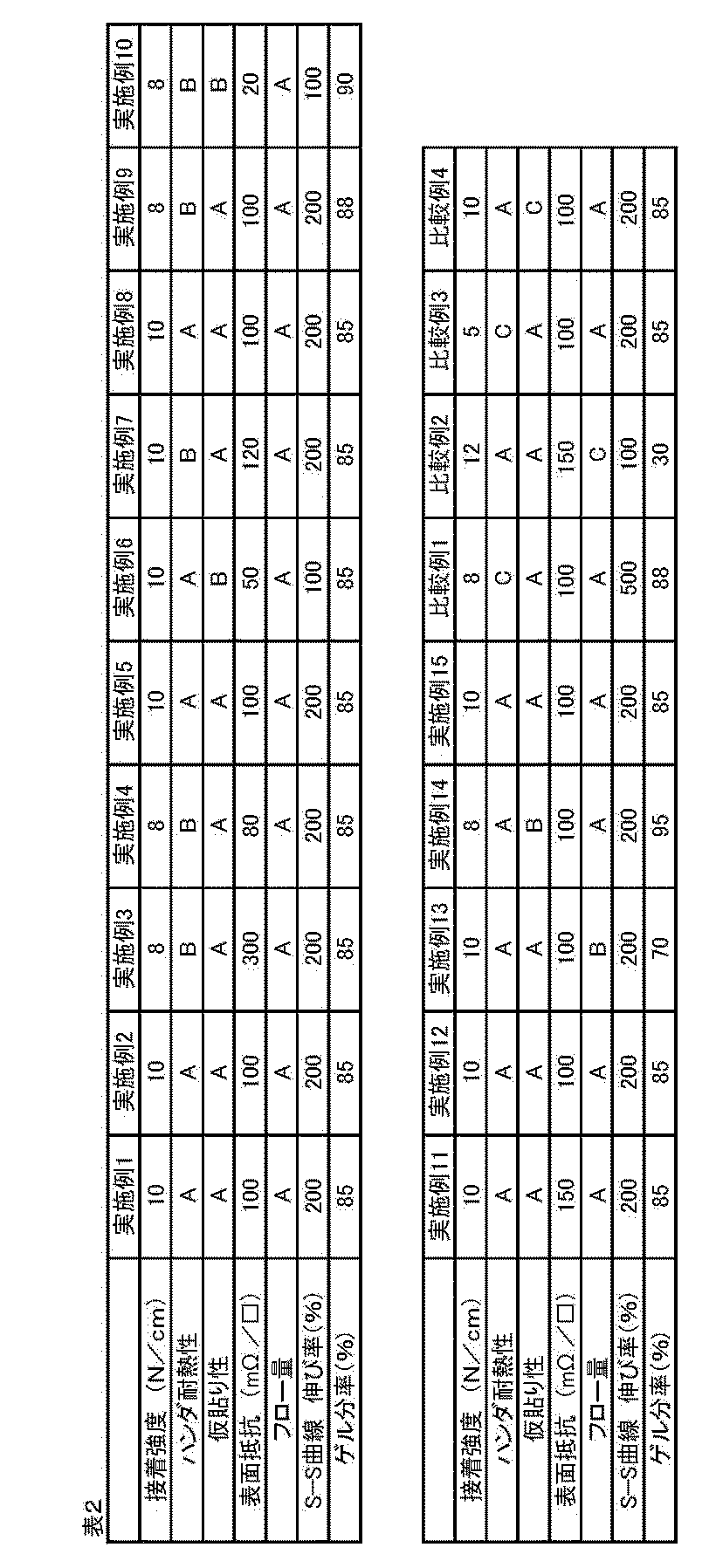
本発明の導電性接着剤は、カルボキシル基を有する熱硬化性樹脂(A)と、エポキシ樹脂(B)と、反応性官能基を有するエラストマー(C)と、導電性フィラー(D)と、硬化剤(E)とを含む。かかる本発明によれば、優れた仮貼り適正および打ち抜き加工性とともに、ハンダリフロー温度で耐えうる高い硬化後の耐熱性を有する導電性接着剤、かかる導電性接着剤から形成した導電性接着剤層を備える導電性接着シート、配線板と補強板とを、導電性接着剤層の硬化物で構成される接合層で接合してなる配線デバイス、およびかかる配線デバイスの製造方法を提供することができる。したがって、本発明は、産業上の利用可能性を有する。
Claims (10)
- カルボキシル基を有する熱硬化性樹脂(A)と、
エポキシ樹脂(B)と、
反応性官能基を有するエラストマー(C)と、
導電性フィラー(D)と、
硬化剤(E)とを含むことを特徴とする導電性接着剤。 - 当該導電性接着剤は、前記カルボキシル基を有する熱硬化性樹脂(A)100重量部に対して、3~200重量部の前記反応性官能基を有するエラストマー(C)を含む請求項1に記載の導電性接着剤。
- 前記反応性官能基を有するエラストマー(C)のガラス転移温度は、-70~0℃である請求項1に記載の導電性接着剤。
- 剥離性シートと、
該剥離性シートの一方の面側に設けられ、請求項1に記載の導電性接着剤から形成した導電性接着剤層とを備えることを特徴とする導電性接着シート。 - 前記導電性接着剤層のゲル分率は、60~95%である請求項4に記載の導電性接着シート。
- 信号配線を備える配線板と、
該配線板の一方の面側に設けられた補強板と、
前記配線板と前記補強板との間に設けられ、これらを接合する接合層であって、請求項1に記載の導電性接着剤から形成した導電性接着剤層の硬化物で構成された接合層とを備えることを特徴とする配線デバイス。 - 前記補強板は、導電性を有し、
前記配線板は、さらに、前記補強板に接続されたグランド配線を備える請求項6に記載の配線デバイス。 - 前記配線板は、フレキシブルプリント配線板である請求項6に記載の配線デバイス。
- 請求項6に記載の配線デバイスの製造方法であって、
前記配線板と、前記導電性接着剤層と、前記補強板とを用意する工程と、
前記導電性接着剤層を介して前記配線板と前記補強板とを積層して、積層体を得る工程と、
該積層体を130~210℃で加熱して、前記導電性接着剤層を硬化させることにより前記接合層を形成し、前記配線デバイスを得る工程とを備えることを特徴とする配線デバイスの製造方法。 - 前記積層体を加熱する工程において、前記積層体を0.2~12MPaで加圧する請求項9に記載の配線デバイスの製造方法。
Applications Claiming Priority (2)
| Application Number | Priority Date | Filing Date | Title |
|---|---|---|---|
| JP2013-231200 | 2013-11-07 | ||
| JP2013231200 | 2013-11-07 |
Publications (1)
| Publication Number | Publication Date |
|---|---|
| WO2015068611A1 true WO2015068611A1 (ja) | 2015-05-14 |
Family
ID=53041393
Family Applications (1)
| Application Number | Title | Priority Date | Filing Date |
|---|---|---|---|
| PCT/JP2014/078595 Ceased WO2015068611A1 (ja) | 2013-11-07 | 2014-10-28 | 導電性接着剤、導電性接着シート、配線デバイス、および配線デバイスの製造方法 |
Country Status (3)
| Country | Link |
|---|---|
| JP (1) | JP5928556B2 (ja) |
| TW (1) | TW201518471A (ja) |
| WO (1) | WO2015068611A1 (ja) |
Cited By (3)
| Publication number | Priority date | Publication date | Assignee | Title |
|---|---|---|---|---|
| CN110776847A (zh) * | 2018-07-27 | 2020-02-11 | 杭州蓉阳电子科技有限公司 | 一种导电胶、原料组合物、电子元件、制备方法和应用 |
| JP2020204027A (ja) * | 2019-06-12 | 2020-12-24 | 東洋インキScホールディングス株式会社 | 導電性接着剤、及びプリント配線板 |
| WO2022123999A1 (ja) * | 2020-12-10 | 2022-06-16 | 味の素株式会社 | 導電性接着フィルム |
Families Citing this family (15)
| Publication number | Priority date | Publication date | Assignee | Title |
|---|---|---|---|---|
| WO2016076096A1 (ja) * | 2014-11-12 | 2016-05-19 | デクセリアルズ株式会社 | 熱硬化性接着組成物 |
| JP2017118102A (ja) * | 2015-12-18 | 2017-06-29 | Dic株式会社 | 熱硬化性接着シート、補強部付フレキシブルプリント配線板、その製造方法及び電子機器 |
| KR102066730B1 (ko) * | 2017-08-18 | 2020-01-15 | 주식회사 네패스 | Emi 차폐필름 |
| JP6714631B2 (ja) * | 2018-03-15 | 2020-06-24 | タツタ電線株式会社 | 電磁波シールドフィルム及びシールドプリント配線板 |
| KR20200038814A (ko) | 2018-10-04 | 2020-04-14 | 주식회사 엘지화학 | 회로 기판 제조용 연속 시트의 제조 방법 및 이로부터 제조된 회로 기판 제조용 연속 시트 |
| TWI796476B (zh) | 2018-10-22 | 2023-03-21 | 日商拓自達電線股份有限公司 | 導電性接著片 |
| WO2020122166A1 (ja) * | 2018-12-12 | 2020-06-18 | タツタ電線株式会社 | シールドプリント配線板及びシールドプリント配線板の製造方法 |
| CN113748161A (zh) * | 2019-04-26 | 2021-12-03 | 东亚合成株式会社 | 树脂组合物、接合膜、带有树脂组合物层的层叠体、层叠体、及电磁波屏蔽膜 |
| TWI815049B (zh) | 2019-12-03 | 2023-09-11 | 日商拓自達電線股份有限公司 | 電磁波屏蔽膜 |
| KR102669973B1 (ko) | 2020-01-07 | 2024-05-27 | 타츠타 전선 주식회사 | 전자파 차폐 필름 |
| TWI842957B (zh) | 2020-02-26 | 2024-05-21 | 日商拓自達電線股份有限公司 | 電磁波屏蔽膜 |
| CN111440580A (zh) * | 2020-04-23 | 2020-07-24 | 东莞市中凌包装材料有限公司 | 一种水性基于apao的一次性医用包装热熔胶及制作工艺 |
| JP7107344B2 (ja) * | 2020-10-06 | 2022-07-27 | 東洋インキScホールディングス株式会社 | 金属板用接合剤、プリント配線板用補強部材及びその製造方法、並びに、配線板及びその製造方法 |
| CN116390855A (zh) * | 2020-10-23 | 2023-07-04 | 东亚合成株式会社 | 树脂组合物、粘结膜、带有树脂组合物层的层叠体、层叠体以及电磁波屏蔽膜 |
| JP7759533B1 (ja) | 2024-06-20 | 2025-10-24 | artience株式会社 | 接着剤組成物、硬化物、接着シートおよび燃料電池用部材、並びにウレタンウレア樹脂の製造方法 |
Citations (13)
| Publication number | Priority date | Publication date | Assignee | Title |
|---|---|---|---|---|
| JP2000100872A (ja) * | 1998-09-17 | 2000-04-07 | Sony Corp | 電子部品装置およびそのリペアー方法 |
| JP2002285103A (ja) * | 2001-03-26 | 2002-10-03 | Sumitomo Bakelite Co Ltd | 異方導電性接着剤 |
| JP2003168323A (ja) * | 2001-11-30 | 2003-06-13 | Mitsui Chemicals Inc | 異方性導電ペーストおよびその使用方法 |
| JP2004352785A (ja) * | 2003-05-27 | 2004-12-16 | Sumitomo Bakelite Co Ltd | 異方導電性接着剤 |
| JP2006318990A (ja) * | 2005-05-10 | 2006-11-24 | Hitachi Chem Co Ltd | 回路接続材料、回路部材の接続構造及び回路部材の接続方法。 |
| WO2009090997A1 (ja) * | 2008-01-15 | 2009-07-23 | Toyo Ink Manufacturing Co., Ltd. | 硬化性電磁波シールド性接着性フィルム、その製造方法、及びその使用方法、並びに電磁波遮蔽物の製造方法及び電磁波遮蔽物 |
| JP2009263590A (ja) * | 2008-04-30 | 2009-11-12 | Toyo Ink Mfg Co Ltd | ポリウレタンポリウレア接着剤、それを用いた硬化性電磁波シールド性接着性フィルム及びその製造方法 |
| JP2010143981A (ja) * | 2008-12-17 | 2010-07-01 | Toyo Ink Mfg Co Ltd | 硬化性導電性ポリウレタンポリウレア接着剤組成物、硬化性電磁波シールド性接着性フィルムおよびその製造方法 |
| JP2010219039A (ja) * | 1997-03-31 | 2010-09-30 | Hitachi Chem Co Ltd | 回路接続材料並びに回路端子の接続構造及び接続方法 |
| JP2011111474A (ja) * | 2009-11-24 | 2011-06-09 | Hitachi Chem Co Ltd | 回路接続材料 |
| JP2013125598A (ja) * | 2011-12-13 | 2013-06-24 | Sumitomo Electric Ind Ltd | フィルム状異方導電性接着剤 |
| JP2013143292A (ja) * | 2012-01-11 | 2013-07-22 | Sekisui Chem Co Ltd | 異方性導電フィルム材料、接続構造体及び接続構造体の製造方法 |
| WO2014010524A1 (ja) * | 2012-07-11 | 2014-01-16 | タツタ電線株式会社 | 硬化性導電性接着剤組成物、電磁波シールドフィルム、導電性接着フィルム、接着方法及び回路基板 |
Family Cites Families (11)
| Publication number | Priority date | Publication date | Assignee | Title |
|---|---|---|---|---|
| JPS63280785A (ja) * | 1987-05-14 | 1988-11-17 | Mitsui Toatsu Chem Inc | 構造用接着剤 |
| JPH07157740A (ja) * | 1993-12-07 | 1995-06-20 | Nissan Motor Co Ltd | 接着性樹脂組成物 |
| JP3532749B2 (ja) * | 1997-12-29 | 2004-05-31 | 株式会社巴川製紙所 | 導電性組成物、それを用いた導電性接着剤 |
| JP4469089B2 (ja) * | 1999-02-08 | 2010-05-26 | 日立化成工業株式会社 | 回路接続用フィルム状異方導電性接着剤、電極の接続構造及び電極の接続方法 |
| JP2002368043A (ja) * | 2001-06-12 | 2002-12-20 | Matsushita Electric Ind Co Ltd | 導電性ペーストとそれを用いた導電性バンプおよびその形成方法、導電性バンプの接続方法、並びに回路基板とその製造方法 |
| KR100527990B1 (ko) * | 2001-11-30 | 2005-11-09 | 미쯔이카가쿠 가부시기가이샤 | 회로 접속용 페이스트, 이방성 도전 페이스트 및 이들의사용방법 |
| JP2006124531A (ja) * | 2004-10-29 | 2006-05-18 | Shin Etsu Chem Co Ltd | 異方導電性接着剤 |
| KR101552759B1 (ko) * | 2007-08-08 | 2015-09-11 | 히타치가세이가부시끼가이샤 | 접착제 조성물, 필름상 접착제 및 회로 부재의 접속 구조 |
| CN101940080B (zh) * | 2008-01-15 | 2013-01-02 | 东洋油墨制造株式会社 | 固化性电磁波屏蔽性粘合性膜,其制造方法和其使用方法,以及电磁波屏蔽物的制造方法和电磁波屏蔽物 |
| KR101741292B1 (ko) * | 2010-07-23 | 2017-05-29 | 다츠다 덴센 가부시키가이샤 | 접착제 조성물 및 접착 필름 |
| WO2014003159A1 (ja) * | 2012-06-29 | 2014-01-03 | タツタ電線株式会社 | 導電性接着剤組成物、導電性接着フィルム、接着方法及び回路基板 |
-
2014
- 2014-10-28 WO PCT/JP2014/078595 patent/WO2015068611A1/ja not_active Ceased
- 2014-11-04 TW TW103138122A patent/TW201518471A/zh unknown
- 2014-11-06 JP JP2014226400A patent/JP5928556B2/ja active Active
Patent Citations (13)
| Publication number | Priority date | Publication date | Assignee | Title |
|---|---|---|---|---|
| JP2010219039A (ja) * | 1997-03-31 | 2010-09-30 | Hitachi Chem Co Ltd | 回路接続材料並びに回路端子の接続構造及び接続方法 |
| JP2000100872A (ja) * | 1998-09-17 | 2000-04-07 | Sony Corp | 電子部品装置およびそのリペアー方法 |
| JP2002285103A (ja) * | 2001-03-26 | 2002-10-03 | Sumitomo Bakelite Co Ltd | 異方導電性接着剤 |
| JP2003168323A (ja) * | 2001-11-30 | 2003-06-13 | Mitsui Chemicals Inc | 異方性導電ペーストおよびその使用方法 |
| JP2004352785A (ja) * | 2003-05-27 | 2004-12-16 | Sumitomo Bakelite Co Ltd | 異方導電性接着剤 |
| JP2006318990A (ja) * | 2005-05-10 | 2006-11-24 | Hitachi Chem Co Ltd | 回路接続材料、回路部材の接続構造及び回路部材の接続方法。 |
| WO2009090997A1 (ja) * | 2008-01-15 | 2009-07-23 | Toyo Ink Manufacturing Co., Ltd. | 硬化性電磁波シールド性接着性フィルム、その製造方法、及びその使用方法、並びに電磁波遮蔽物の製造方法及び電磁波遮蔽物 |
| JP2009263590A (ja) * | 2008-04-30 | 2009-11-12 | Toyo Ink Mfg Co Ltd | ポリウレタンポリウレア接着剤、それを用いた硬化性電磁波シールド性接着性フィルム及びその製造方法 |
| JP2010143981A (ja) * | 2008-12-17 | 2010-07-01 | Toyo Ink Mfg Co Ltd | 硬化性導電性ポリウレタンポリウレア接着剤組成物、硬化性電磁波シールド性接着性フィルムおよびその製造方法 |
| JP2011111474A (ja) * | 2009-11-24 | 2011-06-09 | Hitachi Chem Co Ltd | 回路接続材料 |
| JP2013125598A (ja) * | 2011-12-13 | 2013-06-24 | Sumitomo Electric Ind Ltd | フィルム状異方導電性接着剤 |
| JP2013143292A (ja) * | 2012-01-11 | 2013-07-22 | Sekisui Chem Co Ltd | 異方性導電フィルム材料、接続構造体及び接続構造体の製造方法 |
| WO2014010524A1 (ja) * | 2012-07-11 | 2014-01-16 | タツタ電線株式会社 | 硬化性導電性接着剤組成物、電磁波シールドフィルム、導電性接着フィルム、接着方法及び回路基板 |
Cited By (9)
| Publication number | Priority date | Publication date | Assignee | Title |
|---|---|---|---|---|
| CN110776847A (zh) * | 2018-07-27 | 2020-02-11 | 杭州蓉阳电子科技有限公司 | 一种导电胶、原料组合物、电子元件、制备方法和应用 |
| JP2021524881A (ja) * | 2018-07-27 | 2021-09-16 | 杭州蓉陽電子科技有限公司 | 導電性接着剤、原料組成物、電子部品、製造方法及び使用 |
| CN110776847B (zh) * | 2018-07-27 | 2021-11-12 | 嘉兴蓉阳电子科技有限公司 | 一种导电胶、原料组合物、电子元件、制备方法和应用 |
| JP7196200B2 (ja) | 2018-07-27 | 2022-12-26 | 嘉興蓉陽電子科技有限公司 | 導電性接着剤、原料組成物、電子部品、製造方法及び使用 |
| JP2020204027A (ja) * | 2019-06-12 | 2020-12-24 | 東洋インキScホールディングス株式会社 | 導電性接着剤、及びプリント配線板 |
| JP2021121018A (ja) * | 2019-06-12 | 2021-08-19 | 東洋インキScホールディングス株式会社 | プリント配線板 |
| JP7099580B2 (ja) | 2019-06-12 | 2022-07-12 | 東洋インキScホールディングス株式会社 | プリント配線板 |
| WO2022123999A1 (ja) * | 2020-12-10 | 2022-06-16 | 味の素株式会社 | 導電性接着フィルム |
| JPWO2022123999A1 (ja) * | 2020-12-10 | 2022-06-16 |
Also Published As
| Publication number | Publication date |
|---|---|
| JP5928556B2 (ja) | 2016-06-01 |
| TW201518471A (zh) | 2015-05-16 |
| JP2015110769A (ja) | 2015-06-18 |
Similar Documents
| Publication | Publication Date | Title |
|---|---|---|
| JP5928556B2 (ja) | 導電性接着シート、配線デバイス、および配線デバイスの製造方法 | |
| JP5892282B1 (ja) | 導電性接着剤、導電性接着シート、および配線デバイス | |
| JP4114706B2 (ja) | 電磁波シールド性接着フィルム及びその製造方法、並びに被着体の電磁波遮蔽方法 | |
| CN101268163B (zh) | 粘结剂组合物、使用它的粘结剂片及其应用 | |
| JP5931305B1 (ja) | 導電性接着剤組成物 | |
| JP2009289840A (ja) | 電磁波シールド性接着フィルム | |
| JP2010229282A (ja) | ポリウレタンポリウレア樹脂組成物、それを用いた硬化性電磁波シールド性接着性フィルム及びその製造方法 | |
| JP7099580B2 (ja) | プリント配線板 | |
| JP2009096940A (ja) | 難燃性接着剤組成物、カバーレイおよび接着剤シート、フレキシブルプリント配線板 | |
| JP2009290195A (ja) | 硬化性電磁波シールド性接着性フィルムおよびその製造方法 | |
| JP2009277980A (ja) | 電磁波シールド性接着フィルムおよびその製造方法 | |
| JP5233392B2 (ja) | ポリウレタンポリウレア接着剤、それを用いた硬化性電磁波シールド性接着性フィルム及びその製造方法 | |
| JP4806944B2 (ja) | 接着剤組成物、それを用いた接着剤シート、および補強材付きフレキシブルプリント配線板 | |
| JP2009194353A (ja) | 硬化性電磁波シールド性接着性フィルムおよびその製造方法 | |
| JP5104778B2 (ja) | 硬化性電磁波シールド性接着性フィルムおよびその製造方法 | |
| JP6508078B2 (ja) | 導電性接着剤、導電性接着シート、および配線デバイス | |
| WO2009090997A1 (ja) | 硬化性電磁波シールド性接着性フィルム、その製造方法、及びその使用方法、並びに電磁波遮蔽物の製造方法及び電磁波遮蔽物 | |
| JP2010143981A (ja) | 硬化性導電性ポリウレタンポリウレア接着剤組成物、硬化性電磁波シールド性接着性フィルムおよびその製造方法 | |
| JP2014078573A (ja) | 電磁波シールド性カバーレイフィルム、フレキシブルプリント配線板の製造方法、及びフレキシブルプリント配線板 | |
| JP5286740B2 (ja) | 接着剤組成物、それを用いた接着剤シート、および補強材付きフレキシブルプリント配線板 | |
| JP2010238870A (ja) | 電磁波シールド性カバーレイフィルム、フレキシブルプリント配線板の製造方法、及びフレキシブルプリント配線板。 | |
| JP2007073738A (ja) | 接着剤層付き補強材および補強材付きフレキシブルプリント配線板並びにその製造方法 | |
| JP2007070471A (ja) | 接着剤層付きプラスチックフィルムおよびカバーフィルム付きフレキシブルプリント配線板並びにその製造方法 | |
| JP2007073737A (ja) | 複数の導電性回路層を有するプリント配線板並びにその製造方法 | |
| JP4957550B2 (ja) | 接着剤組成物、それを用いた接着剤シート、並びにそれらの利用 |
Legal Events
| Date | Code | Title | Description |
|---|---|---|---|
| 121 | Ep: the epo has been informed by wipo that ep was designated in this application |
Ref document number: 14859835 Country of ref document: EP Kind code of ref document: A1 |
|
| NENP | Non-entry into the national phase |
Ref country code: DE |
|
| 122 | Ep: pct application non-entry in european phase |
Ref document number: 14859835 Country of ref document: EP Kind code of ref document: A1 |