WO2015064116A1 - 画像取得装置及び画像取得装置の画像取得方法 - Google Patents
画像取得装置及び画像取得装置の画像取得方法 Download PDFInfo
- Publication number
- WO2015064116A1 WO2015064116A1 PCT/JP2014/051804 JP2014051804W WO2015064116A1 WO 2015064116 A1 WO2015064116 A1 WO 2015064116A1 JP 2014051804 W JP2014051804 W JP 2014051804W WO 2015064116 A1 WO2015064116 A1 WO 2015064116A1
- Authority
- WO
- WIPO (PCT)
- Prior art keywords
- image acquisition
- speed
- sample
- image
- image sensor
- Prior art date
Links
Images

Classifications
-
- G—PHYSICS
- G06—COMPUTING OR CALCULATING; COUNTING
- G06V—IMAGE OR VIDEO RECOGNITION OR UNDERSTANDING
- G06V20/00—Scenes; Scene-specific elements
- G06V20/60—Type of objects
- G06V20/69—Microscopic objects, e.g. biological cells or cellular parts
- G06V20/693—Acquisition
-
- G—PHYSICS
- G02—OPTICS
- G02B—OPTICAL ELEMENTS, SYSTEMS OR APPARATUS
- G02B21/00—Microscopes
- G02B21/06—Means for illuminating specimens
-
- G—PHYSICS
- G02—OPTICS
- G02B—OPTICAL ELEMENTS, SYSTEMS OR APPARATUS
- G02B21/00—Microscopes
- G02B21/24—Base structure
- G02B21/26—Stages; Adjusting means therefor
-
- G—PHYSICS
- G02—OPTICS
- G02B—OPTICAL ELEMENTS, SYSTEMS OR APPARATUS
- G02B21/00—Microscopes
- G02B21/36—Microscopes arranged for photographic purposes or projection purposes or digital imaging or video purposes including associated control and data processing arrangements
- G02B21/365—Control or image processing arrangements for digital or video microscopes
- G02B21/367—Control or image processing arrangements for digital or video microscopes providing an output produced by processing a plurality of individual source images, e.g. image tiling, montage, composite images, depth sectioning, image comparison
-
- G—PHYSICS
- G02—OPTICS
- G02B—OPTICAL ELEMENTS, SYSTEMS OR APPARATUS
- G02B21/00—Microscopes
- G02B21/06—Means for illuminating specimens
- G02B21/08—Condensers
- G02B21/086—Condensers for transillumination only
-
- H—ELECTRICITY
- H04—ELECTRIC COMMUNICATION TECHNIQUE
- H04N—PICTORIAL COMMUNICATION, e.g. TELEVISION
- H04N23/00—Cameras or camera modules comprising electronic image sensors; Control thereof
- H04N23/60—Control of cameras or camera modules
- H04N23/698—Control of cameras or camera modules for achieving an enlarged field of view, e.g. panoramic image capture
Definitions
- the present invention relates to an image acquisition device and an image acquisition method of the image acquisition device.
- an image acquisition device for acquiring a still image of a sample such as a tissue cell
- Partial images are acquired sequentially, and then the partial images are combined to acquire an image of the entire sample.
- an image acquisition method called a tiling scan method is used.
- the stage is moved so that a predetermined region of the sample is included in the field of view of the objective lens, and then the partial image is acquired using a two-dimensional imaging device such as an area sensor while the stage is stopped. . Thereafter, the same operation is repeatedly executed to acquire a still image of the entire sample.
- Patent Documents 1 to 3 propose an image acquisition method for acquiring a partial image using a two-dimensional image sensor without stopping the stage. More specifically, for example, in the image acquisition method described in Patent Document 1, the stage is moved and the sample is intermittently irradiated with light in synchronization with the movement of the stage, while continuously using a two-dimensional image sensor. Partial images are acquired.
- the present invention has been made to solve the above problems, and an object thereof is to provide an image acquisition device and an image acquisition method for the image acquisition device that can execute partial image acquisition and overall image synthesis at high speed. .
- an image acquisition apparatus includes a stage on which a sample is placed, a light emitting unit that irradiates instantaneous light, and an objective lens that is disposed so as to face the sample on the stage.
- a light guide optical system Including a light guide optical system, an image pickup device for picking up a light image of the sample guided by the light guide optical system, a drive unit for moving the visual field position of the objective lens with respect to the sample at a predetermined speed, and controlling the light emitting means
- a control unit that has a plurality of pixel columns and sequentially captures images at a predetermined frame rate, and the speed is a speed set based on at least the frame rate. It is characterized by being.
- the drive unit moves the visual field position of the objective lens with respect to the sample at a predetermined speed, and the two-dimensional image sensor sequentially captures the optical image of the sample at a predetermined frame rate. Therefore, the time required for acquiring the partial image over the entire sample is shortened.
- the moving speed of the visual field position is a speed set based on the frame rate of the image sensor. Therefore, the movement of the visual field position is synchronized with the imaging of the imaging device, and it is possible to capture only the necessary partial images. Therefore, in this image acquisition device, partial image acquisition and overall image synthesis can be performed at high speed.
- the predetermined speed is preferably a speed set based on at least the number of pixel columns of the image sensor.
- the moving speed of the visual field position is set in consideration of the relationship between the number of pixel columns of the image sensor and the sample area captured by one imaging, only necessary partial images are captured more reliably. It becomes possible.
- the predetermined speed is preferably a speed set based on at least the optical magnification of the light guide optical system.
- the moving speed of the visual field position is set in consideration of the size of the visual field of the objective lens, it is possible to capture an image at a desired position more reliably.
- the predetermined speed is preferably a speed set based on at least the pixel width of the pixel row of the image sensor. In this case, since the moving speed of the visual field position is set in consideration of the pixel width of the image sensor, it is possible to capture more reliably at a desired position.
- the predetermined speed is a speed that is set so that a part of two regions of the sample continuously imaged by the image sensor overlap each other. In this case, part of the two regions of the sample that are continuously imaged overlap each other, so that when the obtained partial images are synthesized, the partial images can be smoothly synthesized, and the whole image without a break is obtained. You can get it.
- the predetermined speed is a speed set based on the number of pixel columns of the image sensor corresponding to the overlapping area where two areas partially overlap each other. In this case, since the moving speed of the visual field position is set in consideration of the relationship between the overlapping region and the number of pixel columns of the image sensor corresponding to the region, the overlapping region is more reliably formed.
- the imaging device outputs a trigger signal indicating that all of the pixel columns are exposed to the control unit, and the control unit exposes all of the pixel columns based on the trigger signal output from the imaging device. It is preferable to irradiate instantaneous light from the light emitting means during the period. In this case, since it is possible to irradiate instantaneous light during a period in which all of the pixel columns are exposed, each partial image can be reliably acquired.
- An image acquisition method of an image acquisition apparatus includes a stage on which a sample is placed, a light emitting means for irradiating instantaneous light, and a light guide including an objective lens arranged to face the sample on the stage.
- An optical system an imaging device that captures a light image of the sample guided by the light guide optical system, a drive unit that moves the visual field position of the objective lens with respect to the sample at a predetermined speed, and a control unit that controls the light emitting means
- An image acquisition method of an image acquisition apparatus comprising: a two-dimensional image sensor that has a plurality of pixel rows and sequentially images at a predetermined frame rate as an image sensor; It is characterized by setting based on the rate.
- the drive unit moves the visual field position of the objective lens with respect to the sample at a predetermined speed, and the two-dimensional image sensor sequentially captures the optical image of the sample at a predetermined frame rate. Therefore, the time required for acquiring the partial image over the entire sample is shortened.
- the moving speed of the visual field position is set based on the frame rate of the image sensor. Therefore, the movement of the visual field position is synchronized with the imaging of the imaging device, and it is possible to capture only the necessary partial images. Therefore, in this image acquisition method of the image acquisition device, partial image acquisition and overall image synthesis can be performed at high speed.
- the predetermined speed based on at least the number of pixel columns of the image sensor.
- the moving speed of the visual field position is set in consideration of the relationship between the number of pixel rows of the image sensor and the sample area captured by one imaging, only necessary partial images are captured more reliably. Is possible.
- the predetermined speed it is preferable to set the predetermined speed so that a part of two regions of the sample continuously imaged by the image sensor overlap each other. In this case, part of the two regions of the sample that are continuously imaged overlap each other, so that when the obtained partial images are synthesized, the partial images can be smoothly synthesized, and the whole image without a break is obtained. You can get it.
- FIG. 1 It is a figure which shows one Embodiment of the image acquisition apparatus which concerns on this invention. It is a figure which shows the light-receiving surface of the image pick-up element which comprises the image acquisition apparatus shown in FIG. It is a figure which shows an example of the scan of the image acquisition area
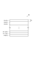
- FIG. 1 is a diagram showing an embodiment of an image acquisition apparatus according to the present invention.
- the image acquisition apparatus 1 includes a stage 2 on which a sample S is placed, a light source 3 (light emitting means) that irradiates instantaneous light toward the sample, and a sample S on the stage 2.
- the light guide optical system 5 including the objective lens 25 arranged in such a manner and the image sensor 6 that captures the light image of the sample S guided by the light guide optical system 5 are provided.
- the image acquisition apparatus 1 also includes a stage drive unit 11 (drive unit) that moves the visual field position of the objective lens 25 with respect to the sample S, an objective lens drive unit 12 that changes the focal position of the objective lens 25 with respect to the sample S, and a light source.
- a stage drive unit 11 drive unit
- an objective lens drive unit 12 that changes the focal position of the objective lens 25 with respect to the sample S
- a light source 3 includes a light source control unit 13 (control unit) that controls the image processing unit 14 and an image processing unit 14.
- the sample S observed by the image acquisition device 1 is a biological sample such as tissue cells, for example, and is placed on the stage 2 in a state of being sealed in a slide glass.
- the light source 3 is disposed on the bottom surface side of the stage 2.
- a flash lamp type light source such as a laser diode (LD), a light emitting diode (LED), a super luminescent diode (SLD), or a xenon flash lamp is used.
- the light guide optical system 5 includes an illumination optical system 21 disposed between the light source 3 and the stage 2 and a microscope optical system 22 disposed between the stage 2 and the image sensor 6.
- the illumination optical system 21 has a Koehler illumination optical system composed of, for example, a condenser lens 23 and a projection lens 24.
- the illumination optical system 21 guides light from the light source 3 and irradiates the sample S with uniform light. ing.
- the microscope optical system 22 includes an objective lens 25 and an imaging lens 26 disposed on the rear stage side (imaging element 6 side) of the objective lens 25, and guides the optical image of the sample S to the imaging element 6.
- the light image of the sample S is an image by transmitted light in the case of bright field illumination, scattered light in the case of dark field illumination, and light emission (fluorescence) in the case of light emission measurement. Moreover, the image by the reflected light from the sample S may be sufficient.
- the light guide optical system 5 an optical system corresponding to image acquisition of a transmitted light image, a scattered light image, and a light emission (fluorescence) image of the sample S can be employed.
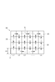
- the image sensor 6 is a two-dimensional image sensor having a plurality of pixel columns. Examples of such an image sensor 6 include a CCD image sensor and a CMOS image sensor. On the light receiving surface 6a of the image sensor 6, as shown in FIG. 2, for example, a pixel row 31 (a first pixel row 31 1 , a second pixel row 31 2 , 3 pixel columns 31 3 ,..., M-2th pixel column 31 M-2 , M ⁇ 1th pixel column 31 M ⁇ 1 , and Mth pixel column 31 M ) are arranged in parallel with each other. It is arranged. The length (pixel width) P in the arrangement direction (reading direction) of each pixel column 31 is, for example, about 1.5 ⁇ m.
- the image sensor 6 sequentially captures the optical image of the sample S guided by the light guide optical system 5 at a predetermined frame rate ⁇ (for example, less than 30 fps (Frames Per Second)).
- the stage drive unit 11 is configured by a motor such as a stepping motor (pulse motor) or an actuator such as a piezo actuator.
- the stage drive unit 11 drives the stage 2 in the XY directions with respect to a plane having a predetermined angle (for example, 90 degrees) with respect to a plane orthogonal to the optical axis of the objective lens 25.
- a predetermined angle for example, 90 degrees
- the sample S is imaged at a high magnification such as 20 times or 40 times.
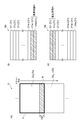
- the field of view F of the objective lens 25 is small with respect to the sample S, and the region where an image can be acquired by one imaging is also small with respect to the sample S as shown in FIG. Therefore, in order to image the entire sample S, it is necessary to move the field of view F of the objective lens 25 with respect to the sample S.
- the image acquisition region 32 is set so as to include the sample S with respect to the sample container (for example, a slide glass) holding the sample S, and the image acquisition region 32 and the objective lens 25 on the sample S are set. Based on the field of view F, the positions of the plurality of divided regions 33 are set. Then, by capturing a part of the sample S corresponding to the divided region 33 and acquiring partial image data corresponding to the divided region 33, the field of view F of the objective lens 25 and the position of the divided region 33 to be imaged next are obtained. Then, image capturing is performed again to acquire partial image data. Thereafter, in the image acquisition device 1, this operation is repeatedly executed, and the image processing unit 14 combines the acquired partial image data to form an entire image (synthesized image data) of the sample S.
- the sample container for example, a slide glass
- the stage drive unit 11 moves the stage 2 so that the position of the field of view F of the objective lens 25 with respect to the sample S moves in the scanning direction along the imaging line Ln (n is a natural number) composed of a plurality of divided regions 33.
- the imaging line Ln (n is a natural number) composed of a plurality of divided regions 33.
- a bidirectional scan in which the scanning direction is reversed between the adjacent imaging lines Ln is employed.
- unidirectional scanning in which the scanning direction is the same between adjacent imaging lines Ln may be employed.
- the direction along the imaging line Ln corresponds to the arrangement direction of the pixel columns 31 on the light receiving surface 6a of the imaging element 6.
- the stage driving unit 11 drives the stage 2 at a speed set based on the frame rate ⁇ of the image sensor 6. That is, the stage drive unit 11 drives the stage 2 at such a speed that the timing at which the field of view F of the objective lens 25 becomes the position of each divided region 33 and the timing at which the image sensor 6 captures images.
- the stage drive unit 11 drives the stage 2 at a speed V expressed by the following formula (1) based on, for example, the number M of pixel columns in the pixel column 31.
- V A ⁇ M ⁇ ⁇ (1)
- the stage drive part 11 is driving the stage 2 with the speed V shown, for example by following formula (2) which rewritten Formula (1).
- V H1 ⁇ ⁇ (2)
- H1 represents the length of the visual field F of the objective lens 25 in the direction along the imaging line Ln.
- the objective lens driving unit 12 is configured by a motor such as a stepping motor (pulse motor) or an actuator such as a piezo actuator, similarly to the stage driving unit 11.
- the objective lens driving unit 12 drives the objective lens 25 in the Z direction along the optical axis of the objective lens 25. Thereby, the focal position of the objective lens 25 with respect to the sample S moves.
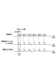
- the light source controller 13 emits instantaneous light from the light source 3 as shown in FIG. That is, first, the image sensor 6 alternately performs exposure and readout, and then performs pixel columns 31 (first pixel column 31 1 , second pixel column 31 2 , third pixel column 31 3 ... Mth The trigger signal is output to the light source controller 13 when all of the pixel columns 31 M ) are exposed.
- the light source control unit 13 causes the light source 3 to irradiate instantaneous light based on a trigger signal indicating that all of the pixel columns 31 output from the image sensor 6 are exposed.
- the stage driving unit 11 drives the stage 2 to move the position of the field of view F of the objective lens 25 with respect to the sample S, and the imaging element 6 that is a two-dimensional imaging element.
- a light image of the sample S is sequentially captured at a predetermined frame rate ⁇ . Therefore, the time for acquiring the partial image over the entire sample S is shortened.
- the stage drive unit 11 drives the stage 2 at a speed based on the frame rate ⁇ of the image sensor 6. Therefore, driving of the stage 2 (movement of the position of the field of view F of the objective lens 25) and imaging are performed so that the timing when the field of view F of the objective lens 25 becomes the position of each divided region 33 coincides with the timing of imaging by the imaging device 6. Since the imaging of the element 6 is synchronized, it is possible to capture only partial images corresponding to the divided regions 33. Therefore, the image acquisition device 1 can execute acquisition of partial images and synthesis of the entire image at high speed.
- the light source control unit 13 outputs the light from the light source 3 during the period in which all the pixel columns 31 are exposed based on the trigger signal indicating that all the pixel columns 31 output from the image sensor 6 are exposed. Irradiate momentary light. Therefore, partial images can be reliably acquired in all of the divided regions 33.
- the present invention is not limited to the above embodiment.
- the light source control unit 13 irradiates the instantaneous light from the light source 3 based on the trigger signal output from the image sensor 6, but the light source control unit 13 is the timing to irradiate the instantaneous light from the light source 3. Is set to be synchronized with the timing at which the image sensor 6 captures an image based on the frame rate ⁇ of the image sensor 6, so that the instantaneous light is emitted from the light source 3 during the period when all the pixel columns 31 are exposed. Also good. Even in this case, partial images can be reliably acquired in all of the divided regions 33.
- instantaneous light is emitted from the light source 3, but continuous light (CW light) may be emitted from the light source 3, and a shutter may be provided between the light source 3 and the sample S.
- the light emitting means is composed of the light source 3 and the shutter, and the light source control unit 13 controls the opening and closing of the shutter, thereby irradiating the sample S with the instantaneous light during the period in which all the pixel columns 31 are exposed. It becomes possible to make it.
- the stage driving unit 11 drives the stage 2 to move the visual field position of the objective lens 25 with respect to the sample S.
- the light guide optical system 5 including the objective lens 25 is guided.
- An optical optical system drive unit (drive unit) may be provided, and the visual field position of the objective lens 25 with respect to the sample S may be moved by the light guide optical system drive unit.
- the objective lens driving unit 12 moves the objective lens 25 in the optical axis direction, thereby moving the focal position of the objective lens 25 with respect to the sample S in the optical axis direction of the objective lens 25.
- the stage drive unit 11 may move the stage 2 in the optical axis direction of the objective lens 25, thereby moving the focal position of the objective lens 25 with respect to the sample S in the optical axis direction of the objective lens 25.
- the stage driving unit 11 drives the stage 2 so that the two divided regions 33 that are continuously imaged are in contact with each other.
- the stage driving unit 11 has two images that are continuously imaged.
- the stage 2 may be driven so that parts of the two divided regions 33 overlap each other.
- the stage drive part 11 may drive the stage 2 so as overlap region R where a part of the divided regions 33 S and a part of the divided regions 33 S + 1 is overlapped is formed.
- the stage drive unit 11 drives the stage 2 at a speed V ′ represented by the following equation (4) based on the number N of pixel columns on the light receiving surface 6a of the image sensor 6 corresponding to the overlapping region R, for example. can do.
- V ′ A ⁇ (MN) ⁇ ⁇ (4)
- the field of view F of the objective lens 25 is divided regions 33 when a position of the S + 1, for example of the image pickup device 6 first in the light receiving surface 6a pixel columns 31 1 and the second pixel column 31 2 correspond to the overlap region R.
- the stage 2 is driven at a speed V ′ indicated by
- V ′ (H1 ⁇ H2) ⁇ ⁇ (5)
- H2 represents the length of the overlapping region R in the direction along the imaging line Lt.
- the driving speed of the stage 2 is set in consideration of the relationship between the overlapping region R and the number N of pixel columns on the light receiving surface 6a of the image sensor 6 corresponding to the overlapping region R, the overlapping region R is formed reliably.
- the partial images can be synthesized smoothly, and an unbroken whole image can be acquired.
- SYMBOLS 1 ... Image acquisition device, 2 ... Stage, 3 ... Light source (light emission means), 5 ... Light guide optical system, 6 ... Image pick-up element, 11 ... Stage drive part (drive part), 12 ... Objective lens drive part, 13 ... Light source control unit (control unit), 14 ... image processing unit, 22 ... microscope optical system, 25 ... objective lens, 31 ... pixel array, 32 ... image acquisition region, 33 ... divided region, F ... field of view of objective lens, R ... Overlapping area, S ... sample.
Landscapes
- Physics & Mathematics (AREA)
- Engineering & Computer Science (AREA)
- Multimedia (AREA)
- General Physics & Mathematics (AREA)
- Chemical & Material Sciences (AREA)
- Analytical Chemistry (AREA)
- Optics & Photonics (AREA)
- Computer Vision & Pattern Recognition (AREA)
- Health & Medical Sciences (AREA)
- Life Sciences & Earth Sciences (AREA)
- Biomedical Technology (AREA)
- General Health & Medical Sciences (AREA)
- Molecular Biology (AREA)
- Theoretical Computer Science (AREA)
- Microscoopes, Condenser (AREA)
- Studio Devices (AREA)
- Image Input (AREA)
Priority Applications (4)
| Application Number | Priority Date | Filing Date | Title |
|---|---|---|---|
| EP14856848.8A EP3064981B1 (en) | 2013-11-01 | 2014-01-28 | Image acquisition device and image acquisition method for image acquisition device |
| DK14856848.8T DK3064981T3 (da) | 2013-11-01 | 2014-01-28 | Billedregistreringsanordning og fremgangsmåde til billedregistrering til billedregistreringsanordning |
| CN201480058554.5A CN105683805B (zh) | 2013-11-01 | 2014-01-28 | 图像取得装置以及图像取得装置的图像取得方法 |
| US15/031,083 US9911028B2 (en) | 2013-11-01 | 2014-01-28 | Image acquisition device and image acquisition method for image acquisition device |
Applications Claiming Priority (2)
| Application Number | Priority Date | Filing Date | Title |
|---|---|---|---|
| JP2013-228560 | 2013-11-01 | ||
| JP2013228560A JP6154291B2 (ja) | 2013-11-01 | 2013-11-01 | 画像取得装置及び画像取得装置の画像取得方法 |
Publications (1)
| Publication Number | Publication Date |
|---|---|
| WO2015064116A1 true WO2015064116A1 (ja) | 2015-05-07 |
Family
ID=53003740
Family Applications (1)
| Application Number | Title | Priority Date | Filing Date |
|---|---|---|---|
| PCT/JP2014/051804 WO2015064116A1 (ja) | 2013-11-01 | 2014-01-28 | 画像取得装置及び画像取得装置の画像取得方法 |
Country Status (7)
Families Citing this family (10)
| Publication number | Priority date | Publication date | Assignee | Title |
|---|---|---|---|---|
| JP6698451B2 (ja) * | 2016-07-11 | 2020-05-27 | オリンパス株式会社 | 観察装置 |
| CN107782738A (zh) * | 2016-08-31 | 2018-03-09 | 上海微电子装备(集团)股份有限公司 | 一种自动光学检测装置及其检测方法 |
| JP6865010B2 (ja) * | 2016-10-19 | 2021-04-28 | オリンパス株式会社 | 顕微鏡システムおよび標本観察方法 |
| JP6842387B2 (ja) | 2017-08-31 | 2021-03-17 | 浜松ホトニクス株式会社 | 画像取得装置及び画像取得方法 |
| JP7023659B2 (ja) * | 2017-09-29 | 2022-02-22 | キヤノン株式会社 | 撮像装置、撮像システム、移動体 |
| JP6920978B2 (ja) * | 2017-12-18 | 2021-08-18 | 浜松ホトニクス株式会社 | 画像取得装置及び画像取得方法 |
| FR3081552B1 (fr) * | 2018-05-23 | 2020-05-29 | Commissariat A L'energie Atomique Et Aux Energies Alternatives | Dispositif et procede d'observation d'un echantillon fluorescent par imagerie defocalisee |
| CN109752916A (zh) * | 2018-12-26 | 2019-05-14 | 江苏大学 | 一种平面激光拍摄装置及其方法 |
| TW202336423A (zh) | 2021-10-01 | 2023-09-16 | 美商伊路米納有限公司 | 用於傳輸光之設備及方法 |
| KR102596730B1 (ko) * | 2022-02-16 | 2023-11-02 | 주식회사 팍스웰 | 렌즈없는 광학 시스템 |
Citations (9)
| Publication number | Priority date | Publication date | Assignee | Title |
|---|---|---|---|---|
| JPS63191063A (ja) | 1987-02-03 | 1988-08-08 | Sumitomo Electric Ind Ltd | 顕微鏡画像の処理方式 |
| JPH09281405A (ja) * | 1996-04-17 | 1997-10-31 | Olympus Optical Co Ltd | 顕微鏡システム |
| JPH11326233A (ja) * | 1998-05-12 | 1999-11-26 | Mitsui Mining & Smelting Co Ltd | 材料表面検査装置 |
| JP2000501844A (ja) | 1995-07-19 | 2000-02-15 | モルフォメトリックス テクノロジーズ インク. | 顕微鏡スライドの自動走査 |
| JP2003222801A (ja) | 2002-01-29 | 2003-08-08 | Olympus Optical Co Ltd | 顕微鏡画像撮影装置 |
| JP2009128648A (ja) * | 2007-11-26 | 2009-06-11 | Olympus Corp | 顕微鏡観察システム |
| JP2010002534A (ja) * | 2008-06-19 | 2010-01-07 | Nikon Corp | 顕微鏡装置 |
| JP2010271550A (ja) * | 2009-05-21 | 2010-12-02 | Olympus Corp | 顕微鏡システム |
| JP2014026233A (ja) * | 2012-07-30 | 2014-02-06 | Olympus Corp | 撮像システム |
Family Cites Families (6)
| Publication number | Priority date | Publication date | Assignee | Title |
|---|---|---|---|---|
| GB2383487B (en) * | 2001-12-18 | 2006-09-27 | Fairfield Imaging Ltd | Method and apparatus for acquiring digital microscope images |
| ATE414274T1 (de) * | 2003-01-15 | 2008-11-15 | Negevtech Ltd | Verfahren und gerät zur schnellen on-line und elektro-optischen defekterkennung an wafern |
| JP4102842B1 (ja) * | 2006-12-04 | 2008-06-18 | 東京エレクトロン株式会社 | 欠陥検出装置、欠陥検出方法、情報処理装置、情報処理方法及びそのプログラム |
| JP5365407B2 (ja) * | 2009-08-17 | 2013-12-11 | ソニー株式会社 | 画像取得装置及び画像取得方法 |
| CN102854615B (zh) * | 2012-04-27 | 2015-07-22 | 麦克奥迪实业集团有限公司 | 一种对显微切片的全自动扫描系统及方法 |
| WO2014127468A1 (en) * | 2013-02-25 | 2014-08-28 | Huron Technologies International Inc. | Microscopy slide scanner with variable magnification |
-
2013
- 2013-11-01 JP JP2013228560A patent/JP6154291B2/ja active Active
-
2014
- 2014-01-28 CN CN201480058554.5A patent/CN105683805B/zh active Active
- 2014-01-28 WO PCT/JP2014/051804 patent/WO2015064116A1/ja active Application Filing
- 2014-01-28 EP EP14856848.8A patent/EP3064981B1/en active Active
- 2014-01-28 DK DK14856848.8T patent/DK3064981T3/da active
- 2014-01-28 HU HUE14856848A patent/HUE059480T2/hu unknown
- 2014-01-28 US US15/031,083 patent/US9911028B2/en active Active
Patent Citations (9)
| Publication number | Priority date | Publication date | Assignee | Title |
|---|---|---|---|---|
| JPS63191063A (ja) | 1987-02-03 | 1988-08-08 | Sumitomo Electric Ind Ltd | 顕微鏡画像の処理方式 |
| JP2000501844A (ja) | 1995-07-19 | 2000-02-15 | モルフォメトリックス テクノロジーズ インク. | 顕微鏡スライドの自動走査 |
| JPH09281405A (ja) * | 1996-04-17 | 1997-10-31 | Olympus Optical Co Ltd | 顕微鏡システム |
| JPH11326233A (ja) * | 1998-05-12 | 1999-11-26 | Mitsui Mining & Smelting Co Ltd | 材料表面検査装置 |
| JP2003222801A (ja) | 2002-01-29 | 2003-08-08 | Olympus Optical Co Ltd | 顕微鏡画像撮影装置 |
| JP2009128648A (ja) * | 2007-11-26 | 2009-06-11 | Olympus Corp | 顕微鏡観察システム |
| JP2010002534A (ja) * | 2008-06-19 | 2010-01-07 | Nikon Corp | 顕微鏡装置 |
| JP2010271550A (ja) * | 2009-05-21 | 2010-12-02 | Olympus Corp | 顕微鏡システム |
| JP2014026233A (ja) * | 2012-07-30 | 2014-02-06 | Olympus Corp | 撮像システム |
Non-Patent Citations (1)
| Title |
|---|
| See also references of EP3064981A4 |
Also Published As
| Publication number | Publication date |
|---|---|
| EP3064981B1 (en) | 2022-04-20 |
| DK3064981T3 (da) | 2022-06-13 |
| EP3064981A4 (en) | 2017-04-05 |
| EP3064981A1 (en) | 2016-09-07 |
| US20160267317A1 (en) | 2016-09-15 |
| JP6154291B2 (ja) | 2017-06-28 |
| US9911028B2 (en) | 2018-03-06 |
| CN105683805B (zh) | 2018-09-28 |
| HUE059480T2 (hu) | 2022-11-28 |
| CN105683805A (zh) | 2016-06-15 |
| JP2015087719A (ja) | 2015-05-07 |
Similar Documents
| Publication | Publication Date | Title |
|---|---|---|
| JP6154291B2 (ja) | 画像取得装置及び画像取得装置の画像取得方法 | |
| US10602087B2 (en) | Image acquisition device, and imaging device | |
| JP6266601B2 (ja) | 画像取得装置、試料のフォーカスマップを作成する方法及びシステム | |
| JP5545612B2 (ja) | 画像処理システム、画像処理方法、及びプログラム | |
| US9810896B2 (en) | Microscope device and microscope system | |
| JP6433888B2 (ja) | 画像取得装置、試料の合焦点情報を取得する方法及びシステム | |
| JP6496772B2 (ja) | 画像取得装置及び画像取得方法 | |
| WO2014174919A1 (ja) | 画像取得装置及び画像取得装置のフォーカス方法 | |
| JP6134249B2 (ja) | 画像取得装置及び画像取得装置の画像取得方法 | |
| JP2008051772A (ja) | 蛍光画像取得装置、及び蛍光画像取得方法 | |
| JP6797574B2 (ja) | 走査型顕微鏡 | |
| JP5848596B2 (ja) | 画像取得装置及び画像取得装置のフォーカス方法 | |
| JP5296861B2 (ja) | 画像取得装置及び画像取得装置のフォーカス方法 | |
| CN117631249A (zh) | 线扫共聚焦扫描光场显微成像装置及方法 | |
| JP6076205B2 (ja) | 画像取得装置及び画像取得装置のフォーカス方法 | |
| JP6240056B2 (ja) | 画像取得装置及び撮像装置 | |
| JP5770958B1 (ja) | 画像取得装置及び撮像装置 | |
| JP6475307B2 (ja) | 画像取得装置、撮像装置、及び算出ユニット | |
| JP5562582B2 (ja) | 蛍光観察装置 | |
| WO2022059442A1 (ja) | 撮像装置および撮像方法 |
Legal Events
| Date | Code | Title | Description |
|---|---|---|---|
| 121 | Ep: the epo has been informed by wipo that ep was designated in this application |
Ref document number: 14856848 Country of ref document: EP Kind code of ref document: A1 |
|
| WWE | Wipo information: entry into national phase |
Ref document number: 15031083 Country of ref document: US |
|
| NENP | Non-entry into the national phase |
Ref country code: DE |
|
| REEP | Request for entry into the european phase |
Ref document number: 2014856848 Country of ref document: EP |
|
| WWE | Wipo information: entry into national phase |
Ref document number: 2014856848 Country of ref document: EP |