EP3064981A1 - Image acquisition device and image acquisition method for image acquisition device - Google Patents
Image acquisition device and image acquisition method for image acquisition device Download PDFInfo
- Publication number
- EP3064981A1 EP3064981A1 EP14856848.8A EP14856848A EP3064981A1 EP 3064981 A1 EP3064981 A1 EP 3064981A1 EP 14856848 A EP14856848 A EP 14856848A EP 3064981 A1 EP3064981 A1 EP 3064981A1
- Authority
- EP
- European Patent Office
- Prior art keywords
- image acquisition
- imaging element
- sample
- velocity
- acquisition device
- Prior art date
- Legal status (The legal status is an assumption and is not a legal conclusion. Google has not performed a legal analysis and makes no representation as to the accuracy of the status listed.)
- Granted
Links
- 238000000034 method Methods 0.000 title claims description 18
- 238000003384 imaging method Methods 0.000 claims abstract description 101
- 230000003287 optical effect Effects 0.000 claims abstract description 51
- 230000001360 synchronised effect Effects 0.000 abstract description 5
- 239000000523 sample Substances 0.000 description 74
- 238000010586 diagram Methods 0.000 description 6
- 238000005286 illumination Methods 0.000 description 5
- 239000011521 glass Substances 0.000 description 2
- 241000276498 Pollachius virens Species 0.000 description 1
- 230000002457 bidirectional effect Effects 0.000 description 1
- 239000012472 biological sample Substances 0.000 description 1
- 230000000694 effects Effects 0.000 description 1
- 238000005259 measurement Methods 0.000 description 1
- 238000012986 modification Methods 0.000 description 1
- 230000004048 modification Effects 0.000 description 1
- 229910052724 xenon Inorganic materials 0.000 description 1
- FHNFHKCVQCLJFQ-UHFFFAOYSA-N xenon atom Chemical compound [Xe] FHNFHKCVQCLJFQ-UHFFFAOYSA-N 0.000 description 1
Images


Classifications
-
- G—PHYSICS
- G06—COMPUTING; CALCULATING OR COUNTING
- G06V—IMAGE OR VIDEO RECOGNITION OR UNDERSTANDING
- G06V20/00—Scenes; Scene-specific elements
- G06V20/60—Type of objects
- G06V20/69—Microscopic objects, e.g. biological cells or cellular parts
- G06V20/693—Acquisition
-
- G—PHYSICS
- G02—OPTICS
- G02B—OPTICAL ELEMENTS, SYSTEMS OR APPARATUS
- G02B21/00—Microscopes
- G02B21/36—Microscopes arranged for photographic purposes or projection purposes or digital imaging or video purposes including associated control and data processing arrangements
- G02B21/365—Control or image processing arrangements for digital or video microscopes
- G02B21/367—Control or image processing arrangements for digital or video microscopes providing an output produced by processing a plurality of individual source images, e.g. image tiling, montage, composite images, depth sectioning, image comparison
-
- G—PHYSICS
- G02—OPTICS
- G02B—OPTICAL ELEMENTS, SYSTEMS OR APPARATUS
- G02B21/00—Microscopes
- G02B21/06—Means for illuminating specimens
-
- G—PHYSICS
- G02—OPTICS
- G02B—OPTICAL ELEMENTS, SYSTEMS OR APPARATUS
- G02B21/00—Microscopes
- G02B21/24—Base structure
- G02B21/26—Stages; Adjusting means therefor
-
- G—PHYSICS
- G02—OPTICS
- G02B—OPTICAL ELEMENTS, SYSTEMS OR APPARATUS
- G02B21/00—Microscopes
- G02B21/36—Microscopes arranged for photographic purposes or projection purposes or digital imaging or video purposes including associated control and data processing arrangements
- G02B21/365—Control or image processing arrangements for digital or video microscopes
-
- G—PHYSICS
- G02—OPTICS
- G02B—OPTICAL ELEMENTS, SYSTEMS OR APPARATUS
- G02B21/00—Microscopes
- G02B21/06—Means for illuminating specimens
- G02B21/08—Condensers
- G02B21/086—Condensers for transillumination only
-
- H—ELECTRICITY
- H04—ELECTRIC COMMUNICATION TECHNIQUE
- H04N—PICTORIAL COMMUNICATION, e.g. TELEVISION
- H04N23/00—Cameras or camera modules comprising electronic image sensors; Control thereof
- H04N23/60—Control of cameras or camera modules
- H04N23/698—Control of cameras or camera modules for achieving an enlarged field of view, e.g. panoramic image capture
Definitions
- the present invention relates to an image acquisition device and an image acquisition method for an image acquisition device.
- an image acquisition device for acquiring a still image of a sample such as tissue cells
- partial images of the sample are sequentially acquired while a stage on which the sample is placed is being moved relative to the objective lens, and then, the partial images are combined so as to acquire an image of the entire sample.
- an image acquisition method called a tile scan scheme is used.
- a stage is moved so that a predetermined region of the sample is included in the field of view of the objective lens, and then, the partial images are acquired using a two-dimensional imaging element such as a region sensor in a state in which the stage is caused to stop. Then, the same operation is repeatedly executed so as to acquire a still image of the entire sample.
- Patent Literatures 1 to 3 an image acquisition method of acquiring partial images using a two-dimensional imaging element without stopping a stage has been proposed. More specifically, in the image acquisition method described in Patent Literature 1, the stage is moved, and a sample is intermittently irradiated with light in synchronization with the movement of the stage, and on the other hand, partial images are continuously acquired using a two-dimensional imaging element.
- the present invention has been made to solve the above problem, and an object thereof is to provide an image acquisition device and an image acquisition method for an image acquisition device capable of executing acquisition of partial images and combination of all images at high speed.
- an image acquisition device includes a stage on which a sample is placed; a light emitting means for emitting instantaneous light; a light guiding optical system including an objective lens arranged to face the sample on the stage; an imaging element for capturing an optical image of the sample guided by the light guiding optical system; a driving unit for moving a position of a field of view of the objective lens relative to the sample at a predetermined velocity; and a control unit for controlling the light emitting means, wherein the imaging element is a two-dimensional imaging element including a plurality of pixel rows and for sequentially capturing at a predetermined frame rate, and the velocity is a velocity set based on at least the frame rate.
- the driving unit moves the position of the field of view of the objective lens relative to the sample at a predetermined velocity, and a two-dimensional imaging element sequentially captures an optical image of the sample at a predetermined frame rate. Therefore, time required for acquiring the partial images over the entire sample is shortened.
- the moving velocity of the position of the field of view is a velocity set based on the frame rate of the imaging element. Therefore, the movement of the position of the field of view and the imaging of the imaging element are synchronized with each other, and it is possible to capture only necessary partial images. Therefore, in this image acquisition device, the acquisition of the partial images and the combination of all the images can be executed at high speed.
- the predetermined velocity is a velocity set based on at least the number of pixel rows of the imaging element.
- a moving velocity of the position of the field of view is set in consideration of a relationship between the number of pixel rows of the imaging element and a region of the sample imaged through onetime imaging, it is possible to capture only necessary partial images more reliably.
- the predetermined velocity is a velocity set based on at least the optical magnification of the light guiding optical system.
- the moving velocity of the position of the field of view of the objective lens is set in consideration of a size of the field of view of the objective lens, it is possible to perform imaging at a desired position more reliably.
- the predetermined velocity is a velocity set based on at least a pixel width of the pixel row of the imaging element. In this case, since the moving velocity of the position of the field of view of the objective lens is set in consideration of a size of the field of view of the objective lens, it is possible to perform imaging at a desired position more reliably.
- the predetermined velocity is a velocity set so that portions of two regions of the sample to be continuously captured by the imaging element overlap each other. In this case, since the portions of two regions of the sample to be continuously captured overlap each other, the obtained partial images can be smoothly combined when the partial images are combined, and an entire continuous image can be acquired.
- the predetermined velocity is a velocity set based on the number of pixel rows of the imaging element corresponding to an overlapping region in which portions of the two regions overlap each other.
- the moving velocity of the position of the field of view is set in consideration of a relationship between the overlapping region and the number of pixel rows of the imaging element corresponding to the overlapping region, the overlapping region is formed more reliably.
- the imaging element outputs a trigger signal indicating that all of the pixel rows are exposed, to the control unit, and the control unit causes the instantaneous light to be emitted from the light emitting means during a period of time in which all of the pixel rows are exposed, based on the trigger signal output from the imaging element.
- the control unit since the instantaneous light can be emitted during a period of time in which all of the pixel rows are reliably exposed, it is possible to reliably acquire each partial image.
- An image acquisition method for an image acquisition device is an image acquisition method for an image acquisition device including a stage on which a sample is placed, a light emitting means for emitting instantaneous light, a light guiding optical system including an objective lens arranged to face the sample on the stage, an imaging element for capturing an optical image of the sample guided by the light guiding optical system, a driving unit for moving a position of a field of view of the objective lens relative to the sample at a predetermined velocity, and a control unit for controlling the light emitting means, the image acquisition method comprising: using, as the imaging element, a two-dimensional imaging element including a plurality of pixel rows and for sequentially capturing at a predetermined frame rate, and the velocity is set based on at least the frame rate.
- the driving unit moves the position of the field of view of the objective lens relative to the sample at a predetermined velocity, and a two-dimensional imaging element sequentially captures an optical image of the sample at a predetermined frame rate. Therefore, time required for acquiring the partial images over the entire sample is shortened. Further, in the image acquisition method for an image acquisition device, the moving velocity of the position of the field of view is set based on the frame rate of the imaging element. Therefore, the movement of the position of the field of view and the imaging of the imaging element are synchronized with each other, and it is possible to capture only necessary partial images. Therefore, in this image acquisition method for an image acquisition device, the acquisition of the partial images and the combination of all the images can be executed at high speed.
- the predetermined velocity is set based on at least the number of pixel rows of the imaging element.
- a moving velocity of the position of the field of view is set in consideration of a relationship between the number of pixel rows of the imaging element and a region of the sample imaged through onetime imaging, it is possible to capture only necessary partial images more reliably.
- the velocity is preferable for the velocity to be set so that portions of two regions of the sample to be continuously captured by the imaging element overlap each other. In this case, since the portions of two regions of the sample to be continuously captured overlap each other, the obtained partial images can be smoothly combined when the partial images are combined, and an entire continuous image can be acquired.
- the acquisition of the partial images and the combination of all the images can be executed at high speed.
- FIG 1 is a diagram illustrating an embodiment of an image acquisition device according to the present invention.
- an image acquisition device 1 includes a stage 2 on which a sample S is placed, a light source 3 (light emitting means) that irradiates the sample with instantaneous light, a light guiding optical system 5 including an objective lens 25 arranged to face the sample S on the stage 2, and an imaging element 6 that captures an optical image of the sample S guided by the light guiding optical system 5.
- a light source 3 light emitting means
- a light guiding optical system 5 including an objective lens 25 arranged to face the sample S on the stage 2
- an imaging element 6 that captures an optical image of the sample S guided by the light guiding optical system 5.
- the image acquisition device 1 includes a stage driving unit 11 (driving unit) that moves a position of a field of view of the objective lens 25 relative to the sample S, an objective lens driving unit 12 that changes a focal position of the objective lens 25 relative to the sample S, a light source control unit 13 (control unit) that controls the light source 3, and an image processing unit 14.
- the sample S observed by the image acquisition device 1 is, for example, a biological sample, such as tissue cells, and is placed on the stage 2 in a state in which the sample S is sealed on a glass slide.
- the light source 3 is arranged on the bottom side of the stage 2.
- a laser diode (LD), a light emitting diode (LED), a super luminescent diode (SLD), a flash lamp light source such as a xenon flash lamp, or the like is used as the light source 3.
- the light guiding optical system 5 includes an illumination optical system 21 arranged between the light source 3 and the stage 2, and a microscope optical system 22 arranged between the stage 2 and the imaging element 6.
- the illumination optical system 21 includes, for example, a Koehler illumination optical system including a condenser lens 23 and a projection lens 24, and guides light from the light source 3 and irradiates the sample S with uniform light.
- the microscope optical system 22 includes the objective lens 25, and an image forming lens 26 arranged on the downstream side (imaging element 6 side) of the objective lens 25, and guides an optical image of the sample S to the imaging element 6.
- the optical image of the sample S is an image formed by transmitted light in the case of bright field illumination, scattered light in the case of dark field illumination, or emitted light (fluorescence) in the case of emitted light measurement. Further, the optical image of the sample S may also be an image formed by reflected light from the sample S. In these cases, an optical system corresponding to image acquisition of the transmitted light image, the scattered light image, and the emitted light (fluorescence) image of the sample S can be adopted as the light guiding optical system 5.
- the imaging element 6 is a two-dimensional imaging element having a plurality of pixel rows. Examples of such an imaging element 6 may include a CCD image sensor or a CMOS image sensor. On a light reception surface 6a of the imaging element 6, for example, M pixel rows 31 (a first pixel row 31 1 , a second pixel row 31 2 , a third pixel row 31 3 , ..., a (M-2)-th pixel row 31 M-2 , a (M-1)-th pixel row 31 M-1 , and an M-th pixel row 31 M ) in which a plurality of pixels are one-dimensionally arranged are arranged in parallel, as illustrated in FIG. 2 .
- M pixel rows 31 a first pixel row 31 1 , a second pixel row 31 2 , a third pixel row 31 3 , ..., a (M-2)-th pixel row 31 M-2 , a (M-1)-th pixel row 31 M-1 , and an M-th pixel row 31
- a length (pixel width) P in an arrangement direction (reading direction) of each pixel row 31 is, for example, about 1.5 ⁇ m.
- the imaging element 6 sequentially captures an optical image of the sample S guided by the light guiding optical system 5 at a predetermined frame rate ⁇ (for example, less than 30 frames per second (fps)).
- the stage driving unit 11 includes, for example, a motor such as a stepping motor (pulse motor) or an actuator such as a piezoelectric actuator.
- the stage driving unit 11 drives the stage 2 in an XY direction relative to a surface having a predetermined angle (for example, 90°) with respect to a plane perpendicular to an optical axis of the objective lens 25. Accordingly, the sample S fixed to the stage 2 is moved relative to the optical axis of the objective lens, and a position of the field of view of the objective lens 25 relative to the sample S is moved.
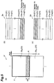
- the field of view F of the objective lens 25 is smaller than the sample S and, as illustrated in FIG 3 , a region in which an image can be acquired by onetime imaging becomes smaller than the sample S. Accordingly, in order to image the entire sample S, it is necessary for the field of view F of the objective lens 25 to be moved relative to the sample S.
- an image acquisition region 32 is set to include the sample S with respect to a sample container (for example, a glass slide) holding the sample S, and positions of a plurality of divided regions 33 are set based on the image acquisition region 32 and the field of view F of the objective lens 25 on the sample S.
- a portion of the sample S corresponding to a divided region 33 is imaged so as to acquire partial image data corresponding to the divided region 33, and then, if the field of view F of the objective lens 25 constitutes a position of the divided region 33 to be imaged next, imaging is performed again to acquire partial image data. Thereafter, in the image acquisition device 1, this operation is repeatedly executed, and the image processing unit 14 combines the acquired partial image data to form the entire image (combined image data) of the sample S.
- the stage driving unit 11 drives the stage 2 so that a position of the field of view F of the objective lens 25 relative to the sample S is moved in a scan direction along an imaging line Ln (n is a natural number) including a plurality of divided regions 33.
- an imaging line Ln (n is a natural number) including a plurality of divided regions 33.
- bidirectional scanning in which a scan direction is reversed between the adjacent imaging lines Ln is adopted, for example, as illustrated in FIG. 3 .
- unidirectional scanning in which the scan direction is the same direction between the adjacent imaging lines Ln may be employed.
- the direction along an imaging line Ln corresponds to the arrangement direction of the respective pixel rows 31 on the light reception surface 6a of the imaging element 6.
- the stage driving unit 11 drives the stage 2 at a velocity set based on the frame rate ⁇ of the imaging element 6. That is, the stage driving unit 11 drives the stage 2 at a velocity such that a timing at which the field of view F of the objective lens 25 constitutes the position of each divided region 33 matches a timing at which the imaging element 6 performs imaging.
- the stage driving unit 11 drives the stage 2, for example, at a velocity V shown in Equation (1) below based on the number M of pixel rows 31.
- V A ⁇ M ⁇ ⁇
- the stage driving unit 11 may drive, for example, the stage 2 at a velocity V expressed by Equation (2) below obtained by rewriting Equation (1).
- V H 1 ⁇ ⁇
- H1 denotes a length in a direction along an imaging line Ln of the field of view F of the objective lens 25.
- the objective lens driving unit 12 includes, for example, a motor such as a stepping motor (pulse motor) or an actuator such as a piezoelectric actuator, similar to the stage driving unit 11.
- the objective lens driving unit 12 drives the objective lens 25 in a Z direction along the optical axis of the objective lens 25. Accordingly, the focal position of the objective lens 25 relative to the sample S is moved.
- the light source control unit 13 causes the instantaneous light to be emitted from the light source 3, as illustrated in FIG 4 . That is, first, the imaging element 6 alternately performs exposure and reading, and outputs a trigger signal to the light source control unit 13 when all the pixel rows 31 (a first pixel row 31 1 , a second pixel row 31 2 , a third pixel row 31 3 , ..., an M-th pixel row 31 M ) are exposed.
- the light source control unit 13 causes the instantaneous light to be emitted from the light source 3 based on the trigger signal indicating that all the pixel rows 31 are exposed, which is output from the imaging element 6.
- W A / V
- the stage driving unit 11 driving the stage 2
- the position of the field of view F of the objective lens 25 relative to the sample S is moved, and the imaging element 6 which is a two-dimensional imaging element sequentially captures the optical image of the sample S at a predetermined frame rate ⁇ . Therefore, time for acquiring the partial images over the entire sample S is shortened. Further, in the image acquisition device 1, the stage driving unit 11 drives the stage 2 at a velocity based on the frame rate ⁇ of the imaging element 6.
- the light source control unit 13 causes the instantaneous light to be emitted from the light source 3 during a period of time in which all the pixel rows 31 are exposed, based on the trigger signal indicating that all the pixel rows 31 are exposed, which is output from the imaging element 6. Therefore, the partial images can be reliably acquired in all of the divided regions 33.
- the present invention is not limited to the above embodiment.
- the light source control unit 13 may cause the instantaneous light to be emitted from the light source 3 during the period of time in which all the pixel rows 31 are exposed, by setting a timing at which the instantaneous light is caused to emitted from the light source 3 to be synchronized with a timing at which the imaging element 6 performs imaging based on the frame rate ⁇ of the imaging element 6.
- the partial images can be reliably acquired in all of the divided regions 33.
- continuous light may be emitted from the light source 3 and a shutter may be provided between the light source 3 and the sample S.
- a light emitting means is configured with the light source 3 and the shutter, and the light source control unit 13 controls opening and closing of the shutter. Accordingly, the sample S can be irradiated with the instantaneous light during the period of time in which all the pixel rows 31 are exposed.
- a light guiding optical system driving unit driving unit that drives the light guiding optical system 5 including the objective lens 25 may be provided, and the position of the field of view of the objective lens 25 relative to the sample S may be moved by the light guiding optical system driving unit.
- the focal position of the objective lens 25 relative to the sample S is moved in the optical axis direction of the objective lens 25 by the objective lens driving unit 12 moving the objective lens 25 in the optical axis direction thereof in the above embodiment
- the focal position of the objective lens 25 relative to the sample S may be moved in the optical axis direction of the objective lens 25 by the stage driving unit 11 moving the stage 2 in the optical axis direction of the objective lens 25.
- stage driving unit 11 drives the stage 2 so that two divided regions 33 to be continuously captured come in contact with each other in the above embodiment, the stage driving unit 11 may drive the stage 2 so that the two divided regions 33 to be continuously captured partially overlap each other.
- the stage driving unit 11 may drive the stage 2 so that an overlapping region R in which a portion of the divided region 33 S and a portion of the divided regions 33 S+1 overlap each other is formed.
- the stage driving unit 11 can drive the stage 2 at a velocity V' shown in Equation (4) below, for example, based on the number N of pixel rows on the light reception surface 6a of the imaging element 6 corresponding to the overlapping region R.
- V ′ A ⁇ M ⁇ N ⁇ ⁇
- the stage driving unit 11 may drive the stage 2, for example, at a velocity V' shown in Equation (5) below obtained by rewriting Equation (4).
- V ′ H 1 ⁇ H 2 ⁇ ⁇
- H2 denotes a length of the overlapping region R in a direction along an imaging line Lt.
- the driving velocity of the stage 2 is set in consideration of the relationship between the overlapping region R and the the number N of pixel rows on the light reception surface 6a of the imaging element 6 corresponding to the overlapping region R, the overlapping region R is reliably formed. Accordingly, when the obtained partial images are combined, the partial images can be smoothly combined and an entire continuous image can be acquired.
- 1 image acquisition device
- 2 stage
- 3 light source (light emitting means)
- 5 light guiding optical system
- 6 imaging element
- 11 stage driving unit (driving unit)
- 12 objective lens driving unit
- 13 light source control unit (control unit)
- 14 image processing unit
- 22 microscope optical system
- 25 objective lens
- 31 pixel row
- 32 image acquisition region
- 33 divided region
- F field of view of objective lens
- R overlapping region
- S sample.
Abstract
Description
- The present invention relates to an image acquisition device and an image acquisition method for an image acquisition device.
- In an image acquisition device for acquiring a still image of a sample such as tissue cells, when the sample is larger than an imaging field of view of an imaging element, for example, partial images of the sample are sequentially acquired while a stage on which the sample is placed is being moved relative to the objective lens, and then, the partial images are combined so as to acquire an image of the entire sample.
- Conventionally, in such an image acquisition device, for example, an image acquisition method called a tile scan scheme is used. In the tile scan scheme, a stage is moved so that a predetermined region of the sample is included in the field of view of the objective lens, and then, the partial images are acquired using a two-dimensional imaging element such as a region sensor in a state in which the stage is caused to stop. Then, the same operation is repeatedly executed so as to acquire a still image of the entire sample.
- However, in the tile scan method, since partial images are acquired while repeatedly moving and stopping the stage, a long time taken to acquire the partial images over the entire sample is problematic. Accordingly, for example, in
Patent Literatures 1 to 3, an image acquisition method of acquiring partial images using a two-dimensional imaging element without stopping a stage has been proposed. More specifically, in the image acquisition method described inPatent Literature 1, the stage is moved, and a sample is intermittently irradiated with light in synchronization with the movement of the stage, and on the other hand, partial images are continuously acquired using a two-dimensional imaging element. -
- [Patent Literature 1]
Japanese Unexamined Patent Publication No. 2003-222801 - [Patent Literature 2]
Japanese Unexamined Patent Publication No. 2000-501844 - [Patent Literature 3]
Japanese Unexamined Patent Publication No. S63-191063 - However, for example, in the image acquisition method described in
Patent Literature 1, since the imaging element continues to acquire partial images during a period of time in which the sample is not irradiated with light, a large number of unnecessary images are included among the obtained partial images. Since it is necessary for the unnecessary images to be excluded when still images of the entire sample are combined, time required for combination of all images may increase due to a large number of unnecessary images being included. - The present invention has been made to solve the above problem, and an object thereof is to provide an image acquisition device and an image acquisition method for an image acquisition device capable of executing acquisition of partial images and combination of all images at high speed.
- In order to solve the above problem, an image acquisition device according to the present invention includes a stage on which a sample is placed; a light emitting means for emitting instantaneous light; a light guiding optical system including an objective lens arranged to face the sample on the stage; an imaging element for capturing an optical image of the sample guided by the light guiding optical system; a driving unit for moving a position of a field of view of the objective lens relative to the sample at a predetermined velocity; and a control unit for controlling the light emitting means, wherein the imaging element is a two-dimensional imaging element including a plurality of pixel rows and for sequentially capturing at a predetermined frame rate, and the velocity is a velocity set based on at least the frame rate.
- In this image acquisition device, the driving unit moves the position of the field of view of the objective lens relative to the sample at a predetermined velocity, and a two-dimensional imaging element sequentially captures an optical image of the sample at a predetermined frame rate. Therefore, time required for acquiring the partial images over the entire sample is shortened. Further, in the image acquisition device, the moving velocity of the position of the field of view is a velocity set based on the frame rate of the imaging element. Therefore, the movement of the position of the field of view and the imaging of the imaging element are synchronized with each other, and it is possible to capture only necessary partial images. Therefore, in this image acquisition device, the acquisition of the partial images and the combination of all the images can be executed at high speed.
- It is preferable for the predetermined velocity to be a velocity set based on at least the number of pixel rows of the imaging element. In this case, since a moving velocity of the position of the field of view is set in consideration of a relationship between the number of pixel rows of the imaging element and a region of the sample imaged through onetime imaging, it is possible to capture only necessary partial images more reliably.
- It is preferable for the predetermined velocity to be a velocity set based on at least the optical magnification of the light guiding optical system. In this case, since the moving velocity of the position of the field of view of the objective lens is set in consideration of a size of the field of view of the objective lens, it is possible to perform imaging at a desired position more reliably.
- It is preferable for the predetermined velocity to be a velocity set based on at least a pixel width of the pixel row of the imaging element In this case, since the moving velocity of the position of the field of view of the objective lens is set in consideration of a size of the field of view of the objective lens, it is possible to perform imaging at a desired position more reliably.
- It is preferable for the predetermined velocity to be a velocity set so that portions of two regions of the sample to be continuously captured by the imaging element overlap each other. In this case, since the portions of two regions of the sample to be continuously captured overlap each other, the obtained partial images can be smoothly combined when the partial images are combined, and an entire continuous image can be acquired.
- It is preferable for the predetermined velocity to be a velocity set based on the number of pixel rows of the imaging element corresponding to an overlapping region in which portions of the two regions overlap each other. In this case, since the moving velocity of the position of the field of view is set in consideration of a relationship between the overlapping region and the number of pixel rows of the imaging element corresponding to the overlapping region, the overlapping region is formed more reliably.
- It is preferable that the imaging element outputs a trigger signal indicating that all of the pixel rows are exposed, to the control unit, and the control unit causes the instantaneous light to be emitted from the light emitting means during a period of time in which all of the pixel rows are exposed, based on the trigger signal output from the imaging element. In this case, since the instantaneous light can be emitted during a period of time in which all of the pixel rows are reliably exposed, it is possible to reliably acquire each partial image.
- An image acquisition method for an image acquisition device according to the present invention is an image acquisition method for an image acquisition device including a stage on which a sample is placed, a light emitting means for emitting instantaneous light, a light guiding optical system including an objective lens arranged to face the sample on the stage, an imaging element for capturing an optical image of the sample guided by the light guiding optical system, a driving unit for moving a position of a field of view of the objective lens relative to the sample at a predetermined velocity, and a control unit for controlling the light emitting means, the image acquisition method comprising: using, as the imaging element, a two-dimensional imaging element including a plurality of pixel rows and for sequentially capturing at a predetermined frame rate, and the velocity is set based on at least the frame rate.
- In this image acquisition method for an image acquisition device, the driving unit moves the position of the field of view of the objective lens relative to the sample at a predetermined velocity, and a two-dimensional imaging element sequentially captures an optical image of the sample at a predetermined frame rate. Therefore, time required for acquiring the partial images over the entire sample is shortened. Further, in the image acquisition method for an image acquisition device, the moving velocity of the position of the field of view is set based on the frame rate of the imaging element. Therefore, the movement of the position of the field of view and the imaging of the imaging element are synchronized with each other, and it is possible to capture only necessary partial images. Therefore, in this image acquisition method for an image acquisition device, the acquisition of the partial images and the combination of all the images can be executed at high speed.
- It is preferable for the predetermined velocity to be set based on at least the number of pixel rows of the imaging element. In this case, since a moving velocity of the position of the field of view is set in consideration of a relationship between the number of pixel rows of the imaging element and a region of the sample imaged through onetime imaging, it is possible to capture only necessary partial images more reliably.
- It is preferable for the velocity to be set so that portions of two regions of the sample to be continuously captured by the imaging element overlap each other. In this case, since the portions of two regions of the sample to be continuously captured overlap each other, the obtained partial images can be smoothly combined when the partial images are combined, and an entire continuous image can be acquired.
- According to the present invention, the acquisition of the partial images and the combination of all the images can be executed at high speed.
-
-
FIG 1 is a diagram illustrating an embodiment of an image acquisition device according to the present invention. -
FIG 2 is a diagram illustrating a light reception surface of an imaging element constituting the image acquisition device illustrated inFIG. 1 . -
FIG 3 is a diagram illustrating an example of scan of an image acquisition region for a sample. -
FIG 4 is a diagram illustrating an example of a relationship between a period of time of exposure and a period of time of reading and irradiation of instantaneous light in the imaging element. -
FIGS. 5(a) to 5(c) are diagrams illustrating an example of a relationship between scan of an image acquisition region and a light reception surface of the imaging element according to a modification example. - Hereinafter, preferred embodiments of an image acquisition device according to the present invention will be described in detail with reference to the accompanying drawings.
-
FIG 1 is a diagram illustrating an embodiment of an image acquisition device according to the present invention. As illustrated inFIG 1 , animage acquisition device 1 includes astage 2 on which a sample S is placed, a light source 3 (light emitting means) that irradiates the sample with instantaneous light, a light guidingoptical system 5 including anobjective lens 25 arranged to face the sample S on thestage 2, and animaging element 6 that captures an optical image of the sample S guided by the light guidingoptical system 5. - Further, the
image acquisition device 1 includes a stage driving unit 11 (driving unit) that moves a position of a field of view of theobjective lens 25 relative to the sample S, an objectivelens driving unit 12 that changes a focal position of theobjective lens 25 relative to the sample S, a light source control unit 13 (control unit) that controls thelight source 3, and animage processing unit 14. - The sample S observed by the
image acquisition device 1 is, for example, a biological sample, such as tissue cells, and is placed on thestage 2 in a state in which the sample S is sealed on a glass slide. Thelight source 3 is arranged on the bottom side of thestage 2. For example, a laser diode (LD), a light emitting diode (LED), a super luminescent diode (SLD), a flash lamp light source such as a xenon flash lamp, or the like is used as thelight source 3. - The light guiding
optical system 5 includes an illuminationoptical system 21 arranged between thelight source 3 and thestage 2, and a microscopeoptical system 22 arranged between thestage 2 and theimaging element 6. The illuminationoptical system 21 includes, for example, a Koehler illumination optical system including acondenser lens 23 and aprojection lens 24, and guides light from thelight source 3 and irradiates the sample S with uniform light. - Meanwhile, the microscope
optical system 22 includes theobjective lens 25, and animage forming lens 26 arranged on the downstream side (imaging element 6 side) of theobjective lens 25, and guides an optical image of the sample S to theimaging element 6. The optical image of the sample S is an image formed by transmitted light in the case of bright field illumination, scattered light in the case of dark field illumination, or emitted light (fluorescence) in the case of emitted light measurement. Further, the optical image of the sample S may also be an image formed by reflected light from the sample S. In these cases, an optical system corresponding to image acquisition of the transmitted light image, the scattered light image, and the emitted light (fluorescence) image of the sample S can be adopted as the light guidingoptical system 5. - The
imaging element 6 is a two-dimensional imaging element having a plurality of pixel rows. Examples of such animaging element 6 may include a CCD image sensor or a CMOS image sensor. On alight reception surface 6a of theimaging element 6, for example, M pixel rows 31 (afirst pixel row 311, asecond pixel row 312, athird pixel row 313, ..., a (M-2)-th pixel row 31M-2, a (M-1)-th pixel row 31M-1, and an M-th pixel row 31M) in which a plurality of pixels are one-dimensionally arranged are arranged in parallel, as illustrated inFIG. 2 . A length (pixel width) P in an arrangement direction (reading direction) of eachpixel row 31 is, for example, about 1.5 µm. Theimaging element 6 sequentially captures an optical image of the sample S guided by the light guidingoptical system 5 at a predetermined frame rate α (for example, less than 30 frames per second (fps)). - The
stage driving unit 11 includes, for example, a motor such as a stepping motor (pulse motor) or an actuator such as a piezoelectric actuator. Thestage driving unit 11 drives thestage 2 in an XY direction relative to a surface having a predetermined angle (for example, 90°) with respect to a plane perpendicular to an optical axis of theobjective lens 25. Accordingly, the sample S fixed to thestage 2 is moved relative to the optical axis of the objective lens, and a position of the field of view of theobjective lens 25 relative to the sample S is moved. - In the
image acquisition device 1, imaging of the sample S is performed at a high magnification such as 20x or 40x. Therefore, the field of view F of theobjective lens 25 is smaller than the sample S and, as illustrated inFIG 3 , a region in which an image can be acquired by onetime imaging becomes smaller than the sample S. Accordingly, in order to image the entire sample S, it is necessary for the field of view F of theobjective lens 25 to be moved relative to the sample S. - Therefore, in the
image acquisition device 1, animage acquisition region 32 is set to include the sample S with respect to a sample container (for example, a glass slide) holding the sample S, and positions of a plurality of dividedregions 33 are set based on theimage acquisition region 32 and the field of view F of theobjective lens 25 on the sample S. A portion of the sample S corresponding to a dividedregion 33 is imaged so as to acquire partial image data corresponding to the dividedregion 33, and then, if the field of view F of theobjective lens 25 constitutes a position of the dividedregion 33 to be imaged next, imaging is performed again to acquire partial image data. Thereafter, in theimage acquisition device 1, this operation is repeatedly executed, and theimage processing unit 14 combines the acquired partial image data to form the entire image (combined image data) of the sample S. - In this case, the
stage driving unit 11 drives thestage 2 so that a position of the field of view F of theobjective lens 25 relative to the sample S is moved in a scan direction along an imaging line Ln (n is a natural number) including a plurality of dividedregions 33. For the movement of the position of the field of view of theobjective lens 25 relative to the sample S between adjacent imaging lines Ln, bidirectional scanning in which a scan direction is reversed between the adjacent imaging lines Ln is adopted, for example, as illustrated inFIG. 3 . Further, unidirectional scanning in which the scan direction is the same direction between the adjacent imaging lines Ln may be employed. The direction along an imaging line Ln corresponds to the arrangement direction of therespective pixel rows 31 on thelight reception surface 6a of theimaging element 6. - Further, the
stage driving unit 11 drives thestage 2 at a velocity set based on the frame rate α of theimaging element 6. That is, thestage driving unit 11 drives thestage 2 at a velocity such that a timing at which the field of view F of theobjective lens 25 constitutes the position of each dividedregion 33 matches a timing at which theimaging element 6 performs imaging. - Specifically, the
stage driving unit 11 drives thestage 2, for example, at a velocity V shown in Equation (1) below based on the number M ofpixel rows 31.
pixel rows 31/optical magnification of the microscope optical system 22). - Further, the
stage driving unit 11 may drive, for example, thestage 2 at a velocity V expressed by Equation (2) below obtained by rewriting Equation (1).
objective lens 25. - The objective
lens driving unit 12 includes, for example, a motor such as a stepping motor (pulse motor) or an actuator such as a piezoelectric actuator, similar to thestage driving unit 11. The objectivelens driving unit 12 drives theobjective lens 25 in a Z direction along the optical axis of theobjective lens 25. Accordingly, the focal position of theobjective lens 25 relative to the sample S is moved. - The light
source control unit 13 causes the instantaneous light to be emitted from thelight source 3, as illustrated inFIG 4 . That is, first, theimaging element 6 alternately performs exposure and reading, and outputs a trigger signal to the lightsource control unit 13 when all the pixel rows 31 (afirst pixel row 311, asecond pixel row 312, athird pixel row 313, ..., an M-th pixel row 31M) are exposed. - Subsequently, the light
source control unit 13 causes the instantaneous light to be emitted from thelight source 3 based on the trigger signal indicating that all thepixel rows 31 are exposed, which is output from theimaging element 6. The instantaneous light has, for example, a pulse width W shown in Equation (3) below.
pixel rows 31. Therefore, it becomes possible to obtain a still image of which the distortion is suppressed. Thereafter, in theimage acquisition device 1, the above-described operation is repeatedly performed. - As described above, in the
image acquisition device 1, by thestage driving unit 11 driving thestage 2, the position of the field of view F of theobjective lens 25 relative to the sample S is moved, and theimaging element 6 which is a two-dimensional imaging element sequentially captures the optical image of the sample S at a predetermined frame rate α. Therefore, time for acquiring the partial images over the entire sample S is shortened. Further, in theimage acquisition device 1, thestage driving unit 11 drives thestage 2 at a velocity based on the frame rate α of theimaging element 6. Therefore, driving of the stage 2 (movement of the position of the field of view F of the objective lens 25) and imaging of theimaging element 6 are synchronized with each other so that a timing at which a field of view F of theobjective lens 25 constitutes the position of each dividedregion 33 matches a timing at which theimaging element 6 performs imaging. Accordingly, it is possible to capture only the partial image corresponding to each dividedregion 33. Therefore, in theimage acquisition device 1, the acquisition of the partial images and the combination of all the images can be executed at high speed. - Further, the light
source control unit 13 causes the instantaneous light to be emitted from thelight source 3 during a period of time in which all thepixel rows 31 are exposed, based on the trigger signal indicating that all thepixel rows 31 are exposed, which is output from theimaging element 6. Therefore, the partial images can be reliably acquired in all of the dividedregions 33. - The present invention is not limited to the above embodiment. For example, while the light
source control unit 13 causes the instantaneous light to be emitted from thelight source 3 based on the trigger signal output from theimaging element 6 in the above embodiment, the lightsource control unit 13 may cause the instantaneous light to be emitted from thelight source 3 during the period of time in which all thepixel rows 31 are exposed, by setting a timing at which the instantaneous light is caused to emitted from thelight source 3 to be synchronized with a timing at which theimaging element 6 performs imaging based on the frame rate α of theimaging element 6. In this case, the partial images can be reliably acquired in all of the dividedregions 33. - Further, while the instantaneous light is emitted from the
light source 3 in the above embodiment, continuous light (CW light) may be emitted from thelight source 3 and a shutter may be provided between thelight source 3 and the sample S. In this case, a light emitting means is configured with thelight source 3 and the shutter, and the lightsource control unit 13 controls opening and closing of the shutter. Accordingly, the sample S can be irradiated with the instantaneous light during the period of time in which all thepixel rows 31 are exposed. - Further, while the position of the field of view of the
objective lens 25 relative to the sample S is moved by thestage driving unit 11 driving thestage 2 in the above embodiment, a light guiding optical system driving unit (driving unit) that drives the light guidingoptical system 5 including theobjective lens 25 may be provided, and the position of the field of view of theobjective lens 25 relative to the sample S may be moved by the light guiding optical system driving unit. - Further, while the focal position of the
objective lens 25 relative to the sample S is moved in the optical axis direction of theobjective lens 25 by the objectivelens driving unit 12 moving theobjective lens 25 in the optical axis direction thereof in the above embodiment, the focal position of theobjective lens 25 relative to the sample S may be moved in the optical axis direction of theobjective lens 25 by thestage driving unit 11 moving thestage 2 in the optical axis direction of theobjective lens 25. - Further, while the
stage driving unit 11 drives thestage 2 so that two dividedregions 33 to be continuously captured come in contact with each other in the above embodiment, thestage driving unit 11 may drive thestage 2 so that the two dividedregions 33 to be continuously captured partially overlap each other. - That is, as illustrated in
FIG 5(a) , when a dividedregion 33S+1 following a dividedregion 33S in an imaging line Lt (t is a natural number equal to or greater than 1 and smaller than or equal to n) is imaged by theimaging element 6, thestage driving unit 11 may drive thestage 2 so that an overlapping region R in which a portion of the dividedregion 33S and a portion of the dividedregions 33S+1 overlap each other is formed. - Specifically, the
stage driving unit 11 can drive thestage 2 at a velocity V' shown in Equation (4) below, for example, based on the number N of pixel rows on thelight reception surface 6a of theimaging element 6 corresponding to the overlapping region R.
- In this case, when the field of view F of the
objective lens 25 constitutes a position of the dividedregion 33S, for example, an (M-1)-th pixel row 31M-1 and an M-th pixel row 31M on thelight reception surface 6a of theimaging element 6 correspond to the overlapping region R, as illustrated inFIG 5(b) . On the other hand, when the field of view F of theobjective lens 25 constitutes a position of the dividedregion 33S+1, for example, afirst pixel row 311 and asecond pixel row 312 on thelight reception surface 6a of theimaging element 6 correspond to the overlapping region R, as illustrated inFIG 5(c) . - As described above, the
stage driving unit 11 drives thestage 2 at a velocity V' shown in Equation (4) based on the number N of pixel rows (N = 2 in the example illustrated inFIGS. 5(a) to 5(c) ) on thelight reception surface 6a of theimaging element 6 corresponding to the overlapping region R. In this case, thestage driving unit 11 may drive thestage 2, for example, at a velocity V' shown in Equation (5) below obtained by rewriting Equation (4).
- In this case, since the driving velocity of the
stage 2 is set in consideration of the relationship between the overlapping region R and the the number N of pixel rows on thelight reception surface 6a of theimaging element 6 corresponding to the overlapping region R, the overlapping region R is reliably formed. Accordingly, when the obtained partial images are combined, the partial images can be smoothly combined and an entire continuous image can be acquired. - 1: image acquisition device, 2: stage, 3: light source (light emitting means), 5: light guiding optical system, 6: imaging element, 11: stage driving unit (driving unit), 12: objective lens driving unit, 13: light source control unit (control unit), 14: image processing unit, 22: microscope optical system, 25: objective lens, 31: pixel row, 32: image acquisition region, 33: divided region, F: field of view of objective lens, R: overlapping region, S: sample.
Claims (10)
- An image acquisition device, comprising:a stage on which a sample is placed;a light emitting means for emitting instantaneous light;a light guiding optical system including an objective lens arranged to face the sample on the stage;an imaging element for capturing an optical image of the sample guided by the light guiding optical system;a driving unit for moving a position of a field of view of the objective lens relative to the sample at a predetermined velocity; anda control unit for controlling the light emitting means,wherein the imaging element is a two-dimensional imaging element including a plurality of pixel rows and for sequentially capturing at a predetermined frame rate, andthe velocity is a velocity set based on at least the frame rate.
- The image acquisition device according to claim 1,
wherein the velocity is a velocity set based on at least the number of pixel rows of the imaging element. - The image acquisition device according to claim 1 or 2,
wherein the velocity is a velocity set based on at least optical magnification of the light guiding optical system. - The image acquisition device according to any one of claims 1 to 3,
wherein the velocity is a velocity set based on at least a pixel width of the pixel row of the imaging element. - The image acquisition device according to any one of claims 1 to 4,
wherein the velocity is a velocity set so that portions of two regions of the sample to be continuously captured by the imaging element overlap each other. - The image acquisition device according to claim 5,
wherein the velocity is a velocity set based on the number of pixel rows of the imaging element corresponding to an overlapping region in which portions of the two regions overlap each other. - The image acquisition device according to any one of claims 1 to 6,
wherein the imaging element outputs a trigger signal indicating that all of the pixel rows are exposed, to the control unit, and
the control unit causes the instantaneous light to be emitted from the light emitting means during a period of time in which all of the pixel rows are exposed, based on the trigger signal output from the imaging element. - An image acquisition method for an image acquisition device comprising:a stage on which a sample is placed,a light emitting means for emitting instantaneous light,a light guiding optical system including an objective lens arranged to face the sample on the stage,an imaging element for capturing an optical image of the sample guided by the light guiding optical system,a driving unit for moving a position of a field of view of the objective lens relative to the sample at a predetermined velocity, anda control unit for controlling the light emitting means, the image acquisition method comprising:using, as the imaging element, a two-dimensional imaging element including a plurality of pixel rows and for sequentially capturing at a predetermined frame rate, andsetting the velocity based on at least the frame rate.
- The image acquisition method for an image acquisition device according to claim 8,
wherein setting the velocity based on at least the number of pixel rows of the imaging element. - The image acquisition method for an image acquisition device according to claim 8 or 9,
wherein setting the velocity so that portions of two regions of the sample to be continuously captured by the imaging element overlap each other.
Applications Claiming Priority (2)
| Application Number | Priority Date | Filing Date | Title |
|---|---|---|---|
| JP2013228560A JP6154291B2 (en) | 2013-11-01 | 2013-11-01 | Image acquisition device and image acquisition method of image acquisition device |
| PCT/JP2014/051804 WO2015064116A1 (en) | 2013-11-01 | 2014-01-28 | Image acquisition device and image acquisition method for image acquisition device |
Publications (3)
| Publication Number | Publication Date |
|---|---|
| EP3064981A1 true EP3064981A1 (en) | 2016-09-07 |
| EP3064981A4 EP3064981A4 (en) | 2017-04-05 |
| EP3064981B1 EP3064981B1 (en) | 2022-04-20 |
Family
ID=53003740
Family Applications (1)
| Application Number | Title | Priority Date | Filing Date |
|---|---|---|---|
| EP14856848.8A Active EP3064981B1 (en) | 2013-11-01 | 2014-01-28 | Image acquisition device and image acquisition method for image acquisition device |
Country Status (7)
| Country | Link |
|---|---|
| US (1) | US9911028B2 (en) |
| EP (1) | EP3064981B1 (en) |
| JP (1) | JP6154291B2 (en) |
| CN (1) | CN105683805B (en) |
| DK (1) | DK3064981T3 (en) |
| HU (1) | HUE059480T2 (en) |
| WO (1) | WO2015064116A1 (en) |
Cited By (1)
| Publication number | Priority date | Publication date | Assignee | Title |
|---|---|---|---|---|
| EP3572798A1 (en) * | 2018-05-23 | 2019-11-27 | Commissariat à l'Énergie Atomique et aux Énergies Alternatives | Device and method for observing a fluorescent sample by defocused imaging |
Families Citing this family (8)
| Publication number | Priority date | Publication date | Assignee | Title |
|---|---|---|---|---|
| JP6698451B2 (en) * | 2016-07-11 | 2020-05-27 | オリンパス株式会社 | Observation device |
| CN107782738A (en) * | 2016-08-31 | 2018-03-09 | 上海微电子装备(集团)股份有限公司 | A kind of automatic optical detection device and its detection method |
| JP6865010B2 (en) * | 2016-10-19 | 2021-04-28 | オリンパス株式会社 | Microscope system and specimen observation method |
| JP6842387B2 (en) * | 2017-08-31 | 2021-03-17 | 浜松ホトニクス株式会社 | Image acquisition device and image acquisition method |
| JP7023659B2 (en) * | 2017-09-29 | 2022-02-22 | キヤノン株式会社 | Imaging device, imaging system, mobile body |
| JP6920978B2 (en) * | 2017-12-18 | 2021-08-18 | 浜松ホトニクス株式会社 | Image acquisition device and image acquisition method |
| CN109752916A (en) * | 2018-12-26 | 2019-05-14 | 江苏大学 | A kind of planar laser filming apparatus and its method |
| KR102596730B1 (en) * | 2022-02-16 | 2023-11-02 | 주식회사 팍스웰 | Lenseless Optical System |
Citations (3)
| Publication number | Priority date | Publication date | Assignee | Title |
|---|---|---|---|---|
| WO1997004347A1 (en) * | 1995-07-19 | 1997-02-06 | Morphometrix Technologies Inc. | Automated scanning of microscope slides |
| EP1324097A2 (en) * | 2001-12-18 | 2003-07-02 | Fairfield Imaging Ltd. | Method and apparatus for acquiring digital microscope images |
| EP1439385A1 (en) * | 2003-01-15 | 2004-07-21 | Negevtech Ltd. | Method and system for fast on-line electro-optical detection of wafer defects |
Family Cites Families (12)
| Publication number | Priority date | Publication date | Assignee | Title |
|---|---|---|---|---|
| JPS63191063A (en) | 1987-02-03 | 1988-08-08 | Sumitomo Electric Ind Ltd | System for processing microscopic image |
| JPH09281405A (en) * | 1996-04-17 | 1997-10-31 | Olympus Optical Co Ltd | Microscopic system |
| JPH11326233A (en) * | 1998-05-12 | 1999-11-26 | Mitsui Mining & Smelting Co Ltd | Apparatus for inspecting material surface |
| JP2003222801A (en) * | 2002-01-29 | 2003-08-08 | Olympus Optical Co Ltd | Microscopic image photographing device |
| JP4102842B1 (en) * | 2006-12-04 | 2008-06-18 | 東京エレクトロン株式会社 | Defect detection device, defect detection method, information processing device, information processing method, and program thereof |
| JP5289756B2 (en) * | 2007-11-26 | 2013-09-11 | オリンパス株式会社 | Microscope observation system |
| JP2010002534A (en) * | 2008-06-19 | 2010-01-07 | Nikon Corp | Microscope device |
| JP5290053B2 (en) * | 2009-05-21 | 2013-09-18 | オリンパス株式会社 | Microscope system |
| JP5365407B2 (en) | 2009-08-17 | 2013-12-11 | ソニー株式会社 | Image acquisition apparatus and image acquisition method |
| CN102854615B (en) * | 2012-04-27 | 2015-07-22 | 麦克奥迪实业集团有限公司 | Full-automatic scanning system and method for microscopic section |
| JP2014026233A (en) * | 2012-07-30 | 2014-02-06 | Olympus Corp | Imaging system |
| WO2014127468A1 (en) * | 2013-02-25 | 2014-08-28 | Huron Technologies International Inc. | Microscopy slide scanner with variable magnification |
-
2013
- 2013-11-01 JP JP2013228560A patent/JP6154291B2/en active Active
-
2014
- 2014-01-28 EP EP14856848.8A patent/EP3064981B1/en active Active
- 2014-01-28 CN CN201480058554.5A patent/CN105683805B/en active Active
- 2014-01-28 HU HUE14856848A patent/HUE059480T2/en unknown
- 2014-01-28 DK DK14856848.8T patent/DK3064981T3/en active
- 2014-01-28 US US15/031,083 patent/US9911028B2/en active Active
- 2014-01-28 WO PCT/JP2014/051804 patent/WO2015064116A1/en active Application Filing
Patent Citations (3)
| Publication number | Priority date | Publication date | Assignee | Title |
|---|---|---|---|---|
| WO1997004347A1 (en) * | 1995-07-19 | 1997-02-06 | Morphometrix Technologies Inc. | Automated scanning of microscope slides |
| EP1324097A2 (en) * | 2001-12-18 | 2003-07-02 | Fairfield Imaging Ltd. | Method and apparatus for acquiring digital microscope images |
| EP1439385A1 (en) * | 2003-01-15 | 2004-07-21 | Negevtech Ltd. | Method and system for fast on-line electro-optical detection of wafer defects |
Non-Patent Citations (1)
| Title |
|---|
| See also references of WO2015064116A1 * |
Cited By (2)
| Publication number | Priority date | Publication date | Assignee | Title |
|---|---|---|---|---|
| EP3572798A1 (en) * | 2018-05-23 | 2019-11-27 | Commissariat à l'Énergie Atomique et aux Énergies Alternatives | Device and method for observing a fluorescent sample by defocused imaging |
| WO2019224474A1 (en) * | 2018-05-23 | 2019-11-28 | Commissariat à l'énergie atomique et aux énergies alternatives | Apparatus and method for examining a fluorescent sample using unfocused imaging |
Also Published As
| Publication number | Publication date |
|---|---|
| JP2015087719A (en) | 2015-05-07 |
| CN105683805B (en) | 2018-09-28 |
| JP6154291B2 (en) | 2017-06-28 |
| US9911028B2 (en) | 2018-03-06 |
| HUE059480T2 (en) | 2022-11-28 |
| DK3064981T3 (en) | 2022-06-13 |
| WO2015064116A1 (en) | 2015-05-07 |
| EP3064981B1 (en) | 2022-04-20 |
| EP3064981A4 (en) | 2017-04-05 |
| US20160267317A1 (en) | 2016-09-15 |
| CN105683805A (en) | 2016-06-15 |
Similar Documents
| Publication | Publication Date | Title |
|---|---|---|
| EP3064981A1 (en) | Image acquisition device and image acquisition method for image acquisition device | |
| US10602087B2 (en) | Image acquisition device, and imaging device | |
| US9667858B2 (en) | Image acquisition device and image acquisition device focusing method | |
| EP3064982B1 (en) | Image acquisition device and image acquisition method for image acquisition device | |
| CN111033352B (en) | Image acquisition device and image acquisition method | |
| JP6496772B2 (en) | Image acquisition apparatus and image acquisition method | |
| EP2947488B1 (en) | Image acquisition device and focus method for image acquisition device | |
| JP2010271604A (en) | Imaging device | |
| JP2015159541A (en) | Image acquisition device and imaging device | |
| JP6240056B2 (en) | Image acquisition apparatus and imaging apparatus | |
| JP2013025023A (en) | Virtual slide device | |
| JP2018050318A (en) | Image acquisition device, imaging device, and calculation device |
Legal Events
| Date | Code | Title | Description |
|---|---|---|---|
| PUAI | Public reference made under article 153(3) epc to a published international application that has entered the european phase |
Free format text: ORIGINAL CODE: 0009012 |
|
| 17P | Request for examination filed |
Effective date: 20160510 |
|
| AK | Designated contracting states |
Kind code of ref document: A1 Designated state(s): AL AT BE BG CH CY CZ DE DK EE ES FI FR GB GR HR HU IE IS IT LI LT LU LV MC MK MT NL NO PL PT RO RS SE SI SK SM TR |
|
| AX | Request for extension of the european patent |
Extension state: BA ME |
|
| DAX | Request for extension of the european patent (deleted) | ||
| A4 | Supplementary search report drawn up and despatched |
Effective date: 20170302 |
|
| RIC1 | Information provided on ipc code assigned before grant |
Ipc: G02B 21/36 20060101AFI20170224BHEP Ipc: H04N 5/225 20060101ALI20170224BHEP |
|
| STAA | Information on the status of an ep patent application or granted ep patent |
Free format text: STATUS: EXAMINATION IS IN PROGRESS |
|
| RIC1 | Information provided on ipc code assigned before grant |
Ipc: H04N 5/225 20060101ALI20191203BHEP Ipc: G02B 21/36 20060101AFI20191203BHEP Ipc: G02B 21/08 20060101ALI20191203BHEP |
|
| 17Q | First examination report despatched |
Effective date: 20191211 |
|
| STAA | Information on the status of an ep patent application or granted ep patent |
Free format text: STATUS: EXAMINATION IS IN PROGRESS |
|
| GRAP | Despatch of communication of intention to grant a patent |
Free format text: ORIGINAL CODE: EPIDOSNIGR1 |
|
| STAA | Information on the status of an ep patent application or granted ep patent |
Free format text: STATUS: GRANT OF PATENT IS INTENDED |
|
| INTG | Intention to grant announced |
Effective date: 20220121 |
|
| GRAS | Grant fee paid |
Free format text: ORIGINAL CODE: EPIDOSNIGR3 |
|
| GRAA | (expected) grant |
Free format text: ORIGINAL CODE: 0009210 |
|
| STAA | Information on the status of an ep patent application or granted ep patent |
Free format text: STATUS: THE PATENT HAS BEEN GRANTED |
|
| AK | Designated contracting states |
Kind code of ref document: B1 Designated state(s): AL AT BE BG CH CY CZ DE DK EE ES FI FR GB GR HR HU IE IS IT LI LT LU LV MC MK MT NL NO PL PT RO RS SE SI SK SM TR |
|
| REG | Reference to a national code |
Ref country code: GB Ref legal event code: FG4D |
|
| REG | Reference to a national code |
Ref country code: CH Ref legal event code: EP |
|
| REG | Reference to a national code |
Ref country code: DE Ref legal event code: R096 Ref document number: 602014083364 Country of ref document: DE |
|
| REG | Reference to a national code |
Ref country code: IE Ref legal event code: FG4D |
|
| REG | Reference to a national code |
Ref country code: AT Ref legal event code: REF Ref document number: 1485615 Country of ref document: AT Kind code of ref document: T Effective date: 20220515 |
|
| REG | Reference to a national code |
Ref country code: DK Ref legal event code: T3 Effective date: 20220609 |
|
| REG | Reference to a national code |
Ref country code: SE Ref legal event code: TRGR |
|
| REG | Reference to a national code |
Ref country code: LT Ref legal event code: MG9D |
|
| REG | Reference to a national code |
Ref country code: NL Ref legal event code: MP Effective date: 20220420 |
|
| REG | Reference to a national code |
Ref country code: AT Ref legal event code: MK05 Ref document number: 1485615 Country of ref document: AT Kind code of ref document: T Effective date: 20220420 |
|
| PG25 | Lapsed in a contracting state [announced via postgrant information from national office to epo] |
Ref country code: NL Free format text: LAPSE BECAUSE OF FAILURE TO SUBMIT A TRANSLATION OF THE DESCRIPTION OR TO PAY THE FEE WITHIN THE PRESCRIBED TIME-LIMIT Effective date: 20220420 |
|
| PG25 | Lapsed in a contracting state [announced via postgrant information from national office to epo] |
Ref country code: PT Free format text: LAPSE BECAUSE OF FAILURE TO SUBMIT A TRANSLATION OF THE DESCRIPTION OR TO PAY THE FEE WITHIN THE PRESCRIBED TIME-LIMIT Effective date: 20220822 Ref country code: NO Free format text: LAPSE BECAUSE OF FAILURE TO SUBMIT A TRANSLATION OF THE DESCRIPTION OR TO PAY THE FEE WITHIN THE PRESCRIBED TIME-LIMIT Effective date: 20220720 Ref country code: LT Free format text: LAPSE BECAUSE OF FAILURE TO SUBMIT A TRANSLATION OF THE DESCRIPTION OR TO PAY THE FEE WITHIN THE PRESCRIBED TIME-LIMIT Effective date: 20220420 Ref country code: HR Free format text: LAPSE BECAUSE OF FAILURE TO SUBMIT A TRANSLATION OF THE DESCRIPTION OR TO PAY THE FEE WITHIN THE PRESCRIBED TIME-LIMIT Effective date: 20220420 Ref country code: GR Free format text: LAPSE BECAUSE OF FAILURE TO SUBMIT A TRANSLATION OF THE DESCRIPTION OR TO PAY THE FEE WITHIN THE PRESCRIBED TIME-LIMIT Effective date: 20220721 Ref country code: FI Free format text: LAPSE BECAUSE OF FAILURE TO SUBMIT A TRANSLATION OF THE DESCRIPTION OR TO PAY THE FEE WITHIN THE PRESCRIBED TIME-LIMIT Effective date: 20220420 Ref country code: ES Free format text: LAPSE BECAUSE OF FAILURE TO SUBMIT A TRANSLATION OF THE DESCRIPTION OR TO PAY THE FEE WITHIN THE PRESCRIBED TIME-LIMIT Effective date: 20220420 Ref country code: BG Free format text: LAPSE BECAUSE OF FAILURE TO SUBMIT A TRANSLATION OF THE DESCRIPTION OR TO PAY THE FEE WITHIN THE PRESCRIBED TIME-LIMIT Effective date: 20220720 Ref country code: AT Free format text: LAPSE BECAUSE OF FAILURE TO SUBMIT A TRANSLATION OF THE DESCRIPTION OR TO PAY THE FEE WITHIN THE PRESCRIBED TIME-LIMIT Effective date: 20220420 |
|
| REG | Reference to a national code |
Ref country code: HU Ref legal event code: AG4A Ref document number: E059480 Country of ref document: HU |
|
| PG25 | Lapsed in a contracting state [announced via postgrant information from national office to epo] |
Ref country code: RS Free format text: LAPSE BECAUSE OF FAILURE TO SUBMIT A TRANSLATION OF THE DESCRIPTION OR TO PAY THE FEE WITHIN THE PRESCRIBED TIME-LIMIT Effective date: 20220420 Ref country code: PL Free format text: LAPSE BECAUSE OF FAILURE TO SUBMIT A TRANSLATION OF THE DESCRIPTION OR TO PAY THE FEE WITHIN THE PRESCRIBED TIME-LIMIT Effective date: 20220420 Ref country code: LV Free format text: LAPSE BECAUSE OF FAILURE TO SUBMIT A TRANSLATION OF THE DESCRIPTION OR TO PAY THE FEE WITHIN THE PRESCRIBED TIME-LIMIT Effective date: 20220420 Ref country code: IS Free format text: LAPSE BECAUSE OF FAILURE TO SUBMIT A TRANSLATION OF THE DESCRIPTION OR TO PAY THE FEE WITHIN THE PRESCRIBED TIME-LIMIT Effective date: 20220820 |
|
| REG | Reference to a national code |
Ref country code: DE Ref legal event code: R097 Ref document number: 602014083364 Country of ref document: DE |
|
| PG25 | Lapsed in a contracting state [announced via postgrant information from national office to epo] |
Ref country code: SM Free format text: LAPSE BECAUSE OF FAILURE TO SUBMIT A TRANSLATION OF THE DESCRIPTION OR TO PAY THE FEE WITHIN THE PRESCRIBED TIME-LIMIT Effective date: 20220420 Ref country code: SK Free format text: LAPSE BECAUSE OF FAILURE TO SUBMIT A TRANSLATION OF THE DESCRIPTION OR TO PAY THE FEE WITHIN THE PRESCRIBED TIME-LIMIT Effective date: 20220420 Ref country code: RO Free format text: LAPSE BECAUSE OF FAILURE TO SUBMIT A TRANSLATION OF THE DESCRIPTION OR TO PAY THE FEE WITHIN THE PRESCRIBED TIME-LIMIT Effective date: 20220420 Ref country code: EE Free format text: LAPSE BECAUSE OF FAILURE TO SUBMIT A TRANSLATION OF THE DESCRIPTION OR TO PAY THE FEE WITHIN THE PRESCRIBED TIME-LIMIT Effective date: 20220420 Ref country code: CZ Free format text: LAPSE BECAUSE OF FAILURE TO SUBMIT A TRANSLATION OF THE DESCRIPTION OR TO PAY THE FEE WITHIN THE PRESCRIBED TIME-LIMIT Effective date: 20220420 |
|
| PLBE | No opposition filed within time limit |
Free format text: ORIGINAL CODE: 0009261 |
|
| STAA | Information on the status of an ep patent application or granted ep patent |
Free format text: STATUS: NO OPPOSITION FILED WITHIN TIME LIMIT |
|
| 26N | No opposition filed |
Effective date: 20230123 |
|
| PG25 | Lapsed in a contracting state [announced via postgrant information from national office to epo] |
Ref country code: AL Free format text: LAPSE BECAUSE OF FAILURE TO SUBMIT A TRANSLATION OF THE DESCRIPTION OR TO PAY THE FEE WITHIN THE PRESCRIBED TIME-LIMIT Effective date: 20220420 |
|
| PGFP | Annual fee paid to national office [announced via postgrant information from national office to epo] |
Ref country code: DK Payment date: 20230111 Year of fee payment: 10 |
|
| PG25 | Lapsed in a contracting state [announced via postgrant information from national office to epo] |
Ref country code: SI Free format text: LAPSE BECAUSE OF FAILURE TO SUBMIT A TRANSLATION OF THE DESCRIPTION OR TO PAY THE FEE WITHIN THE PRESCRIBED TIME-LIMIT Effective date: 20220420 |
|
| PGFP | Annual fee paid to national office [announced via postgrant information from national office to epo] |
Ref country code: HU Payment date: 20221212 Year of fee payment: 10 Ref country code: DE Payment date: 20221207 Year of fee payment: 10 |
|
| P01 | Opt-out of the competence of the unified patent court (upc) registered |
Effective date: 20230509 |
|
| REG | Reference to a national code |
Ref country code: CH Ref legal event code: PL |
|
| PG25 | Lapsed in a contracting state [announced via postgrant information from national office to epo] |
Ref country code: LU Free format text: LAPSE BECAUSE OF NON-PAYMENT OF DUE FEES Effective date: 20230128 |
|
| REG | Reference to a national code |
Ref country code: BE Ref legal event code: MM Effective date: 20230131 |
|
| PG25 | Lapsed in a contracting state [announced via postgrant information from national office to epo] |
Ref country code: LI Free format text: LAPSE BECAUSE OF NON-PAYMENT OF DUE FEES Effective date: 20230131 Ref country code: CH Free format text: LAPSE BECAUSE OF NON-PAYMENT OF DUE FEES Effective date: 20230131 |
|
| PG25 | Lapsed in a contracting state [announced via postgrant information from national office to epo] |
Ref country code: BE Free format text: LAPSE BECAUSE OF NON-PAYMENT OF DUE FEES Effective date: 20230131 |
|
| PGFP | Annual fee paid to national office [announced via postgrant information from national office to epo] |
Ref country code: GB Payment date: 20231207 Year of fee payment: 11 |
|
| PG25 | Lapsed in a contracting state [announced via postgrant information from national office to epo] |
Ref country code: IT Free format text: LAPSE BECAUSE OF FAILURE TO SUBMIT A TRANSLATION OF THE DESCRIPTION OR TO PAY THE FEE WITHIN THE PRESCRIBED TIME-LIMIT Effective date: 20220420 Ref country code: IE Free format text: LAPSE BECAUSE OF NON-PAYMENT OF DUE FEES Effective date: 20230128 |
|
| PGFP | Annual fee paid to national office [announced via postgrant information from national office to epo] |
Ref country code: SE Payment date: 20231213 Year of fee payment: 11 Ref country code: FR Payment date: 20231212 Year of fee payment: 11 |