EP3064981B1 - Image acquisition device and image acquisition method for image acquisition device - Google Patents
Image acquisition device and image acquisition method for image acquisition device Download PDFInfo
- Publication number
- EP3064981B1 EP3064981B1 EP14856848.8A EP14856848A EP3064981B1 EP 3064981 B1 EP3064981 B1 EP 3064981B1 EP 14856848 A EP14856848 A EP 14856848A EP 3064981 B1 EP3064981 B1 EP 3064981B1
- Authority
- EP
- European Patent Office
- Prior art keywords
- imaging element
- sample
- objective lens
- light
- image acquisition
- Prior art date
- Legal status (The legal status is an assumption and is not a legal conclusion. Google has not performed a legal analysis and makes no representation as to the accuracy of the status listed.)
- Active
Links
Images

Classifications
-
- G—PHYSICS
- G06—COMPUTING OR CALCULATING; COUNTING
- G06V—IMAGE OR VIDEO RECOGNITION OR UNDERSTANDING
- G06V20/00—Scenes; Scene-specific elements
- G06V20/60—Type of objects
- G06V20/69—Microscopic objects, e.g. biological cells or cellular parts
- G06V20/693—Acquisition
-
- G—PHYSICS
- G02—OPTICS
- G02B—OPTICAL ELEMENTS, SYSTEMS OR APPARATUS
- G02B21/00—Microscopes
- G02B21/36—Microscopes arranged for photographic purposes or projection purposes or digital imaging or video purposes including associated control and data processing arrangements
- G02B21/365—Control or image processing arrangements for digital or video microscopes
- G02B21/367—Control or image processing arrangements for digital or video microscopes providing an output produced by processing a plurality of individual source images, e.g. image tiling, montage, composite images, depth sectioning, image comparison
-
- G—PHYSICS
- G02—OPTICS
- G02B—OPTICAL ELEMENTS, SYSTEMS OR APPARATUS
- G02B21/00—Microscopes
- G02B21/06—Means for illuminating specimens
-
- G—PHYSICS
- G02—OPTICS
- G02B—OPTICAL ELEMENTS, SYSTEMS OR APPARATUS
- G02B21/00—Microscopes
- G02B21/24—Base structure
- G02B21/26—Stages; Adjusting means therefor
-
- G—PHYSICS
- G02—OPTICS
- G02B—OPTICAL ELEMENTS, SYSTEMS OR APPARATUS
- G02B21/00—Microscopes
- G02B21/36—Microscopes arranged for photographic purposes or projection purposes or digital imaging or video purposes including associated control and data processing arrangements
- G02B21/365—Control or image processing arrangements for digital or video microscopes
-
- G—PHYSICS
- G02—OPTICS
- G02B—OPTICAL ELEMENTS, SYSTEMS OR APPARATUS
- G02B21/00—Microscopes
- G02B21/06—Means for illuminating specimens
- G02B21/08—Condensers
- G02B21/086—Condensers for transillumination only
-
- H—ELECTRICITY
- H04—ELECTRIC COMMUNICATION TECHNIQUE
- H04N—PICTORIAL COMMUNICATION, e.g. TELEVISION
- H04N23/00—Cameras or camera modules comprising electronic image sensors; Control thereof
- H04N23/60—Control of cameras or camera modules
- H04N23/698—Control of cameras or camera modules for achieving an enlarged field of view, e.g. panoramic image capture
Definitions
- the present invention relates to an image acquisition device and an image acquisition method for an image acquisition device.
- an image acquisition device for acquiring a still image of a sample such as tissue cells
- partial images of the sample are sequentially acquired while a stage on which the sample is placed is being moved relative to the objective lens, and then, the partial images are combined so as to acquire an image of the entire sample.
- an image acquisition method called a tile scan scheme is used.
- a stage is moved so that a predetermined region of the sample is included in the field of view of the objective lens, and then, the partial images are acquired using a two-dimensional imaging element such as a region sensor in a state in which the stage is caused to stop. Then, the same operation is repeatedly executed so as to acquire a still image of the entire sample.
- Patent Literatures 1 to 3 an image acquisition method of acquiring partial images using a two-dimensional imaging element without stopping a stage has been proposed. More specifically, in the image acquisition method described in Patent Literature 1, the stage is moved, and a sample is intermittently irradiated with light in synchronization with the movement of the stage, and on the other hand, partial images are continuously acquired using a two-dimensional imaging element.
- EP-A1-1 439 385 A1 discloses a method and system for fast online electro-optical detection of wafer defects featuring illuminating with a short light pulse from a repetitively pulsed laser, a field of view of an electro-optical camera system having microscopy optics, and imaging a moving wafer, on to a focal plane assembly optically forming a surface of photodetectors at the focal plane of the optical imaging system, formed from six detector ensembles, each ensemble including an array of four two-dimensional CCD matrix photo-detectors, whereby each two-dimensional CCD matrix photo-detector produces an electronic image of a large matrix of two million pixels, such that the simultaneously created images from the different CCD matrix detectors are processed in parallel using conventional image processing techniques, for comparing the imaged field of view with another field of view serving as a reference, in order to find differences in corresponding pixels, indicative of the presence of a wafer die defect.
- WO-A1-97/04347 discloses a system for the automated imaging of a succession of microscope slides.
- the slides are mounted in carriers and loaded into cassettes.
- Slide carriers from a first cassette in a slide loader are ejected from the cassette into a loading station and thence moved by an actuator onto a stage beneath a microscope objective which images a sub-area of a circular sample area on the slide onto an imaging sensor whence images are digitised and stored.
- the stage is conjointly rotated by a motor as a carrier for the stage is moved linearly, so as to execute a spiral scan of sub-areas of the sample area which sub-areas are successively imaged using a strobe lamp to illuminate the sample area at intervals during the scan determined by signals from an encoder.
- a preliminary scan which may be in an opposite direction along the spiral, may be used to obtain, for a focus actuator, focusing data used during the scan.
- the previous slide carrier is ejected into a chute from which an actuator inserts it into a further cassette in the same orientation in which it left the first cassette.
- EP-A2-1 324 097 discloses a method and apparatus for acquiring digital microscope images is disclosed, in which a plurality of magnified images of a specimen are captured for tiling together to provide an overall composite image of the specimen.
- the specimen is moved relative to an imaging system comprising a microscope and camera in a predetermined path whilst the plurality of magnified images are captured.
- the specimen contained on a slide, is mounted on a movable microscope stage, and is moved beneath the microscope in the predetermined path.
- the velocity of the movement of the stage and the shutter speed of the camera is computer controlled to capture overlapping, clear images.
- the present invention has been made to solve the above problem, and an object thereof is to provide an image acquisition device and an image acquisition method for an image acquisition device capable of executing acquisition of partial images and combination of all images at high speed.
- the present invention provides an image acquisition device according to Claim 1.
- the present invention also provides an image acquisition method according to Claim 3.
- the acquisition of the partial images and the combination of all the images can be executed at high speed.
- an image acquisition device which includes a stage on which a sample is placed; a light emitting means for emitting instantaneous light; a light guiding optical system including an objective lens arranged to face the sample on the stage; an imaging element for capturing an optical image of the sample guided by the light guiding optical system; a driving unit for moving a position of a field of view of the objective lens relative to the sample at a predetermined velocity; and a control unit for controlling the light emitting means, wherein the imaging element is a two-dimensional imaging element including a plurality of pixel rows and for sequentially capturing at a predetermined frame rate, and the velocity is a velocity set based on at least the frame rate.
- the driving unit moves the position of the field of view of the objective lens relative to the sample at a predetermined velocity, and a two-dimensional imaging element sequentially captures an optical image of the sample at a predetermined frame rate. Therefore, time required for acquiring the partial images over the entire sample is shortened.
- the moving velocity of the position of the field of view is a velocity set based on the frame rate of the imaging element. Therefore, the movement of the position of the field of view and the imaging of the imaging element are synchronized with each other, and it is possible to capture only necessary partial images. Therefore, in this image acquisition device, the acquisition of the partial images and the combination of all the images can be executed at high speed.
- the predetermined velocity is a velocity set based on at least the number of pixel rows of the imaging element. In this case, since a moving velocity of the position of the field of view is set in consideration of a relationship between the number of pixel rows of the imaging element and a region of the sample imaged through onetime imaging, it is possible to capture only necessary partial images more reliably.
- the predetermined velocity is a velocity set based on at least the optical magnification of the light guiding optical system.
- the moving velocity of the position of the field of view of the objective lens is set in consideration of a size of the field of view of the objective lens, it is possible to perform imaging at a desired position more reliably.
- the predetermined velocity is a velocity set based on at least a pixel width of the pixel row of the imaging element. In this case, since the moving velocity of the position of the field of view of the objective lens is set in consideration of a size of the field of view of the objective lens, it is possible to perform imaging at a desired position more reliably.
- the predetermined velocity is a velocity set so that portions of two regions of the sample to be continuously captured by the imaging element overlap each other. In this case, since the portions of two regions of the sample to be continuously captured overlap each other, the obtained partial images can be smoothly combined when the partial images are combined, and an entire continuous image can be acquired.
- the predetermined velocity is a velocity set based on the number of pixel rows of the imaging element corresponding to an overlapping region in which portions of the two regions overlap each other. In this case, since the moving velocity of the position of the field of view is set in consideration of a relationship between the overlapping region and the number of pixel rows of the imaging element corresponding to the overlapping region, the overlapping region is formed more reliably.
- the imaging element outputs a trigger signal indicating that all of the pixel rows are exposed, to the control unit, and the control unit causes the instantaneous light to be emitted from the light emitting means during a period of time in which all of the pixel rows are exposed, based on the trigger signal output from the imaging element.
- the control unit since the instantaneous light can be emitted during a period of time in which all of the pixel rows are reliably exposed, it is possible to reliably acquire each partial image.
- an image acquisition method for an image acquisition device is an image acquisition method for an image acquisition device including a stage on which a sample is placed, a light emitting means for emitting instantaneous light, a light guiding optical system including an objective lens arranged to face the sample on the stage, an imaging element for capturing an optical image of the sample guided by the light guiding optical system, a driving unit for moving a position of a field of view of the objective lens relative to the sample at a predetermined velocity, and a control unit for controlling the light emitting means, the image acquisition method comprising: using, as the imaging element, a two-dimensional imaging element including a plurality of pixel rows and for sequentially capturing at a predetermined frame rate, and the velocity is set based on at least the frame rate.
- the driving unit moves the position of the field of view of the objective lens relative to the sample at a predetermined velocity, and a two-dimensional imaging element sequentially captures an optical image of the sample at a predetermined frame rate. Therefore, time required for acquiring the partial images over the entire sample is shortened. Further, in the image acquisition method for an image acquisition device, the moving velocity of the position of the field of view is set based on the frame rate of the imaging element. Therefore, the movement of the position of the field of view and the imaging of the imaging element are synchronized with each other, and it is possible to capture only necessary partial images. Therefore, in this image acquisition method for an image acquisition device, the acquisition of the partial images and the combination of all the images can be executed at high speed.
- the predetermined velocity is set based on at least the number of pixel rows of the imaging element. In this case, since a moving velocity of the position of the field of view is set in consideration of a relationship between the number of pixel rows of the imaging element and a region of the sample imaged through onetime imaging, it is possible to capture only necessary partial images more reliably.
- the velocity is set so that portions of two regions of the sample to be continuously captured by the imaging element overlap each other.
- the obtained partial images can be smoothly combined when the partial images are combined, and an entire continuous image can be acquired.
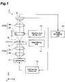
- FIG 1 is a diagram illustrating an embodiment of an image acquisition device according to the present invention.
- an image acquisition device 1 includes a stage 2 on which a sample S is placed, a light source 3 (light emitting means) that irradiates the sample with instantaneous light, a light guiding optical system 5 including an objective lens 25 arranged to face the sample S on the stage 2, and an imaging element 6 that captures an optical image of the sample S guided by the light guiding optical system 5.
- a light source 3 light emitting means
- a light guiding optical system 5 including an objective lens 25 arranged to face the sample S on the stage 2
- an imaging element 6 that captures an optical image of the sample S guided by the light guiding optical system 5.
- the image acquisition device 1 includes a stage driving unit 11 (driving unit) that moves a position of a field of view of the objective lens 25 relative to the sample S, an objective lens driving unit 12 that changes a focal position of the objective lens 25 relative to the sample S, a light source control unit 13 (control unit) that controls the light source 3, and an image processing unit 14.
- the sample S observed by the image acquisition device 1 is, for example, a biological sample, such as tissue cells, and is placed on the stage 2 in a state in which the sample S is sealed on a glass slide.
- the light source 3 is arranged on the bottom side of the stage 2.
- a laser diode (LD), a light emitting diode (LED), a super luminescent diode (SLD), a flash lamp light source such as a xenon flash lamp, or the like is used as the light source 3.
- the light guiding optical system 5 includes an illumination optical system 21 arranged between the light source 3 and the stage 2, and a microscope optical system 22 arranged between the stage 2 and the imaging element 6.
- the illumination optical system 21 includes, for example, a Koehler illumination optical system including a condenser lens 23 and a projection lens 24, and guides light from the light source 3 and irradiates the sample S with uniform light.
- the microscope optical system 22 includes the objective lens 25, and an image forming lens 26 arranged on the downstream side (imaging element 6 side) of the objective lens 25, and guides an optical image of the sample S to the imaging element 6.
- the optical image of the sample S is an image formed by transmitted light in the case of bright field illumination, scattered light in the case of dark field illumination, or emitted light (fluorescence) in the case of emitted light measurement. Further, the optical image of the sample S may also be an image formed by reflected light from the sample S. In these cases, an optical system corresponding to image acquisition of the transmitted light image, the scattered light image, and the emitted light (fluorescence) image of the sample S can be adopted as the light guiding optical system 5.
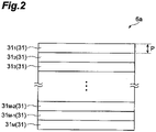
- the imaging element 6 is a two-dimensional imaging element having a plurality of pixel rows. Examples of such an imaging element 6 may include a CCD image sensor or a CMOS image sensor. On a light reception surface 6a of the imaging element 6, for example, M pixel rows 31 (a first pixel row 31 1 , a second pixel row 31 2 , a third pixel row 31 3 , ..., a (M-2)-th pixel row 31 M-2 , a (M-1)-th pixel row 31 M-1 , and an M-th pixel row 31 M ) in which a plurality of pixels are one-dimensionally arranged are arranged in parallel, as illustrated in FIG 2 .
- M pixel rows 31 a first pixel row 31 1 , a second pixel row 31 2 , a third pixel row 31 3 , ..., a (M-2)-th pixel row 31 M-2 , a (M-1)-th pixel row 31 M-1 , and an M-th pixel row 31 M
- a length (pixel width) P in an arrangement direction (reading direction) of each pixel row 31 is, for example, about 1.5 ⁇ m.
- the imaging element 6 sequentially captures an optical image of the sample S guided by the light guiding optical system 5 at a predetermined frame rate ⁇ (for example, less than 30 frames per second (fps)).
- the stage driving unit 11 includes, for example, a motor such as a stepping motor (pulse motor) or an actuator such as a piezoelectric actuator.
- the stage driving unit 11 drives the stage 2 in an XY direction relative to a surface having a predetermined angle (for example, 90°) with respect to a plane perpendicular to an optical axis of the objective lens 25. Accordingly, the sample S fixed to the stage 2 is moved relative to the optical axis of the objective lens, and a position of the field of view of the objective lens 25 relative to the sample S is moved.
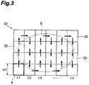
- the field of view F of the objective lens 25 is smaller than the sample S and, as illustrated in FIG 3 , a region in which an image can be acquired by onetime imaging becomes smaller than the sample S. Accordingly, in order to image the entire sample S, it is necessary for the field of view F of the objective lens 25 to be moved relative to the sample S.
- an image acquisition region 32 is set to include the sample S with respect to a sample container (for example, a glass slide) holding the sample S, and positions of a plurality of divided regions 33 are set based on the image acquisition region 32 and the field of view F of the objective lens 25 on the sample S.
- a portion of the sample S corresponding to a divided region 33 is imaged so as to acquire partial image data corresponding to the divided region 33, and then, if the field of view F of the objective lens 25 constitutes a position of the divided region 33 to be imaged next, imaging is performed again to acquire partial image data. Thereafter, in the image acquisition device 1, this operation is repeatedly executed, and the image processing unit 14 combines the acquired partial image data to form the entire image (combined image data) of the sample S.
- the stage driving unit 11 drives the stage 2 so that a position of the field of view F of the objective lens 25 relative to the sample S is moved in a scan direction along an imaging line Ln (n is a natural number) including a plurality of divided regions 33.
- an imaging line Ln (n is a natural number) including a plurality of divided regions 33.
- bidirectional scanning in which a scan direction is reversed between the adjacent imaging lines Ln is adopted, for example, as illustrated in FIG 3 .
- unidirectional scanning in which the scan direction is the same direction between the adjacent imaging lines Ln may be employed.
- the direction along an imaging line Ln corresponds to the arrangement direction of the respective pixel rows 31 on the light reception surface 6a of the imaging element 6.
- the stage driving unit 11 drives the stage 2 at a velocity set based on the frame rate ⁇ of the imaging element 6. That is, the stage driving unit 11 drives the stage 2 at a velocity such that a timing at which the field of view F of the objective lens 25 constitutes the position of each divided region 33 matches a timing at which the imaging element 6 performs imaging.
- the stage driving unit 11 drives the stage 2, for example, at a velocity V shown in Equation (1) below based on the number M of pixel rows 31.
- V A ⁇ M ⁇ ⁇
- the stage driving unit 11 may drive, for example, the stage 2 at a velocity V expressed by Equation (2) below obtained by rewriting Equation (1).
- V H1 ⁇ ⁇
- H1 denotes a length in a direction along an imaging line Ln of the field of view F of the objective lens 25.
- the objective lens driving unit 12 includes, for example, a motor such as a stepping motor (pulse motor) or an actuator such as a piezoelectric actuator, similar to the stage driving unit 11.
- the objective lens driving unit 12 drives the objective lens 25 in a Z direction along the optical axis of the objective lens 25. Accordingly, the focal position of the objective lens 25 relative to the sample S is moved.
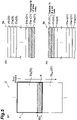
- the light source control unit 13 causes the instantaneous light to be emitted from the light source 3, as illustrated in FIG 4 . That is, first, the imaging element 6 alternately performs exposure and reading, and outputs a trigger signal to the light source control unit 13 when all the pixel rows 31 (a first pixel row 31 1 , a second pixel row 31 2 , a third pixel row 31 3 , ..., an M-th pixel row 31 M ) are exposed.
- the light source control unit 13 causes the instantaneous light to be emitted from the light source 3 based on the trigger signal indicating that all the pixel rows 31 are exposed, which is output from the imaging element 6.
- W A/V
- the stage driving unit 11 driving the stage 2
- the position of the field of view F of the objective lens 25 relative to the sample S is moved, and the imaging element 6 which is a two-dimensional imaging element sequentially captures the optical image of the sample S at a predetermined frame rate ⁇ . Therefore, time for acquiring the partial images over the entire sample S is shortened. Further, in the image acquisition device 1, the stage driving unit 11 drives the stage 2 at a velocity based on the frame rate ⁇ of the imaging element 6.
- the light source control unit 13 causes the instantaneous light to be emitted from the light source 3 during a period of time in which all the pixel rows 31 are exposed, based on the trigger signal indicating that all the pixel rows 31 are exposed, which is output from the imaging element 6. Therefore, the partial images can be reliably acquired in all of the divided regions 33.
- the present invention is not limited to the above embodiment.
- the light source control unit 13 may cause the instantaneous light to be emitted from the light source 3 during the period of time in which all the pixel rows 31 are exposed, by setting a timing at which the instantaneous light is caused to emitted from the light source 3 to be synchronized with a timing at which the imaging element 6 performs imaging based on the frame rate ⁇ of the imaging element 6.
- the partial images can be reliably acquired in all of the divided regions 33.
- continuous light may be emitted from the light source 3 and a shutter may be provided between the light source 3 and the sample S.
- a light emitting means is configured with the light source 3 and the shutter, and the light source control unit 13 controls opening and closing of the shutter. Accordingly, the sample S can be irradiated with the instantaneous light during the period of time in which all the pixel rows 31 are exposed.
- a light guiding optical system driving unit driving unit that drives the light guiding optical system 5 including the objective lens 25 may be provided, and the position of the field of view of the objective lens 25 relative to the sample S may be moved by the light guiding optical system driving unit.
- the focal position of the objective lens 25 relative to the sample S is moved in the optical axis direction of the objective lens 25 by the objective lens driving unit 12 moving the objective lens 25 in the optical axis direction thereof in the above embodiment
- the focal position of the objective lens 25 relative to the sample S may be moved in the optical axis direction of the objective lens 25 by the stage driving unit 11 moving the stage 2 in the optical axis direction of the objective lens 25.
- stage driving unit 11 drives the stage 2 so that two divided regions 33 to be continuously captured come in contact with each other in the above embodiment, the stage driving unit 11 may drive the stage 2 so that the two divided regions 33 to be continuously captured partially overlap each other.
- the stage driving unit 11 may drive the stage 2 so that an overlapping region R in which a portion of the divided region 33 S and a portion of the divided regions 33 S+1 overlap each other is formed.
- the stage driving unit 11 can drive the stage 2 at a velocity V' shown in Equation (4) below, for example, based on the number N of pixel rows on the light reception surface 6a of the imaging element 6 corresponding to the overlapping region R.
- V ′ A ⁇ M ⁇ N ⁇ ⁇
- the stage driving unit 11 may drive the stage 2, for example, at a velocity V' shown in Equation (5) below obtained by rewriting Equation (4).
- V ′ H1 ⁇ H2 ⁇ ⁇
- H2 denotes a length of the overlapping region R in a direction along an imaging line Lt
- the driving velocity of the stage 2 is set in consideration of the relationship between the overlapping region R and the the number N of pixel rows on the light reception surface 6a of the imaging element 6 corresponding to the overlapping region R, the overlapping region R is reliably formed. Accordingly, when the obtained partial images are combined, the partial images can be smoothly combined and an entire continuous image can be acquired.
- 1 image acquisition device
- 2 stage
- 3 light source (light emitting means)
- 5 light guiding optical system
- 6 imaging element
- 11 stage driving unit (driving unit)
- 12 objective lens driving unit
- 13 light source control unit (control unit)
- 14 image processing unit
- 22 microscope optical system
- 25 objective lens
- 31 pixel row
- 32 image acquisition region
- 33 divided region
- F field of view of objective lens
- R overlapping region
- S sample.
Landscapes
- Physics & Mathematics (AREA)
- Engineering & Computer Science (AREA)
- Multimedia (AREA)
- General Physics & Mathematics (AREA)
- Chemical & Material Sciences (AREA)
- Analytical Chemistry (AREA)
- Optics & Photonics (AREA)
- Computer Vision & Pattern Recognition (AREA)
- Health & Medical Sciences (AREA)
- Life Sciences & Earth Sciences (AREA)
- Biomedical Technology (AREA)
- General Health & Medical Sciences (AREA)
- Molecular Biology (AREA)
- Theoretical Computer Science (AREA)
- Microscoopes, Condenser (AREA)
- Studio Devices (AREA)
- Image Input (AREA)
Applications Claiming Priority (2)
| Application Number | Priority Date | Filing Date | Title |
|---|---|---|---|
| JP2013228560A JP6154291B2 (ja) | 2013-11-01 | 2013-11-01 | 画像取得装置及び画像取得装置の画像取得方法 |
| PCT/JP2014/051804 WO2015064116A1 (ja) | 2013-11-01 | 2014-01-28 | 画像取得装置及び画像取得装置の画像取得方法 |
Publications (3)
| Publication Number | Publication Date |
|---|---|
| EP3064981A1 EP3064981A1 (en) | 2016-09-07 |
| EP3064981A4 EP3064981A4 (en) | 2017-04-05 |
| EP3064981B1 true EP3064981B1 (en) | 2022-04-20 |
Family
ID=53003740
Family Applications (1)
| Application Number | Title | Priority Date | Filing Date |
|---|---|---|---|
| EP14856848.8A Active EP3064981B1 (en) | 2013-11-01 | 2014-01-28 | Image acquisition device and image acquisition method for image acquisition device |
Country Status (7)
Families Citing this family (10)
| Publication number | Priority date | Publication date | Assignee | Title |
|---|---|---|---|---|
| JP6698451B2 (ja) * | 2016-07-11 | 2020-05-27 | オリンパス株式会社 | 観察装置 |
| CN107782738A (zh) * | 2016-08-31 | 2018-03-09 | 上海微电子装备(集团)股份有限公司 | 一种自动光学检测装置及其检测方法 |
| JP6865010B2 (ja) * | 2016-10-19 | 2021-04-28 | オリンパス株式会社 | 顕微鏡システムおよび標本観察方法 |
| JP6842387B2 (ja) | 2017-08-31 | 2021-03-17 | 浜松ホトニクス株式会社 | 画像取得装置及び画像取得方法 |
| JP7023659B2 (ja) * | 2017-09-29 | 2022-02-22 | キヤノン株式会社 | 撮像装置、撮像システム、移動体 |
| JP6920978B2 (ja) * | 2017-12-18 | 2021-08-18 | 浜松ホトニクス株式会社 | 画像取得装置及び画像取得方法 |
| FR3081552B1 (fr) * | 2018-05-23 | 2020-05-29 | Commissariat A L'energie Atomique Et Aux Energies Alternatives | Dispositif et procede d'observation d'un echantillon fluorescent par imagerie defocalisee |
| CN109752916A (zh) * | 2018-12-26 | 2019-05-14 | 江苏大学 | 一种平面激光拍摄装置及其方法 |
| TW202336423A (zh) | 2021-10-01 | 2023-09-16 | 美商伊路米納有限公司 | 用於傳輸光之設備及方法 |
| KR102596730B1 (ko) * | 2022-02-16 | 2023-11-02 | 주식회사 팍스웰 | 렌즈없는 광학 시스템 |
Family Cites Families (15)
| Publication number | Priority date | Publication date | Assignee | Title |
|---|---|---|---|---|
| JPS63191063A (ja) | 1987-02-03 | 1988-08-08 | Sumitomo Electric Ind Ltd | 顕微鏡画像の処理方式 |
| CA2227177A1 (en) | 1995-07-19 | 1997-02-06 | Morphometrix Technologies Inc. | Automated scanning of microscope slides |
| JPH09281405A (ja) * | 1996-04-17 | 1997-10-31 | Olympus Optical Co Ltd | 顕微鏡システム |
| JPH11326233A (ja) * | 1998-05-12 | 1999-11-26 | Mitsui Mining & Smelting Co Ltd | 材料表面検査装置 |
| GB2383487B (en) * | 2001-12-18 | 2006-09-27 | Fairfield Imaging Ltd | Method and apparatus for acquiring digital microscope images |
| JP2003222801A (ja) * | 2002-01-29 | 2003-08-08 | Olympus Optical Co Ltd | 顕微鏡画像撮影装置 |
| ATE414274T1 (de) * | 2003-01-15 | 2008-11-15 | Negevtech Ltd | Verfahren und gerät zur schnellen on-line und elektro-optischen defekterkennung an wafern |
| JP4102842B1 (ja) * | 2006-12-04 | 2008-06-18 | 東京エレクトロン株式会社 | 欠陥検出装置、欠陥検出方法、情報処理装置、情報処理方法及びそのプログラム |
| JP5289756B2 (ja) * | 2007-11-26 | 2013-09-11 | オリンパス株式会社 | 顕微鏡観察システム |
| JP2010002534A (ja) * | 2008-06-19 | 2010-01-07 | Nikon Corp | 顕微鏡装置 |
| JP5290053B2 (ja) * | 2009-05-21 | 2013-09-18 | オリンパス株式会社 | 顕微鏡システム |
| JP5365407B2 (ja) * | 2009-08-17 | 2013-12-11 | ソニー株式会社 | 画像取得装置及び画像取得方法 |
| CN102854615B (zh) * | 2012-04-27 | 2015-07-22 | 麦克奥迪实业集团有限公司 | 一种对显微切片的全自动扫描系统及方法 |
| JP2014026233A (ja) * | 2012-07-30 | 2014-02-06 | Olympus Corp | 撮像システム |
| WO2014127468A1 (en) * | 2013-02-25 | 2014-08-28 | Huron Technologies International Inc. | Microscopy slide scanner with variable magnification |
-
2013
- 2013-11-01 JP JP2013228560A patent/JP6154291B2/ja active Active
-
2014
- 2014-01-28 CN CN201480058554.5A patent/CN105683805B/zh active Active
- 2014-01-28 WO PCT/JP2014/051804 patent/WO2015064116A1/ja active Application Filing
- 2014-01-28 EP EP14856848.8A patent/EP3064981B1/en active Active
- 2014-01-28 DK DK14856848.8T patent/DK3064981T3/da active
- 2014-01-28 HU HUE14856848A patent/HUE059480T2/hu unknown
- 2014-01-28 US US15/031,083 patent/US9911028B2/en active Active
Also Published As
| Publication number | Publication date |
|---|---|
| DK3064981T3 (da) | 2022-06-13 |
| EP3064981A4 (en) | 2017-04-05 |
| EP3064981A1 (en) | 2016-09-07 |
| WO2015064116A1 (ja) | 2015-05-07 |
| US20160267317A1 (en) | 2016-09-15 |
| JP6154291B2 (ja) | 2017-06-28 |
| US9911028B2 (en) | 2018-03-06 |
| CN105683805B (zh) | 2018-09-28 |
| HUE059480T2 (hu) | 2022-11-28 |
| CN105683805A (zh) | 2016-06-15 |
| JP2015087719A (ja) | 2015-05-07 |
Similar Documents
| Publication | Publication Date | Title |
|---|---|---|
| EP3064981B1 (en) | Image acquisition device and image acquisition method for image acquisition device | |
| US10602087B2 (en) | Image acquisition device, and imaging device | |
| CN105283791B (zh) | 图像取得装置及图像取得装置的聚焦方法 | |
| EP2495592A1 (en) | Three-dimensional directional drift control device and microscope device | |
| KR20090077036A (ko) | 동적 주사 자동 현미경 및 동적 주사 방법 | |
| CN111033352B (zh) | 图像取得装置和图像取得方法 | |
| US20240205546A1 (en) | Impulse rescan system | |
| EP3064982B1 (en) | Image acquisition device and image acquisition method for image acquisition device | |
| JP2008051772A (ja) | 蛍光画像取得装置、及び蛍光画像取得方法 | |
| JP6496772B2 (ja) | 画像取得装置及び画像取得方法 | |
| US20130162801A1 (en) | Microscope | |
| US12228716B2 (en) | Microscope and method for imaging an object using a microscope | |
| JP2016126129A (ja) | 光学観察装置 | |
| JP2012181340A (ja) | 顕微鏡装置 |
Legal Events
| Date | Code | Title | Description |
|---|---|---|---|
| PUAI | Public reference made under article 153(3) epc to a published international application that has entered the european phase |
Free format text: ORIGINAL CODE: 0009012 |
|
| 17P | Request for examination filed |
Effective date: 20160510 |
|
| AK | Designated contracting states |
Kind code of ref document: A1 Designated state(s): AL AT BE BG CH CY CZ DE DK EE ES FI FR GB GR HR HU IE IS IT LI LT LU LV MC MK MT NL NO PL PT RO RS SE SI SK SM TR |
|
| AX | Request for extension of the european patent |
Extension state: BA ME |
|
| DAX | Request for extension of the european patent (deleted) | ||
| A4 | Supplementary search report drawn up and despatched |
Effective date: 20170302 |
|
| RIC1 | Information provided on ipc code assigned before grant |
Ipc: G02B 21/36 20060101AFI20170224BHEP Ipc: H04N 5/225 20060101ALI20170224BHEP |
|
| STAA | Information on the status of an ep patent application or granted ep patent |
Free format text: STATUS: EXAMINATION IS IN PROGRESS |
|
| RIC1 | Information provided on ipc code assigned before grant |
Ipc: H04N 5/225 20060101ALI20191203BHEP Ipc: G02B 21/36 20060101AFI20191203BHEP Ipc: G02B 21/08 20060101ALI20191203BHEP |
|
| 17Q | First examination report despatched |
Effective date: 20191211 |
|
| GRAP | Despatch of communication of intention to grant a patent |
Free format text: ORIGINAL CODE: EPIDOSNIGR1 |
|
| STAA | Information on the status of an ep patent application or granted ep patent |
Free format text: STATUS: GRANT OF PATENT IS INTENDED |
|
| INTG | Intention to grant announced |
Effective date: 20220121 |
|
| GRAS | Grant fee paid |
Free format text: ORIGINAL CODE: EPIDOSNIGR3 |
|
| GRAA | (expected) grant |
Free format text: ORIGINAL CODE: 0009210 |
|
| STAA | Information on the status of an ep patent application or granted ep patent |
Free format text: STATUS: THE PATENT HAS BEEN GRANTED |
|
| AK | Designated contracting states |
Kind code of ref document: B1 Designated state(s): AL AT BE BG CH CY CZ DE DK EE ES FI FR GB GR HR HU IE IS IT LI LT LU LV MC MK MT NL NO PL PT RO RS SE SI SK SM TR |
|
| REG | Reference to a national code |
Ref country code: GB Ref legal event code: FG4D |
|
| REG | Reference to a national code |
Ref country code: CH Ref legal event code: EP |
|
| REG | Reference to a national code |
Ref country code: DE Ref legal event code: R096 Ref document number: 602014083364 Country of ref document: DE |
|
| REG | Reference to a national code |
Ref country code: IE Ref legal event code: FG4D |
|
| REG | Reference to a national code |
Ref country code: AT Ref legal event code: REF Ref document number: 1485615 Country of ref document: AT Kind code of ref document: T Effective date: 20220515 |
|
| REG | Reference to a national code |
Ref country code: DK Ref legal event code: T3 Effective date: 20220609 |
|
| REG | Reference to a national code |
Ref country code: SE Ref legal event code: TRGR |
|
| REG | Reference to a national code |
Ref country code: LT Ref legal event code: MG9D |
|
| REG | Reference to a national code |
Ref country code: NL Ref legal event code: MP Effective date: 20220420 |
|
| REG | Reference to a national code |
Ref country code: AT Ref legal event code: MK05 Ref document number: 1485615 Country of ref document: AT Kind code of ref document: T Effective date: 20220420 |
|
| PG25 | Lapsed in a contracting state [announced via postgrant information from national office to epo] |
Ref country code: NL Free format text: LAPSE BECAUSE OF FAILURE TO SUBMIT A TRANSLATION OF THE DESCRIPTION OR TO PAY THE FEE WITHIN THE PRESCRIBED TIME-LIMIT Effective date: 20220420 |
|
| PG25 | Lapsed in a contracting state [announced via postgrant information from national office to epo] |
Ref country code: PT Free format text: LAPSE BECAUSE OF FAILURE TO SUBMIT A TRANSLATION OF THE DESCRIPTION OR TO PAY THE FEE WITHIN THE PRESCRIBED TIME-LIMIT Effective date: 20220822 Ref country code: NO Free format text: LAPSE BECAUSE OF FAILURE TO SUBMIT A TRANSLATION OF THE DESCRIPTION OR TO PAY THE FEE WITHIN THE PRESCRIBED TIME-LIMIT Effective date: 20220720 Ref country code: LT Free format text: LAPSE BECAUSE OF FAILURE TO SUBMIT A TRANSLATION OF THE DESCRIPTION OR TO PAY THE FEE WITHIN THE PRESCRIBED TIME-LIMIT Effective date: 20220420 Ref country code: HR Free format text: LAPSE BECAUSE OF FAILURE TO SUBMIT A TRANSLATION OF THE DESCRIPTION OR TO PAY THE FEE WITHIN THE PRESCRIBED TIME-LIMIT Effective date: 20220420 Ref country code: GR Free format text: LAPSE BECAUSE OF FAILURE TO SUBMIT A TRANSLATION OF THE DESCRIPTION OR TO PAY THE FEE WITHIN THE PRESCRIBED TIME-LIMIT Effective date: 20220721 Ref country code: FI Free format text: LAPSE BECAUSE OF FAILURE TO SUBMIT A TRANSLATION OF THE DESCRIPTION OR TO PAY THE FEE WITHIN THE PRESCRIBED TIME-LIMIT Effective date: 20220420 Ref country code: ES Free format text: LAPSE BECAUSE OF FAILURE TO SUBMIT A TRANSLATION OF THE DESCRIPTION OR TO PAY THE FEE WITHIN THE PRESCRIBED TIME-LIMIT Effective date: 20220420 Ref country code: BG Free format text: LAPSE BECAUSE OF FAILURE TO SUBMIT A TRANSLATION OF THE DESCRIPTION OR TO PAY THE FEE WITHIN THE PRESCRIBED TIME-LIMIT Effective date: 20220720 Ref country code: AT Free format text: LAPSE BECAUSE OF FAILURE TO SUBMIT A TRANSLATION OF THE DESCRIPTION OR TO PAY THE FEE WITHIN THE PRESCRIBED TIME-LIMIT Effective date: 20220420 |
|
| REG | Reference to a national code |
Ref country code: HU Ref legal event code: AG4A Ref document number: E059480 Country of ref document: HU |
|
| PG25 | Lapsed in a contracting state [announced via postgrant information from national office to epo] |
Ref country code: RS Free format text: LAPSE BECAUSE OF FAILURE TO SUBMIT A TRANSLATION OF THE DESCRIPTION OR TO PAY THE FEE WITHIN THE PRESCRIBED TIME-LIMIT Effective date: 20220420 Ref country code: PL Free format text: LAPSE BECAUSE OF FAILURE TO SUBMIT A TRANSLATION OF THE DESCRIPTION OR TO PAY THE FEE WITHIN THE PRESCRIBED TIME-LIMIT Effective date: 20220420 Ref country code: LV Free format text: LAPSE BECAUSE OF FAILURE TO SUBMIT A TRANSLATION OF THE DESCRIPTION OR TO PAY THE FEE WITHIN THE PRESCRIBED TIME-LIMIT Effective date: 20220420 Ref country code: IS Free format text: LAPSE BECAUSE OF FAILURE TO SUBMIT A TRANSLATION OF THE DESCRIPTION OR TO PAY THE FEE WITHIN THE PRESCRIBED TIME-LIMIT Effective date: 20220820 |
|
| REG | Reference to a national code |
Ref country code: DE Ref legal event code: R097 Ref document number: 602014083364 Country of ref document: DE |
|
| PG25 | Lapsed in a contracting state [announced via postgrant information from national office to epo] |
Ref country code: SM Free format text: LAPSE BECAUSE OF FAILURE TO SUBMIT A TRANSLATION OF THE DESCRIPTION OR TO PAY THE FEE WITHIN THE PRESCRIBED TIME-LIMIT Effective date: 20220420 Ref country code: SK Free format text: LAPSE BECAUSE OF FAILURE TO SUBMIT A TRANSLATION OF THE DESCRIPTION OR TO PAY THE FEE WITHIN THE PRESCRIBED TIME-LIMIT Effective date: 20220420 Ref country code: RO Free format text: LAPSE BECAUSE OF FAILURE TO SUBMIT A TRANSLATION OF THE DESCRIPTION OR TO PAY THE FEE WITHIN THE PRESCRIBED TIME-LIMIT Effective date: 20220420 Ref country code: EE Free format text: LAPSE BECAUSE OF FAILURE TO SUBMIT A TRANSLATION OF THE DESCRIPTION OR TO PAY THE FEE WITHIN THE PRESCRIBED TIME-LIMIT Effective date: 20220420 Ref country code: CZ Free format text: LAPSE BECAUSE OF FAILURE TO SUBMIT A TRANSLATION OF THE DESCRIPTION OR TO PAY THE FEE WITHIN THE PRESCRIBED TIME-LIMIT Effective date: 20220420 |
|
| PLBE | No opposition filed within time limit |
Free format text: ORIGINAL CODE: 0009261 |
|
| STAA | Information on the status of an ep patent application or granted ep patent |
Free format text: STATUS: NO OPPOSITION FILED WITHIN TIME LIMIT |
|
| 26N | No opposition filed |
Effective date: 20230123 |
|
| PG25 | Lapsed in a contracting state [announced via postgrant information from national office to epo] |
Ref country code: AL Free format text: LAPSE BECAUSE OF FAILURE TO SUBMIT A TRANSLATION OF THE DESCRIPTION OR TO PAY THE FEE WITHIN THE PRESCRIBED TIME-LIMIT Effective date: 20220420 |
|
| PG25 | Lapsed in a contracting state [announced via postgrant information from national office to epo] |
Ref country code: SI Free format text: LAPSE BECAUSE OF FAILURE TO SUBMIT A TRANSLATION OF THE DESCRIPTION OR TO PAY THE FEE WITHIN THE PRESCRIBED TIME-LIMIT Effective date: 20220420 |
|
| P01 | Opt-out of the competence of the unified patent court (upc) registered |
Effective date: 20230509 |
|
| REG | Reference to a national code |
Ref country code: CH Ref legal event code: PL |
|
| PG25 | Lapsed in a contracting state [announced via postgrant information from national office to epo] |
Ref country code: LU Free format text: LAPSE BECAUSE OF NON-PAYMENT OF DUE FEES Effective date: 20230128 |
|
| REG | Reference to a national code |
Ref country code: BE Ref legal event code: MM Effective date: 20230131 |
|
| PG25 | Lapsed in a contracting state [announced via postgrant information from national office to epo] |
Ref country code: LI Free format text: LAPSE BECAUSE OF NON-PAYMENT OF DUE FEES Effective date: 20230131 Ref country code: CH Free format text: LAPSE BECAUSE OF NON-PAYMENT OF DUE FEES Effective date: 20230131 |
|
| PG25 | Lapsed in a contracting state [announced via postgrant information from national office to epo] |
Ref country code: BE Free format text: LAPSE BECAUSE OF NON-PAYMENT OF DUE FEES Effective date: 20230131 |
|
| PG25 | Lapsed in a contracting state [announced via postgrant information from national office to epo] |
Ref country code: IT Free format text: LAPSE BECAUSE OF FAILURE TO SUBMIT A TRANSLATION OF THE DESCRIPTION OR TO PAY THE FEE WITHIN THE PRESCRIBED TIME-LIMIT Effective date: 20220420 Ref country code: IE Free format text: LAPSE BECAUSE OF NON-PAYMENT OF DUE FEES Effective date: 20230128 |
|
| PG25 | Lapsed in a contracting state [announced via postgrant information from national office to epo] |
Ref country code: MC Free format text: LAPSE BECAUSE OF FAILURE TO SUBMIT A TRANSLATION OF THE DESCRIPTION OR TO PAY THE FEE WITHIN THE PRESCRIBED TIME-LIMIT Effective date: 20220420 |
|
| PG25 | Lapsed in a contracting state [announced via postgrant information from national office to epo] |
Ref country code: MC Free format text: LAPSE BECAUSE OF FAILURE TO SUBMIT A TRANSLATION OF THE DESCRIPTION OR TO PAY THE FEE WITHIN THE PRESCRIBED TIME-LIMIT Effective date: 20220420 |
|
| PG25 | Lapsed in a contracting state [announced via postgrant information from national office to epo] |
Ref country code: BG Free format text: LAPSE BECAUSE OF FAILURE TO SUBMIT A TRANSLATION OF THE DESCRIPTION OR TO PAY THE FEE WITHIN THE PRESCRIBED TIME-LIMIT Effective date: 20220420 |
|
| PG25 | Lapsed in a contracting state [announced via postgrant information from national office to epo] |
Ref country code: BG Free format text: LAPSE BECAUSE OF FAILURE TO SUBMIT A TRANSLATION OF THE DESCRIPTION OR TO PAY THE FEE WITHIN THE PRESCRIBED TIME-LIMIT Effective date: 20220420 |
|
| PGFP | Annual fee paid to national office [announced via postgrant information from national office to epo] |
Ref country code: GB Payment date: 20241205 Year of fee payment: 12 |
|
| PGFP | Annual fee paid to national office [announced via postgrant information from national office to epo] |
Ref country code: FR Payment date: 20241209 Year of fee payment: 12 |
|
| PGFP | Annual fee paid to national office [announced via postgrant information from national office to epo] |
Ref country code: SE Payment date: 20241212 Year of fee payment: 12 |
|
| PGFP | Annual fee paid to national office [announced via postgrant information from national office to epo] |
Ref country code: HU Payment date: 20241218 Year of fee payment: 12 |
|
| PGFP | Annual fee paid to national office [announced via postgrant information from national office to epo] |
Ref country code: DE Payment date: 20241203 Year of fee payment: 12 |
|
| PGFP | Annual fee paid to national office [announced via postgrant information from national office to epo] |
Ref country code: DK Payment date: 20250113 Year of fee payment: 12 |
|
| PG25 | Lapsed in a contracting state [announced via postgrant information from national office to epo] |
Ref country code: CY Free format text: LAPSE BECAUSE OF FAILURE TO SUBMIT A TRANSLATION OF THE DESCRIPTION OR TO PAY THE FEE WITHIN THE PRESCRIBED TIME-LIMIT; INVALID AB INITIO Effective date: 20140128 |