WO2015064015A1 - 積層塗膜及び塗装物 - Google Patents
積層塗膜及び塗装物 Download PDFInfo
- Publication number
- WO2015064015A1 WO2015064015A1 PCT/JP2014/005061 JP2014005061W WO2015064015A1 WO 2015064015 A1 WO2015064015 A1 WO 2015064015A1 JP 2014005061 W JP2014005061 W JP 2014005061W WO 2015064015 A1 WO2015064015 A1 WO 2015064015A1
- Authority
- WO
- WIPO (PCT)
- Prior art keywords
- coating film
- refractive index
- clear
- layer coating
- colorant
- Prior art date
- Legal status (The legal status is an assumption and is not a legal conclusion. Google has not performed a legal analysis and makes no representation as to the accuracy of the status listed.)
- Ceased
Links
Images



Classifications
-
- B—PERFORMING OPERATIONS; TRANSPORTING
- B05—SPRAYING OR ATOMISING IN GENERAL; APPLYING FLUENT MATERIALS TO SURFACES, IN GENERAL
- B05D—PROCESSES FOR APPLYING FLUENT MATERIALS TO SURFACES, IN GENERAL
- B05D5/00—Processes for applying liquids or other fluent materials to surfaces to obtain special surface effects, finishes or structures
- B05D5/06—Processes for applying liquids or other fluent materials to surfaces to obtain special surface effects, finishes or structures to obtain multicolour or other optical effects
- B05D5/065—Processes for applying liquids or other fluent materials to surfaces to obtain special surface effects, finishes or structures to obtain multicolour or other optical effects having colour interferences or colour shifts or opalescent looking, flip-flop, two tones
-
- B—PERFORMING OPERATIONS; TRANSPORTING
- B05—SPRAYING OR ATOMISING IN GENERAL; APPLYING FLUENT MATERIALS TO SURFACES, IN GENERAL
- B05D—PROCESSES FOR APPLYING FLUENT MATERIALS TO SURFACES, IN GENERAL
- B05D5/00—Processes for applying liquids or other fluent materials to surfaces to obtain special surface effects, finishes or structures
- B05D5/06—Processes for applying liquids or other fluent materials to surfaces to obtain special surface effects, finishes or structures to obtain multicolour or other optical effects
-
- B—PERFORMING OPERATIONS; TRANSPORTING
- B05—SPRAYING OR ATOMISING IN GENERAL; APPLYING FLUENT MATERIALS TO SURFACES, IN GENERAL
- B05D—PROCESSES FOR APPLYING FLUENT MATERIALS TO SURFACES, IN GENERAL
- B05D7/00—Processes, other than flocking, specially adapted for applying liquids or other fluent materials to particular surfaces or for applying particular liquids or other fluent materials
- B05D7/50—Multilayers
-
- B—PERFORMING OPERATIONS; TRANSPORTING
- B05—SPRAYING OR ATOMISING IN GENERAL; APPLYING FLUENT MATERIALS TO SURFACES, IN GENERAL
- B05D—PROCESSES FOR APPLYING FLUENT MATERIALS TO SURFACES, IN GENERAL
- B05D7/00—Processes, other than flocking, specially adapted for applying liquids or other fluent materials to particular surfaces or for applying particular liquids or other fluent materials
- B05D7/50—Multilayers
- B05D7/52—Two layers
- B05D7/54—No clear coat specified
-
- B—PERFORMING OPERATIONS; TRANSPORTING
- B32—LAYERED PRODUCTS
- B32B—LAYERED PRODUCTS, i.e. PRODUCTS BUILT-UP OF STRATA OF FLAT OR NON-FLAT, e.g. CELLULAR OR HONEYCOMB, FORM
- B32B15/00—Layered products comprising a layer of metal
- B32B15/04—Layered products comprising a layer of metal comprising metal as the main or only constituent of a layer, which is next to another layer of the same or of a different material
- B32B15/08—Layered products comprising a layer of metal comprising metal as the main or only constituent of a layer, which is next to another layer of the same or of a different material of synthetic resin
-
- B—PERFORMING OPERATIONS; TRANSPORTING
- B32—LAYERED PRODUCTS
- B32B—LAYERED PRODUCTS, i.e. PRODUCTS BUILT-UP OF STRATA OF FLAT OR NON-FLAT, e.g. CELLULAR OR HONEYCOMB, FORM
- B32B15/00—Layered products comprising a layer of metal
- B32B15/18—Layered products comprising a layer of metal comprising iron or steel
-
- B—PERFORMING OPERATIONS; TRANSPORTING
- B32—LAYERED PRODUCTS
- B32B—LAYERED PRODUCTS, i.e. PRODUCTS BUILT-UP OF STRATA OF FLAT OR NON-FLAT, e.g. CELLULAR OR HONEYCOMB, FORM
- B32B27/00—Layered products comprising a layer of synthetic resin
- B32B27/06—Layered products comprising a layer of synthetic resin as the main or only constituent of a layer, which is next to another layer of the same or of a different material
- B32B27/08—Layered products comprising a layer of synthetic resin as the main or only constituent of a layer, which is next to another layer of the same or of a different material of synthetic resin
-
- B—PERFORMING OPERATIONS; TRANSPORTING
- B32—LAYERED PRODUCTS
- B32B—LAYERED PRODUCTS, i.e. PRODUCTS BUILT-UP OF STRATA OF FLAT OR NON-FLAT, e.g. CELLULAR OR HONEYCOMB, FORM
- B32B27/00—Layered products comprising a layer of synthetic resin
- B32B27/18—Layered products comprising a layer of synthetic resin characterised by the use of special additives
- B32B27/20—Layered products comprising a layer of synthetic resin characterised by the use of special additives using fillers, pigments, thixotroping agents
-
- G—PHYSICS
- G02—OPTICS
- G02B—OPTICAL ELEMENTS, SYSTEMS OR APPARATUS
- G02B5/00—Optical elements other than lenses
- G02B5/20—Filters
- G02B5/206—Filters comprising particles embedded in a solid matrix
-
- G—PHYSICS
- G02—OPTICS
- G02B—OPTICAL ELEMENTS, SYSTEMS OR APPARATUS
- G02B5/00—Optical elements other than lenses
- G02B5/20—Filters
- G02B5/28—Interference filters
- G02B5/285—Interference filters comprising deposited thin solid films
- G02B5/286—Interference filters comprising deposited thin solid films having four or fewer layers, e.g. for achieving a colour effect
-
- B—PERFORMING OPERATIONS; TRANSPORTING
- B32—LAYERED PRODUCTS
- B32B—LAYERED PRODUCTS, i.e. PRODUCTS BUILT-UP OF STRATA OF FLAT OR NON-FLAT, e.g. CELLULAR OR HONEYCOMB, FORM
- B32B2255/00—Coating on the layer surface
- B32B2255/06—Coating on the layer surface on metal layer
-
- B—PERFORMING OPERATIONS; TRANSPORTING
- B32—LAYERED PRODUCTS
- B32B—LAYERED PRODUCTS, i.e. PRODUCTS BUILT-UP OF STRATA OF FLAT OR NON-FLAT, e.g. CELLULAR OR HONEYCOMB, FORM
- B32B2255/00—Coating on the layer surface
- B32B2255/26—Polymeric coating
-
- B—PERFORMING OPERATIONS; TRANSPORTING
- B32—LAYERED PRODUCTS
- B32B—LAYERED PRODUCTS, i.e. PRODUCTS BUILT-UP OF STRATA OF FLAT OR NON-FLAT, e.g. CELLULAR OR HONEYCOMB, FORM
- B32B2307/00—Properties of the layers or laminate
- B32B2307/40—Properties of the layers or laminate having particular optical properties
- B32B2307/402—Coloured
-
- B—PERFORMING OPERATIONS; TRANSPORTING
- B32—LAYERED PRODUCTS
- B32B—LAYERED PRODUCTS, i.e. PRODUCTS BUILT-UP OF STRATA OF FLAT OR NON-FLAT, e.g. CELLULAR OR HONEYCOMB, FORM
- B32B2307/00—Properties of the layers or laminate
- B32B2307/40—Properties of the layers or laminate having particular optical properties
- B32B2307/418—Refractive
-
- B—PERFORMING OPERATIONS; TRANSPORTING
- B32—LAYERED PRODUCTS
- B32B—LAYERED PRODUCTS, i.e. PRODUCTS BUILT-UP OF STRATA OF FLAT OR NON-FLAT, e.g. CELLULAR OR HONEYCOMB, FORM
- B32B2605/00—Vehicles
- B32B2605/08—Cars
-
- Y—GENERAL TAGGING OF NEW TECHNOLOGICAL DEVELOPMENTS; GENERAL TAGGING OF CROSS-SECTIONAL TECHNOLOGIES SPANNING OVER SEVERAL SECTIONS OF THE IPC; TECHNICAL SUBJECTS COVERED BY FORMER USPC CROSS-REFERENCE ART COLLECTIONS [XRACs] AND DIGESTS
- Y10—TECHNICAL SUBJECTS COVERED BY FORMER USPC
- Y10T—TECHNICAL SUBJECTS COVERED BY FORMER US CLASSIFICATION
- Y10T428/00—Stock material or miscellaneous articles
- Y10T428/24—Structurally defined web or sheet [e.g., overall dimension, etc.]
- Y10T428/24942—Structurally defined web or sheet [e.g., overall dimension, etc.] including components having same physical characteristic in differing degree
-
- Y—GENERAL TAGGING OF NEW TECHNOLOGICAL DEVELOPMENTS; GENERAL TAGGING OF CROSS-SECTIONAL TECHNOLOGIES SPANNING OVER SEVERAL SECTIONS OF THE IPC; TECHNICAL SUBJECTS COVERED BY FORMER USPC CROSS-REFERENCE ART COLLECTIONS [XRACs] AND DIGESTS
- Y10—TECHNICAL SUBJECTS COVERED BY FORMER USPC
- Y10T—TECHNICAL SUBJECTS COVERED BY FORMER US CLASSIFICATION
- Y10T428/00—Stock material or miscellaneous articles
- Y10T428/25—Web or sheet containing structurally defined element or component and including a second component containing structurally defined particles
-
- Y—GENERAL TAGGING OF NEW TECHNOLOGICAL DEVELOPMENTS; GENERAL TAGGING OF CROSS-SECTIONAL TECHNOLOGIES SPANNING OVER SEVERAL SECTIONS OF THE IPC; TECHNICAL SUBJECTS COVERED BY FORMER USPC CROSS-REFERENCE ART COLLECTIONS [XRACs] AND DIGESTS
- Y10—TECHNICAL SUBJECTS COVERED BY FORMER USPC
- Y10T—TECHNICAL SUBJECTS COVERED BY FORMER US CLASSIFICATION
- Y10T428/00—Stock material or miscellaneous articles
- Y10T428/25—Web or sheet containing structurally defined element or component and including a second component containing structurally defined particles
- Y10T428/259—Silicic material
Definitions
- the present invention relates to a laminated coating film and a painted product.
- an undercoating film is formed by an electrodeposition coating for rust prevention, an intermediate coating film having a base concealing property is formed thereon, and an overcoating film (base coating film is formed thereon.
- a coating film structure in which a clear coating film) is stacked is used.
- a base coating film having a base concealing property is formed on a cationic electrodeposition coating film, and a clear coating film is formed thereon.
- Patent Document 1 discloses that the clear coating film has a refractive index of 1.522, and the difference in refractive index between the base coating film and the clear coating film is 0.015 or more. Is changed depending on the viewing angle. Further, Patent Document 1 describes that an acrylic resin using 50% by mass or more of t-butyl methacrylate exhibits a low refractive index, and an acrylic resin using 40% by mass or more of styrene exhibits a high refractive index. Has been.
- Patent Document 2 describes that when ZnO 2 nanoparticles are dispersed in a resin, the refractive index of the resin can be increased, and that such a resin is used as a coating composition.
- Patent Document 3 describes that antireflection surface characteristics are obtained by applying a silane coating composition containing silica nanoparticles to a clear-coated automobile body panel.
- Paint has a strong aspect of imparting design properties to the object to be coated.
- individual tastes have diversified, and it is sometimes preferred that the color appears vividly, or a slightly dark and calm color. Or it may be preferred that brightness changes depending on the viewing angle.
- the first aspect of the present invention relates to a laminated coating film comprising a lower coating film containing a colorant and an upper coating film laminated thereon, and vividly by controlling the refractive index of both coating films. And to obtain a deep paint color.
- the second aspect of the present invention relates to a laminated coating film comprising a lower coating film containing a colorant and an upper coating film laminated thereon, and by controlling the refractive index of both coating films, the FF property ( It is to obtain a calm paint color having a high flip-flop property.
- the refractive index of the upper layer coating film is lowered and the refractive index of the lower layer coating film is set in relation to the refractive index of the upper layer coating film.
- the multilayer coating film according to this aspect includes a lower layer coating film containing a colorant and an upper layer coating film laminated on the lower layer coating film, and excludes the coloring material of the upper layer coating film.
- the refractive index n1 of the forming element is 1.2 or more and 1.5 or less, and the ratio n1 between the refractive index n1 of the upper coating film and the refractive index n2 of the coating film forming element excluding the colorant in at least the surface layer of the lower coating film / N2 is 0.67 or more and 1 or less.
- colorant refers to a component that imparts color to a coating film, such as a pigment, a dye, or a bright material.
- the refractive index n1 of the upper layer coating film is lower than that of the conventional clear coating film, and therefore reflection of incident light on the surface of the upper layer coating film (hereinafter referred to as “surface reflection”) is suppressed. . That is, the light transmittance is increased.
- the refractive index ratio n1 / n2 being 0.67 or more and 1 or less means that the difference in refractive index between the upper coating film and the lower coating film is small. For this reason, reflection of light at the interface between the lower layer coating film and the upper layer coating film (hereinafter referred to as “interface reflection”) is suppressed, and even if the interface has irregularities, it is possible to avoid strong and irregular reflection of light.
- the ratio n1 / n2 of the refractive index being 1 or less means that total reflection of light does not occur at the interface between both coatings when light enters the lower coating from the upper coating. .
- the light transmittance to the lower layer coating film is increased, and as a result, the probability that the incident light is in contact with the coloring material is increased. Therefore, it becomes possible to avoid a whitish paint color, and the coloring by the colorant becomes vivid. Moreover, since no total reflection of light occurs at the interface between the lower layer coating film and the upper layer coating film, the brightness does not change greatly depending on the viewing angle of the coating film, which is advantageous for vivid color development.
- the refractive index of the upper layer coating film is low and close to the refractive index of air, the color of the coloring material of the lower layer coating film is recognized at a position farther away from the surface of the upper layer coating film than before. A feeling is obtained.
- the coating film forming element excluding the colorant of the upper coating film is characterized in that nanoparticles having a refractive index lower than that of the resin are added to the resin as the main component.
- the refractive index n2 of the lower layer coating film is 1.5 or less (preferably 1.4 or less). That is, both the upper layer film and the lower layer coating film have a low refractive index. Thereby, the surface reflection is suppressed by lowering the refractive index of the upper layer coating film, and the refractive index ratio n1 / n2 is made close to 1 (for example, 0.9 ⁇ (n1 / n2) ⁇ 1), and the interface reflection is performed. It becomes easy to suppress.
- the refractive index of the upper layer coating film is set in relation to the refractive index of the upper layer coating film while increasing the refractive index of the upper layer coating film.
- the multilayer coating film according to this aspect includes a lower layer coating film containing a colorant and an upper layer coating film laminated on the lower layer coating film, and excludes the coloring material of the upper layer coating film.
- the refractive index n1 of the forming element is 1.6 or more and 3.0 or less, and the ratio of the refractive index n1 of the upper layer coating film to the refractive index n2 of the coating film forming element excluding the colorant in at least the surface layer of the lower layer coating film n1 / n2 is larger than 1 and 1.67 or less.
- the refractive index n1 of the upper layer coating film is high, reflection of incident light on the surface of the upper layer coating film becomes strong. As a result, the proportion of light entering the lower layer coating from the upper layer coating is reduced, resulting in a darker and darker color.
- the refractive index ratio n1 / n2 being larger than 1 means that when light is incident on the lower layer coating film from the upper layer coating, total reflection of light occurs at the interface between both coating layers, and the color is Because it will not reach, it will be a darker color.
- the refractive index ratio n1 / n2 of the upper layer coating film and the lower layer coating film is larger than 1 and 1.67 or less means that the refractive index difference between them is small. For this reason, reflection of incident light at the interface between the lower layer coating film and the upper layer coating film is suppressed, and it is possible to avoid strong and irregular reflection of light even if the interface has irregularities. Therefore, it becomes possible to avoid a whitish paint color.
- the coating film forming element excluding the colorant of the upper coating film is characterized in that nanoparticles having a higher refractive index than that of the resin are added to the resin as the main component.
- the refractive index n2 of the lower layer coating film is 1.5 or less (preferably 1.4 or less). That is, the upper layer coating film has a high refractive index while the lower layer coating film has a low refractive index. This makes it possible to increase the refractive index ratio n1 / n2 and reduce the critical angle of total reflection without increasing the refractive index n1 of the upper coating film excessively, and to easily obtain a sense of depth. In addition, since it is not necessary to increase the refractive index n1 of the upper layer coating film excessively, when adjusting the refractive index by adding nanoparticles, the amount of nanoparticles added can be suppressed, which is advantageous for securing the coating film strength. Become.
- the refractive index n1 of the coating film forming element excluding the colorant of the upper coating film is 1.2 or more and 1.5 or less, and the refractive index of the upper coating film. Since the ratio n1 / n2 of the refractive index n2 of the coating film forming element excluding the colorant in at least the surface layer part of n1 and the lower layer coating film is 0.67 or more and 1 or less, the brightness does not change greatly depending on the viewing angle Can be obtained.
- the refractive index n1 of the coating film forming element excluding the colorant of the upper coating film is 1.6 or more and 3.0 or less, and the refractive index of the upper coating film. Since the ratio n1 / n2 of the refractive index n2 of the coating film forming element excluding the colorant in at least the surface layer part of n1 and the lower layer coating film is greater than 1 and 1.67 or less, a calm coating color with a sense of depth Obtainable.
- reference numeral 1 denotes a steel object (for example, a car body outer plate).
- An undercoat film 2 made of an epoxy-based cationic electrodeposition paint is formed on the surface of the article 1 to be coated.
- an intermediate coating 3 having a base concealing property for enhancing light resistance, chipping resistance and color development properties is overlaid.
- a top coat film 4 is overlaid on the intermediate coat film 3.
- the top coating film 4 is composed of a base coating film (lower layer coating film) 5 and a clear coating film (upper layer coating film) 6 superimposed on the base coating film 4.
- the base coating film 5 is formed by dispersing a pigment 7 as a coloring material, a bright material 8 and the like in a resin, and imparts color developability or design to the laminated coating film.
- the clear coating film 6 imparts weather resistance and abrasion resistance to the laminated coating film. In the example of FIG. 1, nanoparticles 9 for adjusting the refractive index are added to the clear coating film 6.
- the feature of the present invention is that the refractive index n1 of the clear coating film 6 and the refractive index n2 of the base coating film 5 are optimized.
- Each of the refractive indexes n1 and n2 is the refractive index of the coating film forming element excluding the colorant in each coating film. This will be specifically described below.
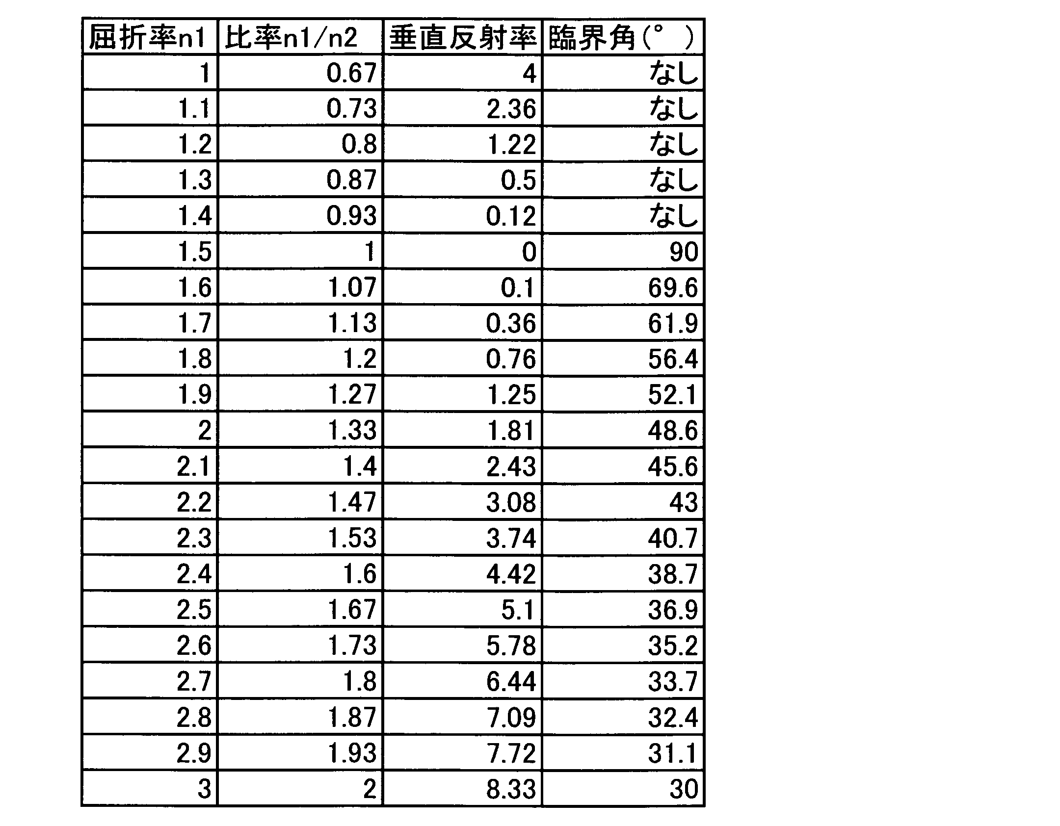
- the reflectance (vertical reflectance) at the interface 6 is as shown in Table 2. As shown in FIG. 3, the interface reflectance when the refractive index ratio n1 / n2 is 1 is zero, and the interface reflectance increases as the ratio n1 / n2 becomes smaller than 1, and the ratio n1 As / n2 becomes larger than 1, the interface reflectance increases.
- the interface reflectance is calculated by the following equation.
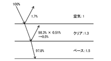
- the refractive index n2 of the base coating film 5 is 1.5, the vertical reflectance at the interface between the base coating film 5 and the clear coating film 6 is 0.51 from the relational expression between the refractive index and the reflectance. %.
- the transmittance to the clear coating film 6 is 98.3%. Since 0.51% of the 98% transmitted light is reflected at the interface between the base coating film 5 and the clear coating film 6, the interface reflectance is 98.3% ⁇ 0.51 ⁇ 0.01 ⁇ 0.00. 50%.
- the refractive index n2 of the base coating film 5 is 1.5, the vertical reflectance at the interface between the base coating film 5 and the clear coating film 6 is 0.83%.
- the transmittance to the clear coating film 6 is 91.8%. Since 0.83% of the 91.8% transmitted light is reflected at the interface between the base coating film 5 and the clear coating film 6, the interface reflectance is 91.8% ⁇ 0.83 ⁇ 0.01 ⁇ 0.76%.
- the refractive index n1 of the clear coating film 6 is 1.2 or more and 1.5 or less
- the ratio n1 / n2 of the refractive index n1 and the refractive index n2 of the base coating film 5 is 0.67 or more and 1 or less. It is a case.
- the clear refractive index n1 of the clear coating film 6 is 1.2 or more and 1.5 or less, as is clear from Table 1, the surface reflectance (vertical reflectance) of the clear coating film 6 is 4% or less. Yes, the light transmittance to the clear coating film 6 is relatively high.
- the refractive index ratio n1 / n2 being 0.67 or more and 1 or less means that the vertical reflectance at the interface between the base coating film 5 and the clear coating film 6 is 4% or less, and the light to the base coating film 5 That is, the transmittance is relatively high.
- the refractive index ratio n1 / n2 being 1 or less means that the refractive index n1 of the clear coating film 6 is lower than the refractive index n2 of the base coating film 5, that is, the base coating film 5 and the clear coating film. That is, total reflection of light does not occur at the interface of the film 6.
- the light transmittance to the base coating film 5 is increased, and as a result, the probability that incident light is in contact with the colorant (pigment 7, glitter material 8) is increased and the color development is vivid. Become. Moreover, since the reflectance at the interface between the base coating film 5 and the clear coating film 6 is low, irregular reflection of light at the interface can be suppressed. Furthermore, since light is not totally reflected at the interface between the lower layer coating film and the upper layer coating film, the brightness does not change greatly depending on the viewing angle of the coating film.
- Example 1 The composition of the top coat film of Example 1 is shown in Table 3.
- the acrylic resin constituting the base coating film 5 is an acrylic resin manufactured by Nippon Paint Co., Ltd. (acid value: 20 mg KOH / g, hydroxyl value: 75 mg KOH / g, number average molecular weight: 5000, solid content 60 mass%) It was adopted.
- As the pigment Mitsubishi Carbon Black # 2650 manufactured by Mitsubishi Chemical Corporation was used.
- the refractive index n2 of the base coating film 5 is 1.5.
- the clear acrylic resin constituting the clear coating film 6 an acrylic resin manufactured by Nippon Paint Co., Ltd. was adopted, and SiO 2 nanoparticles were added in order to adjust the refractive index n1 of the clear coating film 6 low.
- SiO 2 nanoparticles Nano Tek Slurry (SiO 2 solid content 20% by mass) manufactured by CI Kasei Co., Ltd. was employed.
- the refractive index n1 of the clear coating film 6 is 1.4.
- Table 4 shows the composition of the top coat film of Example 2.
- the base refractive index of the coating film 5 in order to n2 1.4, the base paint film 5 to SiO 2 nanoparticles (C. I. Kasei Co., Ltd. Nano Tek Slurry (SiO 2 solid content of 20 mass %)) Is added.
- Table 5 shows the composition of the overcoat film of the comparative example.
- the refractive index n1 of the clear coating film 6 is 1.6 or more and 3.0 or less, and the ratio n1 / n2 between the refractive index n1 and the refractive index n2 of the base coating film 5 is larger than 1 and 1.67.
- the case is as follows.
- the clear refractive index n1 of the clear coating film 6 is 1.6 or more and 3.0 or less. As is clear from Table 1, the surface reflectance (vertical reflectance) of the clear coating film 6 is 5% or more. Yes, the ratio of light entering the base coating film 5 via the clear coating film 6 is reduced. When the refractive index ratio n1 / n2 is larger than 1 and 1.67 or less, the refractive index difference between the two is small.
- the refractive index ratio n1 / n2 being larger than 1 means that when light enters the base coating 5 from the clear coating 6, total reflection of light occurs at the interface between the two coatings.
- the brightness changes depending on the angle at which the coating film is viewed (FF property is obtained), the paint color has a deep feeling, and the surface reflection is strong, so the darkness is calm. Can be obtained.
- Table 6 shows the composition of the top coat film of Example 3.
- the base coating film 5 is the same as in Example 1, and its refractive index n2 is 1.5.
- the clear coating film 6 is different from Example 1 in that ZrO 2 nanoparticles are added instead of SiO 2 nanoparticles in order to adjust the refractive index n1 higher.
- ZrO 2 nanoparticles a ZrO 2 nanoparticle dispersion (ZrO 2 solid content 20% by mass) manufactured by Sumitomo Osaka Cement Co., Ltd. was employed.
- the refractive index n1 of the clear coating film 6 is 1.8.
- Table 7 shows the composition of the top coat film of Example 4.
- the base coating film 5 is made of SiO 2 nanoparticles (Nano Tek Slurry manufactured by CI Kasei Co., Ltd. (SiO 2 solid content 20 mass). %)) Is added.
- the base coating film 5 of the said embodiment is a single layer, you may set the refractive index n2 of an upper base coating-film layer like the said Embodiment 1, 2 by making the base coating film 5 into a two-layer structure. .
- the present invention can be applied to a case in which the base coating film 5 of the top coating film 4 is a transparent color base coating film and the intermediate coating film 3 is formed by a color intermediate coating.
- the refractive index n1 of the color base coating film 5 having transparency as the upper layer coating film and the refractive index n2 of the color intermediate coating film 3 as the lower layer coating film are set as in the first and second embodiments. .
- the intermediate coating film is provided between the undercoat film and the topcoat film, but the intermediate coating film is omitted and the base coating film is directly stacked on the undercoat film.
- the present invention can also be applied to such a laminated coating film.
- a dye may be employed instead of the pigment or together with the pigment.
Landscapes
- Physics & Mathematics (AREA)
- Life Sciences & Earth Sciences (AREA)
- Engineering & Computer Science (AREA)
- Wood Science & Technology (AREA)
- General Physics & Mathematics (AREA)
- Optics & Photonics (AREA)
- Laminated Bodies (AREA)
- Application Of Or Painting With Fluid Materials (AREA)
- Paints Or Removers (AREA)
Abstract
Description
光線が屈折率N0の物質から屈折率N1の物質に垂直入射するときの表面反射率Rは次式で与えられることが知られている。
上記式によれば、空気の屈折率を1とするとき、光が空気から屈折率n1のクリヤ塗膜6に垂直入射するときの表面反射率(垂直反射率)は表1に示すとおりである。図2に示すように、n1が大きくなるに従って表面反射率が大きくなる。

×(ベース塗膜5とクリヤ塗膜6の界面での垂直反射率)
図4にクリヤ塗膜6の屈折率n1=1.3のときの積層塗膜における光の垂直反射率及び透過率の一例を示す。表1によれば、屈折率n1=1.3のクリヤ塗膜6の表面での垂直反射率は1.7%である。また、ベース塗膜5の屈折率n2=1.5であるから、上記屈折率と反射率との関係式から、ベース塗膜5とクリヤ塗膜6の界面での垂直反射率は0.51%である。
本実施形態はクリヤ塗膜6の屈折率n1を1.2以上1.5以下とし、この屈折率n1とベース塗膜5の屈折率n2の比率n1/n2を0.67以上1以下とするケースである。
実施例1の上塗り塗膜の構成を表3に示す。

実施例2の上塗り塗膜の構成を表4に示す。

比較例の上塗り塗膜の構成を表5に示す。

本実施形態はクリヤ塗膜6の屈折率n1を1.6以上3.0以下とし、この屈折率n1とベース塗膜5の屈折率n2の比率n1/n2を1よりも大きく且つ1.67以下とするケースである。
実施例3の上塗り塗膜の構成を表6に示す。

実施例4の上塗り塗膜の構成を表7に示す。

上記実施形態のベース塗膜5は単層であるが、ベース塗膜5を上下二層構造として、上側ベース塗膜層の屈折率n2を上記実施形態1,2のように設定してもよい。
2 下塗り塗膜
3 中塗り塗膜
4 上塗り塗膜
5 ベース塗膜(下層塗膜)
6 クリヤ塗膜(上層塗膜)
7 顔料(着色材)
8 光輝材(着色材)
9 ナノ粒子
Claims (8)
- 着色材を含有する下層塗膜と、該下層塗膜上に積層された上層塗膜とを備えてなる積層塗膜において、
上記上層塗膜の着色材を除く塗膜形成要素の屈折率n1が1.2以上1.5以下であり、
上記上層塗膜の上記屈折率n1と上記下層塗膜の少なくとも表層部における着色材を除く塗膜形成要素の屈折率n2の比率n1/n2が0.67以上1以下であることを特徴とする積層塗膜。 - 請求項1において、
上記上層塗膜の着色材を除く塗膜形成要素は、主成分である樹脂に該樹脂よりも低屈折率のナノ粒子が添加されてなることを特徴とする積層塗膜。 - 被塗物に請求項1に記載の積層塗膜を備えることを特徴とする塗装物。
- 被塗物に請求項2に記載の積層塗膜を備えることを特徴とする塗装物。
- 着色材を含有する下層塗膜と、該下層塗膜上に積層された上層塗膜とを備えてなる積層塗膜において、
上記上層塗膜の着色材を除く塗膜形成要素の屈折率n1が1.6以上3.0以下であり、
上記上層塗膜の上記屈折率n1と上記下層塗膜の少なくとも表層部における着色材を除く塗膜形成要素の屈折率n2の比率n1/n2が1よりも大きく且つ1.67以下であることを特徴とする積層塗膜。 - 請求項5において、
上記上層塗膜の着色材を除く塗膜形成要素は、主成分である樹脂に該樹脂よりも高屈折率のナノ粒子が添加されてなることを特徴とする積層塗膜。 - 被塗物に請求項5に記載の積層塗膜を備えることを特徴とする塗装物。
- 被塗物に請求項6に記載の積層塗膜を備えることを特徴とする塗装物。
Priority Applications (3)
| Application Number | Priority Date | Filing Date | Title |
|---|---|---|---|
| DE112014004985.9T DE112014004985B4 (de) | 2013-10-30 | 2014-10-03 | Mehrlagiger Beschichtungsfilm und beschichteter Artikel |
| US15/032,531 US10118196B2 (en) | 2013-10-30 | 2014-10-03 | Laminated coating film and coated article |
| CN201480056958.0A CN105916683B (zh) | 2013-10-30 | 2014-10-03 | 叠层涂膜及涂装物 |
Applications Claiming Priority (2)
| Application Number | Priority Date | Filing Date | Title |
|---|---|---|---|
| JP2013225127A JP2015085257A (ja) | 2013-10-30 | 2013-10-30 | 積層塗膜及び塗装物 |
| JP2013-225127 | 2013-10-30 |
Publications (1)
| Publication Number | Publication Date |
|---|---|
| WO2015064015A1 true WO2015064015A1 (ja) | 2015-05-07 |
Family
ID=53003650
Family Applications (1)
| Application Number | Title | Priority Date | Filing Date |
|---|---|---|---|
| PCT/JP2014/005061 Ceased WO2015064015A1 (ja) | 2013-10-30 | 2014-10-03 | 積層塗膜及び塗装物 |
Country Status (5)
| Country | Link |
|---|---|
| US (1) | US10118196B2 (ja) |
| JP (1) | JP2015085257A (ja) |
| CN (1) | CN105916683B (ja) |
| DE (1) | DE112014004985B4 (ja) |
| WO (1) | WO2015064015A1 (ja) |
Cited By (3)
| Publication number | Priority date | Publication date | Assignee | Title |
|---|---|---|---|---|
| WO2016079933A1 (ja) * | 2014-11-21 | 2016-05-26 | マツダ株式会社 | 積層塗膜及び塗装物 |
| WO2016079932A1 (ja) * | 2014-11-21 | 2016-05-26 | マツダ株式会社 | 積層塗膜及び塗装物 |
| DE112014004985B4 (de) * | 2013-10-30 | 2024-05-29 | Mazda Motor Corporation | Mehrlagiger Beschichtungsfilm und beschichteter Artikel |
Families Citing this family (3)
| Publication number | Priority date | Publication date | Assignee | Title |
|---|---|---|---|---|
| US11071999B2 (en) * | 2016-07-13 | 2021-07-27 | Kansai Paint Co., Ltd. | Effect pigment dispersion |
| EP3421143A4 (en) * | 2016-09-30 | 2019-07-03 | Mazda Motor Corporation | MULTILAYER COATING FILM AND COATED ARTICLE |
| CN111132771B (zh) * | 2017-09-29 | 2022-05-27 | 关西涂料株式会社 | 多层涂膜形成方法 |
Citations (10)
| Publication number | Priority date | Publication date | Assignee | Title |
|---|---|---|---|---|
| JPH02241577A (ja) * | 1989-03-15 | 1990-09-26 | Toyota Motor Corp | 高深み感塗膜 |
| JPH06254480A (ja) * | 1993-03-05 | 1994-09-13 | Nissan Motor Co Ltd | 高質感塗装方法 |
| JPH1177874A (ja) * | 1997-09-11 | 1999-03-23 | Kimoto & Co Ltd | 印刷物表面保護フィルム |
| JP2005132108A (ja) * | 2003-10-09 | 2005-05-26 | Sk Kaken Co Ltd | 積層体 |
| JP2006007006A (ja) * | 2004-06-22 | 2006-01-12 | Nippon Paint Co Ltd | 複層塗膜形成方法、複層塗膜及び被塗物 |
| JP2007030384A (ja) * | 2005-07-28 | 2007-02-08 | Nisshin Steel Co Ltd | 干渉模様を抑えたクリア塗装ステンレス鋼板 |
| JP2007136362A (ja) * | 2005-11-18 | 2007-06-07 | Kubota Matsushitadenko Exterior Works Ltd | 複合被膜構造及び塗装外装材 |
| JP2007182511A (ja) * | 2006-01-10 | 2007-07-19 | Toray Ind Inc | コーティング材料、その製造方法および光学物品 |
| JP2008012837A (ja) * | 2006-07-07 | 2008-01-24 | Sk Kaken Co Ltd | 積層体 |
| JP2009037064A (ja) * | 2007-08-02 | 2009-02-19 | Panasonic Electric Works Co Ltd | 反射防止基材の製造方法及び反射防止基材 |
Family Cites Families (19)
| Publication number | Priority date | Publication date | Assignee | Title |
|---|---|---|---|---|
| JPS62124160A (ja) * | 1985-11-25 | 1987-06-05 | Mitsubishi Motors Corp | 艶消し塗装の焼付補修方法及び補修用塗料並びにぼかし液 |
| JPH0673656B2 (ja) * | 1987-03-28 | 1994-09-21 | 日本ペイント株式会社 | 塗膜の形成方法 |
| JP2001149855A (ja) * | 1999-09-14 | 2001-06-05 | Toto Ltd | 光触媒性被覆着色物品及びその製造方法 |
| DE10014030A1 (de) * | 2000-03-22 | 2001-09-27 | Bayer Ag | Verfahren zur Verbesserung der Adhäsionsstabilität der Oberfläche von Kunststoffformteilen |
| JP4162545B2 (ja) * | 2003-06-26 | 2008-10-08 | エスケー化研株式会社 | 模様面の形成方法 |
| JP4292020B2 (ja) * | 2003-04-15 | 2009-07-08 | 日本ペイント株式会社 | 意匠性塗膜、意匠性塗膜形成方法および意匠性塗料組成物 |
| JP2005099675A (ja) * | 2003-08-21 | 2005-04-14 | Sony Corp | 塗布型光学積層膜、光学多層膜及び反射スクリーン |
| US7288582B2 (en) * | 2004-04-05 | 2007-10-30 | Ppg Industries Ohio, Inc. | Colored compositions with substrate-hiding materials |
| JP4873974B2 (ja) * | 2006-03-28 | 2012-02-08 | 新日本製鐵株式会社 | プレコート金属板及びその製造方法 |
| JP5030694B2 (ja) | 2006-07-18 | 2012-09-19 | 株式会社日本触媒 | 酸化ジルコニウムナノ粒子 |
| JP2008026658A (ja) * | 2006-07-21 | 2008-02-07 | Fujifilm Corp | 反射防止フィルム、該反射防止フィルムを用いた偏光板及び、該反射防止フィルム又は該偏光板をディスプレイの最表面に用いた画像表示装置 |
| JP4870500B2 (ja) | 2006-09-06 | 2012-02-08 | 株式会社エヌ・ティ・ティ・ドコモ | 通信装置及び通信制御方法 |
| JP2009244382A (ja) | 2008-03-28 | 2009-10-22 | Sharp Corp | 機能性フィルム及び表示装置 |
| PL2113527T3 (pl) | 2008-04-28 | 2014-10-31 | Bayer Ip Gmbh | Odkształcalna folia z powłoką utwardzalną radiacyjnie i wykonane z niej kształtki |
| US9206335B2 (en) | 2008-10-10 | 2015-12-08 | 3M Innovation Properties Company | Silica coating for enhanced hydrophilicity |
| US20100092765A1 (en) | 2008-10-10 | 2010-04-15 | 3M Innovative Properties Company | Silica coating for enhanced hydrophilicity |
| JP2010279899A (ja) * | 2009-06-04 | 2010-12-16 | Nikon Corp | 塗装品 |
| JP2013142793A (ja) * | 2012-01-11 | 2013-07-22 | Dainippon Printing Co Ltd | ハードコートフィルム及びその製造方法、反射防止フィルム |
| JP2015085257A (ja) * | 2013-10-30 | 2015-05-07 | マツダ株式会社 | 積層塗膜及び塗装物 |
-
2013
- 2013-10-30 JP JP2013225127A patent/JP2015085257A/ja active Pending
-
2014
- 2014-10-03 WO PCT/JP2014/005061 patent/WO2015064015A1/ja not_active Ceased
- 2014-10-03 CN CN201480056958.0A patent/CN105916683B/zh active Active
- 2014-10-03 US US15/032,531 patent/US10118196B2/en active Active
- 2014-10-03 DE DE112014004985.9T patent/DE112014004985B4/de active Active
Patent Citations (10)
| Publication number | Priority date | Publication date | Assignee | Title |
|---|---|---|---|---|
| JPH02241577A (ja) * | 1989-03-15 | 1990-09-26 | Toyota Motor Corp | 高深み感塗膜 |
| JPH06254480A (ja) * | 1993-03-05 | 1994-09-13 | Nissan Motor Co Ltd | 高質感塗装方法 |
| JPH1177874A (ja) * | 1997-09-11 | 1999-03-23 | Kimoto & Co Ltd | 印刷物表面保護フィルム |
| JP2005132108A (ja) * | 2003-10-09 | 2005-05-26 | Sk Kaken Co Ltd | 積層体 |
| JP2006007006A (ja) * | 2004-06-22 | 2006-01-12 | Nippon Paint Co Ltd | 複層塗膜形成方法、複層塗膜及び被塗物 |
| JP2007030384A (ja) * | 2005-07-28 | 2007-02-08 | Nisshin Steel Co Ltd | 干渉模様を抑えたクリア塗装ステンレス鋼板 |
| JP2007136362A (ja) * | 2005-11-18 | 2007-06-07 | Kubota Matsushitadenko Exterior Works Ltd | 複合被膜構造及び塗装外装材 |
| JP2007182511A (ja) * | 2006-01-10 | 2007-07-19 | Toray Ind Inc | コーティング材料、その製造方法および光学物品 |
| JP2008012837A (ja) * | 2006-07-07 | 2008-01-24 | Sk Kaken Co Ltd | 積層体 |
| JP2009037064A (ja) * | 2007-08-02 | 2009-02-19 | Panasonic Electric Works Co Ltd | 反射防止基材の製造方法及び反射防止基材 |
Cited By (7)
| Publication number | Priority date | Publication date | Assignee | Title |
|---|---|---|---|---|
| DE112014004985B4 (de) * | 2013-10-30 | 2024-05-29 | Mazda Motor Corporation | Mehrlagiger Beschichtungsfilm und beschichteter Artikel |
| WO2016079933A1 (ja) * | 2014-11-21 | 2016-05-26 | マツダ株式会社 | 積層塗膜及び塗装物 |
| WO2016079932A1 (ja) * | 2014-11-21 | 2016-05-26 | マツダ株式会社 | 積層塗膜及び塗装物 |
| JP2016097594A (ja) * | 2014-11-21 | 2016-05-30 | マツダ株式会社 | 積層塗膜及び塗装物 |
| JP2016097593A (ja) * | 2014-11-21 | 2016-05-30 | マツダ株式会社 | 積層塗膜及び塗装物 |
| US10265727B2 (en) | 2014-11-21 | 2019-04-23 | Mazda Motor Corporation | Layered coating film, and coated article |
| US10370772B2 (en) | 2014-11-21 | 2019-08-06 | Mazda Motor Corporation | Layered coating film, and coated article |
Also Published As
| Publication number | Publication date |
|---|---|
| DE112014004985T5 (de) | 2016-07-28 |
| DE112014004985B4 (de) | 2024-05-29 |
| US20160256893A1 (en) | 2016-09-08 |
| CN105916683B (zh) | 2017-12-01 |
| CN105916683A (zh) | 2016-08-31 |
| US10118196B2 (en) | 2018-11-06 |
| JP2015085257A (ja) | 2015-05-07 |
Similar Documents
| Publication | Publication Date | Title |
|---|---|---|
| CN105916683B (zh) | 叠层涂膜及涂装物 | |
| JP2008100129A (ja) | 塗膜の形成方法および塗膜 | |
| CA2991282C (en) | Multilayer coating film and coated article | |
| CN109715299B (zh) | 叠层涂膜及涂装物 | |
| US20170218206A1 (en) | Multilayer coating film and coated object | |
| CN109789438A (zh) | 叠层涂膜及涂装物 | |
| CN109789439A (zh) | 叠层涂膜及涂装物 | |
| JP2011173943A (ja) | 真珠光沢顔料を用いたインキ | |
| JP5304994B2 (ja) | 薄膜構造 | |
| JP2011153208A (ja) | 真珠光沢顔料を用いたインキ | |
| US10265727B2 (en) | Layered coating film, and coated article | |
| JP6562148B2 (ja) | 積層塗膜及び塗装物 | |
| US10370772B2 (en) | Layered coating film, and coated article | |
| JP6156027B2 (ja) | 積層塗膜及び自動車の車体 | |
| JP6156334B2 (ja) | 積層塗膜及び塗装物 | |
| KR20220120231A (ko) | 데코 필름의 제조 방법 | |
| JP6156335B2 (ja) | 積層塗膜及び塗装物 | |
| JP2007125822A (ja) | 積層塗膜および塗膜形成方法 | |
| WO2024116735A1 (ja) | 積層塗膜及び塗装物 | |
| JP2005161275A (ja) | 高彩度積層塗膜および塗膜形成方法 | |
| JP2007105602A (ja) | 積層塗膜および塗膜形成方法 | |
| JP2005161276A (ja) | 高彩度積層塗膜および塗膜形成方法 | |
| JP2001070872A (ja) | クロムメッキ面のクリア塗装方法 | |
| TH93893A (th) | แผ่นตกแต่ง | |
| TH63435B (th) | แผ่นตกแต่ง |
Legal Events
| Date | Code | Title | Description |
|---|---|---|---|
| 121 | Ep: the epo has been informed by wipo that ep was designated in this application |
Ref document number: 14857973 Country of ref document: EP Kind code of ref document: A1 |
|
| WWE | Wipo information: entry into national phase |
Ref document number: 15032531 Country of ref document: US |
|
| NENP | Non-entry into the national phase |
Ref country code: DE |
|
| WWE | Wipo information: entry into national phase |
Ref document number: 1120140049859 Country of ref document: DE Ref document number: 112014004985 Country of ref document: DE |
|
| 122 | Ep: pct application non-entry in european phase |
Ref document number: 14857973 Country of ref document: EP Kind code of ref document: A1 |