WO2015060448A1 - 作業車両および回転灯 - Google Patents
作業車両および回転灯 Download PDFInfo
- Publication number
- WO2015060448A1 WO2015060448A1 PCT/JP2014/078408 JP2014078408W WO2015060448A1 WO 2015060448 A1 WO2015060448 A1 WO 2015060448A1 JP 2014078408 W JP2014078408 W JP 2014078408W WO 2015060448 A1 WO2015060448 A1 WO 2015060448A1
- Authority
- WO
- WIPO (PCT)
- Prior art keywords
- rod
- rotating lamp
- shaped portion
- disposed
- shaped
- Prior art date
Links
Images


Classifications
-
- E—FIXED CONSTRUCTIONS
- E02—HYDRAULIC ENGINEERING; FOUNDATIONS; SOIL SHIFTING
- E02F—DREDGING; SOIL-SHIFTING
- E02F9/00—Component parts of dredgers or soil-shifting machines, not restricted to one of the kinds covered by groups E02F3/00 - E02F7/00
- E02F9/26—Indicating devices
-
- B—PERFORMING OPERATIONS; TRANSPORTING
- B60—VEHICLES IN GENERAL
- B60Q—ARRANGEMENT OF SIGNALLING OR LIGHTING DEVICES, THE MOUNTING OR SUPPORTING THEREOF OR CIRCUITS THEREFOR, FOR VEHICLES IN GENERAL
- B60Q1/00—Arrangement of optical signalling or lighting devices, the mounting or supporting thereof or circuits therefor
- B60Q1/02—Arrangement of optical signalling or lighting devices, the mounting or supporting thereof or circuits therefor the devices being primarily intended to illuminate the way ahead or to illuminate other areas of way or environments
- B60Q1/24—Arrangement of optical signalling or lighting devices, the mounting or supporting thereof or circuits therefor the devices being primarily intended to illuminate the way ahead or to illuminate other areas of way or environments for lighting other areas than only the way ahead
-
- B—PERFORMING OPERATIONS; TRANSPORTING
- B60—VEHICLES IN GENERAL
- B60Q—ARRANGEMENT OF SIGNALLING OR LIGHTING DEVICES, THE MOUNTING OR SUPPORTING THEREOF OR CIRCUITS THEREFOR, FOR VEHICLES IN GENERAL
- B60Q1/00—Arrangement of optical signalling or lighting devices, the mounting or supporting thereof or circuits therefor
- B60Q1/26—Arrangement of optical signalling or lighting devices, the mounting or supporting thereof or circuits therefor the devices being primarily intended to indicate the vehicle, or parts thereof, or to give signals, to other traffic
- B60Q1/2611—Indicating devices mounted on the roof of the vehicle
-
- B—PERFORMING OPERATIONS; TRANSPORTING
- B60—VEHICLES IN GENERAL
- B60Q—ARRANGEMENT OF SIGNALLING OR LIGHTING DEVICES, THE MOUNTING OR SUPPORTING THEREOF OR CIRCUITS THEREFOR, FOR VEHICLES IN GENERAL
- B60Q1/00—Arrangement of optical signalling or lighting devices, the mounting or supporting thereof or circuits therefor
- B60Q1/26—Arrangement of optical signalling or lighting devices, the mounting or supporting thereof or circuits therefor the devices being primarily intended to indicate the vehicle, or parts thereof, or to give signals, to other traffic
- B60Q1/2615—Arrangement of optical signalling or lighting devices, the mounting or supporting thereof or circuits therefor the devices being primarily intended to indicate the vehicle, or parts thereof, or to give signals, to other traffic mounted on the vehicle body, e.g. with magnets
-
- B—PERFORMING OPERATIONS; TRANSPORTING
- B62—LAND VEHICLES FOR TRAVELLING OTHERWISE THAN ON RAILS
- B62D—MOTOR VEHICLES; TRAILERS
- B62D33/00—Superstructures for load-carrying vehicles
- B62D33/06—Drivers' cabs
- B62D33/0617—Drivers' cabs for tractors or off-the-road vehicles
-
- E—FIXED CONSTRUCTIONS
- E02—HYDRAULIC ENGINEERING; FOUNDATIONS; SOIL SHIFTING
- E02F—DREDGING; SOIL-SHIFTING
- E02F9/00—Component parts of dredgers or soil-shifting machines, not restricted to one of the kinds covered by groups E02F3/00 - E02F7/00
- E02F9/08—Superstructures; Supports for superstructures
- E02F9/0858—Arrangement of component parts installed on superstructures not otherwise provided for, e.g. electric components, fenders, air-conditioning units
-
- E—FIXED CONSTRUCTIONS
- E02—HYDRAULIC ENGINEERING; FOUNDATIONS; SOIL SHIFTING
- E02F—DREDGING; SOIL-SHIFTING
- E02F9/00—Component parts of dredgers or soil-shifting machines, not restricted to one of the kinds covered by groups E02F3/00 - E02F7/00
- E02F9/16—Cabins, platforms, or the like, for drivers
- E02F9/163—Structures to protect drivers, e.g. cabins, doors for cabins; Falling object protection structure [FOPS]; Roll over protection structure [ROPS]
-
- B—PERFORMING OPERATIONS; TRANSPORTING
- B60—VEHICLES IN GENERAL
- B60Q—ARRANGEMENT OF SIGNALLING OR LIGHTING DEVICES, THE MOUNTING OR SUPPORTING THEREOF OR CIRCUITS THEREFOR, FOR VEHICLES IN GENERAL
- B60Q2800/00—Features related to particular types of vehicles not otherwise provided for
- B60Q2800/20—Utility vehicles, e.g. for agriculture, construction work
Definitions
- the present invention relates to a work vehicle and a rotating lamp.
- Some hydraulic excavators which are examples of work vehicles, have the function of a bent jib type mobile crane.
- a rotating lamp For example, as shown in FIG. 1 of Patent Document 1, the rotating lamp is disposed on the top plate of the cab.
- the conventional work vehicle has the following problems. Depending on the height of the cab of the excavator, the installation of a rotating light on the top of the cab may exceed the transportation regulation height. In this case, since it is necessary to remove the rotating lamp from the top plate during transportation and to reattach it during work, improvement in handling when the rotating lamp is attached / detached is required.
- the objective of this invention is providing the work vehicle provided with the revolving light and revolving light which are easy to handle at the time of attachment or detachment.
- a work vehicle is a work vehicle including a work machine, and includes a cab and a rotating lamp.
- the cab has a top plate provided at the top, and first and second side surfaces provided on the left and right sides.
- the revolving light is detachably disposed on the top plate of the cab.
- the revolving light has a revolving light main body, a mounting part, and a grip part.
- the attachment portion is provided on the lower side of the rotating lamp body and attaches the rotating lamp body to the top plate.
- the gripping portion is a portal shape and is fixed to the mounting portion.
- the gripping portion has a first rod-shaped portion, a second rod-shaped portion, and a third rod-shaped portion.
- the first rod-like portion and the second rod-like portion are formed upward from the attachment portion.
- the 1st rod-shaped part is arranged ahead of the 2nd rod-shaped part.
- the second rod-shaped portion is disposed on the rear side of the rotating lamp main body, and is disposed on the first side surface side with respect to the first rod-shaped portion.
- the third rod-like portion is disposed on the upper side of the rotating lamp body as viewed from the side perpendicular to the longitudinal direction.
- the position of the top plate is high, so an operator often supports the cab with one hand and attaches the rotating lamp using only the other hand. At this time, the operator can easily apply a force in the vertical direction to the rotating lamp by gripping the first rod-shaped portion or the second rod-shaped portion formed upward. Therefore, even when the rotating lamp is mounted on the top plate of the cab with one hand, it is easy to prevent the rotating lamp from swinging up and down, and it is easy to attach and detach.
- the 3rd rod-shaped part of a holding part is provided above the rotating lamp main body, it is reduced that the light of a rotating lamp is interrupted by the 3rd rod-shaped part.
- the grip portion is a portal shape, the third rod-shaped portion can be gripped when the rotating lamp is removed from the cab, so that it is easy to carry.
- the grip portion is a portal shape, the strength of the grip portion can be ensured.
- the second rod-shaped portion is arranged on the rear side of the rotating lamp main body in this way, it is possible to prevent an obstacle from colliding with the rotating lamp main body from the rear.
- a work vehicle according to a second aspect of the present invention is the work vehicle according to the first aspect of the present invention, wherein a part of the third rod-shaped portion overlaps the rotating lamp main body in plan view.
- the grip portion so as to straddle the rotating lamp main body, the first rod-shaped portion or the second rod-shaped portion can be disposed at a position closer to the center of gravity of the rotating lamp. Therefore, the operator can more easily prevent the rotating lamp from swinging up and down.
- a work vehicle is the work vehicle according to the second aspect, wherein the rotating lamp body includes a base member, a light source, and a cover member.
- the base member is fixed to the mounting portion.
- the light source is disposed inside the base member.
- the cover member covers the light source from above and is detachably attached to the base member.
- a predetermined interval through which the cover member passes when the cover member is removed from the base member is formed between the third rod-shaped portion and the cover member.
- a work vehicle is the work vehicle according to the first aspect of the present invention, wherein the work implement is disposed on the side of the first side surface of the cab.
- the revolving lamp is disposed at the end of the top plate on the second side surface side.
- the first rod-shaped portion is located on the second side surface side with respect to the rotating lamp main body. As viewed from the second side surface, a part of the first bar-like portion overlaps the rotating lamp main body.
- a 1st rod-shaped part can be arrange
- a work vehicle is the work vehicle according to the first aspect of the present invention, further comprising a base portion that is fixed to the top plate and to which the attachment portion is detachably attached.
- the base part has an engaging part and a guide part.
- the engagement portion can be engaged with the attachment portion.
- the guide portion guides the mounting portion to a position where it can be engaged by the engaging portion, and has a restricting portion.
- the restricting portion restricts the movement of the attachment portion in a state where the restricting portion is engaged with the engaging portion after being guided.
- the attachment part has an engaged part and a restricted part.
- the engaged portion is engaged with the engaging portion.
- the regulated portion is provided on the opposite side of the engaged portion across the rotating lamp body.
- the engaging portion In a state where the engaging portion is engaged with the engaged portion, the engaged portion is biased downward, whereby the restricted portion is biased upward to contact the restricting portion and the mounting portion becomes the base portion. It is fixed.
- the mounting part can be fixed to the base part simply by disposing the mounting part on the base part along the guide part and engaging the base part and the mounting part. It can be attached to the top plate.
- the rotating lamp can be easily detached from the top plate simply by releasing the engagement.
- a work vehicle according to a sixth aspect of the present invention is the work vehicle according to the fifth aspect of the present invention, wherein the work implement is disposed on the side of the first side surface of the cab.
- the revolving lamp is disposed at the end of the top plate on the second side surface side.
- the engaging portion and the engaged portion are provided on the second side surface side of the rotating lamp main body.
- a work vehicle according to a seventh aspect of the present invention is the work vehicle according to the sixth aspect of the present invention, wherein the attachment portion further has a fixing portion fixed to the base portion by a magnetic force on the lower surface thereof.
- a part of the third rod-shaped portion overlaps the rotating lamp main body as viewed from above.
- a part of the first bar-like portion overlaps the rotating lamp main body.
- the engaging portion and the engaged portion are disposed at substantially the center of the rotating lamp main body in the front-rear direction.
- the first rod-shaped portion is disposed outside the rotating lamp main body and ahead of the engaging portion.
- the second rod-shaped portion is disposed on the rear side of the rotating lamp main body.
- a rotating lamp according to an eighth aspect of the present invention is a rotating lamp that is detachably disposed on a top plate provided on an upper part of a cab of a work vehicle, and includes a rotating lamp main body, a mounting portion, and a gripping portion. is doing.
- the attachment portion is provided on the lower side of the rotating lamp body and attaches the rotating lamp body to the top plate.
- the gripping part is a portal type and is fixed to the attachment part.
- the gripping portion has a first rod-shaped portion, a second rod-shaped portion, and a third rod-shaped portion. The first rod-like portion and the second rod-like portion are formed upward from the attachment portion.
- the third rod-shaped portion connects between the first rod-shaped portion and the second rod-shaped portion.
- a part of the third rod-shaped part overlaps the rotating lamp main body in plan view.
- the grip portion so as to straddle the rotating lamp main body, the first rod-shaped portion or the second rod-shaped portion can be disposed at a position closer to the center of gravity of the rotating lamp. Therefore, the operator can more easily prevent the rotating lamp from swinging up and down, and can easily attach and detach the rotating lamp to and from the top plate.
- the work vehicle provided with the revolving light and revolving light which are easy to handle at the time of attachment or detachment can be provided.
- FIG. 1 is an external perspective view of a hydraulic excavator according to an embodiment of the present invention.
- the perspective view which shows the rotary lamp vicinity of the hydraulic shovel shown in FIG. The perspective view which shows the state which looked at the rotary lamp and base part of FIG. 2 from the left back side.
- FIG. 1 is a diagram showing a hydraulic excavator 100 according to an embodiment of the present invention.
- the hydraulic excavator 100 includes a vehicle body 1, a work machine 4, and a rotating lamp 10.
- the vehicle body 1 includes a traveling body 2 and a turning body 3.
- the traveling body 2 includes a pair of traveling devices 2a and 2b. Each traveling device 2a, 2b has crawler belts 2d, 2e, and the crawler belts 2d, 2e are driven by the driving force from the engine to cause the excavator 100 to travel.
- the swivel body 3 is placed on the traveling body 2.
- the swivel body 3 is provided so as to be turnable with respect to the traveling body 2.
- a cab 5 as a cab is provided at the front left side position of the revolving structure 3.
- the front-rear direction means the front-rear direction of the cab 5. Furthermore, the front-rear direction of the vehicle body 1 is assumed to coincide with the front-rear direction of the cab 5, that is, the revolving structure 3. Moreover, the left-right direction or the side means the vehicle width direction of the vehicle main body 1.
- the forward direction is indicated by arrow F
- the backward direction is indicated by arrow B
- the left direction is indicated by arrow L
- the right direction is indicated by arrow R.
- the revolving unit 3 includes a fuel tank, an engine, and the like, and a counterweight 6 is provided behind the revolving unit 3.
- the work machine 4 includes a boom 7, an arm 8, and an excavation bucket 9, and is attached to the front center position of the swing body 3. Specifically, the work machine 4 is disposed on the right side of the right side surface 5 a of the cab 5.
- a base end portion of the boom 7 is rotatably connected to the revolving structure 3. Further, the distal end portion of the boom 7 is rotatably connected to the proximal end portion of the arm 8.
- a distal end portion of the arm 8 is rotatably connected to the excavation bucket 9.
- hydraulic cylinders (not shown) are arranged so as to correspond to the boom 7, the arm 8 and the excavation bucket 9, respectively. The working machine 4 is driven by driving these hydraulic cylinders. Thereby, operations such as excavation are performed.
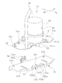
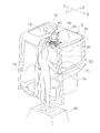
- FIG. 2 is a perspective view showing the vicinity of the rotating lamp 10 of the present embodiment.
- the base part 50 is being fixed to the upper surface of the top plate 5b, and the rotating light 10 is being fixed to the base part 50 so that attachment or detachment is possible. That is, the rotating lamp 10 is attached to the top plate 5b via the base unit 50.
- the rotating lamp 10 includes a rotating lamp main body 20 that emits light, an attachment portion 30 that attaches the rotating lamp main body 20 to the base portion 50, and a grip portion 40 that an operator holds when attaching the attachment portion 30 to the base portion 50. And have.
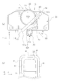
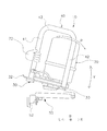
- FIG. 3 is a perspective view showing the rotating lamp 10 and the base part 50 as viewed from the rear side of the left side surface 5c.
- the rotating lamp main body 20 has a substantially cylindrical outer diameter, and includes a base member 21, a bulb 22, and a cover member 23.
- the base member 21 has a bottomed cylindrical shape with an upper opening, and is fixed to the upper surface of the attachment portion 30.
- the bulb 22 is a light source and is disposed in the vicinity of the center of the base member 21 and is replaced when the lifetime is reached.
- the cover member 23 is detachably attached to the base member 21 so as to cover the valve 22 from above.
- a reflector or the like is provided around the bulb 22.
- FIG. 3 shows a connector 24 connected to a wiring routed from the vehicle body 1 in order to supply electricity to the rotating lamp body 20.
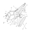
- FIG. 4 is a perspective view showing a state in which the rotating lamp 10 is detached from the base 50, and is a view seen from below the left side surface 5c.
- the attachment part 30 includes a support part 31, an engaged part 32, a regulated part 33, a first positioning protrusion 34, a second positioning protrusion 35, and a first contact part 36.
- the support portion 31 is a plate-like member in which a step is formed, and a first plate-like portion 31 a in which the base member 21 is disposed on the upper side and a front side of the first plate-like portion 31 a. It has the 2nd plate-shaped part 31b provided, and the 3rd plate-shaped part 31c provided in the back side of the 1st plate-shaped part 31a.
- the base member 21 of the rotating lamp main body 20 is disposed on the upper surface of the first plate-like portion 31a. Specifically, the base member 21 is disposed via a plurality of pedestals 311a (see FIG. 3). As shown in FIG. 4, the base member 21 is fixed from the lower surface of the first plate-like portion 31a with a bolt 60 or the like.
- the first contact portion 36 is provided on the lower surface of the second plate-shaped portion 31b. As shown in FIG. 4, the first contact portion 36 is formed by bending a plate-like member and has a contact plane 36 a that contacts the base portion 50.
- the first positioning protrusion 34 is formed to protrude downward from the rear side of the contact flat surface 36a.
- the first positioning protrusion 34 is formed so as to extend in the left-right direction and to extend downward as it goes from left to right.
- a first magnet 38 is disposed on the right side of the first contact portion 36.
- a second contact portion 37 is provided on the lower surface of the third plate-like portion 31c.
- the second contact portion 37 is formed by bending a plate-like member as shown in FIG. 4, and the second contact portion 37 has a contact plane 37 a that contacts the base portion 50. Yes.
- the second positioning protrusion 35 is formed so as to protrude downward from the rear side of the contact plane 37a.
- the second positioning protrusion 35 is formed so as to extend in the left-right direction and to extend downward as it goes from left to right.
- a second magnet 39 is disposed on the right side of the second contact portion 37.
- the engaged portion 32 is provided on the left side surface 5c side of the first plate-like portion 31a. Specifically, the engaged portion 32 protrudes from the edge 311 formed downward from the left end of the first plate-like portion 31a toward the left side surface 5c.
- FIG. 5 is a perspective view of the state shown in FIG. 4 as viewed from above the right side surface 5a.
- the regulated portion 33 is provided below the first plate-like portion 31a. More specifically, a pedestal 311b is provided on the lower surface of the first plate-like portion 31a, and the regulated portion 33 is formed so as to protrude from the lower side of the pedestal 311b to the right side.
- the regulated portion 33 is a plate-like member, and is provided substantially in parallel with the first plate-like portion 31a with a distance from the first plate-like portion 31a by the height of the pedestal 311b.
- the base part 50 includes a base body 51, a lock body 52, and a guide part 53.
- the base body 51 is a substantially plate-like member, and is formed of metal.
- a plurality of through holes 51 h are formed in the base body 51, and the base 50 is fastened to the top plate 5 b of the cab 5 by fastening the through holes 51 h with bolts or the like with nuts. Fixed.
- FIG. 6 is a perspective view showing the rotating lamp 10 and the base part 50 as viewed from the front lower side of the left side surface 5c.
- the base body 51 is formed with a first through groove 51 a and a second through groove 51 b formed in the left-right direction.
- the first positioning protrusion 34 described above is fitted into the first through groove 51a, and the second positioning protrusion 35 described above is inserted into the second through groove 51b. Fits.
- the base body 51 has an edge 511 formed downward from the end on the left side surface 5 c side.
- a central portion 511a in the front-rear direction of the edge portion 511 protrudes toward the left side surface 5c, and the lock body 52 is attached to the central portion 511a.
- the lock body 52 constitutes a fastener (also referred to as a snap lock or a snap lock) together with the engaged portion 32 of the mounting portion 30 described above.
- the lock body 52 includes a hook 521 that engages with the engaged portion 32 and an operation lever 522. The hook 521 is engaged with the engaged portion 32 by moving the operation lever 522 downward after the hook 521 is hooked on the engaged portion 32 of the attachment portion 30.
- the guide portion 53 is provided at a position facing the lock body 52 of the base body 51 (the center in the front-rear direction of the end on the right side surface 5a side), and as shown in FIG. 532.
- the through hole 531 is formed in the base body 51.
- the restricting portion 532 is formed so as to cover the upper side of the through-hole 531, and is attached to the base body 51 with the front end portion 532 a and the rear end portion 532 b, and the front end portion 532 a
- a central portion 532 c between the end portions 532 b is located above the through hole 531.
- the front end portion 532 a is located on the front side of the through hole 531, and the rear end portion 532 b is located on the rear side of the through hole 531.
- the central portion 532c is formed at a position higher than the upper surface of the base body 51, and a gap 533 is formed between the base body 51 and the central portion 532c (see FIG. 12 described later).
- the gripping portion 40 is a portal shape and is formed by bending a single bar-shaped member. As shown in FIG. 3, the grip portion 40 includes a first rod-like portion 41 formed upward from the attachment portion 30, a second rod-like portion 42 formed upward from the attachment portion 30, and a first It has the 3rd rod-shaped part 43 which connects the upper end 41a of the rod-shaped part 41, and the upper end 42a of the 2nd rod-shaped part 42. As shown in FIG. Fig.7 (a) is the top view which looked at the rotary lamp 10 and the base part 50 from upper direction. FIG. 8 is a side view of the rotating lamp 10 and the base 50 as viewed from the left side 5c side.
- the first rod-like portion 41 is disposed on the outer side in the left direction of the rotating lamp body 20, and a part of the first rod-like portion 41 is seen from the left side as shown in FIG. It overlaps with the rotating lamp body 20 in a side view. Further, the first rod-like portion 41 is disposed in front of the engaged portion 32 and is disposed in front of the central axis 20 a of the rotating lamp main body 20. As shown in FIG. 4, the lower end 41b of the first rod-like portion 41 is located on the left side of the edge portion 311 and the side surface of the lower end 41b and the edge portion 311 are connected by welding. In FIG. 4, the connecting portion is shown as P1.
- the 2nd rod-shaped part 42 is provided in the rear side of the rotary lamp main body 20 as shown to Fig.7 (a), and as shown in FIG. 3, the lower end 42b is connected to the upper surface of the 3rd plate-shaped part 31c. Has been. As shown in FIG. 7A, the second rod-shaped portion 42 is located on the right side (inside the work vehicle) with respect to the center shaft 20a, and a part of the second rod-shaped portion 42 is rotated as viewed from the rear. It overlaps with the lamp body 20.
- the third rod-shaped portion 43 is provided horizontally so as to connect the upper end 41 a of the first rod-shaped portion 41 and the upper end 42 a of the second rod-shaped portion 42.
- the third rod-shaped portion 43 is disposed at a position higher than the height of the rotating lamp main body 20.
- the third rod-like portion 43 is disposed so as to partially overlap the rotating lamp main body 20 and to be shifted to the left rear from the central axis 20a as viewed from above (in plan view). ing.
- the longitudinal direction of the third rod-shaped portion 43 is an arrow E, FIG.
- FIG. 7B is a side view of the vicinity of the third rod-shaped portion 43 viewed from the side perpendicular to the longitudinal direction (arrow E).
- the direction perpendicular to the longitudinal direction is the directions of arrows G and H shown in FIG.
- the arrow G direction is the diagonally backward left direction
- the arrow H direction is the diagonally forward right direction. That is, FIG. 7B is a side view of the vicinity of the third rod-shaped portion 43 along the arrow G direction.
- the third rod-like portion 43 is disposed on the upper side of the rotating lamp main body 20 when viewed from the side perpendicular to the longitudinal direction.
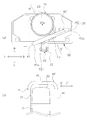
- FIG. 9 is a view of the rotating lamp 10 as viewed from the diagonally forward left, and is a view in which the first rod-like portion 41 is omitted.
- a space S is formed between the rotating lamp 10 and the third rod-like portion 43, and this space S passes through the cover member 23 when the cover member 23 is removed when the bulb 22 is replaced.
- This is a space (see arrow T).
- the grip portion 40 is provided so as to surround the rotating lamp body 20 as in the present embodiment. Even so, the cover member 23 can be removed and the valve 22 can be easily replaced.
- the removed cover member 23 is indicated by a two-dot chain line.
- FIG. 10 is a diagram illustrating a state of an operator who is mounting the rotating lamp 10 on the top plate 5 b of the cab 5.
- the worker 70 rides on a platform 80 such as a stepladder, grips the vicinity of the rear end of the left side surface 5 c of the cab 5 with the right hand 71, and supports the body with the left hand 72. Is attached to the base unit 50.
- the base part 50 is being fixed to the top plate 5b as mentioned above.
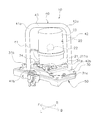
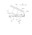
- FIG. 11 is a view of the state in which the rotating lamp 10 is attached to the base unit 50 as viewed from the rear. As shown in FIG. 11, the worker 70 holds the first rod-like portion 41 of the rotating lamp 10 and lowers the regulated portion 33 side of the rotating lamp 10 below the engaged portion 32 side. The regulated portion 33 is inserted into the gap 533 of the guide portion 53.
- FIG. 12 is an enlarged cross-sectional view showing a state where the restricted portion 33 is inserted into the gap 533 of the guide portion 53. As shown in FIG. 12, since the through hole 531 is formed on the lower side of the restricting portion 532, the tip of the restricted portion 33 can be inserted into the through hole 531. Easy to plug into.
- the first rod-like portion 41 is provided in the vertical direction, it is easy to adjust the position of the rotating lamp 10 in the vertical direction (see arrow Y in FIG. 11). Further, as described with reference to FIG. 8, the first rod-like portion 41 is provided closer to the center axis 20 a of the rotating lamp body 20, and therefore the first rod-like portion 41 is provided at a position close to the center of gravity of the rotating lamp 10. This makes it easier to adjust the position of the rotating lamp 10 in the direction of the arrow Y.
- the worker 70 makes the left side of the rotating lamp 10 downward (arrow Q) with the end 532e as a rotation fulcrum in a state where the restricted portion 33 is in contact with the left end 532e (see FIG. 12) of the restricting portion 532. ) And the rotating lamp 10 is placed at the mounting position of the base unit 50. At this time, the contact flat surface 36a of the first contact portion 36 of the attachment portion 30 and the contact flat surface 27a of the second contact portion 37 abut against the base body 51 of the base portion 50, and the first magnet 38 and The second magnet 39 is fixed to the base body 51 by magnetic force (see FIG. 4).
- the first positioning protrusion 34 fits in the first through groove 51a and the second positioning protrusion 35 fits in the second through groove 51b. Like that. Thereby, positioning can be performed more accurately. Further, since the first positioning protrusion 34 and the second positioning protrusion 35 are formed to have a length that extends downward toward the end 532e as the rotation fulcrum, the first through groove 51a and the second through groove 51b are formed. Easy to fit into.
- the hook 521 of the lock body 52 is hooked on the engaged portion 32 and the operation lever 522 is lowered to engage the hook 521 with the engaged portion 32, and the mounting portion to which the rotating lamp main body 20 is fixed. 30 is fixed to the base 50. It can be said that the above-described mounting position is a position where the hook 521 can be hooked on the engaged portion 32 and the operation lever 522 can be lowered, that is, an engageable position.
- FIG. 13 is a perspective view of the rotating lamp 10 attached to the base unit 50 as viewed from the right front.
- the restricted portion 33 is disposed below the restricting portion 532.
- the hook 521 is hooked on the engaged portion 32 and the operation lever 522 is moved downward to enter the engaged state.
- a downward force is applied to the engaged portion 32 side by the lock body 52 (see arrow D).
- an upward force is applied to the restricted portion 33 located on the opposite side of the engaged portion 32 across the rotating lamp main body 20, but the restricted portion 33 is restricted above the restricted portion 33. Since the portion 532 is located, the restricted portion 33 comes into contact with the restricting portion 532 and its movement is restricted. Thereby, the rotary lamp 10 is fixed to the base part 50.
- the mounting portion 30 Since the first magnet 38 and the second magnet 39 are provided on the lower surface of the mounting portion 30, the mounting portion 30 is fixed to the base body 51 by the magnetic force of the first magnet 38 and the second magnet 39. . Therefore, in order to fix the attachment part 30 to the base part 50 with the lock body 52 using the left hand 72, even if the left hand 72 is once separated from the grip part 40, the rotating lamp 10 can be prevented from dropping unexpectedly.
- a hydraulic excavator 100 (an example of a work vehicle) according to the present embodiment is a work vehicle including a work machine 4, and includes a cab 5 and a rotating lamp 10.
- the cab 5 has a top plate 5b provided at the top, a left side surface 5c (an example of a second side surface), and a right side surface 5a (an example of a first side surface) provided on the left and right sides.
- the rotating lamp 10 is detachably disposed on the top plate 5b of the cab 5.
- the revolving lamp 10 has a revolving lamp main body 20, a mounting portion 30, and a gripping portion 40.
- the attachment portion 30 is provided on the lower side of the rotating lamp body 20 and attaches the rotating lamp body 20 to the top plate 5b.
- the grip portion 40 is a portal shape and is fixed to the attachment portion 30, and includes a first rod-shaped portion 41, a second rod-shaped portion 42, and a third rod-shaped portion 43.
- the first rod-like portion 41 and the second rod-like portion 42 are formed upward from the attachment portion 30.
- the third rod-shaped portion 43 connects between the first rod-shaped portion 41 and the second rod-shaped portion 42.
- the first rod-shaped portion 41 is disposed in front of the second rod-shaped portion 42.
- the 2nd rod-shaped part 42 is arrange
- the third rod-like portion 43 is located on the upper side of the rotating lamp body 20 when viewed from the side perpendicular to the longitudinal direction (arrow E direction) (viewed along the arrow G direction). Has been placed.
- the rotating lamp 10 When the rotating lamp 10 is mounted on the top plate 5b of the cab 5, the position of the top plate 5b is high, so that the operator 70 supports the cab 5 with the right hand 71 and the other left hand as shown in FIG. In many cases, the rotating lamp 10 is attached using only 72. At that time, the operator 70 can easily apply force to the rotating lamp 10 in the vertical direction (see arrow Y in FIG. 11) by gripping the first rod-shaped portion 41 formed upward. Therefore, even when the rotating lamp 10 is mounted on the top plate 5b of the cab 5 with one hand, it is easy to prevent the rotating lamp 10 from shaking in the vertical direction (see arrow Y in FIG. 11), and it is easy to attach and detach.
- grip part 40 is provided above the rotating lamp main body 20, it is reduced that the light of the rotating lamp main body 20 is interrupted
- the grip portion 40 is a portal shape, the third rod-shaped portion 43 can be gripped when the rotating lamp 10 is detached from the cab 5, so that it is easy to carry.
- the grip portion 40 is a portal shape, the strength of the grip portion 40 can be ensured.
- the second rod-like portion 42 is arranged on the rear side of the rotating lamp main body 20 in this way, it is possible to prevent an obstacle from colliding with the rotating lamp main body 20 from the rear.
- the rotary lamp main body 20 includes a base member 21, a bulb 22 (an example of a light source), and a cover member 23.
- the base member 21 is fixed to the attachment portion 30.
- the valve 22 is disposed inside the base member 21.
- the cover member 23 covers the valve 22 from above and is detachably attached to the base member 21.
- a predetermined interval S through which the cover member 23 passes when the cover member 23 is removed from the base member 21 is formed between the third rod-shaped portion 43 and the cover member 23 as shown in FIG.
- the cover member 23 is used as a base even if the grip portion 40 is provided so as to surround the rotating lamp main body 20. Since the member 21 can be easily attached and detached, the valve 22 can be easily replaced.
- the work implement 4 is disposed on the side of the right side surface 5 a of the cab 5.
- the rotating lamp 10 is arranged at the end of the top plate 5b on the left side surface 5c side.
- the first rod-like portion 41 is located on the left side surface 5c side with respect to the rotating lamp main body 20. As viewed from the left side surface 5c side (viewed from the left side), a part of the first rod-shaped portion 41 overlaps the rotating lamp main body 20.
- the rotating lamp 10 is disposed above the left side surface 5c of the cab 5 on the opposite side to the work machine 4, the worker 70 does not have to enter the inside of the excavator 100.
- the rotating lamp 10 can be attached from the outside.
- the first rod-shaped portion 41 can be disposed closer to the rotating lamp main body 20. That is, since the first rod-like portion 41 can be disposed at a position closer to the center of gravity of the rotating lamp 10, the operator 70 can more easily prevent the rotating lamp 10 from swinging in the vertical direction (Y direction).
- the 1st rod-shaped part 41 is located in the left side 5c side rather than the rotating lamp main body 20, it can prevent that an obstruction collides with the rotating lamp main body 20 from the left side 5c side.
- the hydraulic excavator 100 further includes a base portion 50 that is fixed to the top plate 5b and to which the attachment portion 30 is detachably attached.
- the base unit 50 includes a lock body 52 (an example of an engagement unit) and a guide unit 53.
- the lock body 52 can be engaged with the attachment portion 30.
- the guide part 53 guides the attachment part 30 to a position where it can be engaged by the lock body 52, and has a restriction part 532.
- the restricting portion 532 restricts the movement of the attachment portion 30 in a state where the restricting portion 532 is engaged with the lock main body 52 after being guided.
- the attachment part 30 has an engaged part 32 and a restricted part 33. The engaged portion 32 is engaged with the lock body 52.
- the regulated portion 33 is provided on the opposite side of the engaged portion 32 with the rotating lamp main body 20 interposed therebetween.
- the engaged portion 32 is biased downward (in the direction of arrow D), whereby the restricted portion 33 is moved upward (arrow).
- the mounting portion 30 is fixed to the base portion 50 by being urged in the U direction) and in contact with the restricting portion 532.
- the attachment part 30 can be fixed to the base part 50 only by arrange
- the work implement 4 is disposed on the side of the right side surface 5 a of the cab 5.
- the rotating lamp 10 is arranged at the end of the top plate 5b on the left side surface 5c side.
- the lock main body 52 (an example of an engaging portion) and the engaged portion 32 are provided on the left side surface 5 c side of the rotating lamp main body 20.
- the lock main body 52 is disposed above the left side surface 5 c of the cab 5 on the side opposite to the work machine 4, the operator 70 does not enter the inside of the excavator 100. Since the lock body 52 can be engaged and disengaged from the outside of the excavator 100, the rotating lamp can be easily attached and detached.
- the mounting portion 30 further includes a first magnet 38 and a second magnet 39 (an example of a fixing member) that are fixed to the base portion 50 by magnetic force on the lower surface thereof.
- a first magnet 38 and a second magnet 39 an example of a fixing member
- a rotating lamp 10 is detachably disposed on a top plate 5b provided on an upper portion of a cab 5 of a hydraulic excavator 100 according to the present embodiment, and includes a rotating lamp main body 20, a mounting portion 30, a gripping portion 40, have.
- the attachment portion 30 is provided on the lower side of the rotating lamp body 20 and attaches the rotating lamp body 20 to the top plate 5b.
- the gripping portion 40 is a portal shape and is fixed to the attachment portion 30.
- the grip portion 40 includes a first rod-shaped portion 41, a second rod-shaped portion 42, and a third rod-shaped portion 43.
- the first rod-like portion 41 and the second rod-like portion 42 are formed upward from the attachment portion 30.
- the third rod-shaped portion 43 connects between the first rod-shaped portion 41 and the second rod-shaped portion 42. A part of the third rod-shaped portion 43 overlaps the rotating lamp main body 20 in plan view. In this way, by forming the grip portion 40 so as to straddle the rotating lamp main body 20, the first rod-shaped portion 41 or the second rod-shaped portion 42 can be disposed at a position closer to the center of gravity of the rotating lamp 10. Therefore, the operator can more easily prevent the rotating lamp 10 from swinging in the vertical direction, and can easily attach and detach the rotating lamp 10 to and from the top plate 5b.
- the third rod-shaped portion 43 is disposed on the upper side of the rotating lamp main body 20.
- the third rod-shaped portion 43 may not partially overlap the rotating lamp main body 20.
- the third rod-shaped portion 43 is viewed from the side perpendicular to the longitudinal direction. It should just be arrange
- first rod-like portion 41 and the second rod-like portion 42 have the same height and the third rod-like portion 43 is formed horizontally, but the first rod-like portion 41 and the second rod-like portion 42 are formed.
- the third rod-shaped portion 43 may not be horizontal.
- the third rod-shaped portion 43 connects the upper end 41a of the first rod-shaped portion 41 and the upper end 42a of the second rod-shaped portion 42, but the upper ends 41a and 42a may not be connected to each other.
- the upper end 41 a of the first rod-shaped portion 41 and / or the upper end 42 a of the second rod-shaped portion 42 may protrude upward from the third rod-shaped portion 43. Even in such a configuration, in this specification, the gate shape is included.
- the work vehicle and the rotating lamp according to the present invention have an effect of being easily handled when the rotating lamp is attached and detached, and can be widely applied to various working vehicles such as a hydraulic excavator.
Landscapes
- Engineering & Computer Science (AREA)
- Mining & Mineral Resources (AREA)
- Civil Engineering (AREA)
- General Engineering & Computer Science (AREA)
- Structural Engineering (AREA)
- Mechanical Engineering (AREA)
- Chemical & Material Sciences (AREA)
- Combustion & Propulsion (AREA)
- Transportation (AREA)
- Lighting Device Outwards From Vehicle And Optical Signal (AREA)
- Component Parts Of Construction Machinery (AREA)
Priority Applications (7)
| Application Number | Priority Date | Filing Date | Title |
|---|---|---|---|
| CN201480002240.3A CN104685134B (zh) | 2014-10-24 | 2014-10-24 | 作业车辆 |
| DE112014000182.1T DE112014000182T5 (de) | 2014-10-24 | 2014-10-24 | Arbeitsfahrzeug und Rundumkennleuchte |
| KR1020157002192A KR101717964B1 (ko) | 2014-10-24 | 2014-10-24 | 작업 차량 및 회전등 |
| PCT/JP2014/078408 WO2015060448A1 (ja) | 2014-10-24 | 2014-10-24 | 作業車両および回転灯 |
| IN1526DEN2015 IN2015DN01526A (ko) | 2014-10-24 | 2014-10-24 | |
| US14/423,216 US9598002B2 (en) | 2014-10-24 | 2014-10-24 | Work vehicle and rotating light |
| JP2014555018A JP5727686B1 (ja) | 2014-10-24 | 2014-10-24 | 作業車両および回転灯 |
Applications Claiming Priority (1)
| Application Number | Priority Date | Filing Date | Title |
|---|---|---|---|
| PCT/JP2014/078408 WO2015060448A1 (ja) | 2014-10-24 | 2014-10-24 | 作業車両および回転灯 |
Publications (1)
| Publication Number | Publication Date |
|---|---|
| WO2015060448A1 true WO2015060448A1 (ja) | 2015-04-30 |
Family
ID=52993033
Family Applications (1)
| Application Number | Title | Priority Date | Filing Date |
|---|---|---|---|
| PCT/JP2014/078408 WO2015060448A1 (ja) | 2014-10-24 | 2014-10-24 | 作業車両および回転灯 |
Country Status (7)
| Country | Link |
|---|---|
| US (1) | US9598002B2 (ko) |
| JP (1) | JP5727686B1 (ko) |
| KR (1) | KR101717964B1 (ko) |
| CN (1) | CN104685134B (ko) |
| DE (1) | DE112014000182T5 (ko) |
| IN (1) | IN2015DN01526A (ko) |
| WO (1) | WO2015060448A1 (ko) |
Families Citing this family (4)
| Publication number | Priority date | Publication date | Assignee | Title |
|---|---|---|---|---|
| GB2531762A (en) | 2014-10-29 | 2016-05-04 | Bamford Excavators Ltd | Working machine |
| CN209146980U (zh) | 2017-09-25 | 2019-07-23 | 米沃奇电动工具公司 | 灯组件 |
| US11299088B2 (en) | 2019-05-17 | 2022-04-12 | Deere & Company | Adaptive work vehicle lighting system and method of adaptively illuminating a work area |
| WO2023219389A1 (ko) * | 2022-05-09 | 2023-11-16 | 에이치디현대인프라코어 주식회사 | 건설 기계 |
Citations (2)
| Publication number | Priority date | Publication date | Assignee | Title |
|---|---|---|---|---|
| JPS4731368U (ko) * | 1971-04-30 | 1972-12-08 | ||
| JP2005068830A (ja) * | 2003-08-25 | 2005-03-17 | Komatsu Ltd | 建設機械 |
Family Cites Families (13)
| Publication number | Priority date | Publication date | Assignee | Title |
|---|---|---|---|---|
| US3930227A (en) * | 1973-11-26 | 1975-12-30 | Sonia M Gof | Portable motor vehicle visual warning indicator |
| DE2654363C3 (de) * | 1976-12-01 | 1980-01-31 | Bayerische Motoren Werke Ag, 8000 Muenchen | Vorrichtung zum Befestigen einer Warneinrichtung, wie Rundum-Kennleuchte o.dgl-, auf einem Fahrzeugdach |
| JPH0511079Y2 (ko) | 1986-04-25 | 1993-03-18 | ||
| JPH0817049B2 (ja) | 1989-06-02 | 1996-02-21 | 株式会社小糸製作所 | 着脱式回転灯 |
| US5010454A (en) * | 1989-07-12 | 1991-04-23 | Hopper Steven R | Portable light assembly for an automobile |
| JP3193197B2 (ja) * | 1993-07-22 | 2001-07-30 | 耕三郎 芝 | 機能性漬け物の素 |
| US5490046A (en) * | 1994-02-23 | 1996-02-06 | Gohl; Gerald L. | Portable, remote-controlled searchlight apparatus |
| DE4422150C1 (de) * | 1994-06-27 | 1996-02-01 | Theodor Splithoff | Haltevorrichtung für eine Rundumleuchte |
| JP3210841B2 (ja) * | 1995-07-04 | 2001-09-25 | 新キャタピラー三菱株式会社 | 建設機械における照明装置 |
| JP2007284161A (ja) * | 2006-04-13 | 2007-11-01 | Hitachi Constr Mach Co Ltd | ホイール式建設機械 |
| JP2011038315A (ja) | 2009-08-11 | 2011-02-24 | Hitachi Constr Mach Co Ltd | クレーン機能を有するホイール式建設機械 |
| CN202148552U (zh) * | 2011-05-30 | 2012-02-22 | 山东临工工程机械有限公司 | 装载机驾驶室 |
| CN104032784B (zh) * | 2014-06-09 | 2017-03-01 | 湖北省路桥集团有限公司 | 一种土木工程用具有震动功能的推土机 |
-
2014
- 2014-10-24 JP JP2014555018A patent/JP5727686B1/ja active Active
- 2014-10-24 US US14/423,216 patent/US9598002B2/en not_active Expired - Fee Related
- 2014-10-24 CN CN201480002240.3A patent/CN104685134B/zh not_active Expired - Fee Related
- 2014-10-24 WO PCT/JP2014/078408 patent/WO2015060448A1/ja active Application Filing
- 2014-10-24 IN IN1526DEN2015 patent/IN2015DN01526A/en unknown
- 2014-10-24 KR KR1020157002192A patent/KR101717964B1/ko active IP Right Grant
- 2014-10-24 DE DE112014000182.1T patent/DE112014000182T5/de not_active Withdrawn
Patent Citations (2)
| Publication number | Priority date | Publication date | Assignee | Title |
|---|---|---|---|---|
| JPS4731368U (ko) * | 1971-04-30 | 1972-12-08 | ||
| JP2005068830A (ja) * | 2003-08-25 | 2005-03-17 | Komatsu Ltd | 建設機械 |
Also Published As
| Publication number | Publication date |
|---|---|
| KR20160048702A (ko) | 2016-05-04 |
| CN104685134A (zh) | 2015-06-03 |
| DE112014000182T5 (de) | 2015-06-18 |
| JPWO2015060448A1 (ja) | 2017-03-09 |
| US20160114721A1 (en) | 2016-04-28 |
| JP5727686B1 (ja) | 2015-06-03 |
| KR101717964B1 (ko) | 2017-03-20 |
| US9598002B2 (en) | 2017-03-21 |
| CN104685134B (zh) | 2017-11-28 |
| IN2015DN01526A (ko) | 2015-06-19 |
Similar Documents
| Publication | Publication Date | Title |
|---|---|---|
| JP5727686B1 (ja) | 作業車両および回転灯 | |
| JP6107890B2 (ja) | 移動式クレーン | |
| JP5290453B1 (ja) | 油圧ショベル | |
| WO2012172948A1 (ja) | 油圧ショベル | |
| JP5328338B2 (ja) | 伸縮トラックフレーム | |
| JP4437471B2 (ja) | 建設機械のステップ構造 | |
| EP1634847B1 (en) | Crane | |
| KR102025327B1 (ko) | 붐 길이 조절되는 파이프 레이어 | |
| JP2011241643A (ja) | 作業機のカメラ取付け装置 | |
| JP6428711B2 (ja) | 電装品支持構造及び建設機械 | |
| JP4845206B2 (ja) | 建設機械のアンダーカバー装置 | |
| JP6671761B2 (ja) | 歩行型作業機のバンパ部ロープフック構造 | |
| JP2021070938A (ja) | 建設機械用吊ブラケット | |
| JP2013181369A (ja) | 配管クランプ具及び作業機の配管固定構造 | |
| US9376021B2 (en) | Method of installing a motor in a machine | |
| JP6899346B2 (ja) | 保護具、保護具取り付け方法 | |
| JP5045703B2 (ja) | 移動式クレーン | |
| JP2008272648A (ja) | 解体機 | |
| JP5843724B2 (ja) | ローダ作業機 | |
| KR20130085718A (ko) | 카운터웨이트 인양장치 | |
| JP5500975B2 (ja) | カバーアセンブリ及び建設車両 | |
| JP2023008833A (ja) | 取付用アタッチメント、ウインチおよび集材用作業車 | |
| JP2020157867A (ja) | 作業車両及び泥よけの着脱方法 | |
| JP2006089236A (ja) | 運搬台 | |
| JP2020165196A (ja) | 建設機械の足場構造 |
Legal Events
| Date | Code | Title | Description |
|---|---|---|---|
| ENP | Entry into the national phase |
Ref document number: 2014555018 Country of ref document: JP Kind code of ref document: A |
|
| ENP | Entry into the national phase |
Ref document number: 20157002192 Country of ref document: KR Kind code of ref document: A |
|
| WWE | Wipo information: entry into national phase |
Ref document number: 14423216 Country of ref document: US |
|
| WWE | Wipo information: entry into national phase |
Ref document number: 112014000182 Country of ref document: DE Ref document number: 1120140001821 Country of ref document: DE |
|
| 121 | Ep: the epo has been informed by wipo that ep was designated in this application |
Ref document number: 14856443 Country of ref document: EP Kind code of ref document: A1 |
|
| 122 | Ep: pct application non-entry in european phase |
Ref document number: 14856443 Country of ref document: EP Kind code of ref document: A1 |