WO2015025502A1 - スクロール圧縮機 - Google Patents
スクロール圧縮機 Download PDFInfo
- Publication number
- WO2015025502A1 WO2015025502A1 PCT/JP2014/004170 JP2014004170W WO2015025502A1 WO 2015025502 A1 WO2015025502 A1 WO 2015025502A1 JP 2014004170 W JP2014004170 W JP 2014004170W WO 2015025502 A1 WO2015025502 A1 WO 2015025502A1
- Authority
- WO
- WIPO (PCT)
- Prior art keywords
- oil
- scroll compressor
- bearing
- housing
- scroll
- Prior art date
- Legal status (The legal status is an assumption and is not a legal conclusion. Google has not performed a legal analysis and makes no representation as to the accuracy of the status listed.)
- Ceased
Links
Images
Classifications
-
- F—MECHANICAL ENGINEERING; LIGHTING; HEATING; WEAPONS; BLASTING
- F04—POSITIVE - DISPLACEMENT MACHINES FOR LIQUIDS; PUMPS FOR LIQUIDS OR ELASTIC FLUIDS
- F04C—ROTARY-PISTON, OR OSCILLATING-PISTON, POSITIVE-DISPLACEMENT MACHINES FOR LIQUIDS; ROTARY-PISTON, OR OSCILLATING-PISTON, POSITIVE-DISPLACEMENT PUMPS
- F04C29/00—Component parts, details or accessories of pumps or pumping installations, not provided for in groups F04C18/00 - F04C28/00
- F04C29/06—Silencing
- F04C29/065—Noise dampening volumes, e.g. muffler chambers
-
- F—MECHANICAL ENGINEERING; LIGHTING; HEATING; WEAPONS; BLASTING
- F04—POSITIVE - DISPLACEMENT MACHINES FOR LIQUIDS; PUMPS FOR LIQUIDS OR ELASTIC FLUIDS
- F04C—ROTARY-PISTON, OR OSCILLATING-PISTON, POSITIVE-DISPLACEMENT MACHINES FOR LIQUIDS; ROTARY-PISTON, OR OSCILLATING-PISTON, POSITIVE-DISPLACEMENT PUMPS
- F04C18/00—Rotary-piston pumps specially adapted for elastic fluids
- F04C18/02—Rotary-piston pumps specially adapted for elastic fluids of arcuate-engagement type, i.e. with circular translatory movement of co-operating members, each member having the same number of teeth or tooth-equivalents
- F04C18/0207—Rotary-piston pumps specially adapted for elastic fluids of arcuate-engagement type, i.e. with circular translatory movement of co-operating members, each member having the same number of teeth or tooth-equivalents both members having co-operating elements in spiral form
- F04C18/0215—Rotary-piston pumps specially adapted for elastic fluids of arcuate-engagement type, i.e. with circular translatory movement of co-operating members, each member having the same number of teeth or tooth-equivalents both members having co-operating elements in spiral form where only one member is moving
-
- F—MECHANICAL ENGINEERING; LIGHTING; HEATING; WEAPONS; BLASTING
- F04—POSITIVE - DISPLACEMENT MACHINES FOR LIQUIDS; PUMPS FOR LIQUIDS OR ELASTIC FLUIDS
- F04C—ROTARY-PISTON, OR OSCILLATING-PISTON, POSITIVE-DISPLACEMENT MACHINES FOR LIQUIDS; ROTARY-PISTON, OR OSCILLATING-PISTON, POSITIVE-DISPLACEMENT PUMPS
- F04C29/00—Component parts, details or accessories of pumps or pumping installations, not provided for in groups F04C18/00 - F04C28/00
- F04C29/0042—Driving elements, brakes, couplings, transmissions specially adapted for pumps
- F04C29/005—Means for transmitting movement from the prime mover to driven parts of the pump, e.g. clutches, couplings, transmissions
-
- F—MECHANICAL ENGINEERING; LIGHTING; HEATING; WEAPONS; BLASTING
- F04—POSITIVE - DISPLACEMENT MACHINES FOR LIQUIDS; PUMPS FOR LIQUIDS OR ELASTIC FLUIDS
- F04C—ROTARY-PISTON, OR OSCILLATING-PISTON, POSITIVE-DISPLACEMENT MACHINES FOR LIQUIDS; ROTARY-PISTON, OR OSCILLATING-PISTON, POSITIVE-DISPLACEMENT PUMPS
- F04C29/00—Component parts, details or accessories of pumps or pumping installations, not provided for in groups F04C18/00 - F04C28/00
- F04C29/0042—Driving elements, brakes, couplings, transmissions specially adapted for pumps
- F04C29/0085—Prime movers
-
- F—MECHANICAL ENGINEERING; LIGHTING; HEATING; WEAPONS; BLASTING
- F04—POSITIVE - DISPLACEMENT MACHINES FOR LIQUIDS; PUMPS FOR LIQUIDS OR ELASTIC FLUIDS
- F04C—ROTARY-PISTON, OR OSCILLATING-PISTON, POSITIVE-DISPLACEMENT MACHINES FOR LIQUIDS; ROTARY-PISTON, OR OSCILLATING-PISTON, POSITIVE-DISPLACEMENT PUMPS
- F04C29/00—Component parts, details or accessories of pumps or pumping installations, not provided for in groups F04C18/00 - F04C28/00
- F04C29/02—Lubrication; Lubricant separation
- F04C29/028—Means for improving or restricting lubricant flow
-
- F—MECHANICAL ENGINEERING; LIGHTING; HEATING; WEAPONS; BLASTING
- F04—POSITIVE - DISPLACEMENT MACHINES FOR LIQUIDS; PUMPS FOR LIQUIDS OR ELASTIC FLUIDS
- F04C—ROTARY-PISTON, OR OSCILLATING-PISTON, POSITIVE-DISPLACEMENT MACHINES FOR LIQUIDS; ROTARY-PISTON, OR OSCILLATING-PISTON, POSITIVE-DISPLACEMENT PUMPS
- F04C29/00—Component parts, details or accessories of pumps or pumping installations, not provided for in groups F04C18/00 - F04C28/00
- F04C29/06—Silencing
-
- F—MECHANICAL ENGINEERING; LIGHTING; HEATING; WEAPONS; BLASTING
- F04—POSITIVE - DISPLACEMENT MACHINES FOR LIQUIDS; PUMPS FOR LIQUIDS OR ELASTIC FLUIDS
- F04C—ROTARY-PISTON, OR OSCILLATING-PISTON, POSITIVE-DISPLACEMENT MACHINES FOR LIQUIDS; ROTARY-PISTON, OR OSCILLATING-PISTON, POSITIVE-DISPLACEMENT PUMPS
- F04C2240/00—Components
- F04C2240/50—Bearings
- F04C2240/52—Bearings for assemblies with supports on both sides
-
- F—MECHANICAL ENGINEERING; LIGHTING; HEATING; WEAPONS; BLASTING
- F04—POSITIVE - DISPLACEMENT MACHINES FOR LIQUIDS; PUMPS FOR LIQUIDS OR ELASTIC FLUIDS
- F04C—ROTARY-PISTON, OR OSCILLATING-PISTON, POSITIVE-DISPLACEMENT MACHINES FOR LIQUIDS; ROTARY-PISTON, OR OSCILLATING-PISTON, POSITIVE-DISPLACEMENT PUMPS
- F04C2240/00—Components
- F04C2240/50—Bearings
- F04C2240/56—Bearing bushings or details thereof
-
- F—MECHANICAL ENGINEERING; LIGHTING; HEATING; WEAPONS; BLASTING
- F04—POSITIVE - DISPLACEMENT MACHINES FOR LIQUIDS; PUMPS FOR LIQUIDS OR ELASTIC FLUIDS
- F04C—ROTARY-PISTON, OR OSCILLATING-PISTON, POSITIVE-DISPLACEMENT MACHINES FOR LIQUIDS; ROTARY-PISTON, OR OSCILLATING-PISTON, POSITIVE-DISPLACEMENT PUMPS
- F04C23/00—Combinations of two or more pumps, each being of rotary-piston or oscillating-piston type, specially adapted for elastic fluids; Pumping installations specially adapted for elastic fluids; Multi-stage pumps specially adapted for elastic fluids
- F04C23/008—Hermetic pumps
-
- F—MECHANICAL ENGINEERING; LIGHTING; HEATING; WEAPONS; BLASTING
- F04—POSITIVE - DISPLACEMENT MACHINES FOR LIQUIDS; PUMPS FOR LIQUIDS OR ELASTIC FLUIDS
- F04C—ROTARY-PISTON, OR OSCILLATING-PISTON, POSITIVE-DISPLACEMENT MACHINES FOR LIQUIDS; ROTARY-PISTON, OR OSCILLATING-PISTON, POSITIVE-DISPLACEMENT PUMPS
- F04C29/00—Component parts, details or accessories of pumps or pumping installations, not provided for in groups F04C18/00 - F04C28/00
- F04C29/02—Lubrication; Lubricant separation
- F04C29/026—Lubricant separation
Definitions
- the present invention relates to a scroll compressor used, for example, in an air conditioner of a vehicle.
- the scroll compressor used in the air conditioning apparatus includes, for example, a fixed scroll and a orbiting scroll each having a spiral wrap as described in Patent Document 1.
- the refrigerant in the compression chamber is compressed by causing the orbiting scroll to revolve with respect to the fixed scroll and reducing the volume of the compression chamber formed between the scroll walls.
- vibrations are generated as the orbiting scroll is pivoted.
- This vibration is based on several excitation sources such as torque fluctuations of the orbiting scroll when compressing the refrigerant and pressure pulsations of the refrigerant.
- the vibration from the excitation source is transmitted to the main shaft (crankshaft) that transmits the rotational drive force from the drive source to the orbiting scroll, and further, via the bearing that rotatably supports the main shaft, outside the scroll compressor. It is transmitted to the shell housing and transmitted to the outside of the scroll compressor.
- Patent Document 1 proposes to suppress the generation of abnormal noise from members constituting a main shaft.
- the present invention aims to provide a scroll compressor capable of reducing vibration and noise from the scroll compressor by suppressing transmission of vibration from the bearing to the housing.
- the horizontal-type scroll compressor according to the present invention is capable of rotating a compression mechanism including an orbiting scroll that revolves and revolves, a main shaft that transmits rotational force generated by a drive source to the orbiting scroll, and a main shaft
- An oil reservoir for temporarily storing the lubricating oil separated from the refrigerant that has passed through the compression mechanism, an oil return flow path for returning the lubricating oil stored in the oil reservoir to the upstream side of the compression mechanism, Equipped with
- the bearing is fitted to the holding surface facing the outer peripheral surface of the bearing and holding the bearing by gap fitting, and the oil return flow path is formed in the region where the bearing is fitted. It is characterized in that the lubricating oil accumulated in the oil reservoir is supplied via the oil reservoir.
- the upstream and the downstream follow the flow direction of the refrigerant.
- lubricating oil to be stored in the oil reservoir provided in the horizontal scroll type compressor is supplied to the fitted area.
- an oil film is formed in the region. Since the oil film functions as a damper that damps the vibration of the bearing, the transmission of the vibration from the bearing to the housing can be suppressed, so that the vibration and noise from the scroll compressor can be reduced.
- the scroll compressor according to the present invention it is preferable to form oil grooves continuous in the circumferential direction on one or both of the holding surface and the outer peripheral surface of the bearing facing the holding surface. According to this preferred embodiment, the amount of lubricating oil stored in the region where the fitting is made increases by the amount of the oil groove, so that the damper effect by the oil film can be improved.
- a discharge path for discharging the supplied lubricating oil in the axial direction of the bearing is provided between the holding surface and the outer peripheral surface of the bearing facing the holding surface. According to this preferred embodiment, by providing the discharge path, the lubricating oil functioning as a damper can be selectively supplied to the mechanical element that needs to be lubricated.
- the snap ring in the case of including a snap ring for restricting the axial displacement of the bearing, the snap ring axially covers the fitted area from the axial direction, except for the split. And, it is preferable that a slit be provided to correspond to the discharge passage. According to this preferred embodiment, the portion to which the lubricating oil having the oil film formed is discharged can be limited, so that the lubricating oil can be supplied to the necessary portion.
- the discharge path is preferably provided in the uppermost area in the height direction. According to this preferred embodiment, lubricating oil can be efficiently supplied to mechanical elements provided below the discharge passage.
- the lubricating oil stored in the oil reservoir provided in the horizontal-type scroll compressor is supplied to the area where the bearings are fitted.
- the oil film formed in the area can function as a damper for damping the vibration of the bearing. Therefore, according to the compressor of the present invention, the transmission of vibration from the bearing to the housing is suppressed, so that the vibration and noise from the scroll compressor can be reduced.
- FIG. 7 shows a modification of the embodiment in which a snap ring is provided, and is an enlarged view of a portion corresponding to FIG. 2. It is a cross-sectional view of the example of a change shown in FIG. The modification of this embodiment which provides an oil groove is shown, and it is an enlarged view of the part corresponding to FIG.
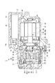
- the electric compressor 1 includes a housing 10 forming an outer shell thereof, a compression mechanism 20 including a fixed scroll 21 and a orbiting scroll 25 for compressing a refrigerant used in a vehicle air conditioner, and a main shaft 30 for driving the orbiting scroll 25 , And an electric motor 40 for driving the main shaft 30.
- the housing 10 has a three-piece structure including a compressor housing 11, an inner housing 14, and a motor housing 16. Each member is manufactured, for example, by die casting an aluminum alloy.
- the fixed scroll 21 and the orbiting scroll 25 are manufactured by forging.
- the compressor housing 11 is a member formed in a bottomed cylindrical shape, and the fixed scroll 21 is fixed to the bottom surface. Between the compressor housing 11 and the fixed scroll 21 is formed a discharge chamber 12 into which the refrigerant compressed by the fixed scroll 21 and the orbiting scroll 25 flows.
- an oil reservoir 13 is provided between the compressor housing 11 and the fixed scroll 21.
- the oil reservoir 13 is an air gap formed between the compressor housing 11 and the fixed scroll 21, and the lubricating oil contained in the refrigerant discharged from the discharge port 28 is temporarily stored.
- the lubricating oil contained in the refrigerant is separated by an oil separator (not shown) and then transferred to the oil reservoir 13.
- the lubricating oil stored in the oil reservoir 13 returns to the upstream side of the electric compressor 1 through the oil return flow path 24 formed in the fixed scroll 21 and is contained in the refrigerant.
- the refrigerant containing the lubricating oil is compressed by the compression mechanism 20 and then discharged to the discharge chamber 12.
- the lubricating oil circulates the inside of the motor-driven compressor 1 and lubricates sliding parts such as the main bearing 35, the sub bearing 34, the fixed scroll 21 and the orbiting scroll 25.
- the upstream and the downstream follow the flow direction of the refrigerant.
- the inner housing 14 is disposed so as to be sandwiched between the compressor housing 11 and the motor housing 16.
- the inner housing 14 holds a main bearing 35 that rotatably supports the main shaft 30.
- An oil return passage 15 is formed in the inner housing 14.
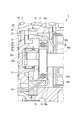
- One end of the oil return flow passage 15 communicates with the oil return flow passage 24 provided in the fixed scroll 21, and the other end opens in the holding surface 14 a facing the outer peripheral surface of the outer ring 35 b (FIG. 2) of the main bearing 35. Therefore, the motor-driven compressor 1 is provided with a lubricant oil return flow path consisting of the oil return flow path 24 and the oil return flow path 15 between the oil reservoir 13 and the main bearing 35 (outer ring 35 b).
- the motor housing 16 has the stator 43 of the motor 40 fixed therein.
- the motor housing 16 is provided with a suction port (not shown) into which the refrigerant flows from the outside, and an inverter storage box 17.
- the inverter storage box 17 has an opening whose top is closed by a lid 18, and an inverter device 45 for controlling the driving of the motor 40 is housed in the closed space.
- the fixed scroll 21 and the orbiting scroll 25 forming the compression mechanism 20 form a closed compression chamber C to compress the refrigerant, as shown in FIG.
- the fixed scroll 21 includes a fixed end plate 22 and a spiral fixed wrap 23 extending from the fixed end plate 22 toward the orbiting scroll 25.
- An oil return passage 24 is formed in the fixed end plate 22.
- One end of the oil return flow passage 24 communicates with the oil reservoir 13, and the other end communicates with the oil return flow passage 15 formed in the inner housing 14.
- a discharge port 28 is provided at the center of the fixed end plate 22, and the refrigerant compressed in the compression chamber C is discharged to the discharge chamber 12 via the discharge port 28.
- the orbiting scroll 25 includes an orbiting end plate 26 and a spiral orbiting wrap 27 extending from the orbiting end plate 26 toward the fixed scroll 21.
- the orbiting scroll 25 is rotatably supported by the main shaft 30 and the anti-rotation part (oldam ring) 39.
- the pivoting end plate 26 is provided with a cylindrical boss 29 extending toward the main shaft 30 on the surface opposite to the main shaft 30.
- a needle bearing 38 rotatably supporting a bush 36 to which a revolution driving force by the main shaft 30 is transmitted is disposed on the boss 29.
- the main shaft 30 is a cylindrical member disposed from the motor 40 to the orbiting scroll 25, and is rotatably supported by the compressor housing 11 via the sub bearing 34 and the main bearing 35.
- the main shaft 30 has a cylindrical crankshaft 30a fixed to the rotor 41, a disc-like fitting portion 30b having a diameter larger than that of the crankshaft 30a, and a position offset from the central axis of the crankshaft 30a to the central axis And a crank pin 30c extending along the same.
- the crankshaft 30 a has a central axis substantially horizontal, and transmits the rotational driving force generated by the rotor 41 and the stator 43 to the orbiting scroll 25.
- the fitting portion 30b is a portion to be fitted to and supported by the main bearing 35, the crankshaft 30a is provided on one surface side in the axial direction, and the crankpin 30c is provided on the other surface side.
- the fitting portion 30 b is supported by the main bearing 35 by being press-fitted into the inner ring 35 a (FIG. 2) of the main bearing 35.
- the crank pin 30 c transmits the rotational drive force transmitted to the crankshaft 30 a to the orbiting scroll 25 to rotationally drive the orbiting scroll 25.
- the crank pin 30c extends from the position eccentric from the center of the fitting portion 30b toward the orbiting scroll 25 along the central axis of the crankshaft 30a.
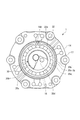
- the main bearing 35 is a radial bearing which comprises an inner ring 35a, an outer ring 35b, and a plurality of spherical rolling elements 35c provided between the inner ring 35a and the outer ring 35b.
- the inner ring 35 a supports the fitting portion 30 b of the main shaft 30 and rotates in synchronization with the rotation of the main shaft 30.
- the main bearing 35 is supported on the inner housing 14 by gap fitting (JIS B 0401), and the fit between the main bearing 35 and the inner housing 14 is one of the features of the present embodiment.
- a bush 36 is disposed between the crank pin 30 c and the boss 29.
- the bush 36 is a substantially cylindrical member that transmits a revolution driving force to the orbiting scroll 25.
- crank hole 36a is formed in which the crankpin 30c is inserted.
- a needle bearing 38 rotatably supporting the bush 36 is provided between the bush 36 and the boss 29.
- a counterweight 37 is provided on the outer periphery of the bush 36.
- the counterweight 37 is a member for adjusting the pressing force of the orbiting scroll 25 on the fixed scroll 21 and for balancing.
- a limit pin which is a member for adjusting the revolution radius of the orbiting scroll 25 and a limit hole into which the limit pin is inserted.
- the electric motor 40 is rotationally driven by a frequency-controlled alternating current, and is a drive source that drives the orbiting scroll 25 to revolve. As shown in FIG. 1, the electric motor 40 includes a rotor 41 that revolves the orbiting scroll 25 via the main shaft 30, and a stator 43. The alternating current controlled by the inverter device 45 is supplied to the stator 43.
- the rotor 41 generates a rotational driving force by an AC magnetic field formed by the stator 43, and is formed of a cylindrically formed permanent magnet.
- the crankshaft 30 a of the main shaft 30 is fixed to the rotor 41.
- the stator 43 forms an alternating magnetic field based on the alternating current supplied from the inverter device 45 to rotate the rotor 41.
- the stator 43 is fixed to the inner peripheral surface of the motor housing 16 by a method such as shrink fitting.
- the inverter device 45 controls an alternating current supplied to the stator 43, and is disposed in the inverter accommodation box 17.
- the inverter device 45 includes a plurality of substrates provided with electronic elements such as capacitors (capacitors) and power transistors.
- the rotational driving force is transmitted to the crankshaft 30a and the fitting portion 30b of the main shaft 30, and the crank pin 30c is rotationally driven by the rotation of the fitting portion 30b.
- the pivoting motion of the crank pin 30 c is transmitted to the pivoting scroll 25 via the bush 36 and the boss 29.
- the orbiting scroll 25 is driven to revolve while its rotation movement is restricted by the rotation prevention unit 39.
- the compression chamber C formed between the orbiting scroll 25 and the fixed scroll 21 takes in and compresses the refrigerant flowing from the motor housing 16 into the interior of the electric compressor 1. Specifically, the compression chamber C takes in the refrigerant at the outer peripheral end of the fixed scroll 21 and the orbiting scroll 25. Then, as the orbiting scroll 25 revolves, the compression chamber C decreases in volume as it moves from the outer peripheral end toward the center along the fixed wrap 23 and the orbiting wrap 27, and the taken-in refrigerant is compressed. The refrigerant compressed into the compression chamber C is discharged to the discharge chamber 12 via the discharge port 28 of the fixed scroll 21 and discharged from the inside of the discharge chamber 12 to the outside of the housing 10 (compressor housing 11).
- the lubricating oil separated from the refrigerant flowing into the discharge chamber 12 flows into the oil reservoir 13.
- the inside of the housing 10 relatively has a low pressure atmosphere on the upstream side and a high pressure atmosphere on the downstream side with the compression mechanism 20 as a boundary.
- the return passage of the lubricating oil which is provided between the oil reservoir 13 and the main bearing 35 (the outer ring 35b) and which comprises the oil return passage 24 and the oil return passage 15, has one end on the main bearing 35 side in a low pressure atmosphere. It will connect and the end by the side of oil reservoir 13 will connect with high pressure atmosphere. Therefore, the lubricating oil stored in the oil reservoir 13 is discharged from the holding surface 14 a of the inner housing 14 sequentially through the oil return flow path 24 and the oil return flow path 15 due to the differential pressure between the high pressure atmosphere and the low pressure atmosphere. .
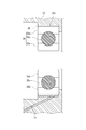
- the discharged lubricating oil penetrates around the outer ring 35b of the main bearing 35 held by gap fitting inside the holding surface 14a, and as shown in FIG. 3, between the main bearing 35 and the holding surface 14a An oil film OF is formed.
- the oil film OF functions as a damper with respect to the main bearing 35. Therefore, it can suppress that the vibration which arose in the electric compressor 1 is transmitted to the housing 10 via the main bearing 35.
- the lubricating oil forming the oil film OF is continuously supplied while the motor-driven compressor 1 is driven, the damper effect by the oil film formation can be stably obtained.
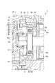
- the electric compressor 1 can be provided with a snap ring 32 for retaining the main bearing 35 as shown in FIGS. 4 and 5. If the temperature of the electric compressor 1 rises during operation, the housing 10 made of aluminum alloy has a larger amount of thermal expansion than the main bearing 35 made of iron-based alloy, so that the main bearing 35 is prevented from coming off in the axial direction For this purpose, a snap ring 32 is provided.
- the snap ring 32 is a ring-shaped metal member having a split opening 32 a partially cut in the radial direction.
- the outer edge side of the snap ring 32 is inserted into a holding groove 14c formed continuously in the circumferential direction of the inner peripheral surface of the inner housing 14, and is fixed to the inner housing 14 by appropriate fastening means.
- the snap ring 32 is disposed so as to be in contact with one axial end face of the main bearing 35, thereby serving to prevent the main bearing 35 from coming off.
- the snap ring 32 is disposed such that the slit 32a is positioned at the top of the height direction. Therefore, in the gap between the holding surface 14a of the inner housing 14 and the outer ring 35b of the main bearing 35, the uppermost region where the split port 32a is provided is released to the outside, and lower than this region The area is sealed by a snap ring 32. In addition, a discharge path 14d is formed in the holding surface 14a of the inner housing 14 corresponding to the uppermost position.
- the lubricating oil forming the oil film formed between the holding surface 14a and the outer ring 35b is pushed up to the uppermost area under the influence of the above-mentioned differential pressure, but this area is released to the outside, and the discharge passage 14d Because of this, the pushed-up lubricating oil is easily discharged to the outside.
- the discharged lubricating oil is dropped toward sliding members such as a bushing 36 and a needle bearing 38 which are disposed below the discharged position.
- the lubricant oil can be stably supplied to the drive bush by selecting the position of the split opening 32a of the snap ring 32 that prevents the main bearing 35 from coming off, so the reliability of the electric compressor 1 can be improved. Can be secured.
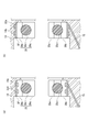
- the electric compressor 1 can be provided with oil grooves 35d, 35d connected in the circumferential direction on the outer peripheral surface of the outer ring 35b of the main bearing 35.
- the oil grooves 35d, 35d By providing the oil grooves 35d, 35d, the amount of lubricating oil present as an oil film between the holding surface 14a and the outer ring 35b can be increased, so that the damper effect by the oil film formation can be improved.
- An oil groove for increasing the amount of lubricating oil can also be provided on the holding surface 14a of the inner housing 14, as shown in FIG. 6 (b).
- Forming the oil grooves 14b, 14b is easier in processing than forming the oil grooves 35d, 35d on the outer peripheral surface of the outer ring 35b. That is, since the bearing is usually circulated such that the outer peripheral surface of the outer ring is flat, it is necessary to form the oil grooves 35d, 35d by cutting again.
- the oil grooves 14b and 14b are provided in the inner housing 14, it is sufficient if the oil grooves 14b and 14b are formed at the time of casting simultaneously with the other parts. It is sufficient to do slight processing to the extent that the surfaces of 14b and 14b are finished.
- Oil grooves for increasing the amount of lubricating oil can be formed on both the outer ring 35 b of the main bearing 35 and the holding surface 14 a of the inner housing 14. Further, although the oil grooves are formed in two rows (oil grooves 35d, 35d and oil grooves 14b, 14b) here, this is merely an example and may be one row or three rows.
- the housing 10 of the electric compressor 1 has a three-piece structure
- the present invention can also be applied to an electric compressor having a two-piece housing.
- the drive source of the compression mechanism 20 is the motor 40 in the above embodiment, the drive source is not limited, and the present invention can be applied to, for example, a compressor using an automobile engine as a drive source.
Landscapes
- Engineering & Computer Science (AREA)
- Mechanical Engineering (AREA)
- General Engineering & Computer Science (AREA)
- Applications Or Details Of Rotary Compressors (AREA)
- Rotary Pumps (AREA)
Priority Applications (3)
| Application Number | Priority Date | Filing Date | Title |
|---|---|---|---|
| DE112014003869.5T DE112014003869B4 (de) | 2013-08-23 | 2014-08-11 | Spiralverdichter |
| US14/903,889 US9739279B2 (en) | 2013-08-23 | 2014-08-11 | Lubrication reservoir and recirculation arrangement for scroll compressor bearing |
| CN201480042755.6A CN105452664B (zh) | 2013-08-23 | 2014-08-11 | 涡旋式压缩机 |
Applications Claiming Priority (2)
| Application Number | Priority Date | Filing Date | Title |
|---|---|---|---|
| JP2013172972A JP6190663B2 (ja) | 2013-08-23 | 2013-08-23 | スクロール圧縮機 |
| JP2013-172972 | 2013-08-23 |
Publications (1)
| Publication Number | Publication Date |
|---|---|
| WO2015025502A1 true WO2015025502A1 (ja) | 2015-02-26 |
Family
ID=52483297
Family Applications (1)
| Application Number | Title | Priority Date | Filing Date |
|---|---|---|---|
| PCT/JP2014/004170 Ceased WO2015025502A1 (ja) | 2013-08-23 | 2014-08-11 | スクロール圧縮機 |
Country Status (5)
| Country | Link |
|---|---|
| US (1) | US9739279B2 (enExample) |
| JP (1) | JP6190663B2 (enExample) |
| CN (1) | CN105452664B (enExample) |
| DE (1) | DE112014003869B4 (enExample) |
| WO (1) | WO2015025502A1 (enExample) |
Cited By (1)
| Publication number | Priority date | Publication date | Assignee | Title |
|---|---|---|---|---|
| WO2023240969A1 (zh) * | 2022-06-16 | 2023-12-21 | 珠海格力电器股份有限公司 | 压缩机的回油结构、压缩机和空调器 |
Families Citing this family (6)
| Publication number | Priority date | Publication date | Assignee | Title |
|---|---|---|---|---|
| KR102202419B1 (ko) * | 2015-04-17 | 2021-01-13 | 한온시스템 주식회사 | 전동 압축기 |
| CN107630814B (zh) * | 2017-09-04 | 2023-10-03 | 珠海格力电器股份有限公司 | 涡旋压缩机、节流结构及空调器 |
| DE102018204278B4 (de) | 2018-03-20 | 2020-02-06 | Volkswagen Aktiengesellschaft | Spiralverdichter und Verfahren zu dessen Montage |
| JP6888157B1 (ja) * | 2020-07-17 | 2021-06-16 | 日立ジョンソンコントロールズ空調株式会社 | スクロール圧縮機、及び冷凍サイクル装置 |
| CN114320902A (zh) * | 2020-09-30 | 2022-04-12 | 安徽威灵汽车部件有限公司 | 涡旋压缩机、空调设备及车辆 |
| KR20230142070A (ko) * | 2022-03-31 | 2023-10-11 | 한온시스템 주식회사 | 전동 압축기 |
Citations (3)
| Publication number | Priority date | Publication date | Assignee | Title |
|---|---|---|---|---|
| JPS5929793A (ja) * | 1982-08-11 | 1984-02-17 | Hitachi Ltd | 回転圧縮機 |
| JP2008208717A (ja) * | 2007-02-23 | 2008-09-11 | Mitsubishi Heavy Ind Ltd | スクロール圧縮機 |
| JP2012188989A (ja) * | 2011-03-10 | 2012-10-04 | Yanmar Co Ltd | 外周駆動型スクロール流体機械 |
Family Cites Families (13)
| Publication number | Priority date | Publication date | Assignee | Title |
|---|---|---|---|---|
| KR910001824B1 (ko) * | 1987-08-10 | 1991-03-26 | 가부시기가이샤 히다찌세이사꾸쇼 | 스크롤 압축기의 급유장치 |
| JP2639136B2 (ja) | 1989-11-02 | 1997-08-06 | 松下電器産業株式会社 | スクロール圧縮機 |
| JP2002285982A (ja) | 2001-03-26 | 2002-10-03 | Toyota Industries Corp | スクロール型圧縮機およびスクロール型圧縮機の潤滑油供給方法 |
| US7101160B2 (en) * | 2003-03-31 | 2006-09-05 | Kabushiki Kaisha Toyota Jidoshokki | Electric compressor |
| JP4273807B2 (ja) * | 2003-03-31 | 2009-06-03 | 株式会社豊田自動織機 | 電動圧縮機 |
| JP4329528B2 (ja) | 2003-12-19 | 2009-09-09 | 株式会社豊田自動織機 | スクロールコンプレッサ |
| JP4881666B2 (ja) * | 2006-07-07 | 2012-02-22 | 日立アプライアンス株式会社 | 横型スクロール圧縮機 |
| DE102008013784B4 (de) * | 2007-03-15 | 2017-03-23 | Denso Corporation | Kompressor |
| JP4992822B2 (ja) * | 2008-05-16 | 2012-08-08 | 株式会社豊田自動織機 | スクロール型圧縮機 |
| JP5315933B2 (ja) * | 2008-06-05 | 2013-10-16 | 株式会社豊田自動織機 | 電動スクロール型圧縮機 |
| KR101042393B1 (ko) * | 2008-07-02 | 2011-06-17 | 주식회사 두원전자 | 오일 분리기 |
| JP5637151B2 (ja) | 2012-01-20 | 2014-12-10 | 株式会社豊田自動織機 | 差圧弁及び差圧弁を備える電動圧縮機 |
| JP5929793B2 (ja) * | 2013-03-18 | 2016-06-08 | 富士ゼロックス株式会社 | 画像形成装置 |
-
2013
- 2013-08-23 JP JP2013172972A patent/JP6190663B2/ja active Active
-
2014
- 2014-08-11 CN CN201480042755.6A patent/CN105452664B/zh active Active
- 2014-08-11 US US14/903,889 patent/US9739279B2/en not_active Expired - Fee Related
- 2014-08-11 DE DE112014003869.5T patent/DE112014003869B4/de active Active
- 2014-08-11 WO PCT/JP2014/004170 patent/WO2015025502A1/ja not_active Ceased
Patent Citations (3)
| Publication number | Priority date | Publication date | Assignee | Title |
|---|---|---|---|---|
| JPS5929793A (ja) * | 1982-08-11 | 1984-02-17 | Hitachi Ltd | 回転圧縮機 |
| JP2008208717A (ja) * | 2007-02-23 | 2008-09-11 | Mitsubishi Heavy Ind Ltd | スクロール圧縮機 |
| JP2012188989A (ja) * | 2011-03-10 | 2012-10-04 | Yanmar Co Ltd | 外周駆動型スクロール流体機械 |
Cited By (1)
| Publication number | Priority date | Publication date | Assignee | Title |
|---|---|---|---|---|
| WO2023240969A1 (zh) * | 2022-06-16 | 2023-12-21 | 珠海格力电器股份有限公司 | 压缩机的回油结构、压缩机和空调器 |
Also Published As
| Publication number | Publication date |
|---|---|
| DE112014003869T5 (de) | 2016-05-25 |
| US9739279B2 (en) | 2017-08-22 |
| CN105452664A (zh) | 2016-03-30 |
| DE112014003869B4 (de) | 2019-09-19 |
| US20160160861A1 (en) | 2016-06-09 |
| JP2015040537A (ja) | 2015-03-02 |
| JP6190663B2 (ja) | 2017-08-30 |
| CN105452664B (zh) | 2017-03-15 |
Similar Documents
| Publication | Publication Date | Title |
|---|---|---|
| WO2015025502A1 (ja) | スクロール圧縮機 | |
| JP4143827B2 (ja) | スクロール圧縮機 | |
| JP2017078361A (ja) | スクロール流体機械 | |
| JP6762253B2 (ja) | 回転式圧縮機及び冷凍サイクル装置 | |
| JP6102866B2 (ja) | 圧縮機 | |
| JP2018193858A (ja) | 電動過給機 | |
| WO2016125228A1 (ja) | 圧縮機 | |
| EP3159545B1 (en) | Scroll fluid machine | |
| JP2015158156A (ja) | スクロール型圧縮機 | |
| JP2000337256A (ja) | 流体機械 | |
| JP6808044B2 (ja) | スクロール圧縮機 | |
| JP2011179374A (ja) | スクロール型圧縮機 | |
| JP4743377B2 (ja) | スクロール圧縮機 | |
| JP4681322B2 (ja) | スクロール圧縮機 | |
| JP2005214173A (ja) | 密閉形スクロール圧縮機 | |
| JP2014136985A (ja) | スクロール型圧縮機 | |
| JP2006090180A (ja) | 密閉型圧縮機 | |
| JP3356460B2 (ja) | 密閉型圧縮機 | |
| JP5836845B2 (ja) | スクロール圧縮機 | |
| KR20140095702A (ko) | 스크롤 압축기 | |
| WO2022137923A1 (ja) | スクロール型圧縮機 | |
| JP5463340B2 (ja) | スクロール圧縮機 | |
| JP2013064341A (ja) | スクロール圧縮機 | |
| JP7638145B2 (ja) | スクロール圧縮機 | |
| JP2020112142A (ja) | スクロール型流体機械 |
Legal Events
| Date | Code | Title | Description |
|---|---|---|---|
| WWE | Wipo information: entry into national phase |
Ref document number: 201480042755.6 Country of ref document: CN |
|
| 121 | Ep: the epo has been informed by wipo that ep was designated in this application |
Ref document number: 14837731 Country of ref document: EP Kind code of ref document: A1 |
|
| WWE | Wipo information: entry into national phase |
Ref document number: 14903889 Country of ref document: US |
|
| WWE | Wipo information: entry into national phase |
Ref document number: 1120140038695 Country of ref document: DE Ref document number: 112014003869 Country of ref document: DE |
|
| 122 | Ep: pct application non-entry in european phase |
Ref document number: 14837731 Country of ref document: EP Kind code of ref document: A1 |