WO2015019948A1 - ブラシレスモータ - Google Patents
ブラシレスモータ Download PDFInfo
- Publication number
- WO2015019948A1 WO2015019948A1 PCT/JP2014/070311 JP2014070311W WO2015019948A1 WO 2015019948 A1 WO2015019948 A1 WO 2015019948A1 JP 2014070311 W JP2014070311 W JP 2014070311W WO 2015019948 A1 WO2015019948 A1 WO 2015019948A1
- Authority
- WO
- WIPO (PCT)
- Prior art keywords
- rotor core
- core
- magnet
- rotor
- brushless motor
- Prior art date
- Legal status (The legal status is an assumption and is not a legal conclusion. Google has not performed a legal analysis and makes no representation as to the accuracy of the status listed.)
- Ceased
Links
Images


Classifications
-
- H—ELECTRICITY
- H02—GENERATION; CONVERSION OR DISTRIBUTION OF ELECTRIC POWER
- H02K—DYNAMO-ELECTRIC MACHINES
- H02K21/00—Synchronous motors having permanent magnets; Synchronous generators having permanent magnets
- H02K21/12—Synchronous motors having permanent magnets; Synchronous generators having permanent magnets with stationary armatures and rotating magnets
- H02K21/14—Synchronous motors having permanent magnets; Synchronous generators having permanent magnets with stationary armatures and rotating magnets with magnets rotating within the armatures
- H02K21/16—Synchronous motors having permanent magnets; Synchronous generators having permanent magnets with stationary armatures and rotating magnets with magnets rotating within the armatures having annular armature cores with salient poles
-
- H—ELECTRICITY
- H02—GENERATION; CONVERSION OR DISTRIBUTION OF ELECTRIC POWER
- H02K—DYNAMO-ELECTRIC MACHINES
- H02K29/00—Motors or generators having non-mechanical commutating devices, e.g. discharge tubes or semiconductor devices
- H02K29/03—Motors or generators having non-mechanical commutating devices, e.g. discharge tubes or semiconductor devices with a magnetic circuit specially adapted for avoiding torque ripples or self-starting problems
-
- H—ELECTRICITY
- H02—GENERATION; CONVERSION OR DISTRIBUTION OF ELECTRIC POWER
- H02K—DYNAMO-ELECTRIC MACHINES
- H02K1/00—Details of the magnetic circuit
- H02K1/06—Details of the magnetic circuit characterised by the shape, form or construction
- H02K1/22—Rotating parts of the magnetic circuit
- H02K1/24—Rotor cores with salient poles ; Variable reluctance rotors
-
- H—ELECTRICITY
- H02—GENERATION; CONVERSION OR DISTRIBUTION OF ELECTRIC POWER
- H02K—DYNAMO-ELECTRIC MACHINES
- H02K1/00—Details of the magnetic circuit
- H02K1/06—Details of the magnetic circuit characterised by the shape, form or construction
- H02K1/22—Rotating parts of the magnetic circuit
- H02K1/27—Rotor cores with permanent magnets
- H02K1/2706—Inner rotors
- H02K1/272—Inner rotors the magnetisation axis of the magnets being perpendicular to the rotor axis
- H02K1/274—Inner rotors the magnetisation axis of the magnets being perpendicular to the rotor axis the rotor consisting of two or more circumferentially positioned magnets
- H02K1/2753—Inner rotors the magnetisation axis of the magnets being perpendicular to the rotor axis the rotor consisting of two or more circumferentially positioned magnets the rotor consisting of magnets or groups of magnets arranged with alternating polarity
- H02K1/276—Magnets embedded in the magnetic core, e.g. interior permanent magnets [IPM]
-
- H—ELECTRICITY
- H02—GENERATION; CONVERSION OR DISTRIBUTION OF ELECTRIC POWER
- H02K—DYNAMO-ELECTRIC MACHINES
- H02K1/00—Details of the magnetic circuit
- H02K1/06—Details of the magnetic circuit characterised by the shape, form or construction
- H02K1/12—Stationary parts of the magnetic circuit
- H02K1/16—Stator cores with slots for windings
-
- H—ELECTRICITY
- H02—GENERATION; CONVERSION OR DISTRIBUTION OF ELECTRIC POWER
- H02K—DYNAMO-ELECTRIC MACHINES
- H02K2213/00—Specific aspects, not otherwise provided for and not covered by codes H02K2201/00 - H02K2211/00
- H02K2213/03—Machines characterised by numerical values, ranges, mathematical expressions or similar information
Definitions
- the present invention relates to a cogging reduction technique for a brushless motor, and more particularly to reduction of cogging in a magnet embedded motor (IPM motor: Interior ⁇ ⁇ ⁇ Permanent Magnet Motor).
- IPM motor Interior ⁇ ⁇ ⁇ Permanent Magnet Motor
- IPM motor magnet-embedded brushless motor
- a magnet is embedded in the rotor and the rotor is rotated by both the magnet torque generated by the magnetic force of the magnet and the reluctance torque generated by the magnetization of the rotor
- IPM motor can utilize reluctance torque in addition to magnet torque, it becomes a motor with high efficiency and high torque.
- IPM motors are also increasingly used in hybrid cars and air conditioners.
- FIG. 7 is an explanatory diagram showing the configuration of the IPM motor.
- the IPM motor 51 is also provided with a stator 52 on the outer side and a rotor 53 on the inner side, similarly to a normal electric motor.
- the stator 52 includes a stator core 54 in which a large number of thin steel plate materials are laminated, and a coil 55 wound around a tooth (not shown) of the stator core 54.
- the rotor 53 has a rotor core 57 fixed to the shaft 56 and a magnet 58 embedded in the rotor core 57.
- the rotor core outer peripheral portion 57a is located outside the magnet 58 and also functions as a pseudo magnetic pole.
- the IPM motor 51 rotates the rotor 53 using both magnet torque and reluctance torque.
- a rotor core outer peripheral portion 57 a made of a magnetic material is interposed between the magnet 58 and the stator 52.
- the magnetic flux is likely to concentrate due to the three-dimensional magnetic flux leakage from the magnet end face (P portion in FIG. 7), and the magnetic flux density varies in the axial direction.
- a magnetic flux concentrating portion (Q portion in FIG. 7) is generated at the end portions thereof, so that the variation in the magnetic flux density in the axial direction is further increased. As a result, cogging during rotor rotation increases.
- the brushless motor of the present invention includes a stator having a stator core formed of a magnetic material, a rotor core that is rotatably disposed inside the stator and formed of a magnetic material, and a plurality of stator cores fixed in the rotor core.
- a rotor including a magnet, and the rotor core includes a core body fixed to a rotor shaft, and the magnet is provided at equal intervals along a circumferential direction of the core body.
- a plurality of magnet mounting portions to be accommodated wherein the axial length Lr of the rotor core is longer than the axial length Lm of the magnet (Lr> Lm), and the axial length Ls of the stator core is The rotor core is longer than the axial length Lr (Ls> Lr).
- first overhang portions are provided that extend along the axial direction from the axial end portion of the magnet without facing the magnet, and at both end portions of the stator core, You may provide the 2nd overhang part which protruded along the axial direction from the axial direction edge part of the said rotor core, without facing the said rotor core.
- a 1st overhang part suppresses the magnetic flux which flows in into a rotor core from the axial direction end surface of a magnet, and equalizes the magnetic flux density in a rotor core.
- the second overhang portion suppresses the magnetic flux flowing into the stator core from the axial end surface of the rotor core, and makes the magnetic flux density uniform in the stator core.
- the axial lengths X1 and X2 of the first and second overhang portions may be set to be greater than 0 to 1.0 mm or less, and the axial lengths of the first and second overhang portions may be set in the axial direction.
- the rotor core may be provided with a plurality of salient pole portions formed on the outer peripheral side of the magnet mounting portion and disposed on the outer peripheral portion of the rotor.
- a rotor core having a core body fixed to the rotor shaft and a magnet mounting portion provided on the core body is used.
- the axial length Lr of the rotor core is set longer than the axial length Lm of the magnet (Lr> Lm), and the axial length Ls of the stator core is set longer than the axial length Lr of the rotor core (Ls> Lr).
- FIG. 2 is a cross-sectional view taken along line AA in FIG. It is explanatory drawing which shows the relationship of each axial direction length of a magnet, a rotor core, and a stator core. It is explanatory drawing which shows the relationship between the amount X1 of rotor core overhangs with respect to a magnet, cogging torque, and output torque. It is explanatory drawing which shows the relationship between the overhanging amount X2 of the stator core with respect to a rotor core, a cogging torque, and an output torque. It is explanatory drawing which shows the example of the other IPM motor which can apply this invention. It is explanatory drawing which shows the structure of an IPM motor.
- FIG. 1 is a cross-sectional view of a brushless motor 1 (hereinafter abbreviated as motor 1) according to an embodiment of the present invention.
- FIG. 2 is a sectional view taken along line AA in FIG.
- the motor 1 is an IPM type brushless motor that rotates a rotor by a reluctance torque based on an inductance difference and a magnet torque generated by a magnetic force of a magnet. As shown in FIG.
- the motor 1 is an inner rotor type brushless motor in which a stator (stator) 2 is arranged on the outside and a rotor (rotor) 3 is arranged on the inside.
- the motor 1 is a flat IPM motor that satisfies D / L> 1, and is used as a drive source of the electric power steering apparatus.
- the stator 2 is fixed inside a bottomed cylindrical motor case 4 (hereinafter abbreviated as case 4).
- the stator 2 includes a stator core 5, a stator coil 6 (hereinafter abbreviated as a coil 6), and a bus bar unit (terminal unit) 7.
- the coil 6 is wound around a plurality of teeth 9 of the stator core 5 via an insulator 11.
- Bus bar unit 7 is attached to stator core 5 and electrically connected to coil 6.
- nine tooth portions 9 are provided.
- the coil 6 is disposed in nine slots between the adjacent tooth portions 9.
- the case 4 is formed in a bottomed cylindrical shape with iron or the like.
- An aluminum die cast bracket 8 is attached to the opening of the case 4 by a fixing screw (not shown).
- the stator core 5 has a plurality of teeth 9 projecting radially inward.
- a slot 10 is formed between adjacent teeth 9.
- a coil 6 is accommodated in the slot 10.
- a synthetic resin insulator 11 is attached to the stator core 5.
- a coil 6 is wound around the outside of the insulator 11.
- a bus bar unit 7 positioned by an insulator 11 is attached to one end side in the axial direction of the stator core 5.
- the bus bar unit 7 includes a synthetic resin main body portion and a copper bus bar insert-molded in the main body portion.
- connection terminal 12 project in the radial direction.
- the connection terminal 12 is welded to the end portion 6 a of each coil 6 drawn from the stator core 5.
- the number of bus bars corresponding to the number of phases of the motor 1 here, three for U phase, V phase, W phase and one for connecting each phase
- Each coil 6 is electrically connected to a connection terminal 12 corresponding to the phase.
- the stator core 5 is fixed in the case 4 by fixing means such as press fitting or adhesion.
- the rotor 3 is inserted into the stator 2 so as to be concentric with the stator 2.
- the rotor 3 has a rotor shaft 13.
- the rotor shaft 13 is rotatably supported by bearings 14a and 14b.
- the bearing 14 a is fixed to the bottom center of the case 4.
- the bearing 14 b is fixed to the center portion of the bracket 8.
- a cylindrical rotor core 15 and a rotor (resolver rotor) 22 of a resolver 21 serving as a rotation angle detection unit are attached to the rotor shaft 13.
- a stator (resolver stator) 23 of the resolver 21 is accommodated in a resolver holder 24a.
- the resolver holder 24a is fixed to the inner side of the bracket 8 by a mounting screw 25 via a resolver bracket 24b made of synthetic resin.
- a plurality of magnet mounting holes (magnet mounting portions) 31 are provided on the outer peripheral portion of the rotor core 15 along the circumferential direction.
- the magnet mounting hole 31 penetrates the rotor core 15 in the axial direction.
- the magnets 16 are accommodated and fixed in the magnet mounting holes 31 respectively.
- a salient pole portion 32 is formed on the outer peripheral side of each magnet 16.
- Six magnets 16 are arranged along the circumferential direction, and the motor 1 has a 6-pole 9-slot configuration.
- a gap 33 is formed in the magnet mounting hole 31.
- the gap 33 is formed on both sides of the magnet 16 in the circumferential direction and functions as a flux barrier that hardly allows magnetic flux to pass. Between the adjacent salient pole portions 32, a bridge portion 34 for connecting the core body 15a and the salient pole portion 32 is provided.
- stator core plate 17 of the stator core 5 and the rotor core plate 18 of the rotor core 15 are both formed by laminating electromagnetic steel plates having a thickness of 0.5 mm. Accordingly, both plates 17 and 18 can be press-molded from the same blank material, and various physical properties such as magnetic flux characteristics are substantially equal.
- the axial length of the rotor core 15 is longer than the axial length of the magnet 16 and the stator core is longer than the axial length of the rotor core 15 in order to suppress the wraparound of the magnetic flux from the axial end face side.
- the axial length of 5 is set longer (magnet length ⁇ rotor core length ⁇ stator core length).
- the axial direction of the rotor core 15 means that at least the axial length of the salient pole portion 32 located outside the magnet 16 is longer than that of the magnet 16. That is, in the rotor core 15, the axial length of the core body 15 a located on the inner peripheral side with respect to the magnet 16 is not necessarily longer than that of the magnet 16. Therefore, for example, in order to reduce the weight and reduce the inertia, the core body 15a inside the magnet 16 can be shortened by cutting or the like.
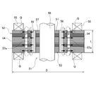
- FIG. 3 is an explanatory diagram showing the relationship between the axial lengths of the magnet 16, the rotor core 15, and the stator core 5 in the motor 1.
- the dimensional relationship is exaggerated to clearly show the features of the present invention.
- the axial length Lr of the rotor core 15 is longer than the axial length Lm of the magnet 16 (Lr> Lm).
- the axial length Ls of the stator core 5 is longer than the axial length Lr of the rotor core 15 (Ls> Lr).
- a first overhang portion 41 (overhang amount X1) that does not face the magnet 16 is formed at both ends of the rotor core 15.
- a second overhang portion 42 (overhang amount X2) that does not face the rotor core 15 is also formed at both ends of the stator core 5.
- the overhang portions 41 and 42 are equally distributed at the end portions in the axial direction, not at one end portion in the axial direction of the rotor core 15 or the stator core 5.
- the difference between Lr and Lm is set to be larger than the minimum value of the difference between the two considering the dimensional tolerances of Lr and Lm.
- the difference between Ls and Lr is also set to be larger than the minimum value of the difference between the two considering the dimensional tolerances of Ls and Lr. Therefore, even if the axial length of each component varies and the tolerances are accumulated, the overhang portions 41 and 42 are secured.
- the overhang amounts X1 and X2 in the overhang portions 41 and 42 can be adjusted as appropriate by changing the plate thickness and the number of stacked layers of the thin plate materials constituting the stator core 5 and the rotor core 15.
- the magnetic flux from the rotor core 15 flows into the inner surface side of the stator core 5.
- the magnetic flux from the rotor core 15 also flows into the overhang portion 42 that is the inner surface of the stator core 5 at the axial end portion of the salient pole 32.
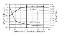
- FIG. 4 is an explanatory diagram showing the relationship between the overhang amount X1 (one-side overhang amount), the cogging torque, and the output torque in the motor 1.
- the overhang portion 41 when the overhang portion 41 is provided, the cogging decreases rapidly. The cogging is remarkably reduced until the overhang amount X1 is 0.5 to 1 mm (the plate thickness tr of the rotor core plate 18 to about twice the plate thickness tr).
- the overhang amount X1 exceeds 1 mm, the cogging reduction amount is reduced, and thereafter, the state becomes almost flat.
- the output torque gradually increases until the overhang amount X1 is about 1 mm, and then becomes substantially level. If the overhang amount X1 is increased, the motor becomes larger. Therefore, from the viewpoint of reducing the size and weight of the motor, X1 is preferably as small as possible. Therefore, considering the effect of the overhang portion 41, the overhang amount X1 is preferably about 1 mm as can be seen from FIG.
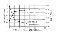
- FIG. 5 is an explanatory diagram showing the relationship between the overhang amount X2 (one-side overhang amount), the cogging torque, and the output torque in the motor 1.
- the overhang amount X2 exceeds 1 mm, the cogging reduction amount is reduced, and thereafter, the state becomes almost flat.
- the output torque gradually increases until the overhang amount X2 is about 1 mm, and then becomes substantially level. If the overhang amount X2 is increased, the motor becomes larger, so that a small value is preferable as described above. Therefore, considering the effect of the overhang portion 42, as can be seen from FIG. 5, the overhang amount X2 is preferably about 1 mm.
- the magnetic fluxes flowing from the magnet 16 to the rotor core 15 and from the rotor core 15 to the stator core 5 are equalized along the axial direction. As a result, the magnetic flux density in the axial direction is made uniform, and cogging due to the deviation of the magnetic flux density is reduced.
- the cogging torque can be reduced only by changing the axial dimensions of the rotor core 15 and the stator core 5 without greatly increasing the size of the motor.
- cogging can be easily and effectively reduced.
- the settings of the overhang portions 41 and 42 can be easily adjusted by changing the plate thickness and the number of stacked layers of the stator core plate 17 and the rotor core plate 18. Therefore, the motor characteristics can be easily improved without significantly changing the conventional configuration.
- the present invention is not limited to the above-described embodiment, and various modifications can be made without departing from the scope of the invention.
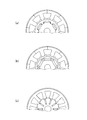
- an example in which the present invention is applied to an IPM motor having a configuration as shown in FIG. 2 has been described.
- the present invention is applicable to all magnet-embedded motors.
- the present invention can also be applied to an IPM motor having a configuration as shown in FIGS.
- FIGS In the above-described embodiment, an example is shown in which the plate thickness of both the stator core plate 17 and the rotor core plate 18 is 0.5 mm.
- the plate thickness of both plates is not limited to 0.5 mm.
- both the stator core plate 17 and the rotor core plate 18 may not have the same thickness.
- the overhang amounts X1 and X2 are preferably about 1 to 2 on the basis of the thickness of the rotor core plate 18.
- the present invention can be widely applied to other in-vehicle electric devices, electric products such as hybrid vehicles, electric vehicles, and air conditioners, in addition to the drive source of the electric power steering device.
Landscapes
- Engineering & Computer Science (AREA)
- Power Engineering (AREA)
- Permanent Field Magnets Of Synchronous Machinery (AREA)
- Iron Core Of Rotating Electric Machines (AREA)
- Brushless Motors (AREA)
- Permanent Magnet Type Synchronous Machine (AREA)
Priority Applications (3)
| Application Number | Priority Date | Filing Date | Title |
|---|---|---|---|
| EP14833881.7A EP3032717A4 (en) | 2013-08-05 | 2014-08-01 | Brushless motor |
| US14/909,612 US20160197541A1 (en) | 2013-08-05 | 2014-08-01 | Brushless motor |
| CN201480042566.9A CN105684279B (zh) | 2013-08-05 | 2014-08-01 | 无刷电机 |
Applications Claiming Priority (2)
| Application Number | Priority Date | Filing Date | Title |
|---|---|---|---|
| JP2013-161967 | 2013-08-05 | ||
| JP2013161967A JP6257212B2 (ja) | 2013-08-05 | 2013-08-05 | ブラシレスモータ |
Publications (1)
| Publication Number | Publication Date |
|---|---|
| WO2015019948A1 true WO2015019948A1 (ja) | 2015-02-12 |
Family
ID=52461284
Family Applications (1)
| Application Number | Title | Priority Date | Filing Date |
|---|---|---|---|
| PCT/JP2014/070311 Ceased WO2015019948A1 (ja) | 2013-08-05 | 2014-08-01 | ブラシレスモータ |
Country Status (5)
| Country | Link |
|---|---|
| US (1) | US20160197541A1 (enExample) |
| EP (1) | EP3032717A4 (enExample) |
| JP (1) | JP6257212B2 (enExample) |
| CN (1) | CN105684279B (enExample) |
| WO (1) | WO2015019948A1 (enExample) |
Cited By (1)
| Publication number | Priority date | Publication date | Assignee | Title |
|---|---|---|---|---|
| WO2016199226A1 (ja) * | 2015-06-09 | 2016-12-15 | 三菱電機株式会社 | 圧縮機用電動機、圧縮機、および冷凍サイクル装置 |
Families Citing this family (12)
| Publication number | Priority date | Publication date | Assignee | Title |
|---|---|---|---|---|
| CN104514987B (zh) * | 2014-12-19 | 2017-02-22 | 清华大学 | 管道三维漏磁成像缺陷量化方法 |
| CN105071568B (zh) * | 2015-08-18 | 2018-05-18 | 广东美芝制冷设备有限公司 | 电机和具有其的压缩机 |
| JP6436065B2 (ja) * | 2015-11-18 | 2018-12-12 | トヨタ自動車株式会社 | 回転電機 |
| JP6616232B2 (ja) | 2016-04-25 | 2019-12-04 | ファナック株式会社 | 固定子鉄心を有する回転電機、及びそれを備える工作機械 |
| GB2553362A (en) * | 2016-09-05 | 2018-03-07 | Edwards Ltd | Vacuum pump assembly |
| CN109546832B (zh) * | 2017-09-21 | 2021-08-10 | 德昌电机(深圳)有限公司 | 无刷直流电机及其双离合变速器 |
| US10385951B2 (en) | 2017-10-04 | 2019-08-20 | Schaeffler Technologies AG & Co. KG | Electric axle assembly |
| US10734876B2 (en) | 2018-03-19 | 2020-08-04 | Denso International America, Inc. | Brushless motor for HVAC system |
| CN108808918A (zh) * | 2018-06-11 | 2018-11-13 | 宝龙电子集团有限公司 | 一种驱动马达 |
| CN109861426B (zh) * | 2019-03-18 | 2021-07-27 | 东南大学 | 一种转子磁场正弦化永磁磁阻同步电机转子结构 |
| JP2021061677A (ja) * | 2019-10-07 | 2021-04-15 | 三菱電機株式会社 | 回転電機 |
| JP7459155B2 (ja) * | 2022-03-07 | 2024-04-01 | 三菱電機株式会社 | 回転電機及びその界磁子製造方法 |
Citations (6)
| Publication number | Priority date | Publication date | Assignee | Title |
|---|---|---|---|---|
| JPH11234931A (ja) * | 1998-02-19 | 1999-08-27 | Hitachi Ltd | 永久磁石式回転電機 |
| JP2004194489A (ja) * | 2002-12-13 | 2004-07-08 | Mitsuba Corp | ブラシレスモータ |
| JP2008160931A (ja) | 2006-12-21 | 2008-07-10 | Brother Ind Ltd | モータ |
| JP2010045873A (ja) * | 2008-08-08 | 2010-02-25 | Fuji Electric Systems Co Ltd | 高効率永久磁石式電動機 |
| JP2010051150A (ja) | 2008-08-25 | 2010-03-04 | Mitsuba Corp | ブラシレスモータ |
| JP2012120326A (ja) * | 2010-11-30 | 2012-06-21 | Fujitsu General Ltd | 磁石埋め込み型回転子、電動機及び電動機の組立方法 |
Family Cites Families (6)
| Publication number | Priority date | Publication date | Assignee | Title |
|---|---|---|---|---|
| CN100536288C (zh) * | 1999-07-16 | 2009-09-02 | 松下电器产业株式会社 | 永久磁铁同步电动机 |
| JP4495443B2 (ja) * | 2003-11-05 | 2010-07-07 | 山洋電気株式会社 | 同期モータとその回転制御方法、及び、同期モータ用インバータ |
| KR100624730B1 (ko) * | 2005-04-04 | 2006-09-20 | 엘지전자 주식회사 | 모터 |
| KR101225164B1 (ko) * | 2005-12-30 | 2013-01-22 | 삼성전자주식회사 | 브러쉬리스 직류 모터 |
| US7741750B1 (en) * | 2008-12-29 | 2010-06-22 | Tesla Motors, Inc. | Induction motor with improved torque density |
| JP5363520B2 (ja) * | 2011-03-04 | 2013-12-11 | 株式会社日立産機システム | 永久磁石同期機 |
-
2013
- 2013-08-05 JP JP2013161967A patent/JP6257212B2/ja active Active
-
2014
- 2014-08-01 US US14/909,612 patent/US20160197541A1/en not_active Abandoned
- 2014-08-01 CN CN201480042566.9A patent/CN105684279B/zh not_active Expired - Fee Related
- 2014-08-01 WO PCT/JP2014/070311 patent/WO2015019948A1/ja not_active Ceased
- 2014-08-01 EP EP14833881.7A patent/EP3032717A4/en not_active Withdrawn
Patent Citations (6)
| Publication number | Priority date | Publication date | Assignee | Title |
|---|---|---|---|---|
| JPH11234931A (ja) * | 1998-02-19 | 1999-08-27 | Hitachi Ltd | 永久磁石式回転電機 |
| JP2004194489A (ja) * | 2002-12-13 | 2004-07-08 | Mitsuba Corp | ブラシレスモータ |
| JP2008160931A (ja) | 2006-12-21 | 2008-07-10 | Brother Ind Ltd | モータ |
| JP2010045873A (ja) * | 2008-08-08 | 2010-02-25 | Fuji Electric Systems Co Ltd | 高効率永久磁石式電動機 |
| JP2010051150A (ja) | 2008-08-25 | 2010-03-04 | Mitsuba Corp | ブラシレスモータ |
| JP2012120326A (ja) * | 2010-11-30 | 2012-06-21 | Fujitsu General Ltd | 磁石埋め込み型回転子、電動機及び電動機の組立方法 |
Non-Patent Citations (1)
| Title |
|---|
| See also references of EP3032717A4 |
Cited By (7)
| Publication number | Priority date | Publication date | Assignee | Title |
|---|---|---|---|---|
| WO2016199226A1 (ja) * | 2015-06-09 | 2016-12-15 | 三菱電機株式会社 | 圧縮機用電動機、圧縮機、および冷凍サイクル装置 |
| JPWO2016199226A1 (ja) * | 2015-06-09 | 2017-09-07 | 三菱電機株式会社 | 圧縮機用電動機、圧縮機、および冷凍サイクル装置 |
| CN107534370A (zh) * | 2015-06-09 | 2018-01-02 | 三菱电机株式会社 | 压缩机用电动机、压缩机及制冷循环装置 |
| EP3309939A4 (en) * | 2015-06-09 | 2019-01-16 | Mitsubishi Electric Corporation | COMPRESSOR ELECTRIC MOTOR, COMPRESSOR AND COLD CIRCULATOR |
| CN111342632A (zh) * | 2015-06-09 | 2020-06-26 | 三菱电机株式会社 | 压缩机用电动机、压缩机及制冷循环装置 |
| US10900696B2 (en) | 2015-06-09 | 2021-01-26 | Mitsubishi Electric Corporation | Electric motor for compressor, compressor, and refrigeration cycle device |
| CN111342632B (zh) * | 2015-06-09 | 2022-05-10 | 三菱电机株式会社 | 压缩机用电动机、压缩机及制冷循环装置 |
Also Published As
| Publication number | Publication date |
|---|---|
| CN105684279A (zh) | 2016-06-15 |
| EP3032717A1 (en) | 2016-06-15 |
| US20160197541A1 (en) | 2016-07-07 |
| CN105684279B (zh) | 2019-02-22 |
| JP2015033244A (ja) | 2015-02-16 |
| JP6257212B2 (ja) | 2018-01-10 |
| EP3032717A4 (en) | 2017-04-19 |
Similar Documents
| Publication | Publication Date | Title |
|---|---|---|
| JP6257212B2 (ja) | ブラシレスモータ | |
| CN102629809B (zh) | 永磁式旋转电机 | |
| US9490673B2 (en) | Rotor of magnet-assisted reluctance motor and brushless motor | |
| JP6388705B2 (ja) | 回転電機の回転子、及びモータ | |
| JP5480106B2 (ja) | 回転電機 | |
| JP6226867B2 (ja) | ブラシレスモータ及びブラシレスモータ用ロータ | |
| CN105409094B (zh) | 定子的制造方法、旋转电机的制造方法、电动助力转向装置的制造方法 | |
| EP3200318A1 (en) | Brushless motor | |
| JP6234558B2 (ja) | 永久磁石型モータ | |
| WO2013161474A1 (ja) | 永久磁石回転電機及びそれを用いた電動車両 | |
| JP2014239633A (ja) | モータ用ロータコア及びブラシレスモータ | |
| WO2015151344A1 (ja) | 永久磁石式ブラシレスモータ | |
| CN102790458A (zh) | 永磁辅助同步磁阻电机转子及其制造方法和电机 | |
| WO2016035533A1 (ja) | 回転電機のステータ、及びこれを備えた回転電機 | |
| JP2013126291A (ja) | ブラシレスモータおよび電動パワーステアリング装置 | |
| JP2014007939A (ja) | ブラシレスモータ | |
| JP2014107939A (ja) | ブラシレスモータ | |
| JP2011188685A (ja) | 永久磁石型電動機 | |
| JP2013207946A (ja) | 回転電機 | |
| JP2014093914A (ja) | ブラシレスモータ | |
| JP6695241B2 (ja) | ブラシレスモータ | |
| WO2007123058A1 (ja) | モータ | |
| JP2014082935A (ja) | 回転電機の固定子、およびこれを備えた回転電機 | |
| JP6664890B2 (ja) | 界磁巻線型駆動モータの回転子 | |
| JP6474283B2 (ja) | ブラシレスモータ |
Legal Events
| Date | Code | Title | Description |
|---|---|---|---|
| 121 | Ep: the epo has been informed by wipo that ep was designated in this application |
Ref document number: 14833881 Country of ref document: EP Kind code of ref document: A1 |
|
| WWE | Wipo information: entry into national phase |
Ref document number: 14909612 Country of ref document: US |
|
| WWE | Wipo information: entry into national phase |
Ref document number: 2014833881 Country of ref document: EP |
|
| NENP | Non-entry into the national phase |
Ref country code: DE |