WO2015019872A1 - ネジセット - Google Patents
ネジセット Download PDFInfo
- Publication number
- WO2015019872A1 WO2015019872A1 PCT/JP2014/069717 JP2014069717W WO2015019872A1 WO 2015019872 A1 WO2015019872 A1 WO 2015019872A1 JP 2014069717 W JP2014069717 W JP 2014069717W WO 2015019872 A1 WO2015019872 A1 WO 2015019872A1
- Authority
- WO
- WIPO (PCT)
- Prior art keywords
- screw
- nut
- fixing
- female
- screw portion
- Prior art date
- Legal status (The legal status is an assumption and is not a legal conclusion. Google has not performed a legal analysis and makes no representation as to the accuracy of the status listed.)
- Ceased
Links
Images


Classifications
-
- F—MECHANICAL ENGINEERING; LIGHTING; HEATING; WEAPONS; BLASTING
- F16—ENGINEERING ELEMENTS AND UNITS; GENERAL MEASURES FOR PRODUCING AND MAINTAINING EFFECTIVE FUNCTIONING OF MACHINES OR INSTALLATIONS; THERMAL INSULATION IN GENERAL
- F16B—DEVICES FOR FASTENING OR SECURING CONSTRUCTIONAL ELEMENTS OR MACHINE PARTS TOGETHER, e.g. NAILS, BOLTS, CIRCLIPS, CLAMPS, CLIPS OR WEDGES; JOINTS OR JOINTING
- F16B41/00—Measures against loss of bolts, nuts, or pins; Measures against unauthorised operation of bolts, nuts or pins
- F16B41/005—Measures against unauthorised operation of bolts, nuts or pins
-
- F—MECHANICAL ENGINEERING; LIGHTING; HEATING; WEAPONS; BLASTING
- F16—ENGINEERING ELEMENTS AND UNITS; GENERAL MEASURES FOR PRODUCING AND MAINTAINING EFFECTIVE FUNCTIONING OF MACHINES OR INSTALLATIONS; THERMAL INSULATION IN GENERAL
- F16B—DEVICES FOR FASTENING OR SECURING CONSTRUCTIONAL ELEMENTS OR MACHINE PARTS TOGETHER, e.g. NAILS, BOLTS, CIRCLIPS, CLAMPS, CLIPS OR WEDGES; JOINTS OR JOINTING
- F16B23/00—Specially shaped nuts or heads of bolts or screws for rotations by a tool
- F16B23/0092—Specially shaped nuts or heads of bolts or screws for rotations by a tool with a head engageable by two or more different tools
Definitions
- This invention relates to a screw set capable of fixing two members in an anti-theft state.
- Patent Document 1 This type of anti-theft technology is disclosed in Patent Document 1.
- the first member is placed on the second member.
- a bolt or nut is tightened from the upper surface of the first member to fix the first member on the second member.
- a cap-shaped antitheft device made of synthetic resin is attached to the head or nut of the bolt.
- This antitheft tool is formed in a cylindrical shape. For this reason, a bolt or a nut cannot be rotated using a tool.
- the first member must be fixed on the second member with a bolt or nut, and then the antitheft device needs to be mounted on the head or nut of the bolt by hitting with a hammer. For this reason, the operation of fixing the first member on the second member is a complicated and time-consuming operation.
- An object of the present invention is to provide a screw set in which two members can be easily fixed in an anti-theft state.
- a screw main body having a fixing screw portion and a nut screwed to a male screw portion formed on the outer peripheral surface of the screw main body are provided. At least one of the threaded portion and the female threaded portion of the nut has a sliding means to make the screwing force of the male threaded portion and the female threaded portion weaker than the screwing force of the fixing screw portion.
- the female screw portion of the nut is screwed into the male screw portion of the screw body.
- the general-purpose tool is engaged with the nut and tightened, whereby the fixing screw portion of the screw body is tightened to the fixing bolt or the fixing nut.
- two members can be fixed easily.
- the screwing force between the male screw portion of the screw body and the female screw portion of the nut is weakened by the sliding means than the screwing force of the fixing screw portion with respect to the fixing bolt or the fixing nut.
- Sectional drawing which shows another modification Sectional drawing which shows another modification.
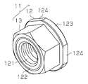
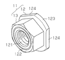
- the female screw set 11 includes a screw body 12 and a nut 13.
- the nut 13 is formed in a hexagon so that a general-purpose tool such as a wrench can be used.
- a fixing screw portion 121 made of a female screw is formed at the center of the screw body 12.
- a male screw portion 122 is formed on the outer peripheral surface of the screw body 12.
- the male screw part 122 is screwed into the female screw part 131 of the nut 13.
- a flange 123 is formed on the edge of the screw body 12.
- the flange 123 has a shape corresponding to a dedicated tool.
- three flat portions 124 are formed on the outer peripheral surface of the flange 123 to enable the use of a dedicated tool.
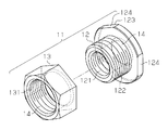
- the female screw set 11 is distributed in the market with the nut 13 screwed into the male screw portion 122 of the screw main body 12.
- At least one of the male screw part 122 and the female screw part 131 has a sliding structure 14 as a sliding means in order to make the screwing force of the male screw part 122 and the female screw part 131 weaker than the screwing force in the fixing screw part 121.
- the sliding structure 14 is formed only on the nut 13.
- the sliding arrangement 14 comprises a fluorine coating.
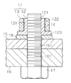
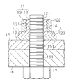
- FIG. 3 shows a state in which the first member 15 such as a solar cell panel is fixed on the second member 16 using the female screw set 11.
- the first member 15 is placed on the second member 16.
- the fixing bolt 17 is inserted into the bolt insertion hole 161 of the second member 16 and the bolt insertion hole 151 of the first member 15 from the lower surface of the second member 16.
- the washer 18 is fitted to the tip of the fixing bolt 17, and then the female screw set 11 is screwed to the tip of the fixing bolt 17.
- the washer 18 and the female screw set 11 are mounted above the first member 15.
- the washer 18 may not be used.
- the male screw portion 122 of the screw body 12 and the female screw portion 131 of the nut 13 are screwed together in advance. Thereby, the screw main body 12 and the nut 13 of the female screw set 11 are integrated. Then, the fixing screw portion 121 of the screw body 12 is fastened to the fixing bolt 17 by engaging the general-purpose tool with the nut 13 and tightening. Thus, the first member 15 is fixed to the second member 16.
- the dedicated tool When the first member 15 is repaired and inspected, the dedicated tool may be engaged with the flange 123 of the screw body 12 and rotated. Thereby, tightening of the fixing screw portion 121 with respect to the fixing bolt 17 can be loosened, and the first member 15 can be detached from the second member 16.
- the female screw set 11 includes a screw body 12 and a nut 13.
- the screw body 12 has a fixing screw part 121.
- a male screw portion 122 into which the female screw portion 131 of the nut 13 is screwed is formed on the outer peripheral surface of the screw body 12.
- a flange 123 is formed on the screw body 12.
- the flange 123 has a shape corresponding to a dedicated tool.
- At least one of the male screw part 122 and the female screw part 131 has a sliding structure 14 in order to make the screwing force of the male screw part 122 and the female screw part 131 weaker than the screwing force of the fixing screw part 121.
- the first member 15 can be easily fixed to the second member 16.
- the screwing force between the male screw part 122 of the screw main body 12 and the female screw part 131 of the nut 13 is weaker than the screwing force of the fixing screw part 121 to the fixing bolt 17. Yes.
- the nut 13 is only loosened with respect to the screw main body 12. Therefore, according to the female screw set 11 of the first embodiment, the first member 15 can be easily fixed to the second member 16, and the theft of the first member 15 can be prevented with a simple configuration.
- the sliding structure 14 is made of a fluorine coating. For this reason, the number of parts constituting the female screw set 11 does not increase. That is, with a simple configuration, the screwing force between the male screw portion 122 and the female screw portion 131 can be made weaker than the screwing force of the fixing screw portion 121 with respect to the fixing bolt 17. (Second Embodiment) Next, a second embodiment in which the screw set of the present invention is embodied in the male screw set 21 will be described with reference to FIGS. Note that the detailed description of the same parts in the second embodiment as those in the first embodiment is omitted.
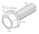
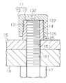
- the male screw set 21 includes a screw body 12 and a nut 13.
- the screw body 12 has a fixing screw portion 121 made of a male screw.
- the screw main body 12 has a male screw portion 122 on the opposite side of the fixing screw portion 121 to which the female screw portion 131 of the nut 13 is screwed.
- the screw body 12 has a flange 123 between the fixing screw portion 121 and the male screw portion 122.
- the flange 123 has a shape corresponding to a dedicated tool.
- the male screw portion 122 and the female screw portion 131 has a sliding means for making the screwing force of the male screw portion 122 and the female screw portion 131 weaker than the screwing force of the fixing screw portion 121.
- the sliding structure 14 is formed only on the nut 13.
- the sliding arrangement 14 comprises a fluorine coating.
- the male screw set 21 is distributed in the market in a state where the nut 13 is screwed to the male screw portion 122 of the head of the screw main body 12.
- FIG. 6 shows a state in which the first member 15 is fixed on the second member 16 using the male screw set 21.
- the first member 15 is placed on the second member 16.
- the washer 18 is placed at a position corresponding to the bolt insertion hole 151 on the first member 15.
- the fixing screw portion 121 of the male screw set 21 is inserted into the bolt insertion hole 151 of the first member 15 and the bolt insertion hole 161 of the second member 16. Placement of the washer 18 and insertion of the male screw set 21 are performed above the first member 15.
- the washer 18 may not be used.
- the fixing nut 22 is screwed into the fixing screw portion 121 from below the second member 16.
- the male screw portion 122 of the screw body 12 and the female screw portion 131 of the nut 13 are screwed together in advance.
- the screw main body 12 and the nut 13 of the male screw set 21 are integrated.
- the fixing screw portion 121 of the screw body 12 is fastened to the fixing nut 22 by engaging and tightening the general-purpose tool to the nut 13.
- the first member 15 is fixed to the second member 16.
- the dedicated tool When the first member 15 is repaired and inspected, the dedicated tool may be engaged with the flange 123 on the screw body 12 and rotated. Thereby, the tightening of the fixing screw portion 121 with respect to the fixing nut 22 can be loosened, and the first member 15 can be removed from the second member 16.
- the fixing bolt 17 may be fixed to the second member 16, and the fixing screw portion 121 of the female screw set 11 may be screwed into the fixing bolt 17.
- a fixing female screw may be formed on the second member 16 instead of the fixing nut 22.
- the fixing screw portion 121 of the male screw set 21 is screwed into the fixing female screw of the second member 16.
- the sliding means may be configured using a material having a low coefficient of friction such as molybdenum disulfide or lubricating oil or a lubricity instead of the fluorine coating.
- the clearance between the male screw portion 122 of the screw main body 12 and the female screw portion 131 of the nut 13 is set such that the fixing screw portion 121 of the screw main body 12 and the fixing bolt 17 or the fixing nut 22 are
- the sliding means may be configured to be larger than the clearance between the two.
- an adhesive is applied between the fixing screw portion 121 of the screw main body 12 and the fixing bolt 17 or the fixing nut 22 to make it difficult to come off, and the screwing force between the male screw portion 122 and the female screw portion 131 is changed. It may be weaker than that of the part.
- At least one of the flange 123 of the screw body 12 and the washer 18 that is in contact with the flange 123 may be provided with friction means to provide resistance to rotation of the screw body 12. If the washer 18 is not provided, friction means may be applied to the first member 15. As the friction means, irregularities may be formed on the contact surfaces of the flange 123, the washer 18, the first member 15, and the like, or roughening may be performed. Further, a material having a high friction coefficient such as rubber may be disposed on the contact surfaces of the flange 123, the washer 18, the first member 15, and the like. With this configuration, the screwing force between the male screw portion 122 and the female screw portion 131 can be made weaker than that of other portions.
- the number of the plane parts 124 for exclusive tools may be 2 or less, or 4 or more.
- the outer peripheral surface of the flange 123 may be formed only by the flat portion 124.
- the outer peripheral surface of the flange 123 is a circumferential surface.
- a portion other than the flat portion 124 may be rounded on the outer peripheral surface of the flange 123. In this case, the roundness is formed at the edge of the flange 123 opposite to the first member 15. Further, as indicated by a two-dot chain line L in FIG. 8, a portion other than the flat portion 124 may be formed in a tapered shape on the outer peripheral surface of the flange 123. In this way, the use of a general-purpose tool can be made more difficult. These configurations may be applied to the flange 123 that does not have the flat surface portion 124.
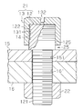
- the female screw set 11 may be formed so that the flange 123 of the screw body 12 is omitted and a gap 25 is provided between the nut 13 and the first member 15.
- a non-threaded portion 125 is formed in the lower portion of the male screw portion 122, or the inner back surface of the nut 13 is formed on the end surface of the male screw portion 122. May be brought into contact with each other.
- the outer peripheral surface of the nut 13 is preferably a circumferential surface, and a plus or minus groove 132 for a driver or a hexagonal hole for a wrench is preferably formed on the top surface of the nut 13. .
Landscapes
- Engineering & Computer Science (AREA)
- General Engineering & Computer Science (AREA)
- Mechanical Engineering (AREA)
- Connection Of Plates (AREA)
- Bolts, Nuts, And Washers (AREA)
Priority Applications (1)
| Application Number | Priority Date | Filing Date | Title |
|---|---|---|---|
| EP14835238.8A EP3032120B1 (en) | 2013-08-05 | 2014-07-25 | Screw set |
Applications Claiming Priority (2)
| Application Number | Priority Date | Filing Date | Title |
|---|---|---|---|
| JP2013162501A JP6151124B2 (ja) | 2013-08-05 | 2013-08-05 | ネジセット |
| JP2013-162501 | 2013-08-05 |
Publications (1)
| Publication Number | Publication Date |
|---|---|
| WO2015019872A1 true WO2015019872A1 (ja) | 2015-02-12 |
Family
ID=52461211
Family Applications (1)
| Application Number | Title | Priority Date | Filing Date |
|---|---|---|---|
| PCT/JP2014/069717 Ceased WO2015019872A1 (ja) | 2013-08-05 | 2014-07-25 | ネジセット |
Country Status (3)
| Country | Link |
|---|---|
| EP (1) | EP3032120B1 (enExample) |
| JP (1) | JP6151124B2 (enExample) |
| WO (1) | WO2015019872A1 (enExample) |
Families Citing this family (2)
| Publication number | Priority date | Publication date | Assignee | Title |
|---|---|---|---|---|
| JP6580088B2 (ja) | 2017-06-09 | 2019-09-25 | 株式会社東海理化電機製作所 | ウェビング巻取装置 |
| KR102278631B1 (ko) * | 2019-07-03 | 2021-07-16 | 윤준현 | 토크 제한 기능을 갖는 회전 결합구 |
Citations (6)
| Publication number | Priority date | Publication date | Assignee | Title |
|---|---|---|---|---|
| JPS5632118U (enExample) * | 1979-08-21 | 1981-03-28 | ||
| JP3069163U (ja) * | 1999-05-06 | 2000-06-06 | 高義 大石 | 防犯対応ボルト |
| US20070092352A1 (en) * | 2005-10-21 | 2007-04-26 | Nilsen Martin J | Tamper proof fastener |
| JP2009108934A (ja) * | 2007-10-30 | 2009-05-21 | Honda Motor Co Ltd | ボルト |
| JP2009275714A (ja) * | 2008-05-12 | 2009-11-26 | Hama System:Kk | ボルト |
| JP2012241340A (ja) | 2011-05-16 | 2012-12-10 | Chuetsu Seito Kk | 盗難防止具及びボルト又はナット固定物品の盗難防止方法 |
-
2013
- 2013-08-05 JP JP2013162501A patent/JP6151124B2/ja active Active
-
2014
- 2014-07-25 WO PCT/JP2014/069717 patent/WO2015019872A1/ja not_active Ceased
- 2014-07-25 EP EP14835238.8A patent/EP3032120B1/en active Active
Patent Citations (6)
| Publication number | Priority date | Publication date | Assignee | Title |
|---|---|---|---|---|
| JPS5632118U (enExample) * | 1979-08-21 | 1981-03-28 | ||
| JP3069163U (ja) * | 1999-05-06 | 2000-06-06 | 高義 大石 | 防犯対応ボルト |
| US20070092352A1 (en) * | 2005-10-21 | 2007-04-26 | Nilsen Martin J | Tamper proof fastener |
| JP2009108934A (ja) * | 2007-10-30 | 2009-05-21 | Honda Motor Co Ltd | ボルト |
| JP2009275714A (ja) * | 2008-05-12 | 2009-11-26 | Hama System:Kk | ボルト |
| JP2012241340A (ja) | 2011-05-16 | 2012-12-10 | Chuetsu Seito Kk | 盗難防止具及びボルト又はナット固定物品の盗難防止方法 |
Also Published As
| Publication number | Publication date |
|---|---|
| JP2015031362A (ja) | 2015-02-16 |
| EP3032120A4 (en) | 2016-08-17 |
| EP3032120B1 (en) | 2018-11-14 |
| EP3032120A1 (en) | 2016-06-15 |
| JP6151124B2 (ja) | 2017-06-21 |
Similar Documents
| Publication | Publication Date | Title |
|---|---|---|
| JP3187298U (ja) | ダブルロックナット | |
| US11274696B2 (en) | Fastening structure | |
| EP3054174A1 (en) | Bolt | |
| US20180119722A1 (en) | Bolt with Locked Nut | |
| JP6452795B2 (ja) | ロックナット | |
| US8979457B2 (en) | Device for fastening | |
| JP2013087947A (ja) | クロスボルト緩み止め組み合わせナット | |
| JP6202601B2 (ja) | 分割ブラインドナット | |
| WO2014116319A1 (en) | Fastener | |
| JP2016526645A (ja) | 締結要素および締結アセンブリ | |
| JP2012102783A (ja) | 締付固定具 | |
| AU2017276239B2 (en) | Fastening device | |
| JP2012172780A (ja) | 締結具の緩み止め装置 | |
| WO2015019872A1 (ja) | ネジセット | |
| JP2012247023A (ja) | アダプタ用ロックナットの固定構造 | |
| JP2013032820A (ja) | 締付ボルト | |
| JP3206838U (ja) | ネジセット | |
| JP2014088951A (ja) | ねじの緩み止部材 | |
| JP2015105755A (ja) | 車輪用締結具 | |
| JP5825724B2 (ja) | ショックアブソーバの製造方法 | |
| JP3179874U (ja) | ボルトとナットとからなる締結具 | |
| JP3138712U (ja) | タッピンボルト | |
| JP3199619U (ja) | 緩み止めナット | |
| US6315409B1 (en) | Fixtures and fitting structure for eyeglass lens | |
| JP3204727U (ja) | ロックナット |
Legal Events
| Date | Code | Title | Description |
|---|---|---|---|
| 121 | Ep: the epo has been informed by wipo that ep was designated in this application |
Ref document number: 14835238 Country of ref document: EP Kind code of ref document: A1 |
|
| WWE | Wipo information: entry into national phase |
Ref document number: 2014835238 Country of ref document: EP |
|
| NENP | Non-entry into the national phase |
Ref country code: DE |