WO2015019872A1 - Screw set - Google Patents
Screw set Download PDFInfo
- Publication number
- WO2015019872A1 WO2015019872A1 PCT/JP2014/069717 JP2014069717W WO2015019872A1 WO 2015019872 A1 WO2015019872 A1 WO 2015019872A1 JP 2014069717 W JP2014069717 W JP 2014069717W WO 2015019872 A1 WO2015019872 A1 WO 2015019872A1
- Authority
- WO
- WIPO (PCT)
- Prior art keywords
- screw
- nut
- fixing
- female
- screw portion
- Prior art date
Links
- 230000002093 peripheral effect Effects 0.000 claims abstract description 13
- YCKRFDGAMUMZLT-UHFFFAOYSA-N Fluorine atom Chemical compound [F] YCKRFDGAMUMZLT-UHFFFAOYSA-N 0.000 claims description 5
- 239000011248 coating agent Substances 0.000 claims description 5
- 238000000576 coating method Methods 0.000 claims description 5
- 239000011737 fluorine Substances 0.000 claims description 5
- 229910052731 fluorine Inorganic materials 0.000 claims description 5
- 238000003780 insertion Methods 0.000 description 6
- 230000037431 insertion Effects 0.000 description 6
- 238000012986 modification Methods 0.000 description 4
- 230000004048 modification Effects 0.000 description 4
- 238000000034 method Methods 0.000 description 3
- 230000000694 effects Effects 0.000 description 2
- 239000000463 material Substances 0.000 description 2
- 239000000853 adhesive Substances 0.000 description 1
- 230000001070 adhesive effect Effects 0.000 description 1
- 239000010687 lubricating oil Substances 0.000 description 1
- CWQXQMHSOZUFJS-UHFFFAOYSA-N molybdenum disulfide Chemical compound S=[Mo]=S CWQXQMHSOZUFJS-UHFFFAOYSA-N 0.000 description 1
- 229910052982 molybdenum disulfide Inorganic materials 0.000 description 1
- 238000007788 roughening Methods 0.000 description 1
- 229920003002 synthetic resin Polymers 0.000 description 1
- 239000000057 synthetic resin Substances 0.000 description 1
Images


Classifications
-
- F—MECHANICAL ENGINEERING; LIGHTING; HEATING; WEAPONS; BLASTING
- F16—ENGINEERING ELEMENTS AND UNITS; GENERAL MEASURES FOR PRODUCING AND MAINTAINING EFFECTIVE FUNCTIONING OF MACHINES OR INSTALLATIONS; THERMAL INSULATION IN GENERAL
- F16B—DEVICES FOR FASTENING OR SECURING CONSTRUCTIONAL ELEMENTS OR MACHINE PARTS TOGETHER, e.g. NAILS, BOLTS, CIRCLIPS, CLAMPS, CLIPS OR WEDGES; JOINTS OR JOINTING
- F16B41/00—Measures against loss of bolts, nuts, or pins; Measures against unauthorised operation of bolts, nuts or pins
- F16B41/005—Measures against unauthorised operation of bolts, nuts or pins
-
- F—MECHANICAL ENGINEERING; LIGHTING; HEATING; WEAPONS; BLASTING
- F16—ENGINEERING ELEMENTS AND UNITS; GENERAL MEASURES FOR PRODUCING AND MAINTAINING EFFECTIVE FUNCTIONING OF MACHINES OR INSTALLATIONS; THERMAL INSULATION IN GENERAL
- F16B—DEVICES FOR FASTENING OR SECURING CONSTRUCTIONAL ELEMENTS OR MACHINE PARTS TOGETHER, e.g. NAILS, BOLTS, CIRCLIPS, CLAMPS, CLIPS OR WEDGES; JOINTS OR JOINTING
- F16B23/00—Specially shaped nuts or heads of bolts or screws for rotations by a tool
- F16B23/0092—Specially shaped nuts or heads of bolts or screws for rotations by a tool with a head engageable by two or more different tools
Landscapes
- Engineering & Computer Science (AREA)
- General Engineering & Computer Science (AREA)
- Mechanical Engineering (AREA)
- Connection Of Plates (AREA)
- Bolts, Nuts, And Washers (AREA)
Abstract
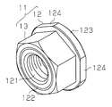
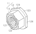
A female screw set (11) is provided with a screw body (12) having an affixing thread section (121) and also with a nut (13). The nut (13) is engaged with a male thread section (122) formed on the outer peripheral surface of the screw body (12). A flange (123) is formed on the screw body (12). The flange (123) has a shape corresponding to a dedicated tool. The male thread section (122) and/or the female thread section (131) of the nut (13) has a sliding structure (14) in order to make the engagement force between the male thread section (122) and the female thread section (131) less than the engagement force of the affixing thread section (121).
Description
この発明は、二つの部材を盗難防止状態にして固定することのできるネジセットに関する。
This invention relates to a screw set capable of fixing two members in an anti-theft state.
この種の盗難防止技術が、特許文献1に開示されている。この文献に開示の従来技術によれば、まず、第2部材上に第1部材を載置する。次に、第1部材の上面からボルト又はナットを締め付けて、第1部材を第2部材上に固定する。続いて、第1部材を第2部材上に固定した状態で、合成樹脂からなるキャップ状の盗難防止具を、ボルトの頭部又はナットに被せて装着する。この盗難防止具は、円筒状に形成されている。このため、工具を用いてボルト又はナットを回転させることができない。
This type of anti-theft technology is disclosed in Patent Document 1. According to the prior art disclosed in this document, first, the first member is placed on the second member. Next, a bolt or nut is tightened from the upper surface of the first member to fix the first member on the second member. Subsequently, in a state where the first member is fixed on the second member, a cap-shaped antitheft device made of synthetic resin is attached to the head or nut of the bolt. This antitheft tool is formed in a cylindrical shape. For this reason, a bolt or a nut cannot be rotated using a tool.
上記従来の盗難防止方法では、ボルト又はナットにより第1部材を第2部材上に固定した後、ハンマで叩いて盗難防止具をボルトの頭部又はナットに装着する必要がある。このため、第2部材上に第1部材を固定する作業は、煩雑でかつ時間を要する作業であった。
In the above conventional antitheft method, the first member must be fixed on the second member with a bolt or nut, and then the antitheft device needs to be mounted on the head or nut of the bolt by hitting with a hammer. For this reason, the operation of fixing the first member on the second member is a complicated and time-consuming operation.
この発明の目的は、二つの部材を盗難防止状態にして固定することが容易であるネジセットを提供することにある。
An object of the present invention is to provide a screw set in which two members can be easily fixed in an anti-theft state.
上記課題を解決するため、本発明の第一の態様によれば、固定用ネジ部を有するネジ本体と、ネジ本体の外周面に形成した雄ネジ部に螺合されるナットとを備え、雄ネジ部及びナットの雌ネジ部の少なくとも一方は、雄ネジ部及び雌ネジ部の螺合力を固定用ネジ部における螺合力より弱くするため、滑動手段を有している。
In order to solve the above-described problem, according to a first aspect of the present invention, a screw main body having a fixing screw portion and a nut screwed to a male screw portion formed on the outer peripheral surface of the screw main body are provided. At least one of the threaded portion and the female threaded portion of the nut has a sliding means to make the screwing force of the male threaded portion and the female threaded portion weaker than the screwing force of the fixing screw portion.
この構成によれば、ネジセットの使用時、ネジ本体の雄ネジ部にナットの雌ネジ部が螺合されている。こうして、ネジ本体とナットとが一体化されている状態で、汎用工具をナットに係合させて締め付けることにより、ネジ本体の固定用ネジ部が固定用ボルト又は固定用ナットに締め付けられる。これにより、二つの部材を容易に固定することができる。この状態では、滑動手段により、ネジ本体の雄ネジ部とナットの雌ネジ部との間の螺合力が、固定用ボルト又は固定用ナットに対する固定用ネジ部の螺合力より弱められている。このため、汎用工具をナットに係合させてネジセット全体を弛めようとしても、ナットがネジ本体に対して弛められるだけで、固定用ボルト又は固定用ナットに対する固定用ネジ部の締め付け状態は維持される。つまり、簡単な構成により、固定された二つの部材のうち一方が取り外されて盗難されることを防止できる。
According to this configuration, when the screw set is used, the female screw portion of the nut is screwed into the male screw portion of the screw body. Thus, in a state where the screw body and the nut are integrated, the general-purpose tool is engaged with the nut and tightened, whereby the fixing screw portion of the screw body is tightened to the fixing bolt or the fixing nut. Thereby, two members can be fixed easily. In this state, the screwing force between the male screw portion of the screw body and the female screw portion of the nut is weakened by the sliding means than the screwing force of the fixing screw portion with respect to the fixing bolt or the fixing nut. For this reason, even if the general-purpose tool is engaged with the nut to loosen the entire screw set, the nut is only loosened with respect to the screw body, and the fixing bolt or the fixing screw portion is tightened against the fixing nut. Is maintained. That is, with a simple configuration, it is possible to prevent one of the two fixed members from being removed and stolen.
(第1実施形態)
以下、本発明のネジセットを雌ネジセットに具体化した第1実施形態について図1~図3を参照して説明する。 (First embodiment)
A first embodiment in which the screw set of the present invention is embodied as a female screw set will be described below with reference to FIGS.
以下、本発明のネジセットを雌ネジセットに具体化した第1実施形態について図1~図3を参照して説明する。 (First embodiment)
A first embodiment in which the screw set of the present invention is embodied as a female screw set will be described below with reference to FIGS.
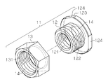
図1及び図2示すように、雌ネジセット11は、ネジ本体12及びナット13を備えている。ナット13は、レンチ等の汎用工具を使用できるよう六角形に形成されている。ネジ本体12の中心には、雌ネジよりなる固定用ネジ部121が形成されている。ネジ本体12の外周面には、雄ネジ部122が形成されている。雄ネジ部122は、ナット13の雌ネジ部131に螺合される。ネジ本体12の端縁には、フランジ123が形成されている。フランジ123は、専用工具に対応する形状を有している。第1実施形態では、専用工具の使用を可能にするため、3つの平面部124がフランジ123の外周面に形成されている。雌ネジセット11は、ネジ本体12の雄ネジ部122にナット13が螺合された状態で、市場に流通している。
1 and 2, the female screw set 11 includes a screw body 12 and a nut 13. The nut 13 is formed in a hexagon so that a general-purpose tool such as a wrench can be used. At the center of the screw body 12, a fixing screw portion 121 made of a female screw is formed. A male screw portion 122 is formed on the outer peripheral surface of the screw body 12. The male screw part 122 is screwed into the female screw part 131 of the nut 13. A flange 123 is formed on the edge of the screw body 12. The flange 123 has a shape corresponding to a dedicated tool. In the first embodiment, three flat portions 124 are formed on the outer peripheral surface of the flange 123 to enable the use of a dedicated tool. The female screw set 11 is distributed in the market with the nut 13 screwed into the male screw portion 122 of the screw main body 12.
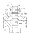
雄ネジ部122及び雌ネジ部131の少なくとも一方は、雄ネジ部122及び雌ネジ部131の螺合力を固定用ネジ部121における螺合力より弱くするため、滑動手段としての滑動構成14を有している。第1実施形態では、滑動構成14がナット13にのみ形成されている。滑動構成14はフッ素コーティングからなる。
At least one of the male screw part 122 and the female screw part 131 has a sliding structure 14 as a sliding means in order to make the screwing force of the male screw part 122 and the female screw part 131 weaker than the screwing force in the fixing screw part 121. ing. In the first embodiment, the sliding structure 14 is formed only on the nut 13. The sliding arrangement 14 comprises a fluorine coating.
次に、雌ネジセット11の使用方法について図3を参照して説明する。
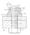
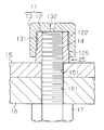
図3は、雌ネジセット11を用いて太陽電池パネル等の第1部材15が第2部材16上に固定されている状態を示す。この場合、まず、第2部材16上に第1部材15を載置する。次に、第2部材16の下面から、第2部材16のボルト挿通孔161と第1部材15のボルト挿通孔151とに固定用ボルト17を挿通する。続いて、第2部材16上に第1部材15を固定した状態で、固定用ボルト17の先端に座金18を嵌めてから、雌ネジセット11を固定用ボルト17の先端に螺合させる。座金18及び雌ネジセット11の装着は、第1部材15の上方で行われる。尚、座金18は使用しなくてもよい。この段階で、ネジ本体12の雄ネジ部122とナット13の雌ネジ部131とが予め螺合されている。これにより、雌ネジセット11のネジ本体12とナット13とが一体化されている。そして、汎用工具をナット13に係合させて締め付けることにより、ネジ本体12の固定用ネジ部121が固定用ボルト17に締め付けられる。こうして、第1部材15が第2部材16に固定される。 Next, a method of using thefemale screw set 11 will be described with reference to FIG.
FIG. 3 shows a state in which thefirst member 15 such as a solar cell panel is fixed on the second member 16 using the female screw set 11. In this case, first, the first member 15 is placed on the second member 16. Next, the fixing bolt 17 is inserted into the bolt insertion hole 161 of the second member 16 and the bolt insertion hole 151 of the first member 15 from the lower surface of the second member 16. Subsequently, with the first member 15 fixed on the second member 16, the washer 18 is fitted to the tip of the fixing bolt 17, and then the female screw set 11 is screwed to the tip of the fixing bolt 17. The washer 18 and the female screw set 11 are mounted above the first member 15. The washer 18 may not be used. At this stage, the male screw portion 122 of the screw body 12 and the female screw portion 131 of the nut 13 are screwed together in advance. Thereby, the screw main body 12 and the nut 13 of the female screw set 11 are integrated. Then, the fixing screw portion 121 of the screw body 12 is fastened to the fixing bolt 17 by engaging the general-purpose tool with the nut 13 and tightening. Thus, the first member 15 is fixed to the second member 16.
図3は、雌ネジセット11を用いて太陽電池パネル等の第1部材15が第2部材16上に固定されている状態を示す。この場合、まず、第2部材16上に第1部材15を載置する。次に、第2部材16の下面から、第2部材16のボルト挿通孔161と第1部材15のボルト挿通孔151とに固定用ボルト17を挿通する。続いて、第2部材16上に第1部材15を固定した状態で、固定用ボルト17の先端に座金18を嵌めてから、雌ネジセット11を固定用ボルト17の先端に螺合させる。座金18及び雌ネジセット11の装着は、第1部材15の上方で行われる。尚、座金18は使用しなくてもよい。この段階で、ネジ本体12の雄ネジ部122とナット13の雌ネジ部131とが予め螺合されている。これにより、雌ネジセット11のネジ本体12とナット13とが一体化されている。そして、汎用工具をナット13に係合させて締め付けることにより、ネジ本体12の固定用ネジ部121が固定用ボルト17に締め付けられる。こうして、第1部材15が第2部材16に固定される。 Next, a method of using the
FIG. 3 shows a state in which the
この状態では、滑動構成14により、ネジ本体12の雄ネジ部122とナット13の雌ネジ部131との間の螺合力が、固定用ボルト17に対する固定用ネジ部121の螺合力より弱められている。このため、汎用工具をナット13に係合させて雌ネジセット11全体を緩めようとしても、ナット13がネジ本体12に対して緩められるだけで、固定用ボルト17に対する固定用ネジ部121の締め付け状態は維持される。このため、雌ネジセット11を固定用ボルト17から取り外すことができない。よって、第1部材15の盗難を防止することができる。
In this state, due to the sliding configuration 14, the screwing force between the male screw part 122 of the screw main body 12 and the female screw part 131 of the nut 13 is weaker than the screwing force of the fixing screw part 121 to the fixing bolt 17. Yes. Therefore, even if the general-purpose tool is engaged with the nut 13 to loosen the entire female screw set 11, the nut 13 is only loosened with respect to the screw main body 12, and the fixing screw portion 121 is tightened with respect to the fixing bolt 17. State is maintained. For this reason, the female screw set 11 cannot be removed from the fixing bolt 17. Accordingly, the first member 15 can be prevented from being stolen.
第1部材15を補修点検する場合、専用工具をネジ本体12のフランジ123に係合させて回転操作すればよい。これにより、固定用ボルト17に対する固定用ネジ部121の締付けを緩めることができ、第1部材15を第2部材16から取り外すことができる。
When the first member 15 is repaired and inspected, the dedicated tool may be engaged with the flange 123 of the screw body 12 and rotated. Thereby, tightening of the fixing screw portion 121 with respect to the fixing bolt 17 can be loosened, and the first member 15 can be detached from the second member 16.
従って、第1実施形態によれば、以下のような効果を得ることができる。
(1)雌ネジセット11は、ネジ本体12及びナット13を備えている。ネジ本体12は、固定用ネジ部121を有している。ネジ本体12の外周面には、ナット13の雌ネジ部131が螺合される雄ネジ部122が形成されている。ネジ本体12には、フランジ123が形成されている。フランジ123は、専用工具に対応する形状を有している。雄ネジ部122及び雌ネジ部131の少なくとも一方は、雄ネジ部122及び雌ネジ部131の螺合力を固定用ネジ部121における螺合力より弱くするため、滑動構成14を有している。 Therefore, according to the first embodiment, the following effects can be obtained.
(1) The female screw set 11 includes ascrew body 12 and a nut 13. The screw body 12 has a fixing screw part 121. On the outer peripheral surface of the screw body 12, a male screw portion 122 into which the female screw portion 131 of the nut 13 is screwed is formed. A flange 123 is formed on the screw body 12. The flange 123 has a shape corresponding to a dedicated tool. At least one of the male screw part 122 and the female screw part 131 has a sliding structure 14 in order to make the screwing force of the male screw part 122 and the female screw part 131 weaker than the screwing force of the fixing screw part 121.
(1)雌ネジセット11は、ネジ本体12及びナット13を備えている。ネジ本体12は、固定用ネジ部121を有している。ネジ本体12の外周面には、ナット13の雌ネジ部131が螺合される雄ネジ部122が形成されている。ネジ本体12には、フランジ123が形成されている。フランジ123は、専用工具に対応する形状を有している。雄ネジ部122及び雌ネジ部131の少なくとも一方は、雄ネジ部122及び雌ネジ部131の螺合力を固定用ネジ部121における螺合力より弱くするため、滑動構成14を有している。 Therefore, according to the first embodiment, the following effects can be obtained.
(1) The female screw set 11 includes a
この構成によれば、ネジ本体12とナット13とが一体化されている状態で、汎用工具をナット13に係合させて締め付けることにより、ネジ本体12の固定用ネジ部121が固定用ボルト17に締め付けられる。こうして、第1部材15を第2部材16に対して容易に固定することができる。この状態では、滑動構成14により、ネジ本体12の雄ネジ部122とナット13の雌ネジ部131との間の螺合力が、固定用ボルト17に対する固定用ネジ部121の螺合力より弱められている。このため、汎用工具を用いて雌ネジセット11全体を緩めようとしても、ナット13がネジ本体12に対して緩められるだけである。よって、第1実施形態の雌ネジセット11によれば、第1部材15を第2部材16に対して容易に固定できると共に、簡単な構成により第1部材15の盗難を防止することもできる。
According to this configuration, when the screw body 12 and the nut 13 are integrated, the general-purpose tool is engaged with the nut 13 and tightened, whereby the fixing screw portion 121 of the screw body 12 is fixed to the fixing bolt 17. Tightened to. Thus, the first member 15 can be easily fixed to the second member 16. In this state, due to the sliding configuration 14, the screwing force between the male screw part 122 of the screw main body 12 and the female screw part 131 of the nut 13 is weaker than the screwing force of the fixing screw part 121 to the fixing bolt 17. Yes. For this reason, even if it is going to loosen the whole female screw set 11 using a general purpose tool, the nut 13 is only loosened with respect to the screw main body 12. Therefore, according to the female screw set 11 of the first embodiment, the first member 15 can be easily fixed to the second member 16, and the theft of the first member 15 can be prevented with a simple configuration.
(2)滑動構成14はフッ素コーティングからなる。このため、雌ネジセット11を構成する部品の数は増えない。つまり、簡単な構成によって、雄ネジ部122と雌ネジ部131との螺合力を固定用ボルト17に対する固定用ネジ部121の螺合力よりも弱くすることができる。
(第2実施形態)
次に、本発明のネジセットを雄ネジセット21に具体化した第2実施形態について図4~図6を参照して説明する。尚、第2実施形態における第1実施形態と同様の部分についてはその詳細な説明を省略する。 (2) The slidingstructure 14 is made of a fluorine coating. For this reason, the number of parts constituting the female screw set 11 does not increase. That is, with a simple configuration, the screwing force between the male screw portion 122 and the female screw portion 131 can be made weaker than the screwing force of the fixing screw portion 121 with respect to the fixing bolt 17.
(Second Embodiment)
Next, a second embodiment in which the screw set of the present invention is embodied in the male screw set 21 will be described with reference to FIGS. Note that the detailed description of the same parts in the second embodiment as those in the first embodiment is omitted.
(第2実施形態)
次に、本発明のネジセットを雄ネジセット21に具体化した第2実施形態について図4~図6を参照して説明する。尚、第2実施形態における第1実施形態と同様の部分についてはその詳細な説明を省略する。 (2) The sliding
(Second Embodiment)
Next, a second embodiment in which the screw set of the present invention is embodied in the male screw set 21 will be described with reference to FIGS. Note that the detailed description of the same parts in the second embodiment as those in the first embodiment is omitted.
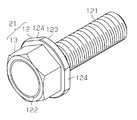
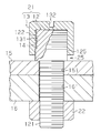
図4~図6に示すように、雄ネジセット21には、ネジ本体12及びナット13を備えている。ネジ本体12は、雄ネジよりなる固定用ネジ部121を有している。ネジ本体12は、固定用ネジ部121と反対側に、ナット13の雌ネジ部131が螺合される雄ネジ部122を有している。ネジ本体12は、固定用ネジ部121と雄ネジ部122との間にフランジ123を有している。フランジ123は、専用工具に対応する形状を有している。第1実施形態と同様に、雄ネジ部122及び雌ネジ部131の少なくとも一方は、雄ネジ部122及び雌ネジ部131の螺合力を固定用ネジ部121における螺合力より弱くするため、滑動手段としての滑動構成14を有している。第2実施形態においても、滑動構成14はナット13にのみ形成されている。滑動構成14はフッ素コーティングからなる。雄ネジセット21は、ネジ本体12の頭部の雄ネジ部122にナット13が螺合された状態で、市場に流通している。
As shown in FIGS. 4 to 6, the male screw set 21 includes a screw body 12 and a nut 13. The screw body 12 has a fixing screw portion 121 made of a male screw. The screw main body 12 has a male screw portion 122 on the opposite side of the fixing screw portion 121 to which the female screw portion 131 of the nut 13 is screwed. The screw body 12 has a flange 123 between the fixing screw portion 121 and the male screw portion 122. The flange 123 has a shape corresponding to a dedicated tool. As in the first embodiment, at least one of the male screw portion 122 and the female screw portion 131 has a sliding means for making the screwing force of the male screw portion 122 and the female screw portion 131 weaker than the screwing force of the fixing screw portion 121. As shown in FIG. Also in the second embodiment, the sliding structure 14 is formed only on the nut 13. The sliding arrangement 14 comprises a fluorine coating. The male screw set 21 is distributed in the market in a state where the nut 13 is screwed to the male screw portion 122 of the head of the screw main body 12.
次に、雄ネジセット21の使用方法について図6を参照して説明する。
図6は、雄ネジセット21を用いて第1部材15が第2部材16上に固定されている状態を示す。この場合、まず、第2部材16上に第1部材15を載置する。次に、第1部材15上のボルト挿通孔151と対応する位置に、座金18を載置する。続いて、雄ネジセット21の固定用ネジ部121を、第1部材15のボルト挿通孔151と第2部材16のボルト挿通孔161とに挿通する。座金18の載置及び雄ネジセット21の挿通は、第1部材15の上方で行われる。尚、座金18は使用しなくてもよい。この状態で、第2部材16の下方から、固定用ナット22を固定用ネジ部121に螺合させる。この段階で、ネジ本体12の雄ネジ部122とナット13の雌ネジ部131とが予め螺合されている。これにより、雄ネジセット21のネジ本体12とナット13とが一体化されている。そして、汎用工具をナット13に係合させて締め付けることにより、ネジ本体12の固定用ネジ部121が固定用ナット22に締め付けられる。こうして、第1部材15が第2部材16に固定される。 Next, a method of using the male screw set 21 will be described with reference to FIG.
FIG. 6 shows a state in which thefirst member 15 is fixed on the second member 16 using the male screw set 21. In this case, first, the first member 15 is placed on the second member 16. Next, the washer 18 is placed at a position corresponding to the bolt insertion hole 151 on the first member 15. Subsequently, the fixing screw portion 121 of the male screw set 21 is inserted into the bolt insertion hole 151 of the first member 15 and the bolt insertion hole 161 of the second member 16. Placement of the washer 18 and insertion of the male screw set 21 are performed above the first member 15. The washer 18 may not be used. In this state, the fixing nut 22 is screwed into the fixing screw portion 121 from below the second member 16. At this stage, the male screw portion 122 of the screw body 12 and the female screw portion 131 of the nut 13 are screwed together in advance. Thereby, the screw main body 12 and the nut 13 of the male screw set 21 are integrated. Then, the fixing screw portion 121 of the screw body 12 is fastened to the fixing nut 22 by engaging and tightening the general-purpose tool to the nut 13. Thus, the first member 15 is fixed to the second member 16.
図6は、雄ネジセット21を用いて第1部材15が第2部材16上に固定されている状態を示す。この場合、まず、第2部材16上に第1部材15を載置する。次に、第1部材15上のボルト挿通孔151と対応する位置に、座金18を載置する。続いて、雄ネジセット21の固定用ネジ部121を、第1部材15のボルト挿通孔151と第2部材16のボルト挿通孔161とに挿通する。座金18の載置及び雄ネジセット21の挿通は、第1部材15の上方で行われる。尚、座金18は使用しなくてもよい。この状態で、第2部材16の下方から、固定用ナット22を固定用ネジ部121に螺合させる。この段階で、ネジ本体12の雄ネジ部122とナット13の雌ネジ部131とが予め螺合されている。これにより、雄ネジセット21のネジ本体12とナット13とが一体化されている。そして、汎用工具をナット13に係合させて締め付けることにより、ネジ本体12の固定用ネジ部121が固定用ナット22に締め付けられる。こうして、第1部材15が第2部材16に固定される。 Next, a method of using the male screw set 21 will be described with reference to FIG.
FIG. 6 shows a state in which the
この状態では、第1実施形態と同様に、汎用工具をナット13に係合させて雄ネジセット21全体を緩めようとしても、ナット13がネジ本体12に対して緩められるだけで、固定用ナット22に対する固定用ネジ部121の締め付け状態は維持される。このため、雄ネジセット21を固定用ナット22から取り外すことができない。よって、第1部材15の盗難を防止することができる。
In this state, as in the first embodiment, when the general-purpose tool is engaged with the nut 13 and the entire male screw set 21 is loosened, the nut 13 is only loosened with respect to the screw body 12, and the fixing nut The fastening state of the fixing screw portion 121 with respect to 22 is maintained. For this reason, the male screw set 21 cannot be removed from the fixing nut 22. Accordingly, the first member 15 can be prevented from being stolen.
第1部材15を補修点検する場合、専用工具をネジ本体12上のフランジ123に係合させて回転操作すればよい。これにより、固定用ナット22に対する固定用ネジ部121の締付けを緩めることができ、第1部材15を第2部材16から取り外すことができる。
When the first member 15 is repaired and inspected, the dedicated tool may be engaged with the flange 123 on the screw body 12 and rotated. Thereby, the tightening of the fixing screw portion 121 with respect to the fixing nut 22 can be loosened, and the first member 15 can be removed from the second member 16.
従って、第2実施形態によれば、第1実施形態の(1)及び(2)と同等の効果を得ることができる。
上記各実施形態は、次のように変更してもよい。 Therefore, according to the second embodiment, the same effects as (1) and (2) of the first embodiment can be obtained.
Each of the above embodiments may be modified as follows.
上記各実施形態は、次のように変更してもよい。 Therefore, according to the second embodiment, the same effects as (1) and (2) of the first embodiment can be obtained.
Each of the above embodiments may be modified as follows.
・上記各実施形態において、雌ネジセット11及び雄ネジセット21を構成するナット13を、キャップ状に形成してもよい。
・第1実施形態において、第2部材16に固定用ボルト17を固定し、雌ネジセット11の固定用ネジ部121を固定用ボルト17に螺合してもよい。 -In each above-mentioned embodiment, you may form thenut 13 which comprises the internal thread set 11 and the external thread set 21 in a cap shape.
In the first embodiment, the fixingbolt 17 may be fixed to the second member 16, and the fixing screw portion 121 of the female screw set 11 may be screwed into the fixing bolt 17.
・第1実施形態において、第2部材16に固定用ボルト17を固定し、雌ネジセット11の固定用ネジ部121を固定用ボルト17に螺合してもよい。 -In each above-mentioned embodiment, you may form the
In the first embodiment, the fixing
・第2実施形態において、固定用ナット22に代えて、第2部材16に固定用雌ネジを形成してもよい。この場合、雄ネジセット21の固定用ネジ部121が第2部材16の固定用雌ネジに螺合される。
In the second embodiment, a fixing female screw may be formed on the second member 16 instead of the fixing nut 22. In this case, the fixing screw portion 121 of the male screw set 21 is screwed into the fixing female screw of the second member 16.
・上記各実施形態において、フッ素コーティングに代えて、二硫化モリブデンや潤滑油等の摩擦係数が低い材料や潤滑性を用いて、滑動手段を構成してもよい。
・上記各実施形態において、ネジ本体12の雄ネジ部122とナット13の雌ネジ部131との間のクリアランスを、ネジ本体12の固定用ネジ部121と固定用ボルト17又は固定用ナット22との間のクリアランスより大きくすることにより、滑動手段を構成してもよい。また、ネジ本体12の固定用ネジ部121と固定用ボルト17又は固定用ナット22との間に接着剤を塗布して外れ難くし、雄ネジ部122と雌ネジ部131との螺合力を他の部分のそれよりも弱くしてもよい。 In each of the above embodiments, the sliding means may be configured using a material having a low coefficient of friction such as molybdenum disulfide or lubricating oil or a lubricity instead of the fluorine coating.
In each of the above embodiments, the clearance between themale screw portion 122 of the screw main body 12 and the female screw portion 131 of the nut 13 is set such that the fixing screw portion 121 of the screw main body 12 and the fixing bolt 17 or the fixing nut 22 are The sliding means may be configured to be larger than the clearance between the two. Further, an adhesive is applied between the fixing screw portion 121 of the screw main body 12 and the fixing bolt 17 or the fixing nut 22 to make it difficult to come off, and the screwing force between the male screw portion 122 and the female screw portion 131 is changed. It may be weaker than that of the part.
・上記各実施形態において、ネジ本体12の雄ネジ部122とナット13の雌ネジ部131との間のクリアランスを、ネジ本体12の固定用ネジ部121と固定用ボルト17又は固定用ナット22との間のクリアランスより大きくすることにより、滑動手段を構成してもよい。また、ネジ本体12の固定用ネジ部121と固定用ボルト17又は固定用ナット22との間に接着剤を塗布して外れ難くし、雄ネジ部122と雌ネジ部131との螺合力を他の部分のそれよりも弱くしてもよい。 In each of the above embodiments, the sliding means may be configured using a material having a low coefficient of friction such as molybdenum disulfide or lubricating oil or a lubricity instead of the fluorine coating.
In each of the above embodiments, the clearance between the
・ネジ本体12のフランジ123及びフランジ123に当接される座金18の少なくとも一方に摩擦手段を付与して、ネジ本体12の回転に抵抗を与えてもよい。尚、座金18を有しない場合、第1部材15に摩擦手段を付与してもよい。摩擦手段として、フランジ123、座金18及び第1部材15等の当接面に凹凸を形成したり、粗面加工を施したりしてもよい。また、フランジ123、座金18及び第1部材15等の当接面に、ゴム等、摩擦係数の高い材料を配置してもよい。この構成により、雄ネジ部122と雌ネジ部131との螺合力を他の部分のそれよりも弱くすることができる。
· At least one of the flange 123 of the screw body 12 and the washer 18 that is in contact with the flange 123 may be provided with friction means to provide resistance to rotation of the screw body 12. If the washer 18 is not provided, friction means may be applied to the first member 15. As the friction means, irregularities may be formed on the contact surfaces of the flange 123, the washer 18, the first member 15, and the like, or roughening may be performed. Further, a material having a high friction coefficient such as rubber may be disposed on the contact surfaces of the flange 123, the washer 18, the first member 15, and the like. With this configuration, the screwing force between the male screw portion 122 and the female screw portion 131 can be made weaker than that of other portions.
・専用工具のための平面部124の数は、2以下又は4以上であってもよい。
・汎用工具を使用できなくするため、フランジ123の外周面を平面部124のみで形成してもよい。 -The number of theplane parts 124 for exclusive tools may be 2 or less, or 4 or more.
In order to make it impossible to use a general-purpose tool, the outer peripheral surface of theflange 123 may be formed only by the flat portion 124.
・汎用工具を使用できなくするため、フランジ123の外周面を平面部124のみで形成してもよい。 -The number of the
In order to make it impossible to use a general-purpose tool, the outer peripheral surface of the
・フランジ123の外周面を星形等の凹凸状に形成してもよい。
・フランジ123の外周面から、専用工具のための平面部124を省略してもよい。この場合、フランジ123の外周面は円周面である。 -You may form the outer peripheral surface of theflange 123 in uneven | corrugated shape, such as a star shape.
-You may abbreviate | omit theplane part 124 for exclusive tools from the outer peripheral surface of the flange 123. FIG. In this case, the outer peripheral surface of the flange 123 is a circumferential surface.
・フランジ123の外周面から、専用工具のための平面部124を省略してもよい。この場合、フランジ123の外周面は円周面である。 -You may form the outer peripheral surface of the
-You may abbreviate | omit the
・図7及び図8に示すように、フランジ123の外周面において平面部124以外の部分を丸くしてもよい。この場合、丸みは、フランジ123の第1部材15と反対側の縁部に形成される。又、図8の二点鎖線Lで示すように、フランジ123の外周面において平面部124以外の部分をテーパ状に形成してもよい。このようにすれば、汎用工具の使用をより難しくすることができる。これらの構成は、平面部124を有しないフランジ123に適用してもよい。
As shown in FIGS. 7 and 8, a portion other than the flat portion 124 may be rounded on the outer peripheral surface of the flange 123. In this case, the roundness is formed at the edge of the flange 123 opposite to the first member 15. Further, as indicated by a two-dot chain line L in FIG. 8, a portion other than the flat portion 124 may be formed in a tapered shape on the outer peripheral surface of the flange 123. In this way, the use of a general-purpose tool can be made more difficult. These configurations may be applied to the flange 123 that does not have the flat surface portion 124.
・図9及び図10に示すように、ネジ本体12のフランジ123を省略すると共にナット13と第1部材15との間に間隔25を有するように、雌ネジセット11を形成してもよい。この場合、ナット13と第1部材15との間に間隔25を確保するため、雄ネジ部122の下部に無ネジ部125を形成したり、雄ネジ部122の端面にナット13の内奥面を当接させたりしてもよい。この構成によっても、雌ネジセット11や雄ネジセット21を組み付けた後は、各実施形態と同様に、ナット13のみが弛められるため、盗難が防止される。図9及び図10の構成においては、ナット13の外周面を円周面とし、ドライバのためのプラス又はマイナスの溝132やレンチのための六角孔をナット13の頂面に形成することが好ましい。
As shown in FIG. 9 and FIG. 10, the female screw set 11 may be formed so that the flange 123 of the screw body 12 is omitted and a gap 25 is provided between the nut 13 and the first member 15. In this case, in order to secure a gap 25 between the nut 13 and the first member 15, a non-threaded portion 125 is formed in the lower portion of the male screw portion 122, or the inner back surface of the nut 13 is formed on the end surface of the male screw portion 122. May be brought into contact with each other. Also with this configuration, after assembling the female screw set 11 and the male screw set 21, only the nut 13 is loosened as in the embodiments, so that theft is prevented. 9 and 10, the outer peripheral surface of the nut 13 is preferably a circumferential surface, and a plus or minus groove 132 for a driver or a hexagonal hole for a wrench is preferably formed on the top surface of the nut 13. .
Claims (6)
- 固定用ネジ部を有するネジ本体と、
前記ネジ本体の外周面に形成した雄ネジ部に螺合されるナットとを備え、
前記雄ネジ部及び前記ナットの雌ネジ部の少なくとも一方は、前記雄ネジ部及び前記雌ネジ部の螺合力を前記固定用ネジ部における螺合力より弱くするため、滑動手段を有していることを特徴とするネジセット。 A screw body having a fixing screw part;
A nut screwed into a male screw portion formed on the outer peripheral surface of the screw body,
At least one of the male screw part and the female screw part of the nut has a sliding means for making the screwing force of the male screw part and the female screw part weaker than the screwing force of the fixing screw part. Screw set characterized by - 請求項1記載のネジセットにおいて、
前記ネジ本体には、フランジが形成され、
前記フランジは、専用工具に対応する形状を有していることを特徴とするネジセット。 The screw set according to claim 1,
A flange is formed on the screw body,
The flange set has a shape corresponding to a dedicated tool. - 請求項1又は2記載のネジセットにおいて、
前記ネジ本体の固定用ネジ部は雌ネジであることを特徴とするネジセット。 The screw set according to claim 1 or 2,
The screw set, wherein the fixing screw portion of the screw body is a female screw. - 請求項1又は2記載のネジセットにおいて、
前記ネジ本体の固定用ネジ部は雄ネジであることを特徴とするネジセット。 The screw set according to claim 1 or 2,
The screw set, wherein the fixing screw portion of the screw body is a male screw. - 請求項1~3のうちのいずれか一項に記載のネジセットにおいて、
前記滑動手段はフッ素コーティングであることを特徴とするネジセット。 The screw set according to any one of claims 1 to 3,
The screw set, wherein the sliding means is a fluorine coating. - 請求項1~3のうちのいずれか一項に記載のネジセットにおいて、
前記滑動手段は、前記ネジ本体の雄ネジ部と前記ナットの雌ネジ部との間のクリアランスを、前記ネジ本体の固定用ネジ部と前記固定用ネジ部に螺合される固定用ボルト又は固定用ナットとの間のクリアランスより大きくすることにより形成されていることを特徴とするネジセット。 The screw set according to any one of claims 1 to 3,
The sliding means has a fixing bolt or fixing screwed into the fixing screw portion of the screw body and the fixing screw portion with a clearance between the male screw portion of the screw main body and the female screw portion of the nut. A screw set, characterized in that it is formed by making it larger than the clearance between the nut.
Priority Applications (1)
| Application Number | Priority Date | Filing Date | Title |
|---|---|---|---|
| EP14835238.8A EP3032120B1 (en) | 2013-08-05 | 2014-07-25 | Screw set |
Applications Claiming Priority (2)
| Application Number | Priority Date | Filing Date | Title |
|---|---|---|---|
| JP2013-162501 | 2013-08-05 | ||
| JP2013162501A JP6151124B2 (en) | 2013-08-05 | 2013-08-05 | Screw set |
Publications (1)
| Publication Number | Publication Date |
|---|---|
| WO2015019872A1 true WO2015019872A1 (en) | 2015-02-12 |
Family
ID=52461211
Family Applications (1)
| Application Number | Title | Priority Date | Filing Date |
|---|---|---|---|
| PCT/JP2014/069717 WO2015019872A1 (en) | 2013-08-05 | 2014-07-25 | Screw set |
Country Status (3)
| Country | Link |
|---|---|
| EP (1) | EP3032120B1 (en) |
| JP (1) | JP6151124B2 (en) |
| WO (1) | WO2015019872A1 (en) |
Families Citing this family (2)
| Publication number | Priority date | Publication date | Assignee | Title |
|---|---|---|---|---|
| JP6580088B2 (en) | 2017-06-09 | 2019-09-25 | 株式会社東海理化電機製作所 | Webbing take-up device |
| KR102278631B1 (en) * | 2019-07-03 | 2021-07-16 | 윤준현 | Rotating coupling member having torque limiting function |
Citations (6)
| Publication number | Priority date | Publication date | Assignee | Title |
|---|---|---|---|---|
| JPS5632118U (en) * | 1979-08-21 | 1981-03-28 | ||
| JP3069163U (en) * | 1999-05-06 | 2000-06-06 | 高義 大石 | Security bolts |
| US20070092352A1 (en) * | 2005-10-21 | 2007-04-26 | Nilsen Martin J | Tamper proof fastener |
| JP2009108934A (en) * | 2007-10-30 | 2009-05-21 | Honda Motor Co Ltd | Bolt |
| JP2009275714A (en) * | 2008-05-12 | 2009-11-26 | Hama System:Kk | Bolt |
| JP2012241340A (en) | 2011-05-16 | 2012-12-10 | Chuetsu Seito Kk | Theft prevention tool and method for preventing theft of article fastened with bolt or nut |
-
2013
- 2013-08-05 JP JP2013162501A patent/JP6151124B2/en active Active
-
2014
- 2014-07-25 WO PCT/JP2014/069717 patent/WO2015019872A1/en active Application Filing
- 2014-07-25 EP EP14835238.8A patent/EP3032120B1/en active Active
Patent Citations (6)
| Publication number | Priority date | Publication date | Assignee | Title |
|---|---|---|---|---|
| JPS5632118U (en) * | 1979-08-21 | 1981-03-28 | ||
| JP3069163U (en) * | 1999-05-06 | 2000-06-06 | 高義 大石 | Security bolts |
| US20070092352A1 (en) * | 2005-10-21 | 2007-04-26 | Nilsen Martin J | Tamper proof fastener |
| JP2009108934A (en) * | 2007-10-30 | 2009-05-21 | Honda Motor Co Ltd | Bolt |
| JP2009275714A (en) * | 2008-05-12 | 2009-11-26 | Hama System:Kk | Bolt |
| JP2012241340A (en) | 2011-05-16 | 2012-12-10 | Chuetsu Seito Kk | Theft prevention tool and method for preventing theft of article fastened with bolt or nut |
Also Published As
| Publication number | Publication date |
|---|---|
| JP6151124B2 (en) | 2017-06-21 |
| EP3032120A4 (en) | 2016-08-17 |
| JP2015031362A (en) | 2015-02-16 |
| EP3032120B1 (en) | 2018-11-14 |
| EP3032120A1 (en) | 2016-06-15 |
Similar Documents
| Publication | Publication Date | Title |
|---|---|---|
| US8539656B2 (en) | Fastening tool | |
| US7959392B2 (en) | U-nut fastener assembly | |
| JP3187298U (en) | Double lock nut | |
| US11274696B2 (en) | Fastening structure | |
| US20180119722A1 (en) | Bolt with Locked Nut | |
| JP6202601B2 (en) | Split blind nut | |
| JP6452795B2 (en) | Lock nut | |
| JP2013087947A (en) | Crossbolt locking combination nut | |
| US8979457B2 (en) | Device for fastening | |
| KR20160130663A (en) | bolt and nut assembler structure | |
| JP2016526645A (en) | Fastening elements and fastening assemblies | |
| WO2014116319A1 (en) | Fastener | |
| WO2015019872A1 (en) | Screw set | |
| JP2012102783A (en) | Fastening tool | |
| JP2012247023A (en) | Fixing structure of lock nut for adapter | |
| JP2012172780A (en) | Locking device for fastener | |
| JP2010133446A (en) | Screw and fastening structure using the screw | |
| JP2015105755A (en) | Fastener for wheel | |
| JP3206838U (en) | Screw set | |
| JP2014088951A (en) | Loosening prevention member for screw | |
| JP3179874U (en) | Fastener consisting of bolt and nut | |
| JP2013032820A (en) | Fastening bolt | |
| US6315409B1 (en) | Fixtures and fitting structure for eyeglass lens | |
| JP3138712U (en) | Tapping bolt | |
| US8162580B2 (en) | Anti-theft fastener |
Legal Events
| Date | Code | Title | Description |
|---|---|---|---|
| 121 | Ep: the epo has been informed by wipo that ep was designated in this application |
Ref document number: 14835238 Country of ref document: EP Kind code of ref document: A1 |
|
| WWE | Wipo information: entry into national phase |
Ref document number: 2014835238 Country of ref document: EP |
|
| NENP | Non-entry into the national phase |
Ref country code: DE |